Wind Turbine System : An Industrial Case Study in Formal...
16
Wind Turbine System : An Industrial Case Study in Formal Modeling and Verification Jagadish Suryadevara 1 , Gaetana Sapienza 2 , Cristina Seceleanu 1 , Tiberiu Seceleanu 2 , Stein-Erik Ellevseth 2 , and Paul Pettersson 1 1 M¨ alardalen Real-Time Research Centre, M¨ alardalen University, V¨ aster˚ as, Sweden. {jagadish.suryadevara,cristina.seceleanu,paul.pettersson}@mdh.se 2 ABB Corporate Research. {gaetana.sapienza,tiberiu.seceleanu}@se.abb.com, [email protected] Abstract. In the development of embedded systems, the formal analysis of sys- tem artifacts, such as structural and behavioral models, helps the system engi- neers to understand the overall functional and timing behavior of the system. In this case study paper, we present our experience in applying formal verification and validation (V&V) techniques, we had earlier proposed, for an industrial wind turbine system (WTS). We demonstrate the complementary benefits of formal verification in the context of existing V&V practices largely based on simulation and testing. We also discuss some modeling trade-offs and challenges we have identified with the case-study, which are worth being emphasized. One issue is related, for instance, to the expressiveness of the system artifacts, in view of the known limitations of rigorous verification, e.g. model-checking, of industrial sys- tems. Keywords: Industrial Case-Study, Wind Turbine System, MARTE/CCSL, EAST-ADL, Verification, Model Checking, UPPAAL 1 Introduction The increasing complexity and criticality of real-time embedded systems (RTES), in domains such as industrial automation, automotive and avionics, stresses the need for applying systematic design phases, combined with rigorous verification and valida- tion (V&V) techniques, during system development [3]. A well-defined design process with necessary tool support leads to ensuring system predictability, w.r.t intended func- tional and timing behavior. Nevertheless, meeting such a clear objective has several challenges. One of pre-requisites is well-defined system artifacts representing system structure as well as behavior with reactive, continuous, discrete, and real-time fea- tures, or a combination thereof, at suitable levels-of-abstraction. For complex industrial systems, the above design by-products, while necessary, may lead to additional issues such as ensuring traceability, analyzability as well as reusability of the system artifacts. In this context, model-based development approaches, which enable continuous V&V throughout the development process, have become a feasible solution to tackle some of the challenges. However, formal verification techniques such as model checking, while
Transcript of Wind Turbine System : An Industrial Case Study in Formal...

Wind Turbine System : An Industrial Case Study inFormal Modeling and Verification
Jagadish Suryadevara1, Gaetana Sapienza2,Cristina Seceleanu1, Tiberiu Seceleanu2, Stein-Erik Ellevseth2, and Paul Pettersson1
1 Malardalen Real-Time Research Centre, Malardalen University, Vasteras, Sweden.{jagadish.suryadevara,cristina.seceleanu,paul.pettersson}@mdh.se
2 ABB Corporate Research.{gaetana.sapienza,tiberiu.seceleanu}@se.abb.com,
Abstract. In the development of embedded systems, the formal analysis of sys-tem artifacts, such as structural and behavioral models, helps the system engi-neers to understand the overall functional and timing behavior of the system. Inthis case study paper, we present our experience in applying formal verificationand validation (V&V) techniques, we had earlier proposed, for an industrial windturbine system (WTS). We demonstrate the complementary benefits of formalverification in the context of existing V&V practices largely based on simulationand testing. We also discuss some modeling trade-offs and challenges we haveidentified with the case-study, which are worth being emphasized. One issue isrelated, for instance, to the expressiveness of the system artifacts, in view of theknown limitations of rigorous verification, e.g. model-checking, of industrial sys-tems.
Keywords: Industrial Case-Study, Wind Turbine System, MARTE/CCSL,EAST-ADL, Verification, Model Checking, UPPAAL
1 Introduction
The increasing complexity and criticality of real-time embedded systems (RTES), indomains such as industrial automation, automotive and avionics, stresses the need forapplying systematic design phases, combined with rigorous verification and valida-tion (V&V) techniques, during system development [3]. A well-defined design processwith necessary tool support leads to ensuring system predictability, w.r.t intended func-tional and timing behavior. Nevertheless, meeting such a clear objective has severalchallenges. One of pre-requisites is well-defined system artifacts representing systemstructure as well as behavior with reactive, continuous, discrete, and real-time fea-tures, or a combination thereof, at suitable levels-of-abstraction. For complex industrialsystems, the above design by-products, while necessary, may lead to additional issuessuch as ensuring traceability, analyzability as well as reusability of the system artifacts.In this context, model-based development approaches, which enable continuous V&Vthroughout the development process, have become a feasible solution to tackle some ofthe challenges. However, formal verification techniques such as model checking, while
useful for the exhaustive analysis of system behavior, are challenging to apply for com-plex system models. A related issue is choosing a suitable level of granularity and ex-pressiveness for system artifacts, given the well-known limitations of model-checking,such as the state-space explosion problem. In this paper, we address some of these chal-lenges in the context of applying modeling and formal verification techniques using awind turbine system case-study, a complex industrial RTES.
The Unified Modeling Language (UML) provides a modeling profile calledMARTE (Modeling and Analysis of Real-Time and Embedded systems) [7] to supportthe performance and schedulability analysis of system models. MARTE also includesCCSL – a time model and a clock constraint specification language [1] for specifyinglogical and chronometric constraints for system models. On the other hand, EAST-ADL[2], an emerging standard for automotive systems, provides an integrated model-baseddevelopment for RTES, through well-defined phases, as well as support for traceability.Recently, EAST-ADL has been integrated with model-checking support for component-based designs, e.g. the ViTAL tool [4] based on the timed automata technology forverification [5,11,10].
In this paper, we target the verification of functionality and timing behavior of awind turbine system developed in the context of the iFEST (industrial Framework forEmbedded Systems Tools), an ARTEMISIA project. In Section 2.2, we overview asimplified version of the wind turbine system (WTS), and describe its functionality andtiming behavior. Rest of the paper is organized as follows: In Section 3, we briefly recallCCSL and timed automata. In Section 4, we describe a modeling methodology for theWTS to enable verification using model checking. The analysis results of simulating,as well as model checking the WTS model are presented in Section 5. In Section 6, wediscuss our experience with the case study with respect to the challenges and limitationsin applying formal techniques to complex industrial systems. We conclude the paper inSection 7.
2 Windturbine System (WTS) : An overview
Wind energy sources are fast-growing and in line with the technological advancement.Modern wind turbine systems require sophisticated and effective control functionalitiesin order to fulfill performance, safety, and maintainability requirements. The main pur-pose of a wind turbine system is to convert the rotational mechanical energy of the rotorblades (i.e. mechanical components of a wind turbine) caused by the wind into electri-cal energy to be redistributed via a power grid. Given the system’s complexity, theiFEST (industrial Framework for Embedded Systems Tools) project3 aims at providinga model-based approach for system development, to ensure the system predictabilityw.r.t the specified functional and timing behavior.
2.1 Development Process and Environment
In the iFEST project, we have carried out the system development by adopting the V-model based software development approach, as follows:
3 http://www.artemis-ifest.eu/

During Requirement and Analysis phase, we have documented the WTS require-ments, both functional and extra-functional including timing behavior. For the Designphase, we have combined component- and model-based approaches, keeping in viewthe overall system analyzability and reusability requirements. During the Implementa-tion phase, we have applied automatic code generation technologies.Subsequently, theimplemented system, a combined FPGA and CPU solution, has been deployed on a het-erogenous hardware platform (XilinX ZynQ 7000 product family). For the Verificationand Validation (V&V), we have used model-based techniques as follows: (i) simula-tion of the WTS functionality using Simulink and related toolboxes, and (ii) automaticmodel-based test-case generation with MaTeLo tool. However, the above techniquesare not sufficient to ensure system predictability w.r.t to all possible system executions,hence formal verification is desirable to complement the current analysis methods. Toaddress the above open issue, in this paper, we present a verification technique towardsenhanced system validation. And, our contributions are as below:
– As enhanced system validation, we apply verification technique to establish sys-tem properties, (partially) based on simulation results of Simulink-based systemmodels.
– We are able to verify safety requirements that involve timing behavior (e.g. “thewind turbine moves to Park mode, within 30s of detecting that the wind speed hascrossed the upper limit of 20m/sec”).
2.2 The Wind Turbine System Model
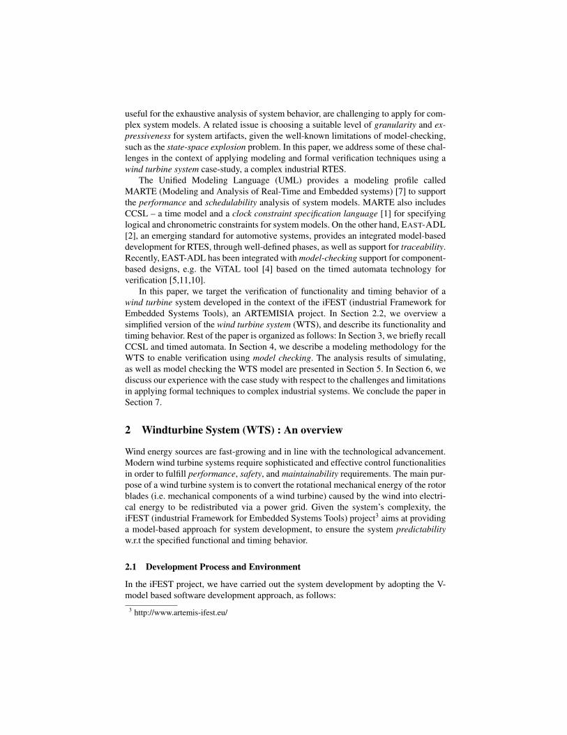
The wind turbine system is modeled as a closed-loop control system, as shown in Fig-ure 1. The key components are the Plant and the Controller subsystems. The Controllerdynamically regulates the rotor blades of the wind turbine w.r.t the specified wind pro-file, to maximize the generation of electrical energy and also to avoid damage to theplant in case of turbulent wind scenarios. It automatically changes the Controller Out-put signal to regulate the plant, based on the wind and the plant’s actual conditions,which are received by the Controller via the Sensor Input signals. The Wind Profileand the Resistive Load are used to simulate and test the behavior of the plant and thecontroller, under specific wind and resistive load conditions. Further details of the plantand controller subsystems are described below.
2.2.1 Plant model. As shown in Figure 2 (in Section 4), it consists of three maincomponents; Servo, Rotor, and Generator. The pitch of the turbine, determined by theController (described below), is actuated by the Servo. The Rotor produces the requiredtorque to maximize the angular speed of the Generator (which produces the final volt-age), based on the pitch value as well as the current wind speed (we assume a fixedresistive load). The Rotor optimizes the produced torque value based on the currentangular speed of the Generator.
2.2.2 Controller model. As shown in Figure 3 (in Section 4), it consists of fourmain components: the Filter, the Main Controller, the Pitch Controller, and the Park
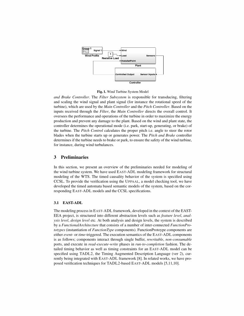
Fig. 1. Wind Turbine System Model
and Brake Controller. The Filter Subsystem is responsible for transducing, filteringand scaling the wind signal and plant signal (for instance the rotational speed of theturbine), which are used by the Main Controller and the Pitch Controller. Based on theinputs received through the Filter, the Main Controller directs the overall control. Itoversees the performance and operations of the turbine in order to maximize the energyproduction and prevent any damage to the plant. Based on the wind and plant state, thecontroller determines the operational mode (i.e. park, start-up, generating, or brake) ofthe turbine. The Pitch Control calculates the proper pitch i.e. angle to steer the rotorblades when the turbine starts up or generates power. The Pitch and Brake controllerdetermines if the turbine needs to brake or park, to ensure the safety of the wind turbine,for instance, during wind turbulances.
3 Preliminaries
In this section, we present an overview of the preliminaries needed for modeling ofthe wind turbine system. We have used EAST-ADL modeling framework for structuralmodeling of the WTS. The timed causality behavior of the system is specified usingCCSL. To provide the verification using the UPPAAL, a model checking tool, we havedeveloped the timed automata based semantic models of the system, based on the cor-responding EAST-ADL models and the CCSL specifications.
3.1 EAST-ADL
The modeling process in EAST-ADL framework, developed in the context of the EAST-EEA project, is structured into different abstraction levels such as feature level, anal-ysis level, design level etc. At both analysis and design levels, the system is describedby a FunctionalArchitecture that consists of a number of inter-connected FunctionPro-totypes (instantiation of FunctionType components). FunctionProtoype components areeither event- or time-triggered. The execution semantics of the EAST-ADL componentsis as follows; components interact through single buffer, rewritable, non-consumableports, and execute in read-execute-write phases in run-to-completion fashion. The de-tailed timing behavior as well as timing constraints for an EAST-ADL model can bespecified using TADL2, the Timing Augmented Description Language (ver 2), cur-rently being integrated with EAST-ADL framework [8]. In related works, we have pro-posed verification techniques for TADL2-based EAST-ADL models [5,11,10].

3.2 CCSL
CCSL is used to specify the constraints imposed on the logical clocks (activation con-ditions) of a model. A CCSL clock is defined as a sequence of instants (event occur-rences). CCSL constraints are of three kinds: (i) Synchronous constraints rely on thenotion of coincidence. For example, the constraint “a coincidesWith b”, denotedby a = b, specifies that each instant of a coincides with the corresponding instant ofb. Another example of a synchronous constraint is “a isPeriodicOn b periodn” , which specifies the subclock a whose ‘ticks’ correspond to every nth ‘tick’ ofb. (ii) Asynchronous constraints are based on instant precedence; the constraint “aisFasterThan b” (denoted by a 4 b) specifies that clock a is (non-strictly)faster than clock b. (iii) Mixed constraints combine coincidence and precedence; theconstraint “c = a delayedFor n on b” specifies that c ‘ticks’ synchronously withthe nth ‘tick’ of b following a ‘tick’.
3.3 Timed Automata
A timed automaton is a tuple < L, l0, C,A,E, I >, where L is a set of locations,l0 ∈ L is the initial location, C is the set of clocks, A is the set of actions, synchroniza-tion actions and the internal τ -action, E ⊆ L× A× B(C)× 2C × L is a set of edgesbetween locations with an action, a guard, a set of clocks to be reset, and I : L→ B(C)assigns clock invariants to locations. A location can be marked urgent (u) or commit-ted (c) to indicate that the time is not allowed to progress in the specified location(s), thelatter being a stricter form indicating further that the next transition can only be takenfrom the corresponding location(s) only. Also, synchronization between two automatais modeled via channels (e.g., x! and x?) with rendezvous or broadcast semantics.
The UPPAAL model-checker extends the timed automata language with a numberof features such as global and local (bounded) integer variables, arithmetic operations,arrays, and a C-like programming language. The tool consists of three parts: a graphicaleditor for modeling timed automata, a simulator for trace generation, and a verifier forthe verification of a system modeled as a network of timed automata. A subset of CTL(computation tree logic) is used as the input language for the verifier. For further details,we refer to UPPAAL tutorial [6].
4 WTS: Formal Specification and Modeling
In this section, we present a formal specification and modeling approach for WTS,an aposteriori modeling technique, that is, the specification and modeling artifacts arebased on existing design artifacts such as Simulink models, requirements documentsetc. However, we apply an abstraction strategy to obtain the corresponding real-timesemantic models that represent the system functionality as well as the timing behav-ior. Further, the strategy attempts to preserve the models’ tractability to make the ex-haustive verification feasible. The overall modeling strategy, based on design principlessuch as separation-of-concerns and correctness-by-construction, captures the underly-ing model-of-computation and the execution behavior of the WTS. Below, we outlinesome generic views/assumptions on which we base our formal modeling:

– Plant models and Instantaneous executions. A Plant model represents phys-ical devices such as sensors and actuators with the corresponding model-of-computation based on reactivity and instantaneity.
– Controller models and Timed executions. Controllers contain software compo-nents based on timed model-of-computation, with explicit timing aspects, such asdelay, execution time, end-to-end deadline etc, to be formally specified and mod-eled.
– Time and event triggering. The activation or triggering of RTES components isgenerally based on specific time or event4 occurrences. Plant components are event-triggered (i.e. in response to occurrence of input data), whereas controller compo-nents are time- or event-triggered, this primarily being a design-choice.
– Run-to-completion. RTES components execute in run-to-completion steps, that is,in terms of read-execute-write cycles.
– Data and value semantics. Due to the associated models-of-computation, as de-scribed above, a data entity at a given ‘instant’, in the Plant or Controller, maycorrespond to two distinct value instants.
– Real-time features. The structural and behavioral models of RTES often fail tomodel real-time features, such as urgency, priority, and synchrony (explained later)w.r.t to the underlying execution model.
– Environment modeling. An environment is external to the system, representingphysical parameters such as temperature, pressure, wind speed etc. To support for-mal verification, a modeling strategy based on non-determinism as well as the prop-erties to be verified, is needed.
To obtain an expressive and verifiable semantic model of the WTS, we employ acomponent-based modeling approach, based on real-time formalisms such as CCSLand timed automata.The overall modeling approach is as follows:
– Data and event representations are made based on the structural models.– The timed causality behavior of the system components, w.r.t the associated model-
of-computation, is formally specified using CCSL constraints.– The functional behavior of the components is modeled using an abstract finite-state-
machine notation, and transformed into timed automata.– The CCSL constraints are transformed into timed automata, and composed using
the notion of synchronization product (described later).
Finally, a real-time semantic model of the overall system is obtained as a network (i.e.,a parallel composition) of timed automata described above.
Fig. 2. Structural modeling: a plant model for the WTS.
4 While time is also an ‘event’, we differentiate this in this paper explicitly.

In Figure 2, we present the structural model of plant and controller for the WTS(based on the corresponding Simulink models), using the EAST-ADL modelingframework (in MetaEdit+5). The main components of the plant, that is SERVO,ROTOR, and GENERATOR are modeled as FunctionalDevice prototypes inEAST-ADL. In Figure 3, we present the structural model of the Controller. It modelsthe three sub-controllers MainControl, PitchRegulation, and ParkBrake, modeledas AnalysisFunctionTypes. For further details of the functionality of thesecomponents, we refer to Section 2.2. We demonstrate the overall modeling approachfor WTS, using the ROTOR and the MainControl components, below. We will alsodiscuss some related modeling issues.
Fig. 3. Structural modeling: a controller model of the WTS.
4.1 Data and Events
As shown in Figure 2, the ROTOR prototype, denoted by RT, receives input pitch(theta), turbine speed (omega), and wind speed (ws) and produces the correspond-ing torque value as the output. Hence, we define the local variables thetal, omegal,and wsl and the corresponding global variables wsg , omegag , thetag . The local vari-ables are updated at the activation of the RT using the corresponding global values. Thisis consistent with the data semantics discussed previously.
1 CCSLclock RT in ; / / r e a d ( i n p u t ) i n s t a n t sCCSLclock RT out ; / / w r i t e ( o u t p u t ) i n s t a n t s
3 CCSLclock RT omega ; / / a c t i v a t i o n ( t r i g g e r ) i n s t a n t s
5 C C S L c o n s t r a i n tRT omega = RT in ; / / RT omega coincidesWith RT in
7 RT in = RT out ; / / RT in coincidesWith RT out
Listing 1.1. CCSL specification of ROTOR component.
4.2 Specification of timed causality behavior
The timed causality behavior of real-time components, w.r.t the correspondingmodel-of-computation, can be specified precisely using CCSL logical clocks andCCSL constraints. We use CCSL (logical) clocks to represent events correspondingto ‘read’, ‘execute’, and ‘write’ instants of a component. In Listing 1.1 and Listing1.2, we present the CCSL specification of ROTOR (RT) and MainControl (MC)
5 www.metacase.com
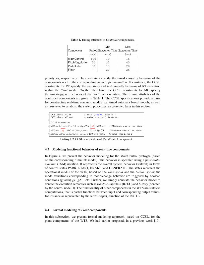
Table 1. Timing attributes of Controller components.
Min MaxComponent Period Execution Time Execution Time
(ms) (ms) (ms)
MainControl 100 10 15PitchRegulation 50 35 45ParkBrake 50 15 20Filter – 20 25
prototypes, respectively. The constraints specify the timed causality behavior of thecomponents w.r.t to the corresponding model-of-computation. For instance, the CCSLconstraints for RT specify the reactivity and instantaneity behavior of RT executionwithin the Plant model. On the other hand, the CCSL constraints for MC specifythe time-triggered behavior of the controller execution. The timing attributes of thecontroller components are given in Table 1. The CCSL specifications provide a basisfor constructing real-time semantic models e.g. timed automata based models, as wellas observers to establish the system properties, as presented later in this section.
1 CCSLclock MC in / / r e a d ( i n p u t ) i n s t a n t sCCSLclock MC out / / w r i t e ( o u t p u t ) i n s t a n t s
3
C C S L c o n s t r a i n t
5 MC in delayedFor 10 on SysClk 4 MC out / / Minimum e x e c u t i o n t ime
MC out 4 MC in delayedFor 15 on SysClk / / Maximum e x e c u t i o n t ime7 MC in isPeriodicWith period 100 on SysClk / / Time t r i g g e r i n g
Listing 1.2. CCSL specification of MainControl component.
4.3 Modeling functional behavior of real-time components
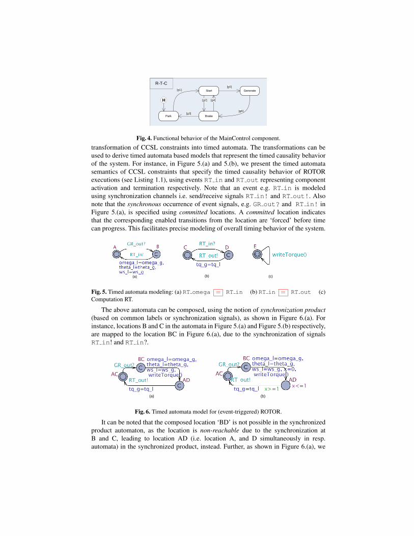
In Figure 4, we present the behavior modeling for the MainControl protoype (basedon the corresponding Simulink model). The behavior is specified using a finite-state-machine (FSM) notation. It represents the overall system behavior (stateful) in termsof control states PARK, START, BRAKE, and GENERATE. The states represent theoperational modes of the WTS, based on the wind speed and the turbine speed; themode transitions corresponding to mode-change behavior are triggered by booleanconditions (guards) g1, g2, .. etc. Further, we simply annotate the behavior model todenote the execution semantics such as run-to-completion (R-T-C) and history (denotedby the control node H). The functionality of other components in the WTS are statelesscomputations, that is partial functions between input and corresponding output values,for instance as represented by the writeTorque() function of the ROTOR.
4.4 Formal modeling of Plant components
In this subsection, we present formal modeling approach, based on CCSL, for theplant components of the WTS. We had earlier proposed, in a previous work [10],
Park
Start
Brake
Generate[g1] [g5]
[g3]
[g2] [g4]
[g6]
H
R-T-C
Fig. 4. Functional behavior of the MainControl component.
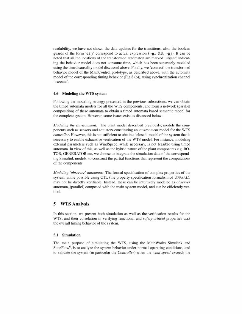
transformation of CCSL constraints into timed automata. The transformations can beused to derive timed automata based models that represent the timed causality behaviorof the system. For instance, in Figure 5.(a) and 5.(b), we present the timed automatasemantics of CCSL constraints that specify the timed causality behavior of ROTORexecutions (see Listing 1.1), using events RT in and RT out representing componentactivation and termination respectively. Note that an event e.g. RT in is modeledusing synchronization channels i.e. send/receive signals RT in! and RT out!. Alsonote that the synchronous occurrence of event signals, e.g. GR out? and RT in! inFigure 5.(a), is specified using committed locations. A committed location indicatesthat the corresponding enabled transitions from the location are ‘forced’ before timecan progress. This facilitates precise modeling of overall timing behavior of the system.
(b) (c)(a)
Fig. 5. Timed automata modeling: (a) RT omega = RT in (b) RT in = RT out (c)Computation RT.
The above automata can be composed, using the notion of synchronization product(based on common labels or synchronization signals), as shown in Figure 6.(a). Forinstance, locations B and C in the automata in Figure 5.(a) and Figure 5.(b) respectively,are mapped to the location BC in Figure 6.(a), due to the synchronization of signalsRT in! and RT in?.
(a) (b)
Fig. 6. Timed automata model for (event-triggered) ROTOR.
It can be noted that the composed location ‘BD’ is not possible in the synchronizedproduct automaton, as the location is non-reachable due to the synchronization atB and C, leading to location AD (i.e. location A, and D simultaneously in resp.automata) in the synchronized product, instead. Further, as shown in Figure 6.(a), we

associate the transitions corresponding to component activation, with data updates andthe corresponding computation; the RT in event denotes input as well as executionof the corresponding functionality, during a transition from location BC to locationAD. However, to make the overall automata model of the WTS system tractable(time-wise), and hence formally verifiable, we need to relax the notion of instantaneityfor the automata models of the Plant components. This can be done by introducinga minimum time delay for each component, if not specified already. This is done byassigning a timing invariant, the delay of one time unit, for instance at location AD inFig.6.(b).
(a) (b) (c)
Fig. 7. Semantic modeling: (a) Periodic triggering (b) Min. exec. time (c) Max. exec. time
4.5 Formal modeling of Controller components
In this subsection, we describe the timed automata modeling of the Controllercomponents for the WTS. In Figure. 7, we present the timed automata semantics ofthe CCSL constraints (Listing 1.2) that specify the time-triggered execution behaviorof the MainControl (MC) prototype. We have composed these automata, as shownin Figure 8.(a), based on the notion of synchronization product (as described in theprevious subsection). This consists of following steps; we have composed the automatain Figure 7.(b) and 7.(c), and then finally with the automaton in Figure 7.(a) (note theinvariant y ≤ 100 at every location in the product automaton).
(a) (b)
Fig. 8. Timed automata modeling of MainControl: (a) time-triggering (b) functional behavior.
As shown in Fig.8.(b), we have also transformed the behavior (functional) modelof the MainControl (Fig.4) component into corresponding timed automaton, followingthe mapping techniques proposed previously [9]. We briefly outline the transformationas follows; we have mapped the control states to automaton locations. Further, usingadditional locations Init and Final and the history variable ‘h’, we have modeled theexecution semantics, that is, run-to-completion, and preserving the history. For model
readability, we have not shown the data updates for the transitions; also, the booleanguards of the form ‘eij’ correspond to actual expression (¬gi && ¬gj). It can benoted that all the locations of the transformed automaton are marked ’urgent’ indicat-ing the behavior model does not consume time, which has been separately modeledusing the timed causality model discussed above. Finally, we ‘connect’ the transformedbehavior model of the MainControl prototype, as described above, with the automatamodel of the corresponding timing behavior (Fig.8.(b)), using synchronization channel‘execute’.
4.6 Modeling the WTS system
Following the modeling strategy presented in the previous subsections, we can obtainthe timed automata models for all the WTS components, and form a network (parallelcomposition) of these automata to obtain a timed automata based semantic model forthe complete system. However, some issues exist as discussed below:
Modeling the Environment: The plant model described previously, models the com-ponents such as sensors and actuators constituting an environment model for the WTScontroller. However, this is not sufficient to obtain a ‘closed’ model of the system that isnecessary to enable exhaustive verification of the WTS model. For instance, modelingexternal parameters such as WindSpeed, while necessary, is not feasible using timedautomata. In view of this, as well as the hybrid nature of the plant components e.g. RO-TOR, GENERATOR etc, we choose to integrate the simulation data of the correspond-ing Simulink models, to construct the partial functions that represent the computationsof the components.
Modeling ‘observer’ automata: The formal specification of complex properties of thesystem, while possible using CTL (the property specification formalism of UPPAAL),may not be directly verifiable. Instead, these can be intuitively modeled as observerautomata, (parallel) composed with the main system model, and can be efficiently ver-ified.
5 WTS Analysis
In this section, we present both simulation as well as the verification results for theWTS, and their correlation in verifying functional and safety-critical properties w.r.tthe overall timing behavior of the system.
5.1 Simulation
The main purpose of simulating the WTS, using the MathWorks Simulink andStateFlow6, is to analyze the system behavior under normal operating conditions, andto validate the system (in particular the Controller) when the wind speed exceeds the
0 10 20 30 40 50 60 70 800
2040
Wind Speed
m/s
ec
0 10 20 30 40 50 60 70 80-202
Rotor Torque
Nm
0 10 20 30 40 50 60 70 800
2040
Rotor Speed
rad
/sec
0 10 20 30 40 50 60 70 80-100
0100
Servo Motor AngleD
eg
0 10 20 30 40 50 60 70 80-100
0100
Pitch
Deg
0 10 20 30 40 50 60 70 80024
Turbine State
Time (sec)
Sta
te
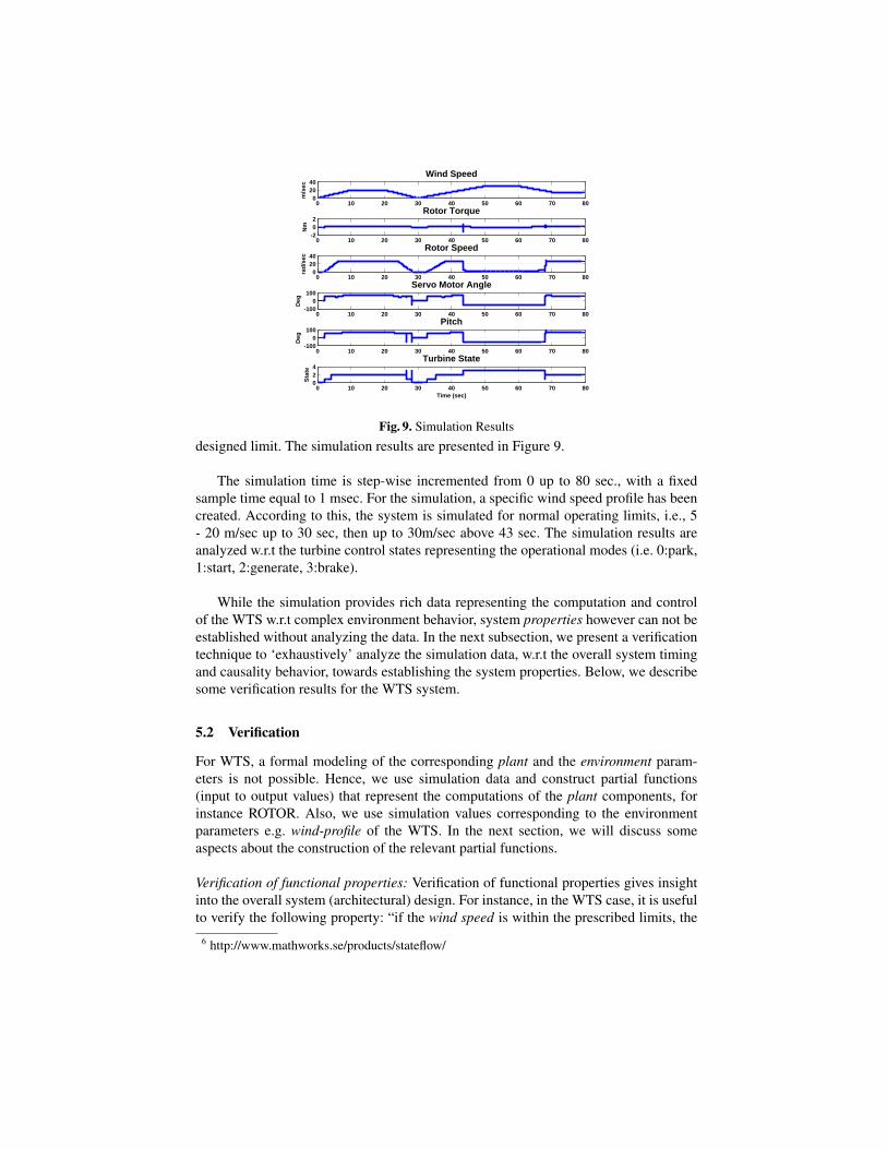
Fig. 9. Simulation Results
designed limit. The simulation results are presented in Figure 9.
The simulation time is step-wise incremented from 0 up to 80 sec., with a fixedsample time equal to 1 msec. For the simulation, a specific wind speed profile has beencreated. According to this, the system is simulated for normal operating limits, i.e., 5- 20 m/sec up to 30 sec, then up to 30m/sec above 43 sec. The simulation results areanalyzed w.r.t the turbine control states representing the operational modes (i.e. 0:park,1:start, 2:generate, 3:brake).
While the simulation provides rich data representing the computation and controlof the WTS w.r.t complex environment behavior, system properties however can not beestablished without analyzing the data. In the next subsection, we present a verificationtechnique to ‘exhaustively’ analyze the simulation data, w.r.t the overall system timingand causality behavior, towards establishing the system properties. Below, we describesome verification results for the WTS system.
5.2 Verification
For WTS, a formal modeling of the corresponding plant and the environment param-eters is not possible. Hence, we use simulation data and construct partial functions(input to output values) that represent the computations of the plant components, forinstance ROTOR. Also, we use simulation values corresponding to the environmentparameters e.g. wind-profile of the WTS. In the next section, we will discuss someaspects about the construction of the relevant partial functions.
Verification of functional properties: Verification of functional properties gives insightinto the overall system (architectural) design. For instance, in the WTS case, it is usefulto verify the following property: “if the wind speed is within the prescribed limits, the
6 http://www.mathworks.se/products/stateflow/

controller eventually moves to Generate mode”. The property can be formulated asa liveness property or leads to property (denoted by , implemented as --> inUPPAAL), as below.
(ws>=5 && ws<=20) --> state==2 (1)
Verification of safety-critical properties: One of the safety-critical requirements for theWTS is to fulfill the following property: “the wind turbine moves to Parkmode, within30s from detecting that the wind speed has crossed the upper limit of 20m/sec”. Toverify the property (w.r.t to simulation data), we construct an observer automata for theproperty as shown in Fig.10, compose the observer with the system model, and verifythat the corresponding invariant, the Property (2), holds for the composed model. Notethat the urgent channel ‘U!’ forces the transition from location B to A without anyfurther delay, when the corresponding transition is enabled.
A� obs.B implies x <= 30 (2)
x=0
x=0 BA
U!state==3
ws>20
Fig. 10. An observer automata to verify the safety-property: A[] obs.B implies x<=30
Verifying reachability properties: We can verify reachability of specific control statesor computation. For instance, using the Property 3, a reachability property, we canverify that the control state ‘Park’ (Figure 8.(b)) has been reached (at least once) duringthe simulation of the WTS. While this may be easily validated using the simulationtrace, we can use similar properties to verify specific ‘error’ states e.g. by extendingthe behavior model with special ‘locations’ that are reached if the corresponding ‘error’is detected. The presence of these error locations in the simulation data can then be‘exhaustively’ verified.
∃ <> MC.Park (3)
Verifying deadlock-freeness: Using the Property 4, we can verify that the system isdeadlock-free, w.r.t overall timed causality behavior of the WTS, as modeled by thecorresponding timed automata model. The property is an important validation of thesystem, which can not be achieved using simulation only, as the corresponding Simulinkmodel does not represent the timing behavior of the system explicitly. Also, the prop-erty, when satisfied, verifies the correctness (i.e. consistency) of the timing attributes(Table 1) associated with the system (architectural) design.
A� (not deadlock) (4)

6 Discussion and Lessons-learned
In this paper, we have presented a formal modeling and verification approach for anindustrial system, namely a wind turbine system. The main goal of the work has been toprovide formal verification as a complementary analysis method to existing validationtechniques based primarily on simulation. We have successfully addressed the follow-ing challenges:
– Abstract but expressive system models: Using real-time formalisms such as CCSLand timed automata, we were able to construct intuitive system models amenablefor exhaustive verification (w.r.t to timing). With the separation of timing andfunctional modeling, the technique is scalable to complex system models.
– Verification as complementary analysis to simulation: The verification is based on‘exhaustively’ analyzing the simulation data w.r.t the timing behavior of the sys-tem. While verification models are expressive in terms of system structure andprecise timing behavior, simulation models are suitable to specify plant and theenvironment, e.g. ‘wind profile’ modeling in the case of WTS simulation. Thus, theverification approach provides an enhanced simulation-based validation.
The formal modeling approach for the wind turbine system considers the cor-responding simulation results to model a suitable abstraction of the plant model. Itfacilitates constructing a formal model of the WTS, including the plant behavior. Thiswas primarily one of the obstacles in earlier efforts to achieve formal verificationof the system. Besides, the formal models were only possible due to expressivenessof real-time semantic formalisms such as CCSL and modeling flexibility in timedautomata, as demonstrated in this paper. Further, we believe that the modeling approachis scalable to large complex systems, due to parallel composition of semantic models(timed automata) representing system components. For the verification results, we haveconsidered only the control properties of the system with respect to the overall timedcausality behavior. However, we can also consider the data values in the verification,due to timed automata variables. Thus, we have combined the expressiveness of CCSLwith modeling capabilities of timed automata.
However, some limitations of our approach do exist. The exhaustiveness of the veri-fication is limited to partial functions constructed using specific instance(s) of simula-tion. Hence, the approach may be similar to testing-based analysis (albeit model-based).Hence, we need strategies, e.g. choosing suitable simulation step and data profiles, togenerate simulation data w.r.t the system properties to be verified. Further, it may benoted that the simulation-extended verification approach presented above may be suit-able for data-intensive control systems (e.g. hybrid systems), such as the wind turbinesystem case study presented in the paper. On the other hand, control-intensive systemsmay be exhaustively modeled and verifiable using model-checking independent of sim-ulation.
7 Conclusion
In this paper, we have presented a formal modeling and verification approach for anindustrial case-study, namely an example wind turbine system. The architectural andbehavioral modeling, partially based on the existing system artifacts such as Simulink-models, additionally captures precise timing behavior of the system. The modeling ap-proach, based on the real-time formalisms such as CCSL and timed automata, alsointegrates simulation data to model plant and environment behavior. Based on this, theproposed verification technique using model-checking, enhances the simulation-basedsystem validation. Besides verifying functional properties that validate correctness ofthe system design, safety-critical properties w.r.t the overall system timing behaviorcan also be verified. This is clearly an important analysis step forward within existingvalidation approaches for industrial applications. Thus the paper addresses V&V chal-lenges in the industrial context, by combining both simulation and verification tech-niques, paving the way towards scalable application of model-checking for an enhancedvalidation process. As future work, we intend to investigate requirement-driven strate-gies to derive the simulation criteria for generating relevant partial functions. This leadsto enhanced validation process that can verify useful classes of system properties.
Acknowledgment
This work was partially funded by Swedish Research Council (project ARROWS),Malardalen University (Sweden), and ARTEMISIA project iFEST.
References
1. Andre, C., Mallet, F., de Simone, R.: Modeling Time(s). In: Models’07. LNCS, vol. 4735,pp. 559–573. Springer (2007)
2. ATESST (Advancing Traffic Efficiency through Software Technology): East-ADL2 specifi-cation (March 2008), http://www.atesst.org, 2008-03-20
3. Bouyssounouse, B., Sifakis, J.: Embedded Systems Design: The ARTIST Roadmap for Re-search and Development (Lecture Notes in Computer Science). Springer-Verlag New York,Inc., Secaucus, NJ, USA (2005)
4. Enoiu, E.P., Marinescu, R., Seceleanu, C., Pettersson, P.: Vital : A verification tool for east-adl models using uppaal port. In: ICECCS’12 (July 2012)
5. Goknil, A., Suryadevara, J., Peraldi-Frati, M.A., Mallet, F.: Analysis Support for TADL2Timing Constraints on EAST-ADL Models. In: ECSA 2013 : 7th European Conference onSoftware Architecture. p. 10 pages. LNCS, Montpellier, France (Jul 2013)
6. Larsen, K.G., Pettersson, P., Yi, W.: UPPAAL in a Nutshell. Int. Journal on Software Toolsfor Technology Transfer 1(1–2), 134–152 (Oct 1997)
7. OMG: UML Profile for MARTE, v1.0. Object Management Group (November 2009),formal/2009-11-02
8. Peraldi-Frati, M.A., Goknil, A., DeAntoni, J., Nordlander, J.: A Timing Model for SpecifyingMulti Clock Automotive Systems: The Timing Augmented Description Language V2. In:ICECCS 2012. pp. 230–239 (2012)

9. Slutej, D., Hakansson, J., Suryadevara, J., Seceleanu, C., Pettersson, P.: Analyzing a pattern-based model of a real-time turntable system. In: Jens Happe, B.Z. (ed.) 6th Interna-tional Workshop on Formal Engineering approaches to Software Components and Architec-tures(FESCA), ETAPS’09, York, UK, March. pp. 161–178. Electronic Notes in TheoreticalComputer Science (ENTCS), Vol 253, Elsevier (September 2009)
10. Suryadevara, J., Seceleanu, C., Mallet, F., Pettersson, P.: Verifying MARTE/CCSL modebehaviors using UPPAAL. In: 11th International Conference on Software Engineering andFormal Methods (SEFM 2013) (September 2013)
11. Suryadevara, J.: Validating EAST-ADL timing constraints using UPPAAL. In: 39th Euromi-cro Conference on Software Engineering and Advanced Applications SEAA 2013) (Septem-ber 2013)