WIND TURBINE OPTIMAL POWER CONTROL BASED · PDF filewind speed is required to extract maximum...
11
http://www.iaeme.com/IJMET/index.asp 390 [email protected] International Journal of Mechanical Engineering and Technology (IJMET) Volume 8, Issue 10, October 2017, pp. 390–400, Article ID: IJMET_08_10_043 Available online at http://www.iaeme.com/IJMET/issues.asp?JType=IJMET&VType=8&IType=10 ISSN Print: 0976-6340 and ISSN Online: 0976-6359 © IAEME Publication Scopus Indexed WIND TURBINE OPTIMAL POWER CONTROL BASED ON ADAPTIVE TWISTING ALGORITHM: APPLICATION TO CAPSIM- WIND FARM IN MOROCCO Morad Hafiane, Jalal Sabor and Mohammed Taleb CP2S team / LSMI laboratory -ENSAM- Engineering School, Meknes, Morocco ABSTRACT Accurate control of the wind turbine at its optimal rotational speed for a given wind speed is required to extract maximum power from the wind turbine generator system in the absence of aerodynamic pitch control. Due to inherent wind turbine nonlinearities and unpredictable wind speed fluctuations, precise control is a difficult task to undertake. This paper presents a command strategy for a wind turbine, based on a maximum power point tracking (MPPT) algorithm with a modified Hill Climb Searching (HCS) and a sliding mode controller with adaptive Twisting algorithm in order to maximize the output power, under the wind turbine’s nonlinear dynamics and fast wind changes. The application to CAPSIM wind farm highlight the performance of the proposed strategy under various wind speed operating conditions. Key words: Wind Turbine (WT), Hill Climb Searching (HSC), Doubly Fed Induction Generator (DFIG), High Order Sliding Mode (HOSM), Adaptive Twisting (AT). Cite this Article: Morad Hafiane, Jalal Sabor and Mohammed Taleb, Wind Turbine Optimal Power Control based on Adaptive Twisting Algorithm: Application to Capsim-Wind Farm in Morocco, International Journal of Mechanical Engineering and Technology 8(10), 2017, pp. 390–400. http://www.iaeme.com/IJMET/issues.asp?JType=IJMET&VType=8&IType=10 1. INTRODUCTION In the last decade, alternative energy sources such as renewable energies have received a thorough attention and have been considered as a way of fighting climate change. Among renewable energies, wind turbine has become the world’s fastest growing energy generator. As for Morocco, the wind energy potential is estimated at 2.5 GW [22], this makes the investment in this sector very motivating. Morocco has invested heavily in this sector, which has reached $ 3.5 billion. These investments have resulted in 9 wind farms in the different regions of the country. These farms are equipped with horizontal axis wind turbines (unit power 850 KW).
Transcript of WIND TURBINE OPTIMAL POWER CONTROL BASED · PDF filewind speed is required to extract maximum...
http://www.iaeme.com/IJMET/index.asp 390 [email protected]
International Journal of Mechanical Engineering and Technology (IJMET) Volume 8, Issue 10, October 2017, pp. 390–400, Article ID: IJMET_08_10_043 Available online at http://www.iaeme.com/IJMET/issues.asp?JType=IJMET&VType=8&IType=10 ISSN Print: 0976-6340 and ISSN Online: 0976-6359 © IAEME Publication Scopus Indexed
WIND TURBINE OPTIMAL POWER CONTROL
BASED ON ADAPTIVE TWISTING
ALGORITHM: APPLICATION TO CAPSIM-
WIND FARM IN MOROCCO
Morad Hafiane, Jalal Sabor and Mohammed Taleb
CP2S team / LSMI laboratory -ENSAM- Engineering School, Meknes, Morocco
ABSTRACT
Accurate control of the wind turbine at its optimal rotational speed for a given
wind speed is required to extract maximum power from the wind turbine generator
system in the absence of aerodynamic pitch control. Due to inherent wind turbine
nonlinearities and unpredictable wind speed fluctuations, precise control is a difficult
task to undertake. This paper presents a command strategy for a wind turbine, based
on a maximum power point tracking (MPPT) algorithm with a modified Hill Climb
Searching (HCS) and a sliding mode controller with adaptive Twisting algorithm in
order to maximize the output power, under the wind turbine’s nonlinear dynamics and
fast wind changes. The application to CAPSIM wind farm highlight the performance
of the proposed strategy under various wind speed operating conditions.
Key words: Wind Turbine (WT), Hill Climb Searching (HSC), Doubly Fed Induction Generator (DFIG), High Order Sliding Mode (HOSM), Adaptive Twisting (AT).
Cite this Article: Morad Hafiane, Jalal Sabor and Mohammed Taleb, Wind Turbine Optimal Power Control based on Adaptive Twisting Algorithm: Application to Capsim-Wind Farm in Morocco, International Journal of Mechanical Engineering and Technology 8(10), 2017, pp. 390–400. http://www.iaeme.com/IJMET/issues.asp?JType=IJMET&VType=8&IType=10
1. INTRODUCTION
In the last decade, alternative energy sources such as renewable energies have received a thorough attention and have been considered as a way of fighting climate change. Among renewable energies, wind turbine has become the world’s fastest growing energy generator. As for Morocco, the wind energy potential is estimated at 2.5 GW [22], this makes the investment in this sector very motivating.
Morocco has invested heavily in this sector, which has reached $ 3.5 billion. These investments have resulted in 9 wind farms in the different regions of the country. These farms are equipped with horizontal axis wind turbines (unit power 850 KW).
Wind Turbine Optimal Power Control based on Adaptive Twisting Algorithm: Application to Capsim-Wind Farm in Morocco
http://www.iaeme.com/IJMET/index.asp 391 [email protected]
In these farms, the power control is performed using the pitch control strategy, which causes a variation in the turbine speed and subsequently its power. This technique has the main advantage of reducing considerably the stress on the turbine. However, a blade orientation system is required, which requires energy for its operation, as well as its maintenance is expensive [3]. The pitch control technique doesn’t allow an efficient extraction of the wind power, and especially in the case of wind speed rapid change, which causes a significant loss of the generated power.
In this paper, we introduce another strategy of power control, based on the electromechanical torque control of Doubly Fed Induction Generators (DFIG) [1],[2], in which the maximum power can be obtained, by adjusting the generator speed to follow its optimal value generated by a maximum power point tracking (MPPT) system[4], this latter and according to the wind change, wind turbine specifications, and operating generator speed, generates an optimal setpoint to the inverter in rotor side and then controls the speed generator. This technique has the advantage of being less expensive, effective in wind speed rapid change. But it’s difficult to implement, because of the uncertainties in the parameters of the generator. To perform this task, we have introduced a new robust controller based on high order sliding mode (HOSM), with adaptive Twisting algorithm [18], [19] and [10], considering the significant advantages of this type of controller. The rest of the paper is organized as follows: section 2 outlines the wind turbine dynamic model. The MPPT algorithm is detailed in section 3. In section 4, the HOSM controller design. Simulation results and the application to CAPSIM wind farm are reported and discussed in section 5.
2. WIND TURBINE DYNAMICS
2.1. Wind dynamics
The dynamic equation of the power produced by a wind turbine [4], [5] is:
, 1111
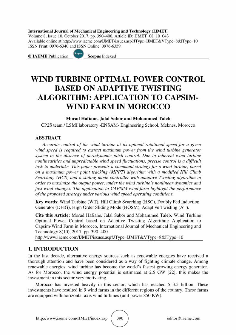
Where ρ is the air density, R is the turbine radius and v is the wind speed. Cp(λ,β) is the power coefficient, it is given by the equation [6],[7] below:
, 0.44 0.0167 ! ".#$ 0.00184 3 2222
Where λ )*.+, and Ω* is the wind turbine speed. β: Turbine blades orientation angle.
Figure 1 Power coefficient curve Cp(λ) versus tip speed ratio (TSR) λ , with β=0°

Morad Hafiane, Jalal Sabor and Mohammed Taleb
http://www.iaeme.com/IJMET/index.asp 392 [email protected]
2.2. Mechanical dynamics
The mechanical system equation can be expressed by:
. /0/1 1 23 4 (3)(3)(3)(3)
Where, J: the generator and turbine Inertia. Ct: mechanical torque.
Cem: electromechanical torque. Cf: friction torque. Ω: angular generator speed.
2.3. Electrical dynamics
The DFIG dynamic mathematical model in the d-q axes rotating reference frame can be described by the following equations [8]: /5 = . /5 + /789/1 − :;<5 (4a)(4a)(4a)(4a)
<5 = . <5 + /7>9/1 + :;/5 (4b)(4b)(4b)(4b) /@ = A. /@ + /78B/1 − :A;<@ (4c)(4c)(4c)(4c) <@ = A. <@ + /7>B/1 + :A;/@ (4d)(4d)(4d)(4d) With ;/5 = E. /5 + E3. /@ (5a)(5a)(5a)(5a) ;<5 = E. <5 + E3. <@ (5b)(5b)(5b)(5b) ;/@ = EA. /@ + E3. /5 (5c)(5c)(5c)(5c) ;<@ = EA. <@ + E3. <5 (5d)(5d)(5d)(5d) Where,
vds, vqs : Stator voltage φds, φqs : Stator flux linkage
vdr, vqr : Rotor voltage φdr, φqr : Rotor flux linkage
ids, iqs : Stator current Rs, Rr : Stator and rotor resistance
idr, iqr : Rotor current Ls Lr : Stator and Rotor cyclic inductance
ωs, ωr : Stator and rotor speed Lm : Magnetizing (mutual) inductance
The stator speed and the electromechanical torque are described as: : = :A + G ((((6a)6a)6a)6a) HI = (;J. K + ;K. J) (6b)(6b)(6b)(6b) Where, P is the number of poles. The active and the reactive power are expressed as: = JJ + KK (7a)(7a)(7a)(7a) A = JAJA + KAKA (7(7(7(7b)b)b)b) L = −JK + KJ (7c)(7c)(7c)(7c) LA = JAKA + KAJA (7d)(7d)(7d)(7d) The DFIGs are widely used in many industrial applications such as wind turbines and
electric vehicles thanks to their high-performance and low cost [9]. However, these systems are driven by complex dynamics. To reduce this complexity, the generator’s flux and torque are controlled separately. For that, a decoupling is achieved using a coordinate transformation, which is called field-oriented control (FOC) technique. Therefore, the DFIG flux can be expressed as, ;J = ; (8a)(8a)(8a)(8a) ;K = 0 (8b)(8b)(8b)(8b)
Which yields from (5a) and (5b)?
Wind Turbine Optimal Power Control based on Adaptive Twisting Algorithm: Application to Capsim-Wind Farm in Morocco
http://www.iaeme.com/IJMET/index.asp 393 [email protected]
J = ;E − EIE JA (9a)(9a)(9a)(9a) K = EIE KA (9b)(9b)(9b)(9b) Therefore, the electromechanical torque (6b) is written as, HI = − EIE ;KA (10)(10)(10)(10) Stator resistance is usually neglected for large machines and flux ϕO is taken to be
constant. Therefore, the formulation (4a) and (4b) can be written as, J = 0 (11a)(11a)(11a)(11a) K = = :; (11b)(11b)(11b)(11b) Substituting (9a) and (9b) in (5c) and (5d) yields, ;JA = EIE ; + PEA. JA (12a)(12a)(12a)(12a) ;KA = PEA. KA (12b)(12b)(12b)(12b) Where, P = 1 − QRSQ9QB Substituting Фdr and Фqr from (12) into (4c) and (4d) leads to, JA = A. JA + PEA JJAJT − :APEA. KA (13a)(13a)(13a)(13a) KA = A. KA + PEA JKAJT + :A. PEA. JA + U:A (13b)(13b)(13b)(13b) Where, V = WXWY ZY
The stator active and the reactive power in (7) are expressed as: = − EIE KA (14a)(14a)(14a)(14a) L = ;E − EIE JA (14b)(14b)(14b)(14b)
3. MPPT ALGORITHMS
In the HCS algorithm, the wind turbine output power is directly controlled and optimized. It allows to reach the maximum power point (MPP) at a given wind speed [10],[11], by locating the side of the MPP in the theoretical power curve, and force the generator, through a rotor side inverter, to reach it. To achieve this goal, the inverter in rotor side, disturbs the control variable, with some step value and measures the output power until the MPP [10], [11] is reached. However, and during rapid wind changes, the algorithm fails to locate the right side of the MPP.
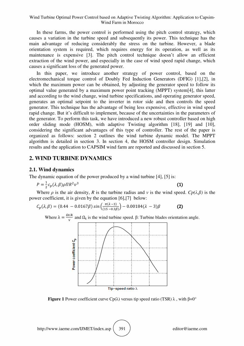
To overcome this failure, the modified HCS algorithm has been proposed in [10],[12]. The variable step size and the direction of the next perturbation are calculated by observing the distance between the generator speed at the operating point and its corresponding in the optimal power curve [10], [12], [13],[14] at the operating power Figure 2.
Morad Hafiane, Jalal Sabor and Mohammed Taleb
http://www.iaeme.com/IJMET/index.asp 394 [email protected]
Figure 2 Modified HCS flowchart
The accuracy and the efficiency of the proposed algorithm [12] depend on the performance of the controller used, thus the significant inertia of wind turbine also influences the effectiveness of this algorithm.
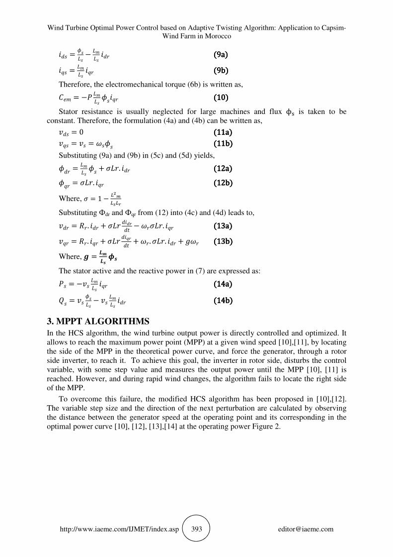
Indeed, this algorithm introduces an improvement of classical, which requires a very fast system feedback under fast wind changes, and the speed setpoint should be achieved very fast and accurately. To this end, a robust controller based on sliding mode has been applied to control DFIG under various wind change, as it shown in figure 3.
Figure 3 HCS MPPT algorithm with HOSM controller

Wind Turbine Optimal Power Control based on Adaptive Twisting Algorithm: Application to Capsim-Wind Farm in Morocco
http://www.iaeme.com/IJMET/index.asp 395 [email protected]
4. SLIDING MODE CONTROLLER
To design a sliding mode controller, there are three steps [15]:
1. Choosing a sliding surface,
2. Define the convergence conditions.
3. Design a stabilizing control law.
4.1. Sliding surface
The sliding surface S defines the desired dynamic behavior of the system and the error convergence. The sliding surface is given by the following equation [15]: [(\) = ( ]]1 + ) ^ H(\) (15)(15)(15)(15)
Where, λ is a strictly positive constant and n is the smallest positive integer to ensure
controllability such that _O_* ≠ 0 and e(x) is the error.
4.2. Convergence condition
Two conditions must be satisfied for the system to converge to the sliding surface: the reaching condition and the sliding condition. Consider a positive scalar function V (x) > 0. The control law has to force the decrease of this function to make the sliding surface attractive and invariant [15]. Choosing b(\) = [(\) (16)(16)(16)(16)
Taking the time derivative of V(x) results into the following condition,V(x) < 0, i.e., S(x). S(x) < 0.
4.3. Stabilizing control law
This condition is used to determine appropriate control laws that bring controlled variables to their respective sliding surface and keep them on it until the equilibrium point is reached. The DFIG dynamic equations (3) and (13) can be written as, . /0/1 = 1 − QSQ9 ;5<@ − G. g (17a)(17a)(17a)(17a)
JKAJT = 1P (KA − A. KA − :A. P. JA − U:A) (17b)(17b)(17b)(17b) JJAJT = 1P (JA − A. JA + :AP. KA) (17c)(17c)(17c)(17c) Therefore, define the speed tracking sliding variable as, [ = G − G∗ (18)(18)(18)(18) Where, Ω* is the reference speed. Taking the derivative of S and substituting
_)_* from
(17a) yields, J[(G)JT = 1. T + EIE ;KA − G. g$ − JG∗JT (19a)(19a)(19a)(19a)
J[(G)JT = 1. T` + EIE ; JKAJT − G. g$ − JG∗JT (19b)(19b)(19b)(19b)
Substituting ıjk` from (17b) into (19b) leads to,
J[(G)JT = 1. lT` − EIE ;(1P (KA − A. KA − :A. P. JA − U:A)) − G. gm − JG∗JT (20)(20)(20)(20)
Where, vrq is the control variable law of the wind turbine.
Morad Hafiane, Jalal Sabor and Mohammed Taleb
http://www.iaeme.com/IJMET/index.asp 396 [email protected]
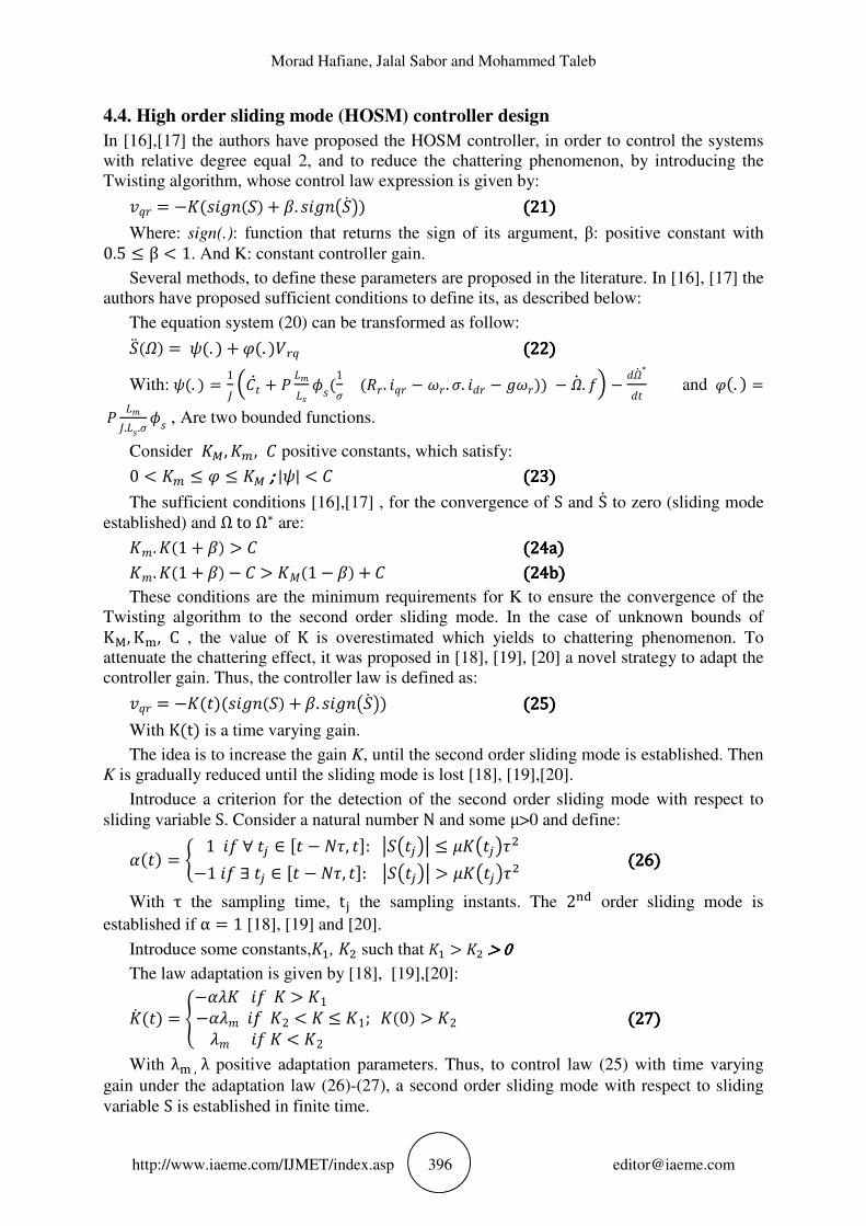
4.4. High order sliding mode (HOSM) controller design
In [16],[17] the authors have proposed the HOSM controller, in order to control the systems with relative degree equal 2, and to reduce the chattering phenomenon, by introducing the Twisting algorithm, whose control law expression is given by: KA = −n(U([) + . Uo[p) (21)(21)(21)(21)
Where: sign(.): function that returns the sign of its argument, β: positive constant with 0.5 ≤ β < 1. And K: constant controller gain.
Several methods, to define these parameters are proposed in the literature. In [16], [17] the authors have proposed sufficient conditions to define its, as described below:
The equation system (20) can be transformed as follow: [s (G) = t(. ) + u(. )bAK (22)(22)(22)(22) With: t(. ) = 1. T + EIE ;(1P (A. KA − :A. P. JA − U:A)) − G. g$ − JG∗
JT and u(. ) = EI..E.P ; , Are two bounded functions.
Consider nv, n3, positive constants, which satisfy: 0 < n3 ≤ u ≤ nv ; ; ; ; |t| < (23)(23)(23)(23) The sufficient conditions [16],[17] , for the convergence of S and S to zero (sliding mode
established) and Ω to Ω∗ are: nI. n(1 + ) > (24a)(24a)(24a)(24a) nI. n(1 + ) − > n|(1 − ) + (24b)(24b)(24b)(24b) These conditions are the minimum requirements for K to ensure the convergence of the
Twisting algorithm to the second order sliding mode. In the case of unknown bounds of K~, K, C , the value of K is overestimated which yields to chattering phenomenon. To attenuate the chattering effect, it was proposed in [18], [19], [20] a novel strategy to adapt the controller gain. Thus, the controller law is defined as: KA = −n(T)(U([) + . Uo[p) (25)(25)(25)(25)
With K(t) is a time varying gain.
The idea is to increase the gain K, until the second order sliding mode is established. Then K is gradually reduced until the sliding mode is lost [18], [19],[20].
Introduce a criterion for the detection of the second order sliding mode with respect to sliding variable S. Consider a natural number N and some μ>0 and define:
(T) = 1 g ∀ T ∈ T − , T: [oTp ≤ noTp −1 g ∃ T ∈ T − , T: [oTp > noTp (26)(26)(26)(26) With τ the sampling time, t the sampling instants. The 2_ order sliding mode is
established if α = 1 [18], [19] and [20].
Introduce some constants,n, n such that n > n > 0> 0> 0> 0
The law adaptation is given by [18], [19],[20]:
n(T) = −n g n > n1 −I g n2 < n ≤ n1; n(0) > n2 I g n < n2 (27)(27)(27)(27) With λ , λ positive adaptation parameters. Thus, to control law (25) with time varying
gain under the adaptation law (26)-(27), a second order sliding mode with respect to sliding variable S is established in finite time.
Wind Turbine Optimal Power Control based on Adaptive Twisting Algorithm: Application to Capsim-Wind Farm in Morocco
http://www.iaeme.com/IJMET/index.asp 397 [email protected]
The algorithm stability and the convergence proof are detailed in [19],[20].
5. SIMULATION RESULTS AND DISCUSSION
5.1. Setup
To demonstrate the performance of the proposed approach, a computer simulation is carried out on the wind turbine model described in section 2. Table 1 summarizes the system’s parameters along with their respective values.
HOSM controller coefficients are set to β=0.9, K=100, K=1, λm=500, λ=500. The sampling frequency is set to 10 KHz.
HCS algorithm parameters are set to: µ=0.01, ΔΩ=0,1 rad/s.
Table 1 Wind turbine GAMESA/G52 850 KW parameters [21]
Parameter Value
Turbine’s diameter (m) d=52
Total inertia (kg·m2) J=400
Air density (kg·m3) ρ=1,225
Gear reduction ratio r=61,74
Generator’s frequency (Hz) f=50
Generator’s q-axis stator voltage (V) V=690
Generator’s stator resistance(Ω) Rs=0,00297
Generator’s rotor resistance(Ω) Rr=0,00382
Generator’s stator inductance (H) Ls=0,121
Generator’s rotor inductance (H) Lr=0,0573
Generator’s cyclic inductance (H Lm=0,031
5.2. CAPSIM wind Farm
5.2.1. The current situation
This site is located in Essaouira city (South of Morocco), which contains about 71 wind turbines, with a total installed capacity of 60.35 MW, and an annual output of 210 GWh[22]. For simplicity, we have limited the study to a single wind turbine (850 KW).
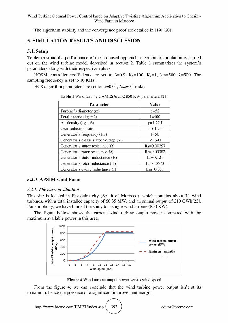
The figure bellow shows the current wind turbine output power compared with the maximum available power in this area.
Figure 4 Wind turbine output power versus wind speed
From the figure 4, we can conclude that the wind turbine power output isn’t at its maximum, hence the presence of a significant improvement margin.
Morad Hafiane, Jalal Sabor and Mohammed Taleb
http://www.iaeme.com/IJMET/index.asp 398 [email protected]
5.2.2. The projected situation
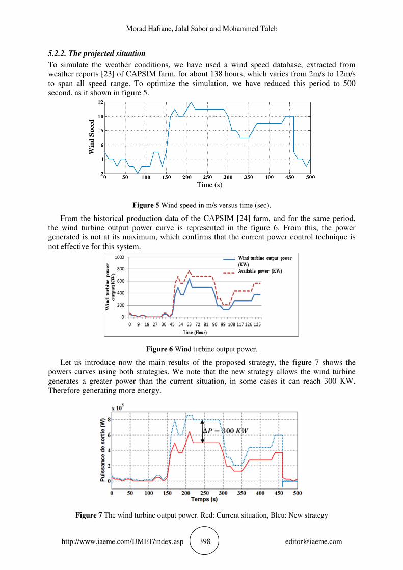
To simulate the weather conditions, we have used a wind speed database, extracted from weather reports [23] of CAPSIM farm, for about 138 hours, which varies from 2m/s to 12m/s to span all speed range. To optimize the simulation, we have reduced this period to 500 second, as it shown in figure 5.
Figure 5 Wind speed in m/s versus time (sec).
From the historical production data of the CAPSIM [24] farm, and for the same period, the wind turbine output power curve is represented in the figure 6. From this, the power generated is not at its maximum, which confirms that the current power control technique is not effective for this system.
Figure 6 Wind turbine output power.
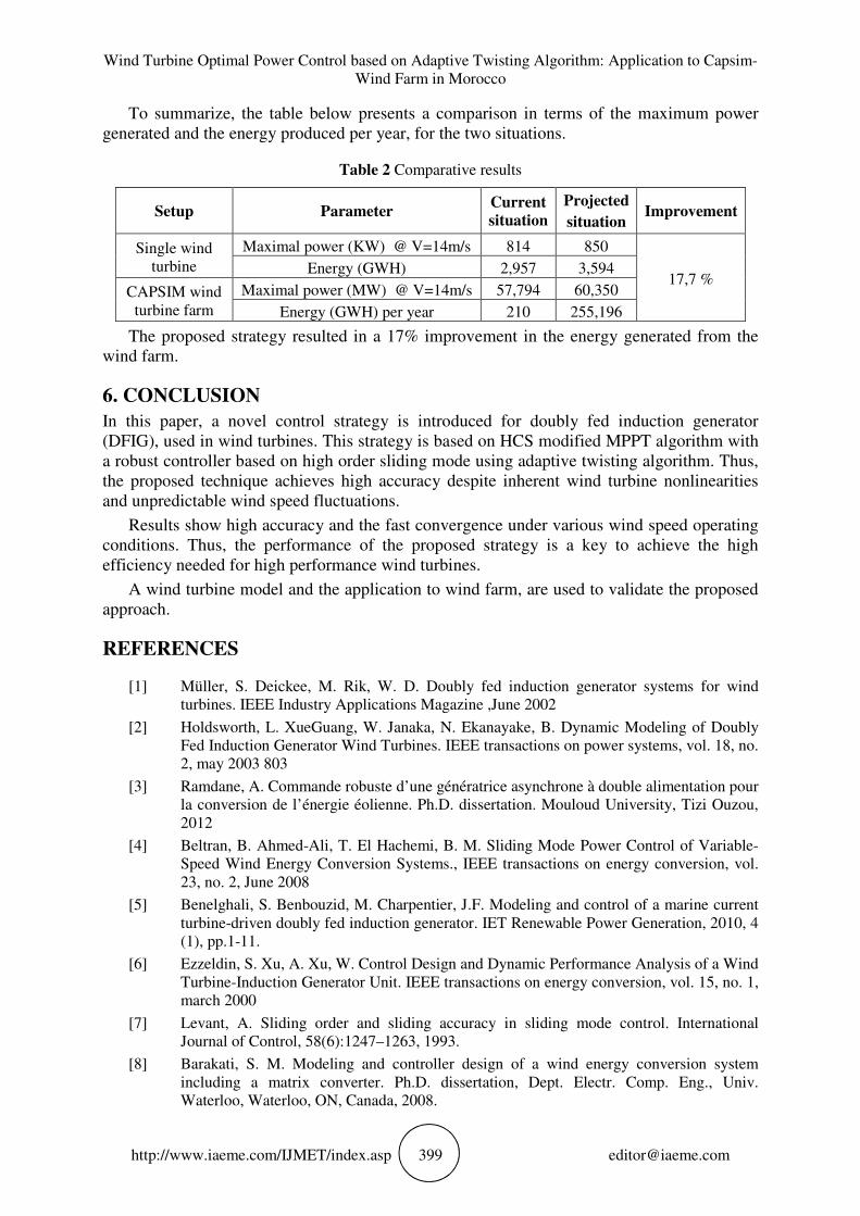
Let us introduce now the main results of the proposed strategy, the figure 7 shows the powers curves using both strategies. We note that the new strategy allows the wind turbine generates a greater power than the current situation, in some cases it can reach 300 KW. Therefore generating more energy.
Figure 7 The wind turbine output power. Red: Current situation, Bleu: New strategy
Time (s)
Win
d S
pee
d
Wind Turbine Optimal Power Control based on Adaptive Twisting Algorithm: Application to Capsim-Wind Farm in Morocco
http://www.iaeme.com/IJMET/index.asp 399 [email protected]
To summarize, the table below presents a comparison in terms of the maximum power generated and the energy produced per year, for the two situations.
Table 2 Comparative results
Setup Parameter Current
situation
Projected
situation Improvement
Single wind turbine
Maximal power (KW) @ V=14m/s 814 850
17,7 % Energy (GWH) 2,957 3,594
CAPSIM wind turbine farm
Maximal power (MW) @ V=14m/s 57,794 60,350
Energy (GWH) per year 210 255,196
The proposed strategy resulted in a 17% improvement in the energy generated from the wind farm.
6. CONCLUSION
In this paper, a novel control strategy is introduced for doubly fed induction generator (DFIG), used in wind turbines. This strategy is based on HCS modified MPPT algorithm with a robust controller based on high order sliding mode using adaptive twisting algorithm. Thus, the proposed technique achieves high accuracy despite inherent wind turbine nonlinearities and unpredictable wind speed fluctuations.
Results show high accuracy and the fast convergence under various wind speed operating conditions. Thus, the performance of the proposed strategy is a key to achieve the high efficiency needed for high performance wind turbines.
A wind turbine model and the application to wind farm, are used to validate the proposed approach.
REFERENCES
[1] Müller, S. Deickee, M. Rik, W. D. Doubly fed induction generator systems for wind turbines. IEEE Industry Applications Magazine ,June 2002
[2] Holdsworth, L. XueGuang, W. Janaka, N. Ekanayake, B. Dynamic Modeling of Doubly Fed Induction Generator Wind Turbines. IEEE transactions on power systems, vol. 18, no. 2, may 2003 803
[3] Ramdane, A. Commande robuste d’une génératrice asynchrone à double alimentation pour la conversion de l’énergie éolienne. Ph.D. dissertation. Mouloud University, Tizi Ouzou, 2012
[4] Beltran, B. Ahmed-Ali, T. El Hachemi, B. M. Sliding Mode Power Control of Variable-Speed Wind Energy Conversion Systems., IEEE transactions on energy conversion, vol. 23, no. 2, June 2008
[5] Benelghali, S. Benbouzid, M. Charpentier, J.F. Modeling and control of a marine current turbine-driven doubly fed induction generator. IET Renewable Power Generation, 2010, 4 (1), pp.1-11.
[6] Ezzeldin, S. Xu, A. Xu, W. Control Design and Dynamic Performance Analysis of a Wind Turbine-Induction Generator Unit. IEEE transactions on energy conversion, vol. 15, no. 1, march 2000
[7] Levant, A. Sliding order and sliding accuracy in sliding mode control. International Journal of Control, 58(6):1247–1263, 1993.
[8] Barakati, S. M. Modeling and controller design of a wind energy conversion system including a matrix converter. Ph.D. dissertation, Dept. Electr. Comp. Eng., Univ. Waterloo, Waterloo, ON, Canada, 2008.
Morad Hafiane, Jalal Sabor and Mohammed Taleb
http://www.iaeme.com/IJMET/index.asp 400 [email protected]
[9] Benbouzid, M. Beltran, B. Amirat, Y. Yao, G. Han, J. Mangel, H. High-Order Sliding Mode Control for DFIG-Based Wind Turbine Fault Ride-Through. IEEE IECON 2013, Vienne: Austria (2013).
[10] Abad, G. Rodrìıguez, M. A. Poza, J. and Canales, J. M. Direct Torque Control for Doubly Fed Induction Machine-Based Wind Turbines under Voltage Dips and Without Crowbar Protection. IEEE transactions on energy conversion, vol. 25, no. 2, June 2010
[11] Kumar, D. Chatterjee, K .A review of conventional and advanced MPPT algorithms for wind energy systems. Renewable and Sustainable Energy Reviews 55(2016)957–970
[12] Abdullah, M.A. Yatim, A. M. Tan, C.W. Saidur, R .A review of maximum power point tracking algorithms for wind energy systems. Renewable and Sustainable Energy Reviews, 16 (2012) 3220– 3227
[13] Raza Kazmi, S. M. Goto, H. A Novel Algorithm for Fast and Efficient Speed-Sensor less Maximum Power Point Tracking in Wind Energy Conversion Systems. IEEE transactions on industrial electronics, vol. 58, no. 1, January 2011
[14] Ahmed, R. Namaane, A.N. M’Sirdi, K. Improvement in Perturb and Observe Method Using State Flow Approach. The Mediterranean Green Energy Forum 2013, MGEF-13
[15] Femia, N. Petrone, G. Spagnuolo, G. Vitelli, M. Optimization of Perturb and Observe Maximum Power Point Tracking Method. IEEE transactions on power electronics, vol. 20, no. 4, july 2005
[16] Pradhan, R. Subudhi, B. Double Integral Sliding Mode MPPT Control of a Photovoltaic System. IEEE transactions on control systems technology, Vol. 24, No. 1, January 2016
[17] Fridman, L. Levant, A. High Order Sliding Mode, CHAPTER 3 p 30.1999.
[18] Hafiane, M. Sabor, J. Taleb, M. Gualous, H. Chaoui, H. Adaptive Second Order Sliding Mode Speed Control of Doubly Fed Induction Generator Wind Turbines. Renewable and Sustainable Energy. 3rd International Renewable and Sustainable Energy Conference (IRSEC), Marrakech 2015.
[19] Taleb, M. Levant, A. Plestan, F. Pneumatic actuator control: Solution based on adaptive twisting and experimentation. Control Engineering Practice 21 (2013) 727–736
[20] Taleb, M. Levant, A. Plestan, F. Twisting algorithm adaptation for control of electro-pneumatic actuators. 12th IEEE Workshop on Variable Structure Systems, VSS’12, Mumbai, 2012
[21] Abhilasha Rathod, Nalin Raut, Sai Patil, Kajol Kamble, Shailendra Shisode, Aerodynamic Analysis of Morphing Blade for Horizontal Axis Wind Turbine. International Journal of Mechanical Engineering and Technology, 8(1), 2017, pp. 37–44
[22] Gayathri.S.Nair and Krishnakumari.T, Comparison of Crowbar Control and Novel Control Methods for Dfig Wind Turbine to Enhance Lvrt Capability under Various Faults, International Journal of Electrical Engineering & Technology (IJEET), Volume 5, Issue 12, December (2014), pp. 14-20
[23] Nadiya G. Mohammed, Application of Crowbar Protection on Dfig-Based Wind Turbine Connected to Grid, International Journal of Electrical Engineering & Technology (IJEET), Volume 4, Issue 2, March – April (2013), pp. 81-92
[24] M. Natesan, Dr. S. Jeyanthi and U. Sivasathya, A Review on Design of Augmented Wind Turbine Blade for Low Wind Speed Urban Area, International Journal of Mechanical Engineering and Technology (IJMET) Volume 8, Issue 7, July 2017, pp. 685-691.
[25] GAMEZA G52/850 KW datasheet, http://www.wind-power-program.com
[26] Wind power potential in morocco, 2017, www.onee.ma
[27] CAPSIM weather Channel, [15/10/2015] at 16h59. http://fr.windfinder.com
[28] Enzili, M. Affani, F. Nayssa, A. Kabous, A. Alhdadcha, N. Qacir, K. les ressources éoliennes au Maroc. July 2007, pp 134.