Wind Turbine Final_2
76
i UNIVERSITY OF CAPE COAST SCHOOL OF PHYSICAL SCIENCES DEPARTMENT OF PHYSICS CONSTRUCTION AND CHARACTERIZATION OF A PROTOTYPE WIND TURBINE BY KWESI AANE KOOMSON DISSERTATION SUBMITTED TO THE DEPARTMENT OF PHYSICS OF THE SCHOOL OF PHYSICAL SCIENCES, UNIVERSITY OF CAPE COAST IN PARTIAL FULFILLMENT OF THE REQUIREMENT FOR THE AWARD OF BACHERLOR OF SCIENCE DEGREE IN PHYSICS JUNE 2014
-
Upload
kwesi-aane-koomson -
Category
Documents
-
view
166 -
download
2
Transcript of Wind Turbine Final_2
i
UNIVERSITY OF CAPE COAST
SCHOOL OF PHYSICAL SCIENCES
DEPARTMENT OF PHYSICS
CONSTRUCTION AND CHARACTERIZATION OF A
PROTOTYPE WIND TURBINE
BY
KWESI AANE KOOMSON
DISSERTATION SUBMITTED TO THE DEPARTMENT OF
PHYSICS OF THE SCHOOL OF PHYSICAL SCIENCES,
UNIVERSITY OF CAPE COAST IN PARTIAL FULFILLMENT
OF THE REQUIREMENT FOR THE AWARD OF BACHERLOR
OF SCIENCE DEGREE IN PHYSICS
JUNE 2014
ii
DECLARATION
Candidate’s Declaration
“I hereby declare that this dissertation is the result of my own original
research and that no part of it has been presented for another degree in
this university or elsewhere”.
Candidate‘s Signature: …………………..… Date: …….…………
Name: KWESI AANE KOOMSON
Supervisor’s Declaration
“I hereby declare that the preparation and presentation of the
dissertation were supervised in accordance with the guidelines on
supervision of dissertation laid down by the University of Cape Coast.”
Supervisor‘s Signature: …………………... Date: ………………
Name: MR. PATRICK K. MENSAH-AMOAH
iii
ABSTRACT
There is a growing need for alternate energy sources, to be
explored. A review of the potential of using wind as a supplementary
source of energy in Ghana has been carried out.
A portable prototype wind turbine has been designed and
constructed using simple, and cheap available materials. The built device
was able to generate electrical current and voltage of about 200
milliAmps and 0.20 Volts respectively thus, an average output power of
about 0.04 Watt was obtained.
Analyses made on the output from the device were consistent with
the laws of electromagnetic induction.

iv
ACKNOWLEDGEMENTS
My sincere gratitude goes to the Almighty Father in Heaven the source of
my life, for keeping me alive and giving me strength to make this
possible.
My wonderful supervisor, Mr. P. K. Mensah-Amoah, for his support,
encouragement and clear directions. His quick and detailed feedbacks and
corrections were much revered and were beyond my imagination.
Rebecca Saka Asuako I appreciate your motivation and kindness.
All staff of the Department, I owe you a Big Thank You!
Now to my siblings, Ekua, Kofi, Kwame and Efua, not forgetting Bro.
Maxwell and Castrol you are all invaluable to me.

v
DEDICATION
I dedicate this work to Mr. John Kobena Koomson and Ms. Comfort
Mensah you have been my backbone!
Auntie Becky you are the inspiration!
vi
Table of Contents
DECLARATION ........................................................................................ ii
ABSTRACT .............................................................................................. iii
ACKNOWLEDGEMENT ......................................................................... iv
DEDICATION ............................................................................................. v
TABLE OF CONTENTS .......................................................................... vi
NOMENCLATURE .................................................................................... x
CHAPTER ONE .......................................................................................... 1
The Wind.................................................................................................. 1
History of Electricity ................................................................................ 2
Methods of Electricity Generation ........................................................... 2
Turbines ................................................................................................... 3
Sources of Electricity ............................................................................... 4
Wind Energy ............................................................................................ 4
Wind Turbine ........................................................................................... 6
Energy challenges in Ghana ..................................................................... 7
Statement of problem ............................................................................... 8
Aim of Study ............................................................................................ 8
Scope of Work ......................................................................................... 8
CHAPTER TWO ....................................................................................... 11
Overview ................................................................................................ 11
Wind Speed Variation ............................................................................ 11
vii
Power of the Wind ................................................................................. 12
Fundamental Equation of Wind Power .................................................. 12
Efficiency in Extracting Wind Power .................................................... 13
Betz Limit & Power Coefficient: ....................................................... 13
Turbine power output; ........................................................................ 14
Faraday‘s Law of Electromagnetic Induction and Lenz Law ................ 15
Wind Turbine Aerofoil........................................................................... 16
Torque, Lift and Drag ............................................................................ 17
Static Velocity and Static Torque: ......................................................... 21
Tip Speed Ratio ...................................................................................... 19
Number of blades ................................................................................... 22
Solidity of Wind Turbine ....................................................................... 23
The Generator, Gear Box and Gears ...................................................... 24
The Magnet and Conductor .................................................................... 25
Blade Element Momentum Theory ........................................................ 25
Blade Element Theory ........................................................................... 26
Savonius Wind Turbines ........................................................................ 27
Different Modification of Savonius Wind Turbine ................................ 29
Why Wind Energy ................................................................................. 30
Free Fuel (Cheap) ............................................................................... 30
Price stability and Fewer subsidy ....................................................... 31
Environmental friendly (very less pollution) ..................................... 31
Land conserved, Supports Agriculture ............................................... 32
viii
Wind Energy and Jobs ........................................................................ 32
Work Safety ........................................................................................ 29
Wind Energy Issues ............................................................................... 29
Infrasound ........................................................................................... 29
Visual Effects ..................................................................................... 34
Shadow Flicker Effects ...................................................................... 35
Electromagnetic Effects ..................................................................... 35
Wind Resource and Measurements in Ghana ..................................... 35
CHAPTER THREE ................................................................................... 41
Overview ................................................................................................ 41
Items and Materials Needed ................................................................... 41
Tools Needed ......................................................................................... 42
Construction ........................................................................................... 43
The Frame & Rotor Blades ................................................................ 43
The Generator ..................................................................................... 39
CHAPTER FOUR ..................................................................................... 50
Overview ................................................................................................ 50
Result and Analysis ................................................................................ 50
The variation of power with wind speed ............................................ 50
The variation of induced electromotive force, emf with
distance from coil to magnet .......................................................................... 52
Comparison of power generated with two-coil set to one-coil
set .................................................................................................................... 54
ix
Discussion .............................................................................................. 56
CHAPTER FIVE ....................................................................................... 60
Overview ................................................................................................ 60
Summary ................................................................................................ 60
Conclusion ............................................................................................. 61
Recommendation ................................................................................... 62
REFERENCES .......................................................................................... 63
x
NOMENCLATURE
Abbreviations
Meaning
EMF:
Electromotive Force
HAWT: Horizontal Axis Wind Turbine
VAWT: Vertical Axis Wind Turbine
EC: The Energy Commission
NREL: National Renewable Energy Laboratory
SWERA: Solar and Wind Energy Resource Assessment
TSR: Tip Speed Ratio
BEM:
GMA:
Blade Element Momentum
Ghana Meteorological Agency
1
CHAPTER ONE
INTRODUCTION
The Wind
The use of wind energy in various ways has been very useful to man since
antiquity, with some being sailing, grinding and pumping up water by use of
windmills. Latter ones included hot air balloon, paragliding, kite flying and then
the generation of electricity.
Wind is simply air in motion, which is bulk movement of air. Thus flow of
gases or air on a large scale on the surface of the earth. Winds are formed by the
uneven heating of the atmosphere by the sun‘s radiant energy in combination with
the irregular surface of the earth and the earth‘s rotation. The difference in
atmospheric pressure that exist as a result of the uneven heating by the sun, forces
air to move from the higher atmospheric pressure area to the lower, resulting in
winds of various speeds.
Using of the kinetic energy of the wind has been so useful to man but
harnessing of it for electrical energy has been the most useful of all. The present
day wind turbine had its design and concepts from the old time windmill, which
can be traced to be in operation since the 7th
to 9th
century and became more
2
useful for grinding and milling and also pumping of water until the discovery of
electricity generation.
History of Electricity
Electricity is the flow of electrons through a conductor, or the flow of
electric charges, and electricity generation is the process of generating electrical
power from other sources of primary energy. Between the 1820s and early 1830s
the British scientist Michael Faraday discovered the fundamental principles of
electricity generation. His basic method is still used today: electricity is generated
by the movement of a loop of wire, or disc of copper between the poles of a
magnet. When the permanent magnet is moved relative to the conductor, or when
the conductor is rather moved relative to the permanent magnet, an electromotive
force is created. This is the production of electricity by electromagnetic induction
which is the production of potential difference (voltage) across a conductor when
it is exposed to a varying magnetic field. If the conductor is connected through an
electrical load, current will flow, and thus electrical energy is generated,
converting the mechanical energy of motion to electrical energy. Electricity is
most often generated at a power station by electromechanical generators or
turbines, primarily driven by heat engines fueled by chemical combustion or
nuclear fission but also by other means such as the kinetic energy of flowing
water and wind.
3
Methods of Electricity Generation
The use of turbines, thus electricity generation by the method of
electromagnetic induction turns out to be the power source for most of the world‘s
electricity generated! Although other methods of electricity generation exist such
as from photovoltaic (solar panels), electrochemistry (e.g. batteries) and very few
unpopular methods/processes like static electricity (e.g. triboelectric effect and
lightning), thermoelectric effect (e.g. Thermionic converters), piezoelectric effect
(e.g. piezoelectric generators) and nuclear transformation (e.g. betavoltaics), only
two methods that is the method of electromagnetic induction and that of
photovoltaic provides electrical energy for the worlds grid, thus for domestic and
industrial consumption. The other methods are still under research and most of
them produce electricity on a very small scale and are therefore used in the
laboratories as in thermocouples or for small household gadgets as in batteries.
Turbines
According to the CIA World Factbook 2009, out of the 20,261 TWh
(TeraWatts hour) per year 2008 electricity produced worldwide, only 12 TWh per
that same year constituting 0.06% was generated by photovoltaic, this show that
about 99% of the world‘s electrical energy comes from electromagnetic induction
which is mostly from turbines. A turbine is a rotary mechanical device that
extracts energy from fluid flow and converts it into useful work. Dealing with
4
modern turbines it is accredited to two engineers, Sir Charles Parsons; a British
and Gustaf de Laval; a Swedish, who invented reaction turbine and impulse
turbine respectively in the late 1880s.
All turbines have at least a moving part called a rotor assembly which is a
shaft or drum with blades attached. With electrical turbine the moving fluid acts
on the blades so that they move and imparts rotation energy to the rotor, meaning
kinetic and potential energies from the fluid is converted to rotational energy
which will then be converted by the moving shaft to mechanical energy which
will finally be converted to electrical energy by the moving conductor and the
magnet. That is electricity by induction is finally produced from the energy in the
moving fluid.
Sources of Electricity
There are various sources of electricity production, these sources are
classified according to the resources or fuel used for the production. These are
nuclear, solar thermal, hydro, biomass, solar photovoltaic, thermal (burning of
fossil fuels like coal, oil, gas, etc.), geo thermal, wind and tides. These sources
can still be grouped into two namely renewable and non-renewable sources.
Renewable energy is generally energy that comes from resources which are
naturally replenished on a human timescale such as hydro, biomass, solar, geo
thermal, wind and tides. The renewable sources are ideal over the non-renewable
5
because they do not produce any sort of waste or pollution to the environment and
it is much cheaper, as one does not need to buy fuel to generate the power, for
example wind or sunlight as compared to coal and oil.
Although non-renewable sources still forms the highest percentage in
world electricity generation about 80% (fossil fuels and nuclear) according to
OECD 2011-12 Factbook (2009 data), renewable sources enjoyed the highest
percentage growth from 2000 to 2010.
Wind Energy
Among the renewable resources also wind electric power appears to be the
cheapest and safest of them all and also efficient. It is the most environmental
friendly of all the electricity sources due to the fact that the land of wind farms
can still be used for any other thing including agriculture. In 2008 wind
contributed 1.1% of the world electricity generated and in 2012 wind power had a
30% growth rate with a worldwide installed capacity of 282,482 megawatts
(MW). Wind electrical energy is produced by wind turbine, which is a type of
turbine turned or rotated by the action of the wind.
All around the world countries are moving aggressively to increase their
wind generation capacity. This increase in installed generating capacity is
documented in the Global Wind Report Annual Market Update, with Europe and
Asia leading (GWEC, 2010, p.14).
6
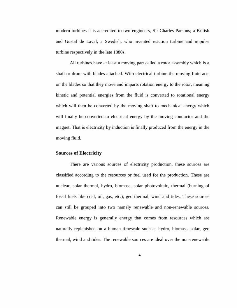
Fig.1.1: Global Cumulative Installed Wind Capacity 1996-2010 Information from
(GWEC, 2010, p.14)
Over the course of 2010 many countries, most notably China, have
dramatically increased their number of wind installations (GWEC, 2010, p.11).
Denmark has about 100% of their electrical energy from wind and they have not
being facing any electrical power challenges so far and over 83 countries around
the world are using wind power to supply the electricity grid.
Wind Turbine
The wind turbine is a mechanical device with a rotary part that converts
the wind‘s energy (potential and kinetic) to electrical energy. There are two
classifications of wind turbine; the airborne wind turbine and the grounded/tower

7
wind turbine. An airborne wind turbine is a design concept for a wind turbine that
is supported in the air without a tower, thus benefiting from the higher velocity
and almost constant wind at high altitudes, while avoiding the expense of tower
construction, or the need for slip rings or yaw mechanism. There are two varieties
of the airborne wind turbine namely, the aerodynamic variety and the aerostat
variety. Currently airborne wind turbines are under research and there is no
airborne wind turbine in commercial use. The grounded/tower wind turbine is
directly or indirectly connected to the ground or suspended on water. There are
also two types, which are the horizontal axis wind turbine (HAWT) and vertical
axis wind turbine (VAWT). Following are the types.
Fig.1.2: Vertical Axis Wind Turbine Fig.1.3: Horizontal Axis Wind Turbine
(VAWT) (HAWT)
8
There are also two types of the vertical axis wind turbines which are the
Darrieus and the Savonius, which are actually different with respect to the design
of the rotor/blades.
Energy challenges in Ghana
The economy of Ghana is growing, so is its population and energy
dependency. This pose challenges to the country with regard to its ability to
provide affordable and reliable electric power. Ghanaians are only able to access
less than 72% of electricity, which is a hindrance to sustainable development
(Essandoh, 2012). Currently, load shedding has been going on in various parts of
Ghana due to the energy crisis. There are even sometimes that the whole country
is cut out of electric supply. This erratic power supply is a big blow to the country
and as a result, hinders development and growth of the country, productivity and
economic activity have also declined for the past decade.
Statement of problem
In view of the current energy crisis in Ghana and also persistence increase
in fuel prices and utility charges, it is necessary for the nation to consider
exploring the wind energy resource to diversify, sustain and save the energy
production crisis in Ghana, increase access to electricity and as well, improve the
reliability of power supply and make it more affordable, and then provide energy
9
security for Ghana. Hence, the construction of the prototype wind turbine to meet
the energy demands.
Aim of Study
To design a wind turbine.
To construct a prototype of the design with simple, common and cheap
materials around.
To take current and voltage values at varied wind speeds with the
prototype and hence compute the power outage of the turbine.
Scope of Work
The study contains five chapters: the introduction thus chapter 1examines
the backgrounds, the wind, methods and sources of electricity. It also introduces
the subject of study in brief and then outlines the organization of the rest of the
research.
Chapter 2 (Literature Review) The purpose of this chapter which is to
present a review of current literature, arguments and mathematical theories related
to the wind turbine and linking existing studies to the current study. The
mathematics and physics of the rotor (blades), stator (coil windings and magnets
component) and all parts of the wind turbine are explained and related to the wind
energy and speed, and to the output. It also poses critics on the health and
environmental hazard of the wind turbine.
10
Chapter 3 (Design and Construction) illustrates the research design and
ideas, process and methods for building the prototype and data collections. The
rationale behind the choice of each tool and the methods of analyzing the data is
elaborated. The objective of Chapter 3 is to illustrate the research design and
report the research and design processes of the study.
In chapter 4 (Analysis of Results), there is presentation and discussion of
the results by using different research instruments and methods. The results of the
quantitative and qualitative research conducted are presented and juxtaposed with
other literature available.
Chapter 5 is the conclusion of the study. In this, there is review of
significant findings and recommendations, especially to the Energy Commission
of Ghana, the Ghanaian community and to future researchers as to how wind
energy can be utilized into electrical energy, to curb the energy crisis in the
country.
11
CHAPTER TWO
LITERATURE REVIEW
Overview
The principles and the actual theories and ground work that goes into the
making or manufacture and working of the wind turbine is what this chapter is
about. The working of the wind turbine to produce electricity involves a lot of
processes and choices as well, taking into consideration the blades, coil windings,
magnets and the choice of materials used etc. The mathematics and physics is
taking into play to explain all the concepts at hand. Also the positive and negative
impact of wind turbine is also discussed. The review will be started by first
talking about the wind.
Wind Speed Variation
Most of the power harness from the wind is as a result of its speed. The
instrument used to measure wind speed is called, Anemometer. However, the
nature of wind‘s speed is such that its direction, speed, and temperature vary. The
four main categories of wind variation are;
Variation with time; since winds are generated by difference in temperature of
air between two locations, it is subject to heat from sunshine and the temperature
of the surrounding in an area of the Earth. The variation can be momentary, daily,
and seasonal.
12
Variation with height; the speed of the wind changes with height, normally at
higher heights the speed of the wind is greater. Thus the higher the height from
the surface of earth the higher the wind speed.
Variation with terrain; the speed of the wind is influence by all obstructions that
lies on its path, which tends to slow it down. Example trees, buildings, etc.
Variation with geography; the speed of the wind is affected by the climate at
region which is attributed to the geographical location (Hemani, 2012).
Power of the Wind
The amount of energy that can be captured from the wind is exponentially
proportional to the speed of the wind and it is known to be a function of the cube
of the wind speed. Thus power available from the wind varies as the cube of the
wind speed, so twice the wind speed means eight times the power. This is why
sites for wind turbine has to be selected carefully. (Hansen, 2008)
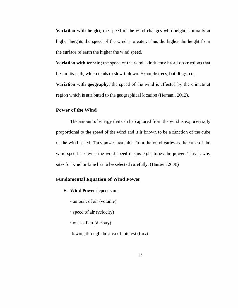
Fundamental Equation of Wind Power
Wind Power depends on:
• amount of air (volume)
• speed of air (velocity)
• mass of air (density)
flowing through the area of interest (flux)
13
Kinetic Energy definition:
• KE = ½ * m * v2
Power is KE per unit time:
thus power in terms of rate of change of mass flow
• P = ⁄ *
* v
2
Fluid mechanics gives mass flow rate (density * volume flux):
thus rate of change of mass of the air flowing over a blade surface area A,
perpendicular to the direction of wind flow can be determined as;
•
= ρ* A * v
Therefore the power that can be harness in the wind can be theoretically
expressed as;
• P = ½ * ρ * A * v 3 i.e. if the turbine is perfectly efficient.
=> Wind Power Pw = (air density)*(rotor swept area A= πr2)*(cube of
velocity)
Efficiency in Extracting Wind Power
Betz Limit & Power Coefficient:
Since no machine is 100% efficient, a turbine cannot necessarily capture
all of the power in the wind passing over its blades. It can only absorb a portion of
it. There is a maximum value that no turbine in its best performance can exceed. It
14
can be theoretically determined and is called the Betz limit. The value for Betz
limit is 16/27 = 0.59 or 59% efficiency.
Power Coefficient, CP, is the ratio of power extracted by the turbine, PT
to the total power contained in the wind resource, PW.
CP=PT / PW
=> Cp= PT/(½ρAV3)
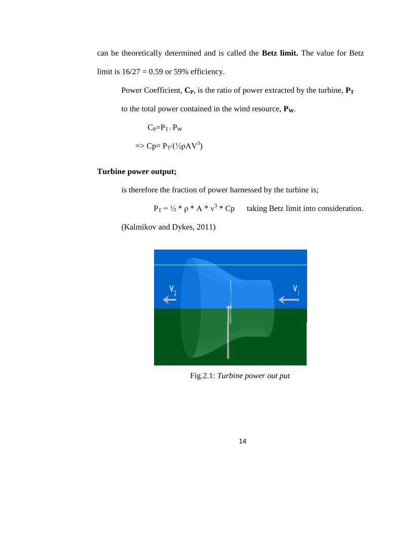
Turbine power output;
is therefore the fraction of power harnessed by the turbine is;
PT = ½ * ρ * A * v3 * Cp taking Betz limit into consideration.
(Kalmikov and Dykes, 2011)
Fig.2.1: Turbine power out put
15
Faraday’s Law of Electromagnetic Induction and Lenz Law
By defining magnetic flux as Φ = BAcosθ, where θ is the angle between B
and the direction perpendicular to the plane of the loop (along the axis of the
loop), Faraday's law states that the emf induced in a wire is proportional to the
rate of the flux through the loop. Mathematically as;
Ԑ =
a little modification of the law gives Lenz law, which states that the
direction of any induced current (or induced emf) will be such as to produce
effects which oppose the change that produces it.
Ԑ = -N
The N attributes to the number of turns of the conductor.
Substituting the magnetic flux relation into equation
Ԑ = -N
For a loop rotating periodically relative to a constant magnetic field, θ =
ωt, Where ω is the angular speed.
Ԑ = ωNBAsinωt
Then the maximum emf is,
εmax =ωNBA
(Serway & Beicher, 2000).
16
The magnetic field B can be expressed in teams the permeability μ and the
distance of separation, d from Ampere‘s law (Kraus, 1992) as;
B(at 𝑑) =
The permeability of in this relation is an important characteristic of the
magnetic core material for the wire loop. The relative permeability μr is often
used to refer to the magnetic property of materials. Air has relative permeability
of 1.000 comparable to that of vacuum are paramagnetic material including
aluminium. Diamagnetic material, example copper, has relative permeability in
the order of 0.99990 to 0.99999, and ferromagnetic materials, example steel, Iron
(0.2) impurity, has an μr value in the order of 1,000 to 100,000 (Yong, 2008).
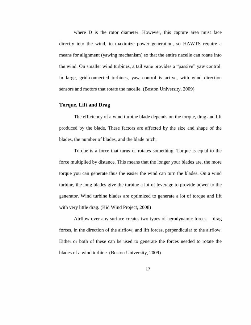
Wind Turbine Aerofoil
Modern HAWTs usually feature rotors that resemble aircraft propellers,
which operate on similar aerodynamic principles, i.e., the air flow over the airfoil
shaped blades creates a lifting force that turns the rotor. The nacelle of a HAWT
houses a gearbox and generator. HAWTS can be placed on towers to take
advantage of higher winds farther from the ground.
The capture area of a HAWT, the area over which the sweeping blades can
―capture‖ the wind, is given by
A= (D/2)2
17
where D is the rotor diameter. However, this capture area must face
directly into the wind, to maximize power generation, so HAWTS require a
means for alignment (yawing mechanism) so that the entire nacelle can rotate into
the wind. On smaller wind turbines, a tail vane provides a ―passive‖ yaw control.
In large, grid-connected turbines, yaw control is active, with wind direction
sensors and motors that rotate the nacelle. (Boston University, 2009)
Torque, Lift and Drag
The efficiency of a wind turbine blade depends on the torque, drag and lift
produced by the blade. These factors are affected by the size and shape of the
blades, the number of blades, and the blade pitch.
Torque is a force that turns or rotates something. Torque is equal to the
force multiplied by distance. This means that the longer your blades are, the more
torque you can generate thus the easier the wind can turn the blades. On a wind
turbine, the long blades give the turbine a lot of leverage to provide power to the
generator. Wind turbine blades are optimized to generate a lot of torque and lift
with very little drag. (Kid Wind Project, 2008)
Airflow over any surface creates two types of aerodynamic forces— drag
forces, in the direction of the airflow, and lift forces, perpendicular to the airflow.
Either or both of these can be used to generate the forces needed to rotate the
blades of a wind turbine. (Boston University, 2009)
18
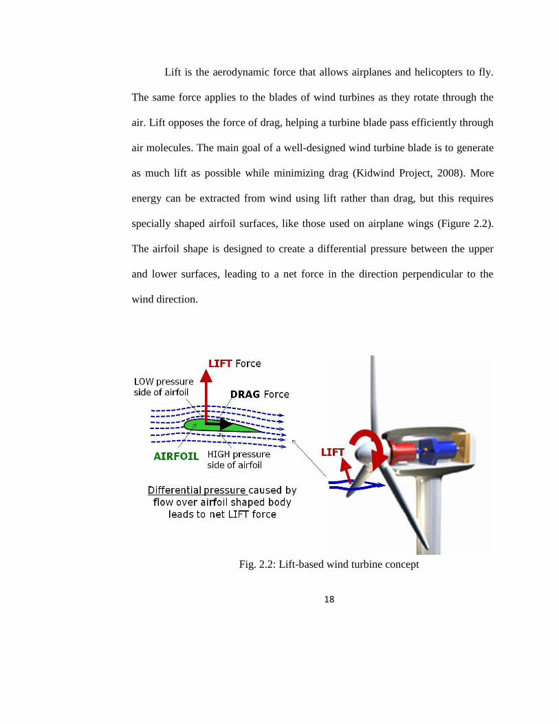
Lift is the aerodynamic force that allows airplanes and helicopters to fly.
The same force applies to the blades of wind turbines as they rotate through the
air. Lift opposes the force of drag, helping a turbine blade pass efficiently through
air molecules. The main goal of a well-designed wind turbine blade is to generate
as much lift as possible while minimizing drag (Kidwind Project, 2008). More
energy can be extracted from wind using lift rather than drag, but this requires
specially shaped airfoil surfaces, like those used on airplane wings (Figure 2.2).
The airfoil shape is designed to create a differential pressure between the upper
and lower surfaces, leading to a net force in the direction perpendicular to the
wind direction.
Fig. 2.2: Lift-based wind turbine concept
19
Rotors of this type must be carefully oriented (the orientation is referred to
as the rotor pitch), to maintain their ability to harness the power of the wind as
wind speed changes (Boston University, 2009). The amount of lift a blade or wing
can generate is determined by several factors—the shape of the blade, the speed
of the air passing around the blade, and the angle of the blade relative to the
apparent wind. Almost all HAWT make use of lift force for the rotation of their
blades.
Drag, or air resistance, is a force that is working against the blades, caus-
ing them to slow down. Drag is always important when an object moves rapidly
through the air or water. Airplanes, race cars, rockets, submarines, and wind
turbine blades are all designed to have as little drag as possible. Drag increases
with the area facing the wind—a large truck has a lot more drag than a
motorcyclist moving at the same speed. Wind turbine blades have to be
streamlined so they can efficiently pass through the air. Changing the angle of the
blades will change the area facing the apparent wind. This is why blade pitch
angles of 10-20 degrees tend to have much less drag than greater angles.
Drag also increases with wind speed. The faster an object moves through
the air, the more drag force it experiences. This is especially important for wind
turbine blades, since the blade tips are moving through the air much faster than
the base of the blade. The shape and angle of wind turbine blades changes along
the length of the blade to reduce drag at the blade tips.
20
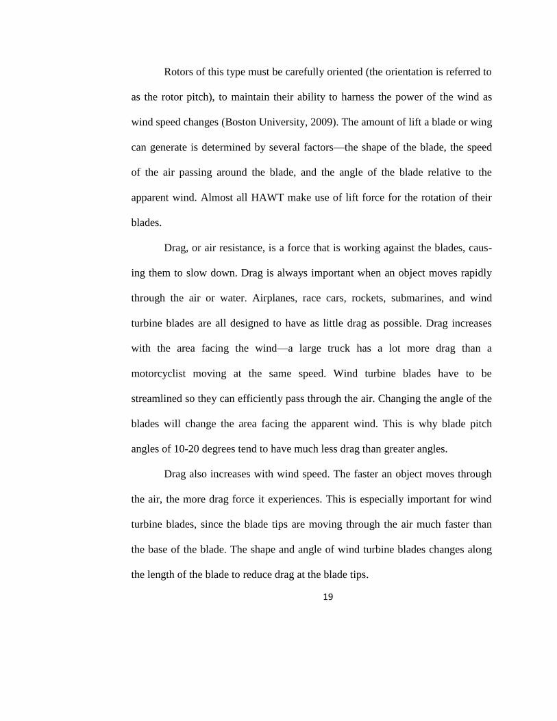
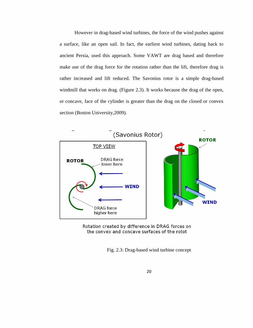
However in drag-based wind turbines, the force of the wind pushes against
a surface, like an open sail. In fact, the earliest wind turbines, dating back to
ancient Persia, used this approach. Some VAWT are drag based and therefore
make use of the drag force for the rotation rather than the lift, therefore drag is
rather increased and lift reduced. The Savonius rotor is a simple drag-based
windmill that works on drag. (Figure 2.3). It works because the drag of the open,
or concave, face of the cylinder is greater than the drag on the closed or convex
section (Boston University,2009).
Fig. 2.3: Drag-based wind turbine concept
21
Static Velocity and Static Torque:
1. Start-up wind speed is the lowest wind speed at which the torque spins. It
depends on turbines design and construction.
2. Static torque is the torque of the wind applied about the centre of the rotor
when it is stationary. A high static torque indicates a low start-up wind
speed. (Weiss, 2010).
Tip Speed Ratio
The Tip Speed Ratio (TSR) is an extremely important factor in wind
turbine design. TSR refers to the ratio between the wind speed and the speed of
the tips of the wind turbine blades. Thus relationship between rotor blade velocity
and relative wind velocity, is the foremost design parameter around which all
other optimum rotor dimensions are calculated:
λ = Ωr⁄Vw
Vw = Windspeed
r = Radius
Ω = Rotational velocity (rad/s)
λ = Tip speed ratio
If your rotor spins too slowly, a lot of wind will pass through the gaps
between the blades rather than giving energy to your turbine. But if your blades
22
spin too quickly, they could create too much turbulent air or act as a solid wall
against the wind therefore a correct TSR should be considered when designing
wind turbine.
Aspects such as efficiency, torque, mechanical stress, aerodynamics and
noise should be considered in selecting the appropriate tip speed. The efficiency
of a turbine can be increased with higher tip speeds, although the increase is not
significant when considering some penalties such as increased noise, aerodynamic
and centrifugal stress. (Schubel and Crossley, 2012)
Number of blades
Efficiency of power extraction depends on the proper choice of the
number of blades. That is the limitation on the available power in the wind means
that the more blades there are, the less power each can extract. This is because
when the blades are close to each other, every blade will move in a turbulent air
cause by the preceding blade under fast rotation speed. Power extraction will be
minimized. It will also be less than the optimum if the blades are so far apart or
move so slowly that much of the air stream passes through the wind turbine
without interacting with the blade. Thus, the number of blades should depend on
TSR. To achieve optimum efficiency, the TSR is kept high by minimizing the
number of blades. Generally, only two or three blades are required (Tiwari et al,
23
2010). A consequence of this is that each blade must also be narrower to maintain
aerodynamic efficiency. (WE Handbook)
Low tip speed ratios produce a rotor with a high ratio of solidity, which is
the ratio of blade area to the area of the swept rotor. It is useful to reduce the area
of solidity as it leads to a decrease in material usage and therefore production
costs (Schubel and Crossley, 2012). Meaning, less blades less material usage and
less cost.
Solidity of Wind Turbine
The solidity, σ of a wind turbine rotor is the ratio of the projected blade
area to the area of the wind intercepted. That is, BA ⁄2Aint. Where, B is the
number of blades, A is area swept by wind on a blade, Aint is the total area the
wind intercept with turbine blades. For a multiple blade water-pumping windmill,
it is typically around 0.7. For high-speed horizontal axis machines, it lies between
0.01 and 0.1; for the Darrieus rotor also it is of the same order. Solidity has a
direct relationship with the torque and speed. High-solidity rotors have high
torque and low speed, and are suitable for pumping water. Low-solidity rotors, on
the other hand, have high speed and low-torque, and are typically suited for
electrical power generation. (Tiwari, P, Swain, D, and Kumar, K. A,2010).
24
The Generator, Gear Box and Gears
The generator converts the power from the rotating rotor shaft to electrical
power, which can be used on site, or be sent into the electrical grid (the system
that interconnects power plants, electrical distribution networks, and electrical
power users). Generators are used in all electrical power plants, including coal
and oil-fired plants. A generator can be thought of as an electric motor run in
reverse; in fact, many motors can also be used as generators. It contains the
magnets and the conductor (wire) that does the main work (induction).Typical
generators operate with a rotation speed of 1000 to 3600 revolutions per minute
(rpm). These speeds are far too fast for a wind turbine for several reasons,
including excessive stress and turbulence at high speeds and the fact that the tip
speed is limited by the speed of sound (340.3 m/s) due to both excessive drag and
noise caused by shock wave formation. The gear box solves the problem, by
converting the low speed rotation of the wind turbine rotor (typically less than
100 rpm) to the high rpm needed by the generator (Boston University, 2009). A
gear is a wheel with grooves (teeth) engraved on the outer circumference, such
that two such devices can interlock and convey motion from one to the other
while the gear box is a transmission containing the train of gears and to which a
gear lever is connected.
25
The Magnet and Conductor
This is the main component of the generator and hence the turbine. Since
the electricity is produced by the induction which is as a result of relative
movement of these two components. In fact in order to induce a high
electromotive force a magnet with high magnetic flux/density should be
considered and a higher number of turns for the conductor/wire. The wire most
preferably copper because of its high conductivity and resistance to rust is coated
or enameled. It is best that a lower gauge number (i.e. thicker wire) is used in
order to reduce the resistance and give way for higher emf and hence power,
from;
Resistivity, ρ =
Where R is resistance
A is cross sectional area
l is length
R =
so as A increases (i.e. thickness of wire) the lesser the resistance R
into V=IR, thus for a bigger voltage bigger current but smaller resistance as
from above. Therefore giving way for greater power output P=IV.
Blade Element Momentum Theory
The blade element momentum theory, BEM equates two methods of
examining how a wind turbine operates. That is:
26
1. By looking at the force generated,
2. By the effect of rotation of the turbine and wake system distribution
(i.e., torque) (Ingram, 2011).
Blade Element Theory
This theory is based on two assumptions:
1. There are no interactions between different blade elements.
2. The forces on the blade element solely Lift and drag.
If there are B number of blades, the area of turbine swept by wind A , the
relative velocity W, the flow angle ϕ, then for HAWT the trust T and torque τ
respectively are;
T=1/2BAρW2(CLsinϕ + CDcosϕ)
τ = ½ BRAρW2(CLsinϕ – CDcosϕ)
The effect of the drag force is clearly seen in the equations, an increase in
thrust force on the machine and a decrease in torque (and power output). For
VAWT the torque;
τ = ½ BRAρW2(CLcosϕ + CDsinϕ)
From the above equation, the effect of drag force rather increases the
torque as seen in equation (Igram, 2011). This is why Drag-Based turbine is
27
preferred for application that required direct mechanical work. Example, wind
turbine made for corn mill (Weiss, 2010). 27
Savonius Wind Turbines
Savonius turbines are one of the simplest and easy to construct turbines.
This is why it was chosen for this project. Aerodynamically, they are drag-base
type of vertical axis wind turbine consisting of two scoop or three scoops.
Because of the curvature, the scoops experience less drag when moving against
the wind than when moving with the wind. The differential drag causes the
Savonius turbine to spin. Because they are drag-type devices, Savonius turbines
extract much less of the wind's power than other similarly-sized lift-type turbines.
Much of the swept area of a Savonius rotor is near the ground, making the overall
energy extraction less effective due to lower wind speed at lower heights (Weiss,
2010).
28
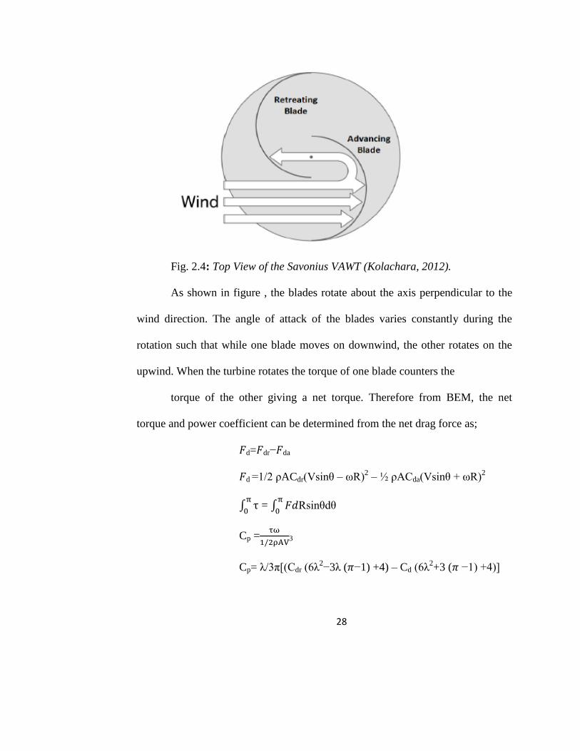
Fig. 2.4: Top View of the Savonius VAWT (Kolachara, 2012).
As shown in figure , the blades rotate about the axis perpendicular to the
wind direction. The angle of attack of the blades varies constantly during the
rotation such that while one blade moves on downwind, the other rotates on the
upwind. When the turbine rotates the torque of one blade counters the
torque of the other giving a net torque. Therefore from BEM, the net
torque and power coefficient can be determined from the net drag force as;
𝐹d=𝐹dr−𝐹da
𝐹d =1/2 ρACdr(Vsinθ – ωR)2 – ½ ρACda(Vsinθ + ωR)
2
∫
= ∫ 𝐹𝑑
Rsinθdθ
Cp =
3
Cp= λ/3π[(Cdr (6λ2−3λ (𝜋−1) +4) – Cd (6λ
2+3 (𝜋 −1) +4)]
29
From this equation, Cp can be expressed as a function of the drag
coefficients and the tip speed ratio (Menet as cited in Kolachara, 2012).
Different Modification of Savonius Wind Turbine
The height of the shaft together with the blade is increase to increase the
capacity of wind capture. This is equivalent to increasing the length of the
cylindrical sections, if all the sections are aligned.
Alternatively a second set can be installed at 90° from the first half
cylinders. This adds to the uniformity of rotational torque on the shaft, since with
only two half cylinders the absorbed power pulsates (this is not uniform as the
rotor turns).
A gap is in the structure where the two half cylinders are joined. This
allows the air to pass through this gap from the segment capturing wind to the
segment opposing wind. The advantage is two-fold: wind is not trapped in the
capturing blade and has a more steady flow, and the opposing blade has an extra
force to help it push the air. This is the most efficient Savonius design because it
has the advantage of air being deflected twice, also the vanes act partly like an
airfoil when they are edge-on into the wind, creating a small lift effect and thus
enhancing efficiency
The other design arranges the two blades to be able to swing about an axis
at their outer edges. This arrangement can greatly decrease the resistance to the air
30
flow of the opposing blade. Both of these designs enhance the power coefficient,
and thus the capacity of a turbine for the same size, but introduce their own
complexities.
Another design for a Savonius rotor alteration is to twist each of the half
cylinders. This helps the captured power to be more uniform rather than pulsating
(Hemani, 2012).
Why Wind Energy
As discussed above in chapter one, there are several forms of generating
electricity so why should wind energy be preferred to the others? The following
discusses the reason for this venture.
Free Fuel (Cheap)
Unlike other forms of electrical generation where fuel has to be purchased
at high cost before converting to electricity, like; coal, crude oil, gas, nuclear etc
and shipped or transported to a processing plant, wind energy generates electricity
at the source of fuel, which is free. Wind is a native fuel that does not need to be
mined or transported, thus rolling out two important expensive costs out of long
term energy expenses. Making the final product thus electricity from wind less
expensive than the others. (windustry.org)
31
Price Stability and Fewer Subsidy
Since electricity from wind is rather cheaper than the other forms,
electricity is made available to the public at lower fee and since there no fuel
increase and transportation cost related to wind energy the electrical power will
remain forever stable. And also fewer subsidies are needed to support wind
energy compared to the subsidies to the other forms of energy. According to
Renewable Energy World magazine, conventional energy receives US$ 300
billion in subsidies per year, while renewable energy has received less than US$
20 billion of tax-payers‘ money in the last 30 years (windustry.org). In a country
like Ghana, where cost of fuel and transport keeps springing up every now and
then, causing increase in utility bills and hardship wind energy generation will be
the best option for us.
Environmental Friendly (very less pollution)
It is a fact that energy use in power plants accounts for 67% of Sulfur
Dioxide (SOB2B), the primary cause of acid rain. SOB2B causes acidification of
lakes and damages forests, crops, animals and other habitats. Then 25% of
Nitrous Oxide (NOx), which causes smog and respiratory ailments. Also 33% of
Hg (mercury), a persistent, bio-accumulative toxin which increases in
concentration as it moves up the food chain which is example from fish to birds,
causing serious deformities and nerve disorders.
32
Wind turbine one of the best choice that we have because it has no
harmful emissions such as Sulfur Dioxide (SOB2B), Nitrous Oxide (NOx), or
Mercury emissions. Also it does not have Greenhouse Gas Emissions. It also
don‘t need any cooling mechanism like cooling water that we always use at fuel
engines and nuclear reactors. There are water pollution that is always generated
by mining activities. After all there is no waste when using wind turbine.
Land conserved, Supports Agriculture
Wind power has the advantage of not being land intensive. Wind farms
generally require 0.08-0.13 km2/MW of generation capacity, (Andersen, 2008,
p.12) unlike mining of coal for power generation, where the land is damaged or
hydroelectric dam where a vast land has to be forfeited for water build-up and
retention. The land surrounding the wind turbines can remain as natural habitat or
agricultural land (Andersen, 2008, p.12). Many of the materials wind turbines are
made of can be recycled, and no decommissioning issues are associated with wind
turbines (Andersen, 2008, p.11). Wind turbines can therefore be installed amid
cropland without interfering with people, livestock or production.
Wind Energy and Jobs
The Conference Board of Canada has estimated, based on a 2000 MW
generating capacity, that the development and operation of offshore wind farms in
Ontario has the potential to create 3 900- 4 000 jobs during the construction
33
phase, from 2013-2026 (Conference Board of Canada, 2010). This development
would contribute between $4.8 and $5.5 billion to Ontario‘s economy for this
period (Conference Board of Canada, 2010).
The development of wind energy in Europe has created many new jobs. In
2007 in the European Union the wind energy sector directly employed 108 600
people, and indirectly employed over 150 000 (EWEA, 2008, p.13). It is expected
that by 2030 the number of people employed by the wind energy sector will have
risen to 375 000 (EWEA, 2008, p.11).
Work Safety
There are no risk factors like effect of heat and burns from boilers or
nuclear emission effects for the workers. Also no respiratory diseases and
infertility associated because of no harmful emission and excessive engine heat
respectively.
Wind Energy Issues
Above all these benefits wind energy is also noted for very few issues
which are as follows;
Infrasound
Concerns have been raised about human exposure to ―low frequency
sound‖ and ―infrasound‖ from wind turbines. There is no scientific evidence,
34
however, to indicate that low frequency sound generated from wind turbines
causes adverse health effects.
Low frequency sound and infrasound are everywhere in the environment.
They are emitted from natural sources (e.g. wind, rivers) and from artificial
sources including road traffic, aircraft, and ventilation systems. The most
common source of infrasound is vehicles which we are found of everywhere.
Under many conditions, low frequency sound below 40Hz from wind turbines
cannot be distinguished from environmental background noise from the wind
itself (Leventhall 2006, Colby et al 2009).
“The sound level from wind turbines at common residential setbacks is not
sufficient to cause hearing impairment or other direct health effects…” (King,
2010 p.2)
Visual Effects
Wind turbines are just normal structures to look at, just like trees, better
looking than boiler chimneys and open cast coal mine. Wind farms have relatively
little visual effect but however some people find it to be boring to look at. Drivers
also complain of them being disturbing. However manufacturers have than a lot to
this issue such as painting of turbine with neutral colours, arranging of turbine in
visually pleasing manner and also designing each turbine uniformly. Wind farms
are also situated far from road networks and residential areas.
35
Shadow Flicker Effects
Shadow flicker occurs when the blades of a turbine rotate in sunny
conditions, casting moving shadows on the ground that result in alternating
changes in light intensity appearing to flick on and off. Some people find these
shadows distasteful, about 3 per cent of people with epilepsy are photosensitive,
generally to flicker frequencies between 5-30Hz. Most industrial turbines rotate at
a speed below these flicker frequencies. This effect can however be prevented
with proper placement of wind turbines to avoid the particular setup necessary to
create this effect.
Electromagnetic Effects
Electromagnetic radiations are all around us, in fact they are ubiquitous
since every electronic gadget emits them and the earth also naturally emits them
around. To top up, wind turbines are 80 to 100 metres above the ground so any
emf produced will be far from any person around and the cables that carry the
power are underground thus no emf. However there are still some effects like
radio frequency and radar interference.
Wind Resource and Measurements in Ghana
Many studies have gone into Wind Energy assessment in Ghana by
renewable energy analysts and groups of researchers. Data has been compiled and
analysed by researching institutions such as Ghana Meteorological Agency
36
(GMA) and Energy Commission (EC). It has been observed that wind energy
generation are possible in some parts of the country, especially, along the coast, as
an alternate supplement to the hydro-electric power and for off-grid applications.
The monthly average wind speed for the identified potential sites along the coast,
ranges from 4.8 to 5.5 m/s. Across the country, Ghana is observed to have class 3
to class 6 wind resource, that is 6.4 m/s to 8.8 m/s wind speed. (energy
commission website)
37
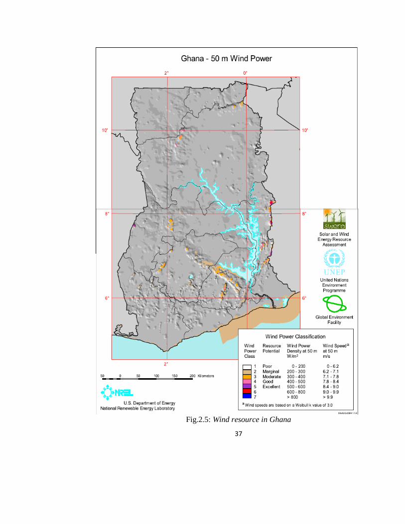
Fig.2.5: Wind resource in Ghana
38
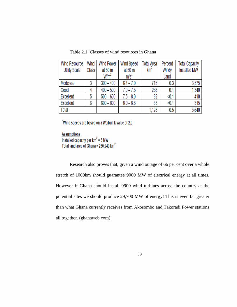
Table 2.1: Classes of wind resources in Ghana
Research also proves that, given a wind outage of 66 per cent over a whole
stretch of 1000km should guarantee 9000 MW of electrical energy at all times.
However if Ghana should install 9900 wind turbines across the country at the
potential sites we should produce 29,700 MW of energy! This is even far greater
than what Ghana currently receives from Akosombo and Takoradi Power stations
all together. (ghanaweb.com)
39
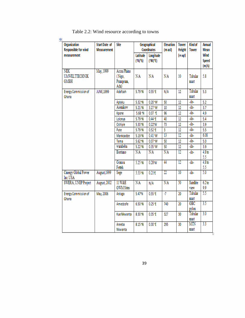
Table 2.2: Wind resource according to towns

40
This and many available facts and research proves Ghana has enough wind
resources and should therefore take steps in harnessing it to save our current
energy crisis.

41
CHAPTER THREE
DESIGN AND CONSTRUCTION
Overview
This is the chapter that talks about the design, process and methods for the
construction of the project. To make the savonius prototype turbine as potable as
possible while gunning on high efficiency, all the choices, processes and materials
used were taken into strict considerations. All the processes, materials and tools
applied to achieve the optimum design are what this chapter covers.
Items and Materials Needed
The following materials were used in the construction of the prototype
wind turbine;
Connecting hollow metal pipes and joints.
Plywood about 50cmx30cm
2 Plastic small buckets (about 20cm diameter)
Long hollow rod/pipe
19 AWG enamel wire (about 1kg)
1 Big speaker magnet
Carton
Adhesive tape
Glue

42
LED
Flexible wire
Screws, bolts, nuts and washers
Fig.3.1: Materials Needed
Tools Needed
The following tools were also applied in the building of the project;
Measuring tape
Hacksaw blade
Screwdrivers
Ammeter/Voltmeter
Pipes Plywood
Carton
Magnets Screws, bolts & nuts
Enamel wire
43
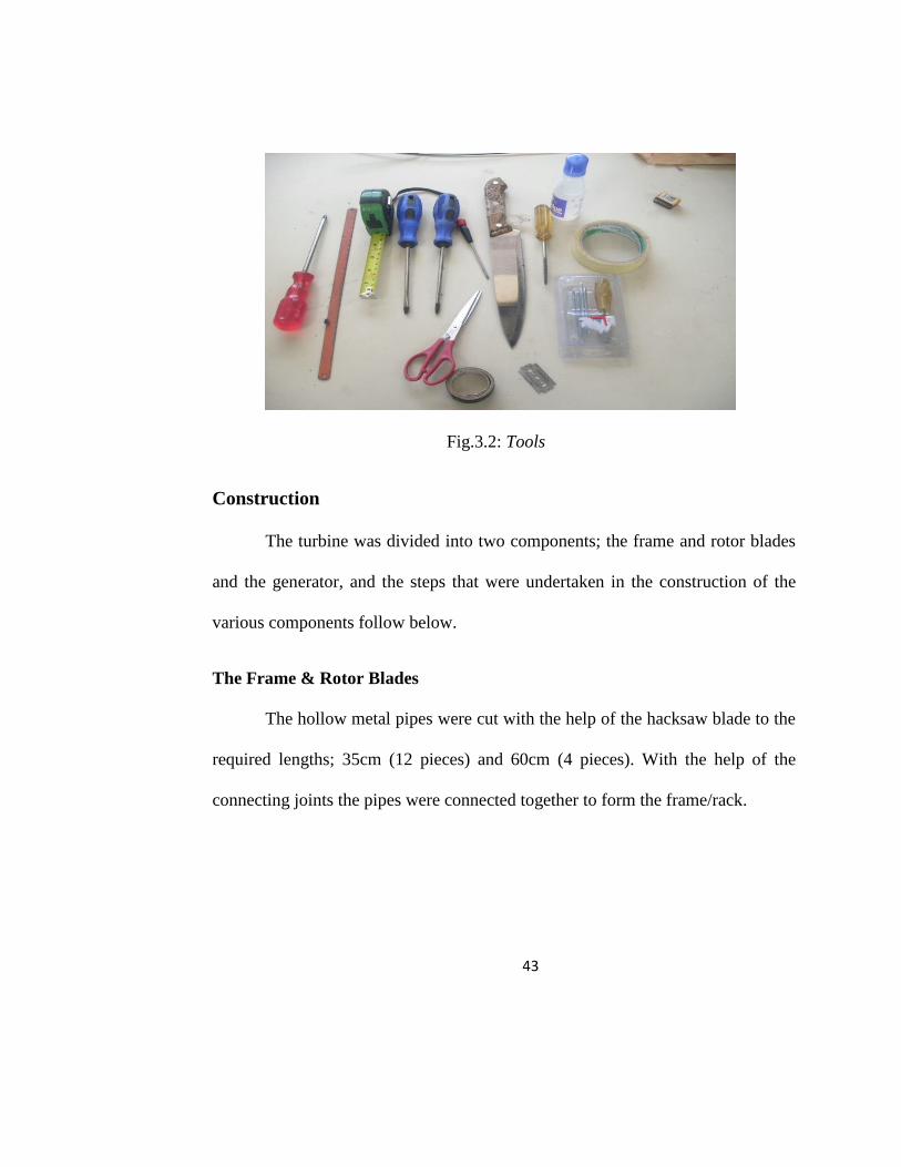
Fig.3.2: Tools
Construction
The turbine was divided into two components; the frame and rotor blades
and the generator, and the steps that were undertaken in the construction of the
various components follow below.
The Frame & Rotor Blades
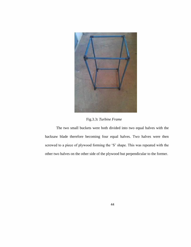
The hollow metal pipes were cut with the help of the hacksaw blade to the
required lengths; 35cm (12 pieces) and 60cm (4 pieces). With the help of the
connecting joints the pipes were connected together to form the frame/rack.
44
Fig.3.3: Turbine Frame
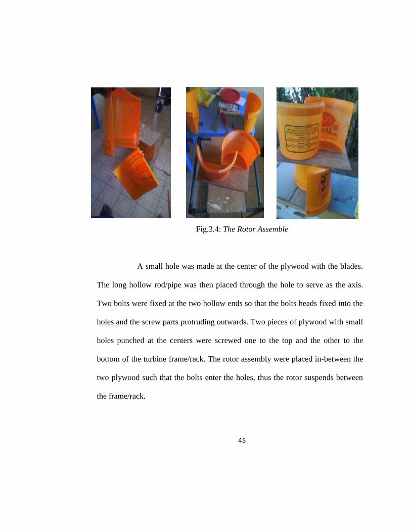
The two small buckets were both divided into two equal halves with the
hacksaw blade therefore becoming four equal halves. Two halves were then
screwed to a piece of plywood forming the ‗S‘ shape. This was repeated with the
other two halves on the other side of the plywood but perpendicular to the former.
45
Fig.3.4: The Rotor Assemble
A small hole was made at the center of the plywood with the blades.
The long hollow rod/pipe was then placed through the hole to serve as the axis.
Two bolts were fixed at the two hollow ends so that the bolts heads fixed into the
holes and the screw parts protruding outwards. Two pieces of plywood with small
holes punched at the centers were screwed one to the top and the other to the
bottom of the turbine frame/rack. The rotor assembly were placed in-between the
two plywood such that the bolts enter the holes, thus the rotor suspends between
the frame/rack.
46
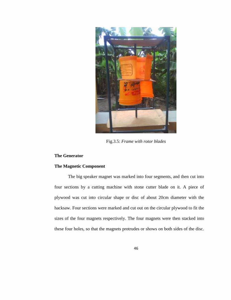
Fig.3.5: Frame with rotor blades
The Generator
The Magnetic Component
The big speaker magnet was marked into four segments, and then cut into
four sections by a cutting machine with stone cutter blade on it. A piece of
plywood was cut into circular shape or disc of about 20cm diameter with the
hacksaw. Four sections were marked and cut out on the circular plywood to fit the
sizes of the four magnets respectively. The four magnets were then stacked into
these four holes, so that the magnets protrudes or shows on both sides of the disc.
47
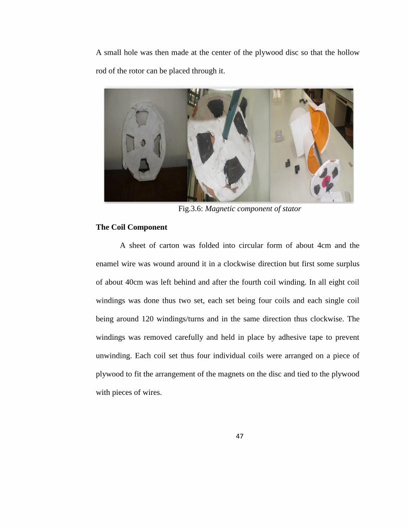
A small hole was then made at the center of the plywood disc so that the hollow
rod of the rotor can be placed through it.
Fig.3.6: Magnetic component of stator
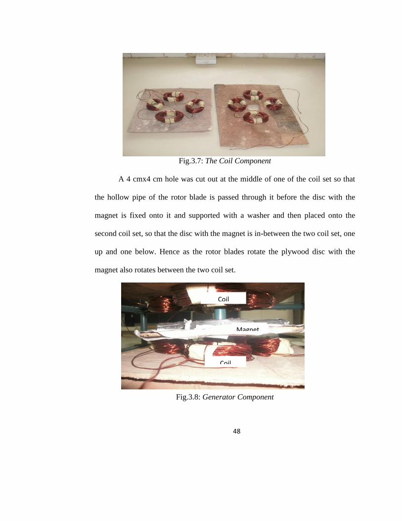
The Coil Component
A sheet of carton was folded into circular form of about 4cm and the
enamel wire was wound around it in a clockwise direction but first some surplus
of about 40cm was left behind and after the fourth coil winding. In all eight coil
windings was done thus two set, each set being four coils and each single coil
being around 120 windings/turns and in the same direction thus clockwise. The
windings was removed carefully and held in place by adhesive tape to prevent
unwinding. Each coil set thus four individual coils were arranged on a piece of
plywood to fit the arrangement of the magnets on the disc and tied to the plywood
with pieces of wires.
48
Fig.3.7: The Coil Component
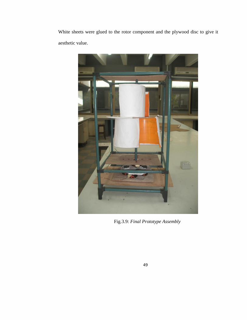
A 4 cmx4 cm hole was cut out at the middle of one of the coil set so that
the hollow pipe of the rotor blade is passed through it before the disc with the
magnet is fixed onto it and supported with a washer and then placed onto the
second coil set, so that the disc with the magnet is in-between the two coil set, one
up and one below. Hence as the rotor blades rotate the plywood disc with the
magnet also rotates between the two coil set.
Fig.3.8: Generator Component
Coil
Coil
Magnet
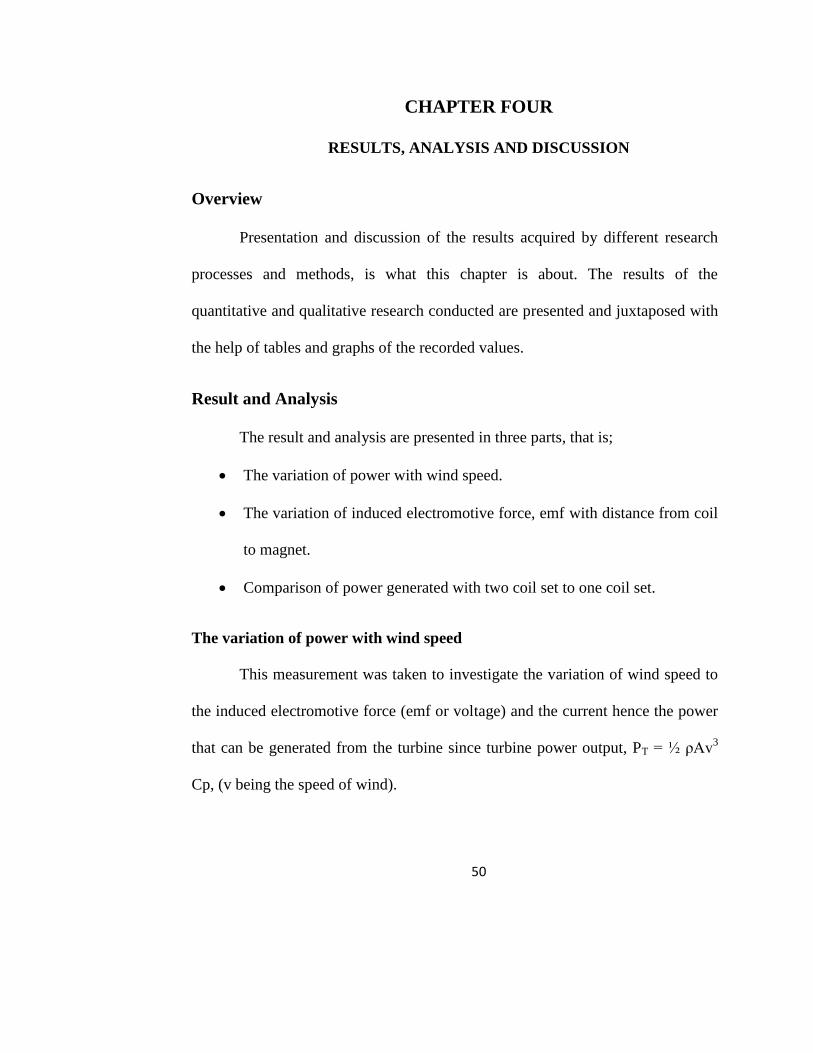
49
White sheets were glued to the rotor component and the plywood disc to give it
aesthetic value.
Fig.3.9: Final Prototype Assembly
50
CHAPTER FOUR
RESULTS, ANALYSIS AND DISCUSSION
Overview
Presentation and discussion of the results acquired by different research
processes and methods, is what this chapter is about. The results of the
quantitative and qualitative research conducted are presented and juxtaposed with
the help of tables and graphs of the recorded values.
Result and Analysis
The result and analysis are presented in three parts, that is;
The variation of power with wind speed.
The variation of induced electromotive force, emf with distance from coil
to magnet.
Comparison of power generated with two coil set to one coil set.
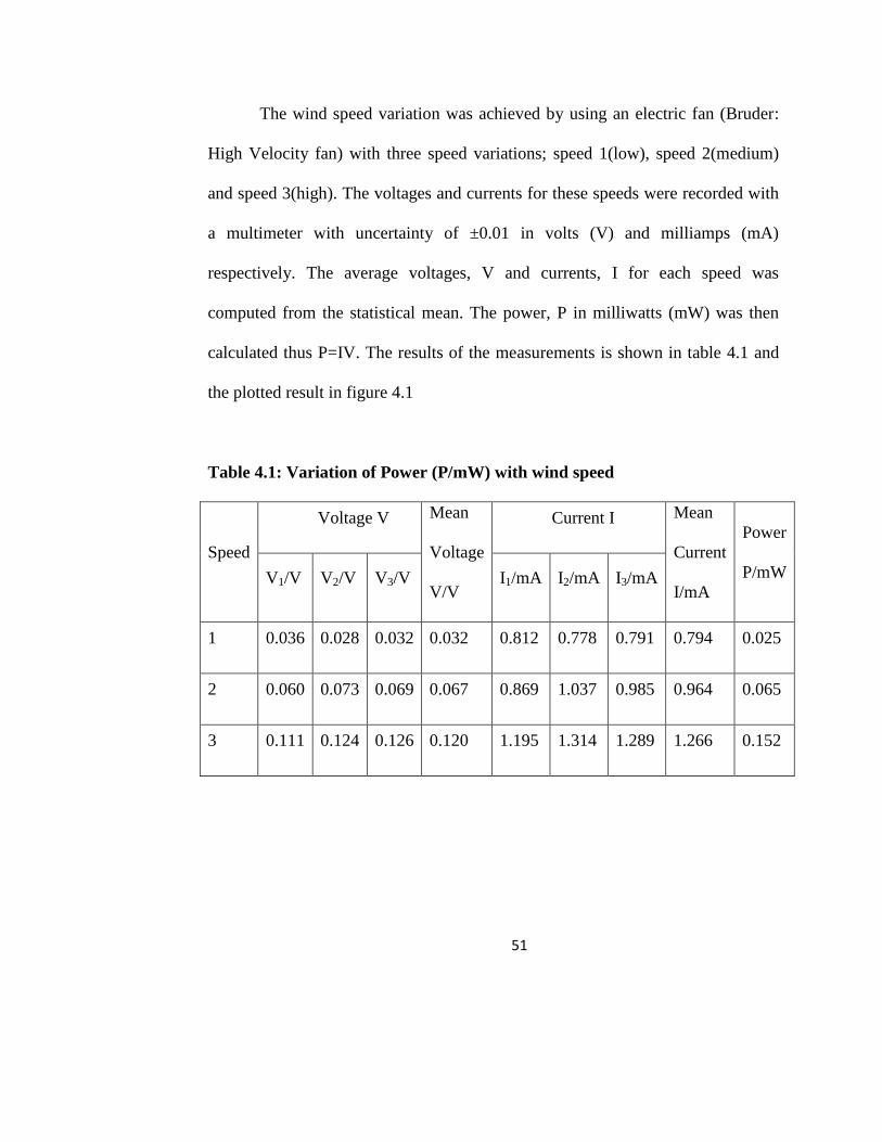
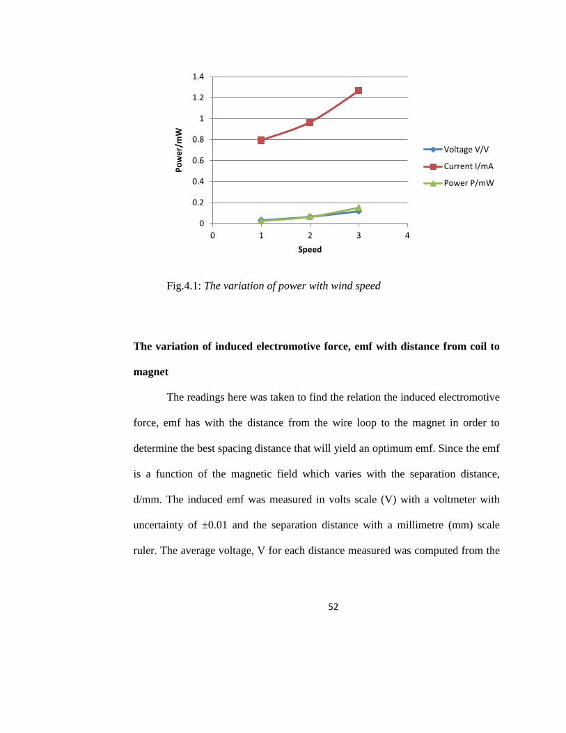
The variation of power with wind speed
This measurement was taken to investigate the variation of wind speed to
the induced electromotive force (emf or voltage) and the current hence the power
that can be generated from the turbine since turbine power output, PT = ½ ρAv3
Cp, (v being the speed of wind).
51
The wind speed variation was achieved by using an electric fan (Bruder:
High Velocity fan) with three speed variations; speed 1(low), speed 2(medium)
and speed 3(high). The voltages and currents for these speeds were recorded with
a multimeter with uncertainty of ±0.01 in volts (V) and milliamps (mA)
respectively. The average voltages, V and currents, I for each speed was
computed from the statistical mean. The power, P in milliwatts (mW) was then
calculated thus P=IV. The results of the measurements is shown in table 4.1 and
the plotted result in figure 4.1
Table 4.1: Variation of Power (P/mW) with wind speed
Speed
Voltage V Mean
Voltage
V/V
Current I Mean
Current
I/mA
Power
P/mW V1/V V2/V V3/V I1/mA I2/mA I3/mA
1 0.036 0.028 0.032 0.032 0.812 0.778 0.791 0.794 0.025
2 0.060 0.073 0.069 0.067 0.869 1.037 0.985 0.964 0.065
3 0.111 0.124 0.126 0.120 1.195 1.314 1.289 1.266 0.152
52
Fig.4.1: The variation of power with wind speed
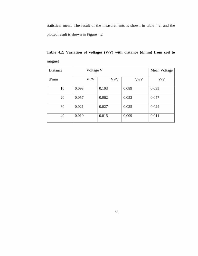
The variation of induced electromotive force, emf with distance from coil to
magnet
The readings here was taken to find the relation the induced electromotive
force, emf has with the distance from the wire loop to the magnet in order to
determine the best spacing distance that will yield an optimum emf. Since the emf
is a function of the magnetic field which varies with the separation distance,
d/mm. The induced emf was measured in volts scale (V) with a voltmeter with
uncertainty of ±0.01 and the separation distance with a millimetre (mm) scale
ruler. The average voltage, V for each distance measured was computed from the
0
0.2
0.4
0.6
0.8
1
1.2
1.4
0 1 2 3 4
Po
we
r/m
W
Speed
Voltage V/V
Current I/mA
Power P/mW
53
statistical mean. The result of the measurements is shown in table 4.2, and the
plotted result is shown in Figure 4.2
Table 4.2: Variation of voltages (V/V) with distance (d/mm) from coil to
magnet
Distance
d/mm
Voltage V Mean Voltage
V/V V1/V V2/V V3/V
10 0.093 0.103 0.089 0.095
20 0.057 0.062 0.053 0.057
30 0.021 0.027 0.025 0.024
40 0.010 0.015 0.009 0.011
54
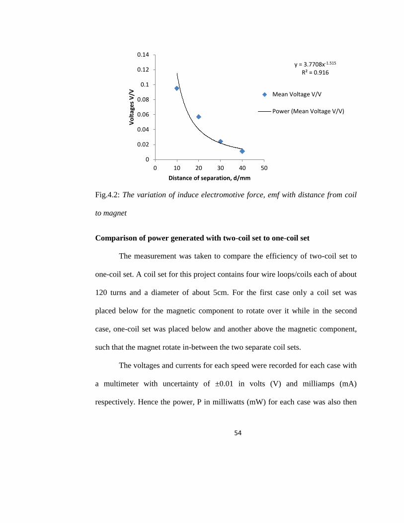
Fig.4.2: The variation of induce electromotive force, emf with distance from coil
to magnet
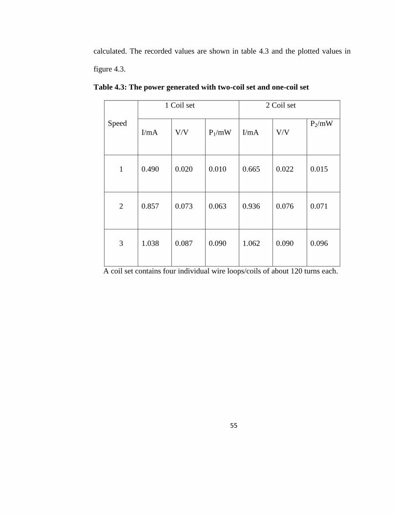
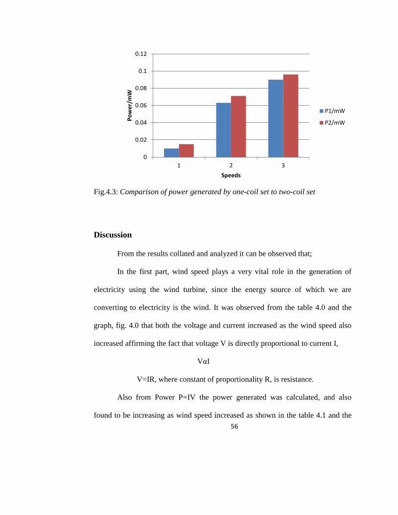
Comparison of power generated with two-coil set to one-coil set
The measurement was taken to compare the efficiency of two-coil set to
one-coil set. A coil set for this project contains four wire loops/coils each of about
120 turns and a diameter of about 5cm. For the first case only a coil set was
placed below for the magnetic component to rotate over it while in the second
case, one-coil set was placed below and another above the magnetic component,
such that the magnet rotate in-between the two separate coil sets.
The voltages and currents for each speed were recorded for each case with
a multimeter with uncertainty of ±0.01 in volts (V) and milliamps (mA)
respectively. Hence the power, P in milliwatts (mW) for each case was also then
y = 3.7708x-1.515 R² = 0.916
0
0.02
0.04
0.06
0.08
0.1
0.12
0.14
0 10 20 30 40 50
Vo
ltag
es
V/V
Distance of separation, d/mm
Mean Voltage V/V
Power (Mean Voltage V/V)
55
calculated. The recorded values are shown in table 4.3 and the plotted values in
figure 4.3.
Table 4.3: The power generated with two-coil set and one-coil set
Speed
1 Coil set 2 Coil set
I/mA V/V P1/mW I/mA V/V
P2/mW
1 0.490 0.020 0.010 0.665 0.022 0.015
2 0.857 0.073 0.063 0.936 0.076 0.071
3 1.038 0.087 0.090 1.062 0.090 0.096
A coil set contains four individual wire loops/coils of about 120 turns each.
56
Fig.4.3: Comparison of power generated by one-coil set to two-coil set
Discussion
From the results collated and analyzed it can be observed that;
In the first part, wind speed plays a very vital role in the generation of
electricity using the wind turbine, since the energy source of which we are
converting to electricity is the wind. It was observed from the table 4.0 and the
graph, fig. 4.0 that both the voltage and current increased as the wind speed also
increased affirming the fact that voltage V is directly proportional to current I,
VαI
V=IR, where constant of proportionality R, is resistance.
Also from Power P=IV the power generated was calculated, and also
found to be increasing as wind speed increased as shown in the table 4.1 and the
0
0.02
0.04
0.06
0.08
0.1
0.12
1 2 3
Po
we
r/m
W
Speeds
P1/mW
P2/mW
57
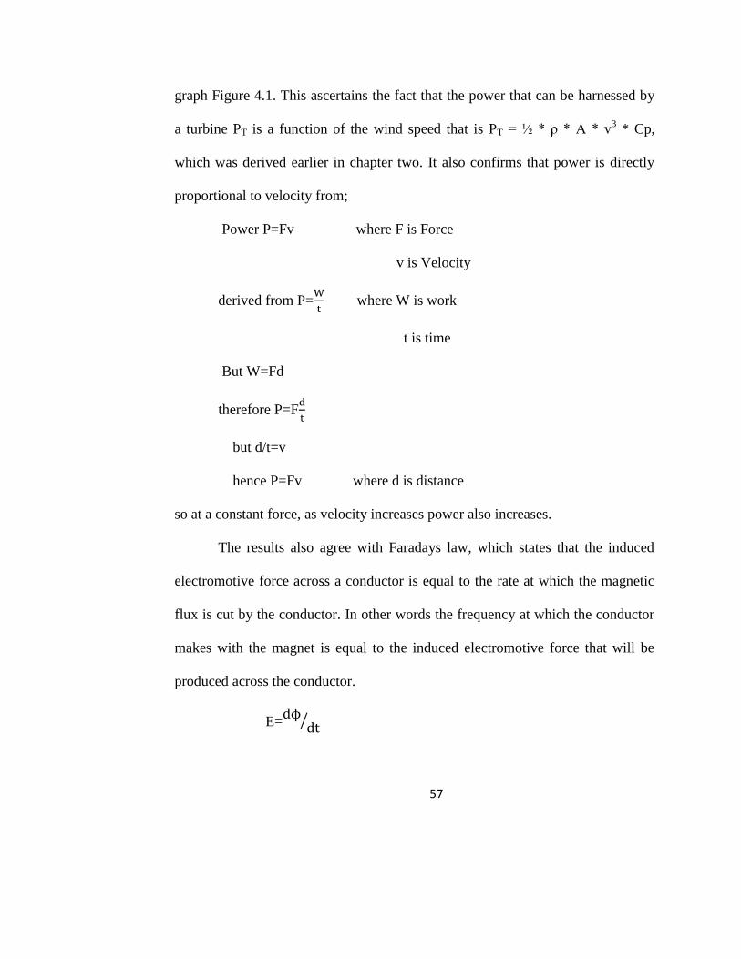
graph Figure 4.1. This ascertains the fact that the power that can be harnessed by
a turbine PT is a function of the wind speed that is PT = ½ * ρ * A * v3 * Cp,
which was derived earlier in chapter two. It also confirms that power is directly
proportional to velocity from;
Power P=Fv where F is Force
v is Velocity
derived from P=
where W is work
t is time
But W=Fd
therefore P=F
but d/t=v
hence P=Fv where d is distance
so at a constant force, as velocity increases power also increases.
The results also agree with Faradays law, which states that the induced
electromotive force across a conductor is equal to the rate at which the magnetic
flux is cut by the conductor. In other words the frequency at which the conductor
makes with the magnet is equal to the induced electromotive force that will be
produced across the conductor.
E=
⁄
58
The bicycle dynamo effect is also supported here since the faster the
bicycle moves or travels the brighter the bulb/lamp shines which is similar to the
above case.
For the second part, it can be seen that from the table 4.2 and figure 4.2
thus the graph, the more close the magnet to the coil, (in other words the smaller
the distance) the higher the voltage thus the induced emf increases inversely as
the distance of separation between the magnet and the loop decreases;
Vα
so the smaller the distance of separation of the coil and the magnet, the
higher the voltage. The graph depicts an inverse graph with an R2 value of 0.916
which is good since it is around 1.0. This agrees with Ampere‘s rule for the
magnetic field, B at a point from a source field.
In the third part comparison was made between the power generated using
two coil set and one coil set. A coil set for this project contains four wire
loops/coils each of about 120 turns and a diameter of about 5cm. The comparison
showed that the two coil set produced greater power than the one coil set which
confirms to Lenz law which can be explained as the number of coil turns being
directly proportional to the induced electromotive force. However the difference
between the two individual power generated was not big enough this shows that
the two coil set is not so efficient. This agrees with the fact that for higher emf
there must be a greater magnetic field strength/magnetic flux density. Thus in
59
order to generate double or higher electromotive force hence greater power, the
concentration must be on providing more or stronger magnetic field/flux on the
conductor and not more conductor on a lesser magnetic flux. In order to generate
higher emf hence greater power, two magnetic sets one below, one on top with the
conductor with higher number of turns in-between the two magnet sets should
rather be used instead of two coil set to one magnetic set.
Finally, the lower readings recorded for the prototype wind turbine may be
due to low efficient construction and design. Another factor may come from the
irregular alignment of the magnets as a result of irregularities and unstable nature
of the wooden disc into which the magnets were stacked into thereby creating
longer and shorter coil and magnet spacing irregularly as it rotates. The less wire
turns/windings and lesser magnets used was also a key factor. The higher gauge
wire used was also noted as another agent. Also the fan was not able to blow a
much higher wind speed to create higher readings that will lead to greater power
generation. Lastly the long cord lengths used for the recording of values may also
be a factor.
60
CHAPTER FIVE
SUMMARY, CONCLUSIONS AND RECOMMENDATIONS
Overview
This chapter deals with the summary of the work and a general conclusion
based on the results gathered. There is also recommendation for further studies on
this project.
Summary
Generating electricity from sustainable energy resource using a
prototype wind turbine was studied. In this study, a pico-wind turbine was
designed and constructed to generate electricity from the wind energy. The
framework behind the generation of electricity was based mainly on the power in
the wind and how to harness it to electrical energy, the concept of Faraday‘s law
of electromagnetic induction and the principle in the design of Savonius VAWT.
Studies such as variation of power with wind speed, variation of induced
electromotive force, emf with distance from coil to magnet and Comparison of
power generated with two coil set to one coil set were done to determine the
parameters of Faradays law which can affect the magnitude of the power
generated.
61
Conclusion
A prototype wind turbine was designed and constructed at the end
of the project with simple, common and cheap materials around and it was able to
record higher values of about 200 mA and 0.20 V thus 0.04 W of power on a
normal afternoon at the third floor of the science building.
It was also realized at the end that wind speed greatly affects the voltages
and hence the power the turbine generates. So in order to produce greater power
output the turbine must be situated at high wind speed areas, which satisfies
Faradays law.
Observation was also made that the smaller the distance of
separation between the magnets and the coils, the better the induction hence
higher voltage and power which agrees with Ampere‘s rule for the magnetic field,
B at a point from a source field. Therefore to obtain optimum power output the
spacing between the magnet and the coil should be kept as small as possible.
The two coil set was found to be more efficient than the one coil set which
verifies the Lenz law. However to create more efficiency more magnets thus more
magnetic flux/field (two magnets set) must be incorporated to a coil set with more
turns/windings.
62
Recommendation
The following recommendations are offered for future work on the study:
1. Further study should be conducted on the prototype to improve the
efficiency of the turbine. Such as wider blades, lesser blades and less
friction.
2. A ferromagnetic material of very high relative permeability design with
little eddy current/effect should be used as the laminations/core material
for the wire loop instead of the air gap and also the space between the
magnet and wire loop should be reduced to increase the power output of
the turbine.
3. The gauge number of the winding wire used for the coil/loop should be
smaller than the 19 AWG used in this work in order to enhance the power
generated. Also more wire windings and magnets should be considered for
optimum power generation.
4. The use of gears or gear box should be incorporated into the design to
enhance its productivity.
5. The following circuit systems, such as a rectifying diode, rechargeable
battery and other available ones should be added to the design for the
storage and effective use of the energy generated.
63
REFERENCES
A Literature Review on Wind Turbines in Ontario June 10, 2011
Andersen, D. 2007. Review of Historical and Modern Utilization of Wind Power.
Denmark: Risø.
Boston University. Wind Turbine, 2009
CliffNotes. (2013). Electromagnetic Induction. Retrieve from
http://m_cliffnotes.com/studyguide/topicArticleid-10453.html
Colby. David W, M.D. et al. December 2009. Wind Turbine Sound and Health
Effects An Expert Panel Review. Prepared for CanWEA and AWEA
Conference Board of Canada. Offshore Wind Energy Leads to Job Creation and
Economic Benefits for Ontario.
Essandoh, E. (2012, September 26). Prospect of Wind Energy in Ghana.
[PowerPoint slides]. (Thesis defence, Kwame Nkrumah University of
Science and Technology: Energy Centre (TEC), Kumasi).
European Wind Energy Association. 2008. Wind at Work: Energy and Job
Creation in the EU. Brussels: European Wind Energy Association.
European Wind Energy Association. [No date]. Wind Power Economics. Brussels:
European Wind Energy Association.
Ghana has 2000-megawatt Wind Power. (2005, April 28). Ghana News,
GNA. (Article 80360). Retrieve from Ghana Web Portal.
64
Global Wind Energy Council. 2010. Global Wind Report Annual Market Update
2010. Brussels: Global Wind Energy Council.
Hanson, M.O.L. (2008). Aerodynamics of Wind Turbines. (2nd ed). London,
Sterling,VA: Earthscan. pp. 1-39. ISBN: 978-1-84407-438-9
Hemani, A. (2012). Wind Turbine Technology. New York: Cengage learning.
pp. 4-61. ISBN-13: 978-1-4354-8646-1
Ingram, G. (2011). Wind Turbine Blade Analysis using the Blade Element
Momentum Method version 1.1. UK: Author. pp. 7-11. Retrieve from
http://creativecommons.org/licenses/by-sa/3.0/.
Jamaica Sustainability Development Network. (2012). World summit on
Sustainable Development. Kingston, Jamaica: Ministry of Land and
Environment.
Jefferson, W.T., and Micheal, J.D. (2008). Sustainable energy: choosing
among options. Journal of Industral Ecology. 12(2), 248-249.
Doi: 10.1111/i 15309290200819
Kalmikov A. and Dykes K. (2011) Wind Power Fundamentals
King, Dr. Arlene, Chief Medical Officer. May 2010. The Potential Health Impact
of Wind Turbines. Toronto : Queens Printer for Ontario,
Kolachara, S. (2012). A Computational Framework for the Design and
Analysis of Savonius Wind Turbine. (Unpublished Thesis, Indian
65
Institute of Technology Madras: Department of Engineering Design).
pp. 3-11.
Kraus, J.D. (1992). Electromagnetic. (4th ed). New York: McGraw-Hill.
p. 236. ISBN: 0-07-035621-1.
Menet, J.L. (2004). A Double Step Savonius Rotor for the Local Generation of
Electricity: a Design Study. Renewable Energy 29(2009),
pp. 1843-1862.
National Renewable Energy Centre. (2009). CENER Wind Energy: The Fact-
a guide to the Technology, Economics and future of Wind Power.
European Wind Energy Association. ISBN: 978-84407-710-6.
National Renewable Energy Laboratory. (nd). NREL Ghana Wind Energy
Mapping Activity: as part of Solar and Wind Resource Assessment,
SWERA. Report presented to United Nation Environment Programme.
USA.
Serway, R.A., and Reicher, R.J. (2000). Physics: for Scientists and Engineers.
(5th ed). Saunders College, USA. pp. 994-995. Retrieve from
http://www.harcourtcollege.com.
Tiwari, P., Swan, D., and Kumar, K.A. (2010). Study of Wind Energy System
with Induction Generators. (Unpublished thesis, National Institute of
Technology: Department of Electrical Engineering, Roukela).
pp. 26, 28 60
66
Wesis,S.B. (2010). Vertical Axis Wind Turbine with Continuous Blade Angle
Adjustment. (Unpublished Thesis, Massachusetts Institute of Technology).
pp. 7-10.
World Fact Book, 2010.
Wroblewski, D. (2010). Wind Turbine. [PowerPoint slides] Retrieve from
Coherent Application Threads [CAT], Bosten University. p. 1
Retrieve from http://people.bu.edu.
www.windustry.org
Yong, H.D., &, Freeman, R.A., (2008). University Physics. (12th ed).
San Fransico, USA: Pearon Adison Wesley. pp. 973-983
ISBN-13: 978-0-321-50130-1