Wind Monitor Series - Campbell Sci · Affiliate companies handle repairs ... B-1. Wiring for...
36
Wind Monitor Series 05103, 05103-45, 05106, 05108, 05108-45, and 05305 Revision: 7/18 Copyright © 1984 – 2018 Campbell Scientific, Inc.
Transcript of Wind Monitor Series - Campbell Sci · Affiliate companies handle repairs ... B-1. Wiring for...

Wind Monitor Series 05103, 05103-45, 05106,
05108, 05108-45, and 05305
Revision: 7/18 Copyright © 1984 – 2018 Campbell Scientific, Inc.

Limited Warranty “Products manufactured by CSI are warranted by CSI to be free from defects in materials and workmanship under normal use and service for twelve months from the date of shipment unless otherwise specified in the corresponding product manual. (Product manuals are available for review online at www.campbellsci.com.) Products not manufactured by CSI, but that are resold by CSI, are warranted only to the limits extended by the original manufacturer. Batteries, fine-wire thermocouples, desiccant, and other consumables have no warranty. CSI’s obligation under this warranty is limited to repairing or replacing (at CSI’s option) defective Products, which shall be the sole and exclusive remedy under this warranty. The Customer assumes all costs of removing, reinstalling, and shipping defective Products to CSI. CSI will return such Products by surface carrier prepaid within the continental United States of America. To all other locations, CSI will return such Products best way CIP (port of entry) per Incoterms ® 2010. This warranty shall not apply to any Products which have been subjected to modification, misuse, neglect, improper service, accidents of nature, or shipping damage. This warranty is in lieu of all other warranties, expressed or implied. The warranty for installation services performed by CSI such as programming to customer specifications, electrical connections to Products manufactured by CSI, and Product specific training, is part of CSI's product warranty. CSI EXPRESSLY DISCLAIMS AND EXCLUDES ANY IMPLIED WARRANTIES OF MERCHANTABILITY OR FITNESS FOR A PARTICULAR PURPOSE. CSI hereby disclaims, to the fullest extent allowed by applicable law, any and all warranties and conditions with respect to the Products, whether express, implied or statutory, other than those expressly provided herein.”

Assistance Products may not be returned without prior authorization. The following contact information is for US and international customers residing in countries served by Campbell Scientific, Inc. directly. Affiliate companies handle repairs for customers within their territories. Please visit www.campbellsci.com to determine which Campbell Scientific company serves your country.
To obtain a Returned Materials Authorization (RMA) number, contact CAMPBELL SCIENTIFIC, INC., phone (435) 227-9000. Please write the issued RMA number clearly on the outside of the shipping container. Campbell Scientific’s shipping address is:
CAMPBELL SCIENTIFIC, INC. RMA#_____ 815 West 1800 North Logan, Utah 84321-1784
For all returns, the customer must fill out a “Statement of Product Cleanliness and Decontamination” form and comply with the requirements specified in it. The form is available from our website at www.campbellsci.com/repair. A completed form must be either emailed to [email protected] or faxed to (435) 227-9106. Campbell Scientific is unable to process any returns until we receive this form. If the form is not received within three days of product receipt or is incomplete, the product will be returned to the customer at the customer’s expense. Campbell Scientific reserves the right to refuse service on products that were exposed to contaminants that may cause health or safety concerns for our employees.

Safety DANGER — MANY HAZARDS ARE ASSOCIATED WITH INSTALLING, USING, MAINTAINING, AND WORKING ON OR AROUND TRIPODS, TOWERS, AND ANY ATTACHMENTS TO TRIPODS AND TOWERS SUCH AS SENSORS, CROSSARMS, ENCLOSURES, ANTENNAS, ETC. FAILURE TO PROPERLY AND COMPLETELY ASSEMBLE, INSTALL, OPERATE, USE, AND MAINTAIN TRIPODS, TOWERS, AND ATTACHMENTS, AND FAILURE TO HEED WARNINGS, INCREASES THE RISK OF DEATH, ACCIDENT, SERIOUS INJURY, PROPERTY DAMAGE, AND PRODUCT FAILURE. TAKE ALL REASONABLE PRECAUTIONS TO AVOID THESE HAZARDS. CHECK WITH YOUR ORGANIZATION'S SAFETY COORDINATOR (OR POLICY) FOR PROCEDURES AND REQUIRED PROTECTIVE EQUIPMENT PRIOR TO PERFORMING ANY WORK.
Use tripods, towers, and attachments to tripods and towers only for purposes for which they are designed. Do not exceed design limits. Be familiar and comply with all instructions provided in product manuals. Manuals are available at www.campbellsci.com or by telephoning (435) 227-9000 (USA). You are responsible for conformance with governing codes and regulations, including safety regulations, and the integrity and location of structures or land to which towers, tripods, and any attachments are attached. Installation sites should be evaluated and approved by a qualified engineer. If questions or concerns arise regarding installation, use, or maintenance of tripods, towers, attachments, or electrical connections, consult with a licensed and qualified engineer or electrician.
General • Prior to performing site or installation work, obtain required approvals and permits. Comply
with all governing structure-height regulations, such as those of the FAA in the USA. • Use only qualified personnel for installation, use, and maintenance of tripods and towers, and
any attachments to tripods and towers. The use of licensed and qualified contractors is highly recommended.
• Read all applicable instructions carefully and understand procedures thoroughly before beginning work.
• Wear a hardhat and eye protection, and take other appropriate safety precautions while working on or around tripods and towers.
• Do not climb tripods or towers at any time, and prohibit climbing by other persons. Take reasonable precautions to secure tripod and tower sites from trespassers.
• Use only manufacturer recommended parts, materials, and tools.
Utility and Electrical • You can be killed or sustain serious bodily injury if the tripod, tower, or attachments you are
installing, constructing, using, or maintaining, or a tool, stake, or anchor, come in contact with overhead or underground utility lines.
• Maintain a distance of at least one-and-one-half times structure height, 20 feet, or the distance required by applicable law, whichever is greater, between overhead utility lines and the structure (tripod, tower, attachments, or tools).
• Prior to performing site or installation work, inform all utility companies and have all underground utilities marked.
• Comply with all electrical codes. Electrical equipment and related grounding devices should be installed by a licensed and qualified electrician.
Elevated Work and Weather • Exercise extreme caution when performing elevated work. • Use appropriate equipment and safety practices. • During installation and maintenance, keep tower and tripod sites clear of un-trained or non-
essential personnel. Take precautions to prevent elevated tools and objects from dropping. • Do not perform any work in inclement weather, including wind, rain, snow, lightning, etc.
Maintenance • Periodically (at least yearly) check for wear and damage, including corrosion, stress cracks,
frayed cables, loose cable clamps, cable tightness, etc. and take necessary corrective actions. • Periodically (at least yearly) check electrical ground connections.
WHILE EVERY ATTEMPT IS MADE TO EMBODY THE HIGHEST DEGREE OF SAFETY IN ALL CAMPBELL SCIENTIFIC PRODUCTS, THE CUSTOMER ASSUMES ALL RISK FROM ANY INJURY RESULTING FROM IMPROPER INSTALLATION, USE, OR MAINTENANCE OF TRIPODS, TOWERS, OR ATTACHMENTS TO TRIPODS AND TOWERS SUCH AS SENSORS, CROSSARMS, ENCLOSURES, ANTENNAS, ETC.

i
Table of Contents PDF viewers: These page numbers refer to the printed version of this document. Use the PDF reader bookmarks tab for links to specific sections.
1. Introduction ................................................................ 1
2. Precautions ................................................................ 1
3. Initial Inspection ......................................................... 2
3.1 Ships With ............................................................................................ 2
4. QuickStart ................................................................... 2
5. Overview ..................................................................... 4
6. Specifications ............................................................. 5
7. Installation .................................................................. 7
7.1 Siting .................................................................................................... 7 7.2 Assembly and Mounting ...................................................................... 7
7.2.1 Mounting the Wind Monitor to a Crossarm .................................. 7 7.2.2 Mounting the Wind Monitor Atop a Tripod Mast......................... 9
7.3 Wiring ................................................................................................ 10 7.4 Programming ...................................................................................... 10
7.4.1 Wind Speed ................................................................................. 11 7.4.2 Wind Direction ........................................................................... 11 7.4.3 Wind Vector Processing Instruction ........................................... 12
8. Sensor Maintenance ................................................ 12
9. Troubleshooting ....................................................... 13
9.1 Wind Direction ................................................................................... 13 9.2 Wind Speed ........................................................................................ 13
10. References ................................................................ 14
Appendices
A. Importing Short Cut Code Into CRBasic Editor ... A-1
B. Example Programs ................................................. B-1
B.1 CR1000X Example Program............................................................ B-1 B.2 CR6 Example Program .................................................................... B-2 B.3 CR200(X) Example Program ........................................................... B-3
Table of Contents
ii
C. Wind Direction Sensor Orientation ....................... C-1
C.1 Determining True North and Sensor Orientation ............................ C-1
D. Wind Direction Measurement Theory ................... D-1
Figures 7-1. CM220 Right Angle Mounting Kit mounted to a crossarm ................ 8 7-2. Wind monitor mounted to a crossarm by using 1- x 1-in. Nu-Rail
Crossover Fitting .............................................................................. 9 7-3. The CM216 allows the wind monitor to mount atop a tripod mast ..... 9 C-1. Magnetic declination for the contiguous United States (2015) ....... C-2 C-2. Declination angles east of true north are subtracted from 0 to
get true north ................................................................................ C-2 C-3. Declination angles west of true north are added to 0 to get true
north ............................................................................................. C-3 D-1. 05103 potentiometer in a half bridge circuit ................................... D-1
Tables 1-1. R.M. Young Wind Monitors Models .................................................. 1 5-1. Recommended Cable Lengths ............................................................. 4 6-1. Wind Speed Specifications .................................................................. 5 6-2. Wind Direction Specifications ............................................................ 6 6-3. Physical Specifications ........................................................................ 6 7-1. Wire Color, Wire Function, and Datalogger Connection ................. 10 7-2. Wind Speed Multiplier ...................................................................... 11 7-3. Parameters for Wind Direction .......................................................... 12 B-1. Wiring for Example Programs ......................................................... B-1
CRBasic Examples B-1. CR1000X Example Program ........................................................... B-1 B-2. CR6 Example Program .................................................................... B-2 B-3. CR200(X) Example Program .......................................................... B-3
1
Wind Monitor Series 1. Introduction
Wind monitors measure horizontal wind speed and direction. The different models are designed for different applications (TABLE 1-1). The wind monitors are manufactured by R.M. Young.
TABLE 1-1. R.M. Young Wind Monitors Models
Model Description
05103 Standard wind monitor
05103-45 Alpine wind monitor (discourages ice buildup)
05106 Marine wind monitor
05108 Heavy-duty wind monitor that greatly extends service life
05108-45 Heavy-duty wind monitor for alpine applications
05305 High-performance wind monitor for air quality applications
This manual provides information only for CRBasic dataloggers. It is also compatible with most of our retired Edlog dataloggers. For Edlog datalogger support, see an older manual at www.campbellsci.com/old-manuals.
2. Precautions • READ AND UNDERSTAND the Safety section at the front of this
manual.
• The wind monitor is a precision instrument. Please handle it with care.
• Do not use cable lengths greater than 30 m (9 ft) in electrically noisy environments.
• The black outer jacket of the cable is Santoprene® rubber. This compound was chosen for its resistance to temperature extremes, moisture, and ultraviolet (UV) degradation. However, this jacket will support combustion in air. It is rated as slow burning when tested according to U.L. 94 H.B. and will pass FMVSS302. Local fire codes may preclude its use inside buildings.
• Wire color and functions of sensors purchased through Campbell Scientific may not correspond with the wire colors and functions given in the manufacturer’s manual. To ensure proper function, follow the wiring provided in Short Cut or in the Campbell Scientific manual.
• Wind monitors purchased directly from R.M. Young may not have the 1 MΩ resistor used to short the readings in the dead band to ground.
NOTE
Wind Monitor Series
2
3. Initial Inspection • Upon receipt of the wind monitor, inspect the packaging and contents for
damage. File damage claims with the shipping company. Immediately check package contents against the shipping documentation (see Section 3.1, Ships With (p. 2)). Contact Campbell Scientific about any discrepancies.
• The model number and cable length are printed on a label at the connection end of the cable. Check this information against the shipping documents to ensure the expected product and cable length are received.
3.1 Ships With The wind monitors ship with:
(1) Allen wrench from manufacturer (1) Bearing spacer from manufacturer (1) Calibration sheet (1) Unthreaded aluminum pipe, 1-inch IPS, 12-inch length
4. QuickStart A video that describes datalogger programming using Short Cut is available at: www.campbellsci.com/videos/cr1000x-datalogger-getting-started-program-part-3. Short Cut is an easy way to program your datalogger to measure this sensor and assign datalogger wiring terminals. Short Cut is available as a download on www.campbellsci.com. It is included in installations of LoggerNet, PC200W, PC400, or RTDAQ.
The following procedure also describes programming with Short Cut.
1. Open Short Cut and create a new program.
2. Double-click the datalogger model.
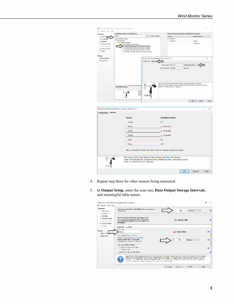
3. In the Available Sensors and Devices box, type 05103, 05106, or 05305-AQ or locate the sensor in the Sensors | Meteorological | Wind Speed & Direction folder. Double-click 05103 Wind Speed & Direction Sensor, 05106 Wind Speed & Direction Sensor, or 05305-AQ Wind Speed & Direction Sensor. The wind speed defaults to meters/second. This can be changed by clicking the Wind Speed box and selecting one of the other options. Click the Wiring tab to see how the sensor is to be wired to the datalogger.
Wind Monitor Series
3
4. Repeat step three for other sensors being measured.
5. In Output Setup, enter the scan rate, Data Output Storage Intervals, and meaningful table names.
Wind Monitor Series
4
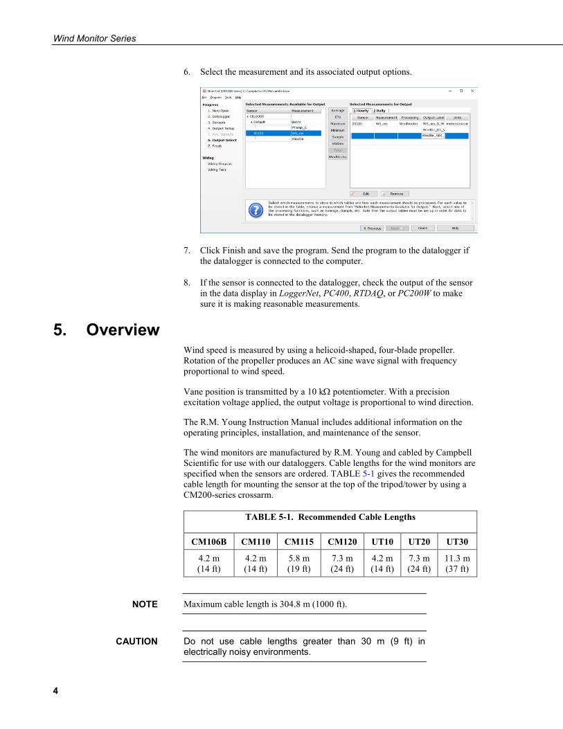
6. Select the measurement and its associated output options.
7. Click Finish and save the program. Send the program to the datalogger if the datalogger is connected to the computer.
8. If the sensor is connected to the datalogger, check the output of the sensor in the data display in LoggerNet, PC400, RTDAQ, or PC200W to make sure it is making reasonable measurements.
5. Overview Wind speed is measured by using a helicoid-shaped, four-blade propeller. Rotation of the propeller produces an AC sine wave signal with frequency proportional to wind speed.
Vane position is transmitted by a 10 kΩ potentiometer. With a precision excitation voltage applied, the output voltage is proportional to wind direction.
The R.M. Young Instruction Manual includes additional information on the operating principles, installation, and maintenance of the sensor.
The wind monitors are manufactured by R.M. Young and cabled by Campbell Scientific for use with our dataloggers. Cable lengths for the wind monitors are specified when the sensors are ordered. TABLE 5-1 gives the recommended cable length for mounting the sensor at the top of the tripod/tower by using a CM200-series crossarm.
TABLE 5-1. Recommended Cable Lengths
CM106B CM110 CM115 CM120 UT10 UT20 UT30
4.2 m (14 ft)
4.2 m (14 ft)
5.8 m (19 ft)
7.3 m (24 ft)
4.2 m (14 ft)
7.3 m (24 ft)
11.3 m (37 ft)
Maximum cable length is 304.8 m (1000 ft).
Do not use cable lengths greater than 30 m (9 ft) in electrically noisy environments.
NOTE
CAUTION
Wind Monitor Series
5
6. Specifications TABLE 6-1, TABLE 6-2, and TABLE 6-3 provide the wind speed, wind direction, and physical specifications, respectively.
Features: • Rugged enough for harsh environments • Constructed with thermoplastic material that resists corrosion from
sea-air environments and atmospheric pollutants • Ideal for wind profile studies • Compatible with the LLAC4 4-channel Low Level AC Conversion
Module, which increases the number of anemometers one datalogger can measure
• Compatible with Campbell Scientific CRBasic dataloggers: CR200(X) series, CR300 series, CR6 series, CR800 series, CR1000X, CR1000, CR3000, CR5000, and CR9000(X)
TABLE 6-1. Wind Speed Specifications
05103 Wind
Monitor
05103-45 Wind
Monitor-Alpine
05106 Wind
Monitor-MA
05108 Heavy Duty Wind
Monitor
05108-45 Heavy Duty
Wind Monitor-
Alpine 05305
Wind Monitor-AQ
Range 0 to 100 m s–1 (0 to 224 mph) 0 to 50 m s–1 (0 to 112 mph)
Accuracy ±0.3 m s–1 (±0.6 mph) or 1% of reading ±0.2 m s–1
(±0.4 mph) or 1% of reading
Starting Threshold 1.0 m s–1 (2.2 mph) 2.4 mph
(1.1 m s–1) 1.0 m s–1 (2.2 mph) 0.4 m s–1 (0.9 mph)
Distance Constant
(63% recovery)
2.7 m (8.9 ft) 2.1 m (6.9 ft)
Output ac voltage (3 pulses per revolution); 1800 rpm (90 Hz) = 8.8 m s–1 (19.7 mph)
ac voltage (3 pulses per revolution);
1800 rpm (90 Hz) = 9.2 m s–1 (20.6 mph)
Resolution (0.0980 m s–1)/(scan rate in seconds) or (0.2192 mph)/(scan rate in (seconds)
(0.1024 m s–1)/ (scan rate in sec.) or (0.2290 mph)/(scan
rate in sec.)
Wind Monitor Series
6
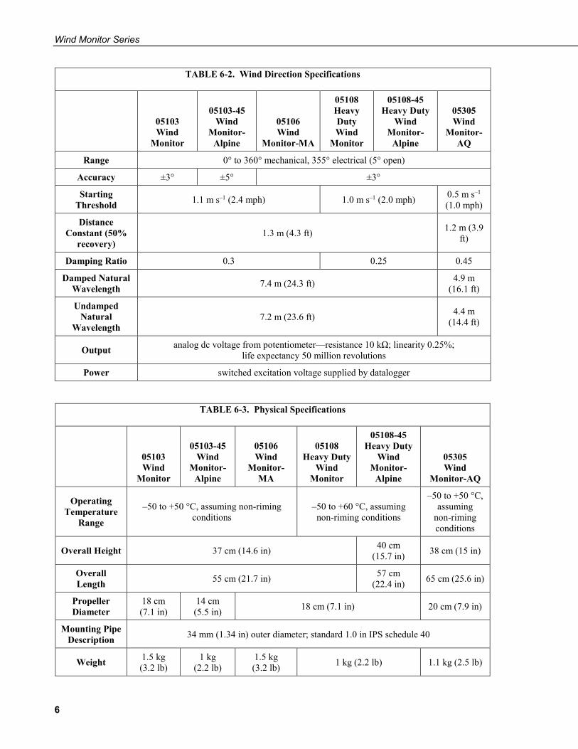
TABLE 6-2. Wind Direction Specifications
05103 Wind
Monitor
05103-45 Wind
Monitor-Alpine
05106 Wind
Monitor-MA
05108 Heavy Duty Wind
Monitor
05108-45 Heavy Duty
Wind Monitor-
Alpine
05305 Wind
Monitor-AQ
Range 0° to 360° mechanical, 355° electrical (5° open)
Accuracy ±3° ±5° ±3°
Starting Threshold 1.1 m s–1 (2.4 mph) 1.0 m s–1 (2.0 mph) 0.5 m s–1
(1.0 mph)
Distance Constant (50%
recovery) 1.3 m (4.3 ft) 1.2 m (3.9
ft)
Damping Ratio 0.3 0.25 0.45
Damped Natural Wavelength 7.4 m (24.3 ft) 4.9 m
(16.1 ft)
Undamped Natural
Wavelength 7.2 m (23.6 ft) 4.4 m
(14.4 ft)
Output analog dc voltage from potentiometer—resistance 10 kΩ; linearity 0.25%; life expectancy 50 million revolutions
Power switched excitation voltage supplied by datalogger
TABLE 6-3. Physical Specifications
05103 Wind
Monitor
05103-45 Wind
Monitor-Alpine
05106 Wind
Monitor-MA
05108
Heavy Duty Wind
Monitor
05108-45 Heavy Duty
Wind Monitor-
Alpine
05305 Wind
Monitor-AQ
Operating Temperature
Range
–50 to +50 °C, assuming non-riming conditions
–50 to +60 °C, assuming non-riming conditions
–50 to +50 °C, assuming
non-riming conditions
Overall Height 37 cm (14.6 in) 40 cm (15.7 in) 38 cm (15 in)
Overall Length 55 cm (21.7 in) 57 cm
(22.4 in) 65 cm (25.6 in)
Propeller Diameter
18 cm (7.1 in)
14 cm (5.5 in) 18 cm (7.1 in) 20 cm (7.9 in)
Mounting Pipe Description 34 mm (1.34 in) outer diameter; standard 1.0 in IPS schedule 40
Weight 1.5 kg (3.2 lb)
1 kg (2.2 lb)
1.5 kg (3.2 lb) 1 kg (2.2 lb) 1.1 kg (2.5 lb)
Wind Monitor Series
7
7. Installation If you are programming your datalogger by using Short Cut, skip Section 7.3, Wiring (p. 10), and Section 7.4, Programming (p. 10). Short Cut does this work for you. See Section 4, QuickStart (p. 2), for a Short Cut tutorial.
7.1 Siting Locate wind sensors away from obstructions such as trees or buildings. Generally, there should be a horizontal distance of at least ten times the height of the obstruction between the wind monitor and the obstruction. If the sensors need to be mounted on a roof, the height of the sensors above the roof, should be at least 1.5 times the height of the building. See Section 10, References (p. 14), for a list of references that discuss siting wind speed and direction sensors.
7.2 Assembly and Mounting Tools required:
• 5/64 inch Allen wrench • 1/2 inch open end wrench • Compass and declination angle for the site (see Appendix C, Wind
Direction Sensor Orientation (p. C-1)) • Small screw driver provided with datalogger • UV resistant cable ties • 6 to 10 inch torpedo level
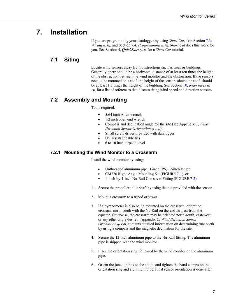
7.2.1 Mounting the Wind Monitor to a Crossarm Install the wind monitor by using:
• Unthreaded aluminum pipe, 1-inch IPS, 12-inch length • CM220 Right-Angle Mounting Kit (FIGURE 7-1), or • 1-inch-by-1-inch Nu-Rail Crossover Fitting (FIGURE 7-2)
1. Secure the propeller to its shaft by using the nut provided with the sensor.
2. Mount a crossarm to a tripod or tower.
3. If a pyranometer is also being mounted on the crossarm, orient the crossarm north-south with the Nu-Rail on the end farthest from the equator. Otherwise, the crossarm may be oriented north-south, east-west, or any other angle desired. Appendix C, Wind Direction Sensor Orientation (p. C-1), contains detailed information on determining true north by using a compass and the magnetic declination for the site.
4. Secure the 12-inch aluminum pipe to the Nu-Rail fitting. The aluminum pipe is shipped with the wind monitor.
5. Place the orientation ring, followed by the wind monitor on the aluminum pipe.
6. Orient the junction box to the south, and tighten the band clamps on the orientation ring and aluminum pipe. Final sensor orientation is done after
Wind Monitor Series
8
the datalogger has been programmed to measure wind direction as described in Appendix C, Wind Direction Sensor Orientation (p. C-1).
7. Use the torpedo level to ensure that the wind monitor is level.
8. Route the sensor cable along the underside of the crossarm to the tripod or tower, and to the instrument enclosure.
9. Secure the cable to the crossarm and tripod or tower by using cable ties.
FIGURE 7-1. CM220 Right Angle Mounting Kit mounted to a crossarm
CM220
Crossarm
Wind Monitor Series
9
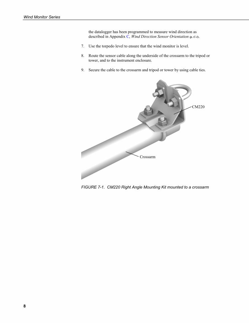
FIGURE 7-2. Wind monitor mounted to a crossarm by using 1- x 1-in. Nu-Rail Crossover Fitting
7.2.2 Mounting the Wind Monitor Atop a Tripod Mast The wind monitor mounts on top of a CM106B, CM110, CM115, or CM120 tripod by using the CM216 (see FIGURE 7-3). The CM216 extends 10 cm (4 in) above the mast of the tripod.
FIGURE 7-3. The CM216 allows the wind monitor to mount atop a tripod mast
Wind Monitor
1- x 1-in. Nu-Rail Crossover Fitting
Mounting Pipe (supplied with sensor)
CM200 Series Crossarm
Wind Monitor Series
10
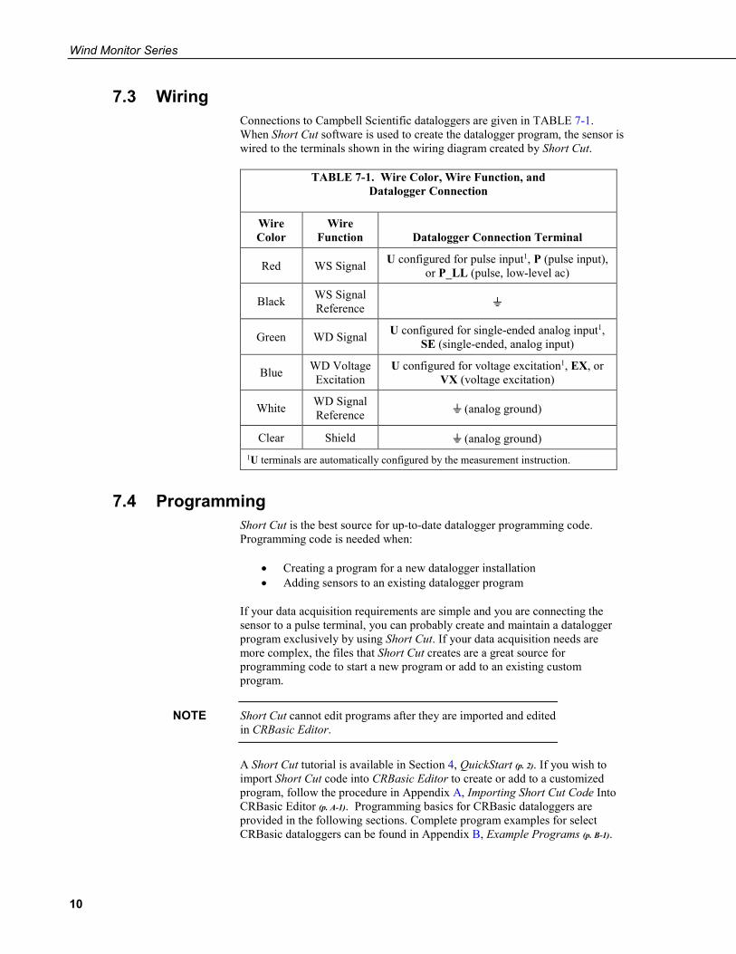
7.3 Wiring Connections to Campbell Scientific dataloggers are given in TABLE 7-1. When Short Cut software is used to create the datalogger program, the sensor is wired to the terminals shown in the wiring diagram created by Short Cut.
TABLE 7-1. Wire Color, Wire Function, and Datalogger Connection
Wire Color
Wire Function Datalogger Connection Terminal
Red WS Signal U configured for pulse input1, P (pulse input), or P_LL (pulse, low-level ac)
Black WS Signal Reference
Green WD Signal U configured for single-ended analog input1, SE (single-ended, analog input)
Blue WD Voltage Excitation
U configured for voltage excitation1, EX, or VX (voltage excitation)
White WD Signal Reference (analog ground)
Clear Shield (analog ground) 1U terminals are automatically configured by the measurement instruction.
7.4 Programming Short Cut is the best source for up-to-date datalogger programming code. Programming code is needed when:
• Creating a program for a new datalogger installation • Adding sensors to an existing datalogger program
If your data acquisition requirements are simple and you are connecting the sensor to a pulse terminal, you can probably create and maintain a datalogger program exclusively by using Short Cut. If your data acquisition needs are more complex, the files that Short Cut creates are a great source for programming code to start a new program or add to an existing custom program.
Short Cut cannot edit programs after they are imported and edited in CRBasic Editor.
A Short Cut tutorial is available in Section 4, QuickStart (p. 2). If you wish to import Short Cut code into CRBasic Editor to create or add to a customized program, follow the procedure in Appendix A, Importing Short Cut Code Into CRBasic Editor (p. A-1). Programming basics for CRBasic dataloggers are provided in the following sections. Complete program examples for select CRBasic dataloggers can be found in Appendix B, Example Programs (p. B-1).
NOTE
Wind Monitor Series
11
Programming basics and programming examples for Edlog dataloggers are provided at www.campbellsci.com\old-manuals.
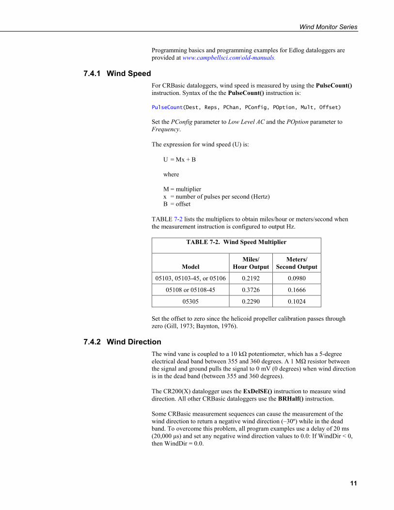
7.4.1 Wind Speed For CRBasic dataloggers, wind speed is measured by using the PulseCount() instruction. Syntax of the the PulseCount() instruction is:
PulseCount(Dest, Reps, PChan, PConfig, POption, Mult, Offset)
Set the PConfig parameter to Low Level AC and the POption parameter to Frequency.
The expression for wind speed (U) is:
U = Mx + B where M = multiplier x = number of pulses per second (Hertz) B = offset
TABLE 7-2 lists the multipliers to obtain miles/hour or meters/second when the measurement instruction is configured to output Hz.
TABLE 7-2. Wind Speed Multiplier
Model
Miles/ Hour Output
Meters/ Second Output
05103, 05103-45, or 05106 0.2192 0.0980
05108 or 05108-45 0.3726 0.1666
05305 0.2290 0.1024 Set the offset to zero since the helicoid propeller calibration passes through zero (Gill, 1973; Baynton, 1976).
7.4.2 Wind Direction The wind vane is coupled to a 10 kΩ potentiometer, which has a 5-degree electrical dead band between 355 and 360 degrees. A 1 MΩ resistor between the signal and ground pulls the signal to 0 mV (0 degrees) when wind direction is in the dead band (between 355 and 360 degrees).
The CR200(X) datalogger uses the ExDelSE() instruction to measure wind direction. All other CRBasic dataloggers use the BRHalf() instruction.
Some CRBasic measurement sequences can cause the measurement of the wind direction to return a negative wind direction (–30º) while in the dead band. To overcome this problem, all program examples use a delay of 20 ms (20,000 μs) and set any negative wind direction values to 0.0: If WindDir < 0, then WindDir = 0.0.
Wind Monitor Series
12
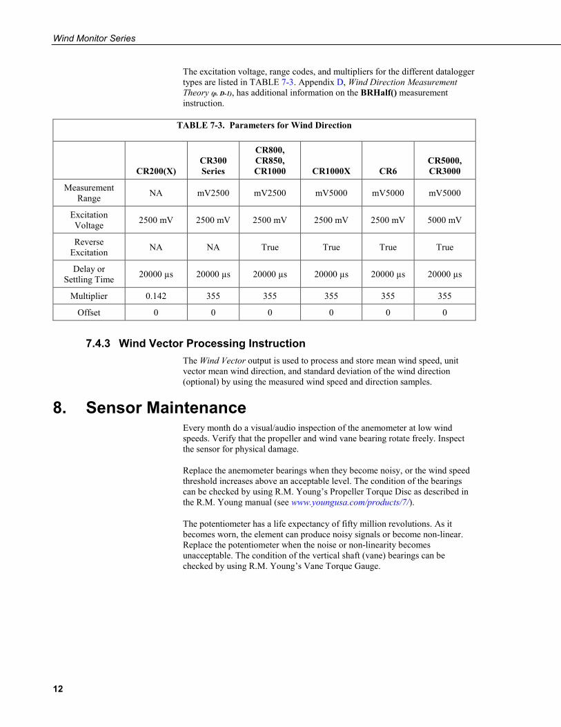
The excitation voltage, range codes, and multipliers for the different datalogger types are listed in TABLE 7-3. Appendix D, Wind Direction Measurement Theory (p. D-1), has additional information on the BRHalf() measurement instruction.
TABLE 7-3. Parameters for Wind Direction
CR200(X) CR300 Series
CR800, CR850, CR1000 CR1000X CR6
CR5000, CR3000
Measurement Range NA mV2500 mV2500 mV5000 mV5000 mV5000
Excitation Voltage 2500 mV 2500 mV 2500 mV 2500 mV 2500 mV 5000 mV
Reverse Excitation NA NA True True True True
Delay or Settling Time 20000 µs 20000 µs 20000 µs 20000 µs 20000 µs 20000 µs
Multiplier 0.142 355 355 355 355 355
Offset 0 0 0 0 0 0
7.4.3 Wind Vector Processing Instruction The Wind Vector output is used to process and store mean wind speed, unit vector mean wind direction, and standard deviation of the wind direction (optional) by using the measured wind speed and direction samples.
8. Sensor Maintenance Every month do a visual/audio inspection of the anemometer at low wind speeds. Verify that the propeller and wind vane bearing rotate freely. Inspect the sensor for physical damage.
Replace the anemometer bearings when they become noisy, or the wind speed threshold increases above an acceptable level. The condition of the bearings can be checked by using R.M. Young’s Propeller Torque Disc as described in the R.M. Young manual (see www.youngusa.com/products/7/).
The potentiometer has a life expectancy of fifty million revolutions. As it becomes worn, the element can produce noisy signals or become non-linear. Replace the potentiometer when the noise or non-linearity becomes unacceptable. The condition of the vertical shaft (vane) bearings can be checked by using R.M. Young’s Vane Torque Gauge.
Wind Monitor Series
13
Campbell Scientific recommends factory replacement of the bearings and potentiometer. Refer to the Assistance page of this document for the procedure of acquiring a Returned Materials Authorization (RMA). Mechanically-adept users may choose to replace the bearings or potentiometer themselves. Instructions for replacing the bearings and potentiometer are given in R.M. Young’s manuals (www.youngusa.com/products/7/).
9. Troubleshooting 9.1 Wind Direction
Symptom: NAN, –9999, or no change in direction
1. Check that the sensor is wired to the excitation and single-ended terminal specified by the measurement instruction.
2. Verify that the excitation voltage and range code are correct for the datalogger type.
3. Disconnect the sensor from the datalogger and use an ohmmeter to check the potentiometer. Resistance should be about 10 kΩ between the blue and white wires. The resistance between either the blue/green or white/green wires should vary between about 1 kΩ to 11 kΩ depending on vane position. Resistance when the vane is in the 5 degree dead band should be about 1 MΩ.
Symptom: Incorrect wind direction
1. Verify that the excitation voltage, range code, multiplier and offset parameters are correct for the datalogger type.
2. Check orientation of sensor as described in Section 7, Installation (p. 7).
9.2 Wind Speed Symptom: No wind speed
1. Check that the sensor is wired to the pulse terminal specified by the pulse count instruction.
2. Disconnect the sensor from the datalogger and use an ohmmeter to check the coil. The resistance between the red and black wires should be about 2075 Ω. Infinite resistance indicates an open coil; low resistance indicates a shorted coil.
3. Verify that the configuration code, and multiplier and offset parameters for the pulse count instruction are correct for the datalogger type.
NOTE

Wind Monitor Series
14
10. References Gill, G.C., 1973: The Helicoid Anemometer Atmosphere, II, 145–155.
Baynton, H.W., 1976: Errors in Wind Run Estimates from Rotational Anemometers, Bul. Am. Met. Soc., vol. 57, No. 9, 1127–1130.
The following references give detailed information on siting wind speed and wind direction sensors.
EPA, 1989: Quality Assurance Handbook for Air Pollution Measurements System, Office of Research and Development, Research Triangle Park, NC, 27711.
EPA, 1987: On-Site Meteorological Program Guidance for Regulatory Modeling Applications, EPA-450/4-87-013, Office of Air Quality Planning and Standards, Research Triangle Park, NC 27711.
The State Climatologist, 1985: Publication of the American Association of State Climatologists: Height and Exposure Standards, for Sensors on Automated Weather Stations, vol. 9, No. 4.
WMO, 1983: Guide to Meteorological Instruments and Methods of Observation, World Meteorological Organization, No. 8, 5th edition, Geneva, Switzerland.
A-1
Appendix A. Importing Short Cut Code Into CRBasic Editor
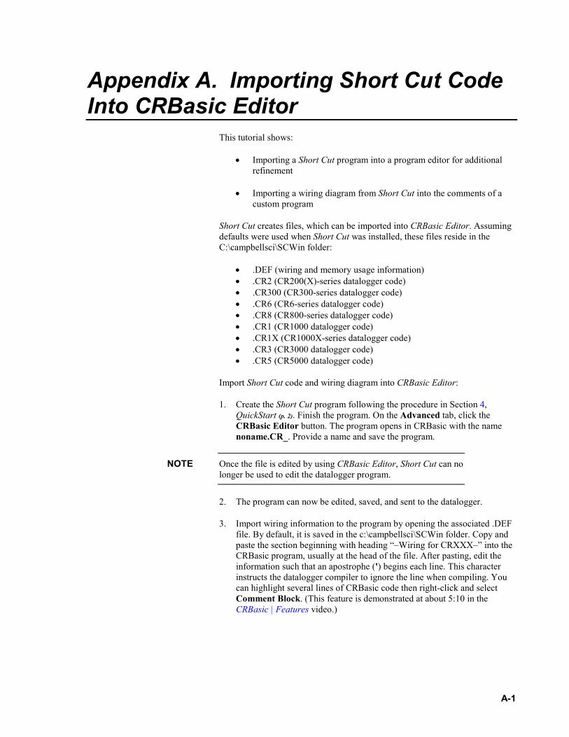
This tutorial shows:
• Importing a Short Cut program into a program editor for additional refinement
• Importing a wiring diagram from Short Cut into the comments of a custom program
Short Cut creates files, which can be imported into CRBasic Editor. Assuming defaults were used when Short Cut was installed, these files reside in the C:\campbellsci\SCWin folder:
• .DEF (wiring and memory usage information) • .CR2 (CR200(X)-series datalogger code) • .CR300 (CR300-series datalogger code) • .CR6 (CR6-series datalogger code) • .CR8 (CR800-series datalogger code) • .CR1 (CR1000 datalogger code) • .CR1X (CR1000X-series datalogger code) • .CR3 (CR3000 datalogger code) • .CR5 (CR5000 datalogger code)
Import Short Cut code and wiring diagram into CRBasic Editor:
1. Create the Short Cut program following the procedure in Section 4, QuickStart (p. 2). Finish the program. On the Advanced tab, click the CRBasic Editor button. The program opens in CRBasic with the name noname.CR_. Provide a name and save the program.
Once the file is edited by using CRBasic Editor, Short Cut can no longer be used to edit the datalogger program.
2. The program can now be edited, saved, and sent to the datalogger.
3. Import wiring information to the program by opening the associated .DEF file. By default, it is saved in the c:\campbellsci\SCWin folder. Copy and paste the section beginning with heading “–Wiring for CRXXX–” into the CRBasic program, usually at the head of the file. After pasting, edit the information such that an apostrophe (') begins each line. This character instructs the datalogger compiler to ignore the line when compiling. You can highlight several lines of CRBasic code then right-click and select Comment Block. (This feature is demonstrated at about 5:10 in the CRBasic | Features video.)
NOTE

B-1
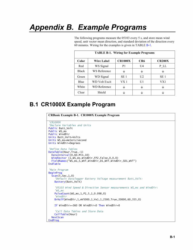
Appendix B. Example Programs The following programs measure the 05103 every 5 s, and store mean wind speed, unit vector mean direction, and standard deviation of the direction every 60 minutes. Wiring for the examples is given in TABLE B-1.
TABLE B-1. Wiring for Example Programs
Color Wire Label CR1000X CR6 CR200X Red WS Signal P1 U4 P_LL
Black WS Reference Green WD Signal SE 1 U2 SE 1 Blue WD Volt Excit VX 1 U1 VX1
White WD Reference Clear Shield
B.1 CR1000X Example Program
CRBasic Example B-1. CR1000X Example Program
'CR1000X 'Declare Variables and Units Public Batt_Volt Public WS_ms Public WindDir Units Batt_Volt=Volts Units WS_ms=meters/second Units WindDir=Degrees 'Define Data Tables DataTable(Hour,True,-1) DataInterval(0,60,Min,10) WindVector (1,WS_ms,WindDir,FP2,False,0,0,0) FieldNames("WS_ms_S_WVT,WindDir_D1_WVT,WindDir_SD1_WVT") EndTable 'Main Program BeginProg Scan(5,Sec,1,0) 'Default Datalogger Battery Voltage measurement Batt_Volt: Battery(Batt_Volt) '05103 Wind Speed & Direction Sensor measurements WS_ms and WindDir: 'WS_ms PulseCount(WS_ms,1,P1,5,1,0.098,0) 'WindDir BrHalf(WindDir,1,mV5000,1,Vx1,1,2500,True,20000,60,355,0) If WindDir>=360 OR WindDir<0 Then WindDir=0 'Call Data Tables and Store Data CallTable(Hour) NextScan EndProg
Appendix B. Example Programs
B-2
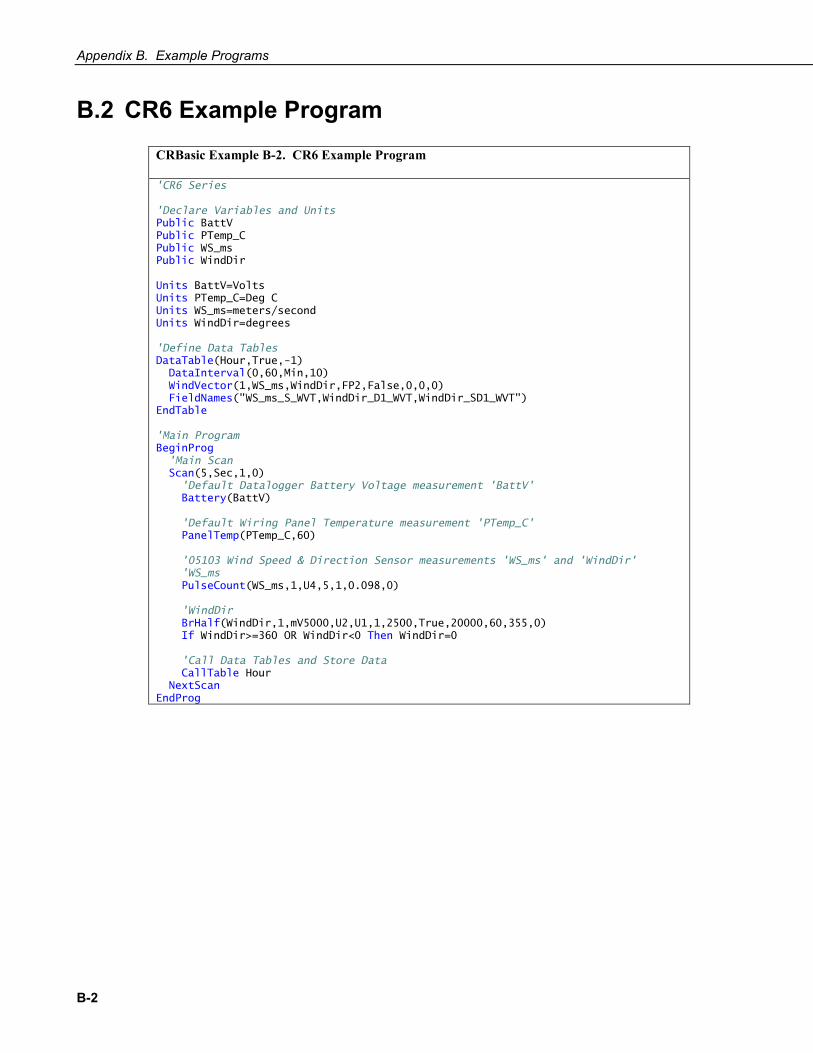
B.2 CR6 Example Program
CRBasic Example B-2. CR6 Example Program
'CR6 Series 'Declare Variables and Units Public BattV Public PTemp_C Public WS_ms Public WindDir Units BattV=Volts Units PTemp_C=Deg C Units WS_ms=meters/second Units WindDir=degrees 'Define Data Tables DataTable(Hour,True,-1) DataInterval(0,60,Min,10) WindVector(1,WS_ms,WindDir,FP2,False,0,0,0) FieldNames("WS_ms_S_WVT,WindDir_D1_WVT,WindDir_SD1_WVT") EndTable 'Main Program BeginProg 'Main Scan Scan(5,Sec,1,0) 'Default Datalogger Battery Voltage measurement 'BattV' Battery(BattV) 'Default Wiring Panel Temperature measurement 'PTemp_C' PanelTemp(PTemp_C,60) '05103 Wind Speed & Direction Sensor measurements 'WS_ms' and 'WindDir' 'WS_ms PulseCount(WS_ms,1,U4,5,1,0.098,0) 'WindDir BrHalf(WindDir,1,mV5000,U2,U1,1,2500,True,20000,60,355,0) If WindDir>=360 OR WindDir<0 Then WindDir=0 'Call Data Tables and Store Data CallTable Hour NextScan EndProg
Appendix B. Example Programs
B-3
B.3 CR200(X) Example Program
CRBasic Example B-3. CR200(X) Example Program
'CR200/CR200X Series 'Declare Variables and Units Public BattV Public WS_ms Public WindDir Units BattV=Volts Units WS_ms=meters/second Units WindDir=degrees 'Define Data Tables DataTable(Hour,True,-1) DataInterval(0,60,Min) WindVector(WS_ms,WindDir,False,0,0) FieldNames("WS_ms_S_WVT,WindDir_D1_WVT,WindDir_SD1_WVT") EndTable 'Main Program BeginProg 'Main Scan Scan(5,Sec) 'Default Datalogger Battery Voltage measurement 'BattV' Battery(BattV) '05103 Wind Speed & Direction Sensor measurements 'WS_ms' and 'WindDir' 'WS_ms PulseCount(WS_ms,P_LL,1,1,0.098,0) 'WindDir ExDelSE(WindDir,1,1,1,mV2500,20000,0.142,0) If WindDir>=360 Or WindDir<0 Then WindDir=0 'Call Data Tables and Store Data CallTable Hour NextScan EndProg

C-1
Appendix C. Wind Direction Sensor Orientation C.1 Determining True North and Sensor Orientation
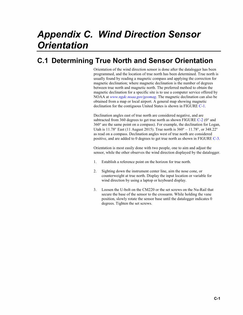
Orientation of the wind direction sensor is done after the datalogger has been programmed, and the location of true north has been determined. True north is usually found by reading a magnetic compass and applying the correction for magnetic declination; where magnetic declination is the number of degrees between true north and magnetic north. The preferred method to obtain the magnetic declination for a specific site is to use a computer service offered by NOAA at www.ngdc.noaa.gov/geomag. The magnetic declination can also be obtained from a map or local airport. A general map showing magnetic declination for the contiguous United States is shown in FIGURE C-1.
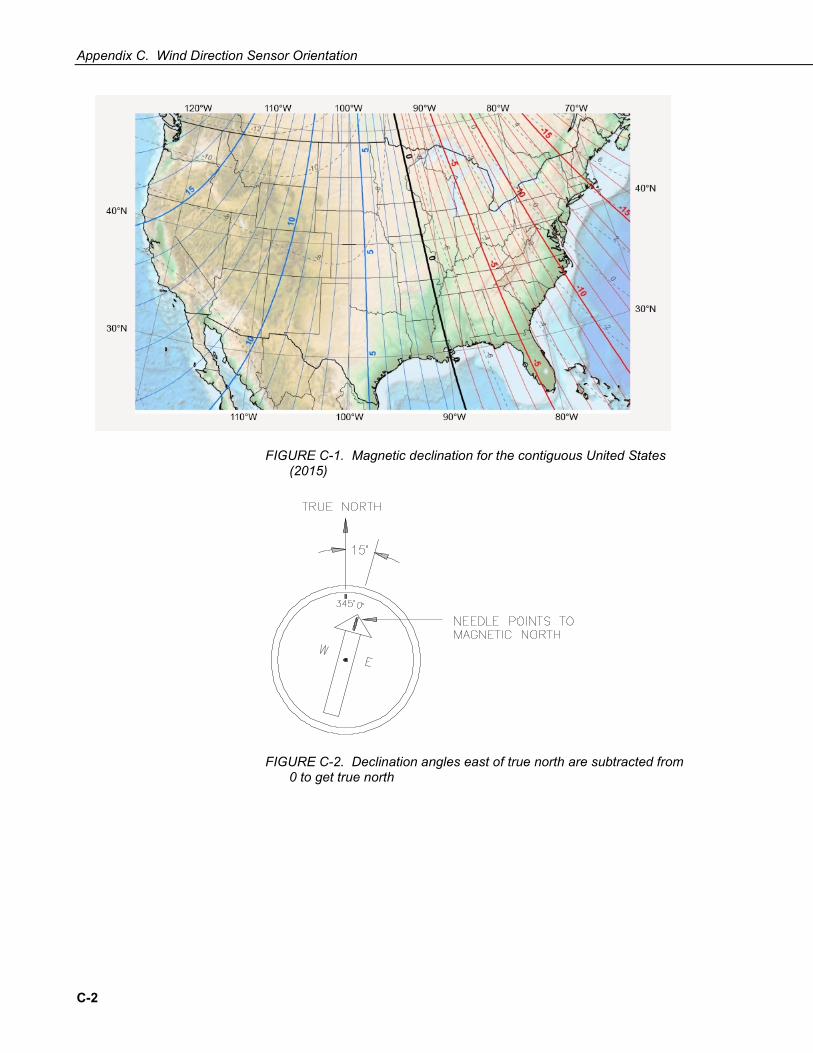
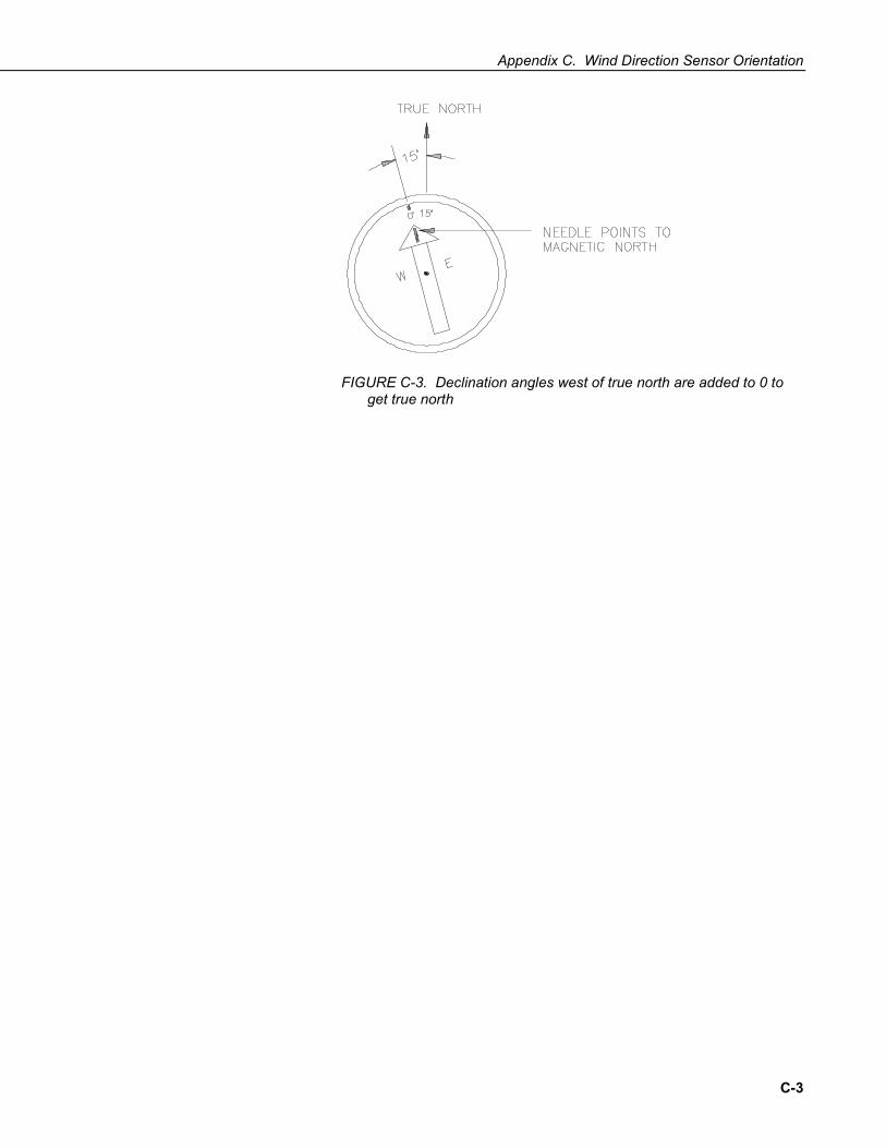
Declination angles east of true north are considered negative, and are subtracted from 360 degrees to get true north as shown FIGURE C-2 (0° and 360° are the same point on a compass). For example, the declination for Logan, Utah is 11.78° East (11 August 2015). True north is 360° – 11.78°, or 348.22° as read on a compass. Declination angles west of true north are considered positive, and are added to 0 degrees to get true north as shown in FIGURE C-3.
Orientation is most easily done with two people, one to aim and adjust the sensor, while the other observes the wind direction displayed by the datalogger.
1. Establish a reference point on the horizon for true north.
2. Sighting down the instrument center line, aim the nose cone, or counterweight at true north. Display the input location or variable for wind direction by using a laptop or keyboard display.
3. Loosen the U-bolt on the CM220 or the set screws on the Nu-Rail that secure the base of the sensor to the crossarm. While holding the vane position, slowly rotate the sensor base until the datalogger indicates 0 degrees. Tighten the set screws.
Appendix C. Wind Direction Sensor Orientation
C-2
FIGURE C-1. Magnetic declination for the contiguous United States (2015)
FIGURE C-2. Declination angles east of true north are subtracted from 0 to get true north
Appendix C. Wind Direction Sensor Orientation
C-3
FIGURE C-3. Declination angles west of true north are added to 0 to get true north

D-1
Appendix D. Wind Direction Measurement Theory
It is not necessary to understand the concepts in this section for the general operation of the 05103 with a Campbell Scientific datalogger.
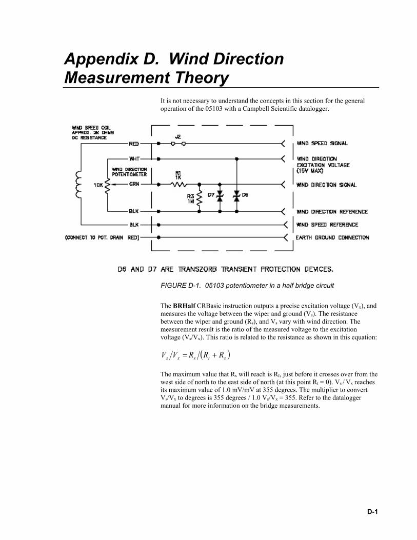
FIGURE D-1. 05103 potentiometer in a half bridge circuit
The BRHalf CRBasic instruction outputs a precise excitation voltage (Vx), and measures the voltage between the wiper and ground (Vs). The resistance between the wiper and ground (Rs), and Vs vary with wind direction. The measurement result is the ratio of the measured voltage to the excitation voltage (Vs/Vx). This ratio is related to the resistance as shown in this equation:
( )stsxs RRRVV +=
The maximum value that Rs will reach is Rf, just before it crosses over from the west side of north to the east side of north (at this point Rt = 0). Vs / Vx reaches its maximum value of 1.0 mV/mV at 355 degrees. The multiplier to convert Vs/Vx to degrees is 355 degrees / 1.0 Vs/Vx = 355. Refer to the datalogger manual for more information on the bridge measurements.


Campbell Scientific Worldwide Offices
Australia Location: Garbutt, QLD Australia Email: [email protected]
Website: www.campbellsci.com.au
Germany Location: Bremen, Germany Email: [email protected]
Website: www.campbellsci.de
Brazil Location: São Paulo, SP Brazil
Email: [email protected] Website: www.campbellsci.com.br
South Africa Location: Stellenbosch, South Africa
Email: [email protected] Website: www.campbellscientific.co.za
Canada Location: Edmonton, AB Canada
Email: [email protected] Website: www.campbellsci.ca
Southeast Asia Location: Bangkok, Thailand Email: [email protected]
Website: www.campbellsci.asia
China Location: Beijing, P. R. China
Email: [email protected] Website: www.campbellsci.com.cn
Spain Location: Barcelona, Spain Email: [email protected]
Website: www.campbellsci.es
Costa Rica Location: San José, Costa Rica
Email: [email protected] Website: www.campbellsci.cc
UK Location: Shepshed, Loughborough, UK
Email: [email protected] Website: www.campbellsci.co.uk
France Location: Antony, France
Email: [email protected] Website: www.campbellsci.fr
USA Location: Logan, UT USA
Email: [email protected] Website: www.campbellsci.com
Please visit www.campbellsci.com/contact to obtain contact information for your local US or international representative.


![ENERGY NEWS - orfonline.org · WEEK IN REVIEW] ENERGY NEWS MONITOR ANALYSIS / ... contract Mari Petroleum ... Suzlon bags wind turbine order for 197 MW](https://static.fdocuments.net/doc/165x107/5b59eb567f8b9a6c4f8dc9c7/energy-news-week-in-review-energy-news-monitor-analysis-contract-mari.jpg)