Wind Induced Vibration of Cable Stay Bridges … Induced Vibration of Cable Stay Bridges Workshop,...
78
Wind Induced Vibration of Cable Stay Bridges Workshop, April 25- 27, 2006 Review of Bridge Cable Vibrations in Japan The practical Cases of Aerodynamic Vibration of Stayed Cables Masaru MATSUMOTO Kyoto University Kyoto, JAPAN
Transcript of Wind Induced Vibration of Cable Stay Bridges … Induced Vibration of Cable Stay Bridges Workshop,...

Wind Induced Vibration of Cable Stay Bridges Workshop, April 25-27, 2006
Review of Bridge Cable Vibrations in Japan
The practical Cases of Aerodynamic Vibration of Stayed Cables
Masaru MATSUMOTOKyoto UniversityKyoto, JAPAN
Recent experiencesRecent experiencesfor cable vibrationsfor cable vibrations
Cable Aerodynamic Vibration
In various countries, it has been observed. Probably, all countries where cable stayed bridges have been constructed, might have those experiences.
Belgium, China, Denmark, France, German, Holland, Japan, Nepal, USA and others
Practical wind-induced cable vibration of cable-stayed bridges
Karman vortex excitation
Wake galloping
Rain-wind induced vibration
Dry-state galloping
Rain-Wind Induced Vibrations
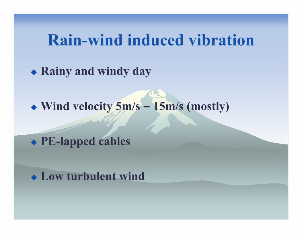
Rain-wind induced vibration
Rainy and windy day
Wind velocity 5m/s – 15m/s (mostly)
PE-lapped cables
Low turbulent wind
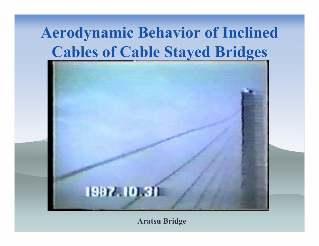
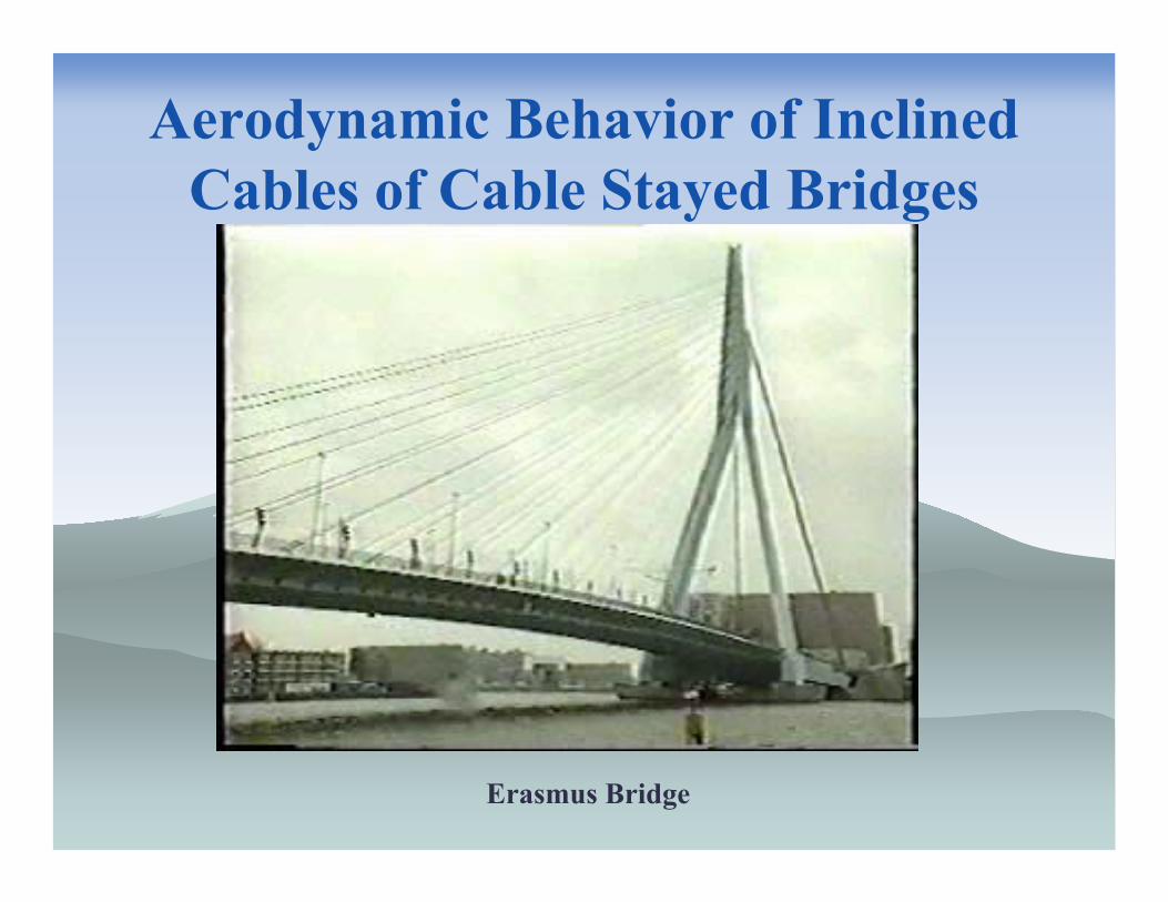
Aerodynamic Behavior of Inclined Cables of Cable Stayed Bridges
Aratsu Bridge
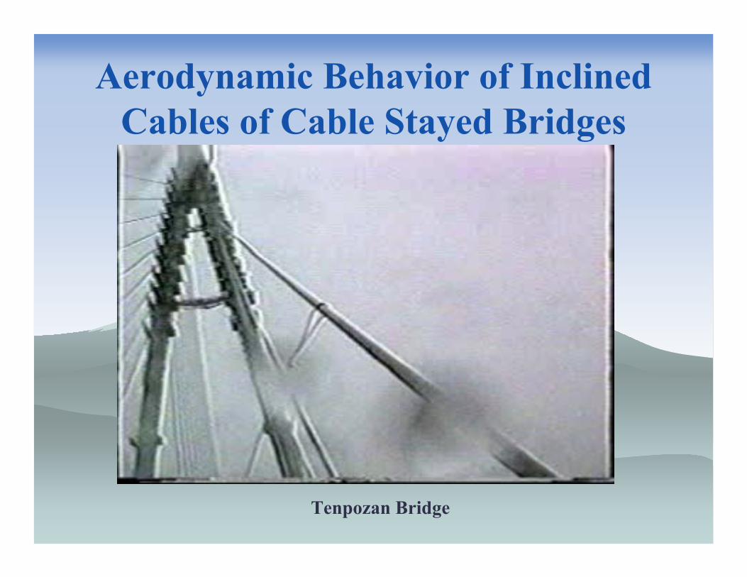
Aerodynamic Behavior of Inclined Cables of Cable Stayed Bridges
Tenpozan Bridge
Aerodynamic Behavior of Inclined Cables of Cable Stayed Bridges
Erasmus Bridge
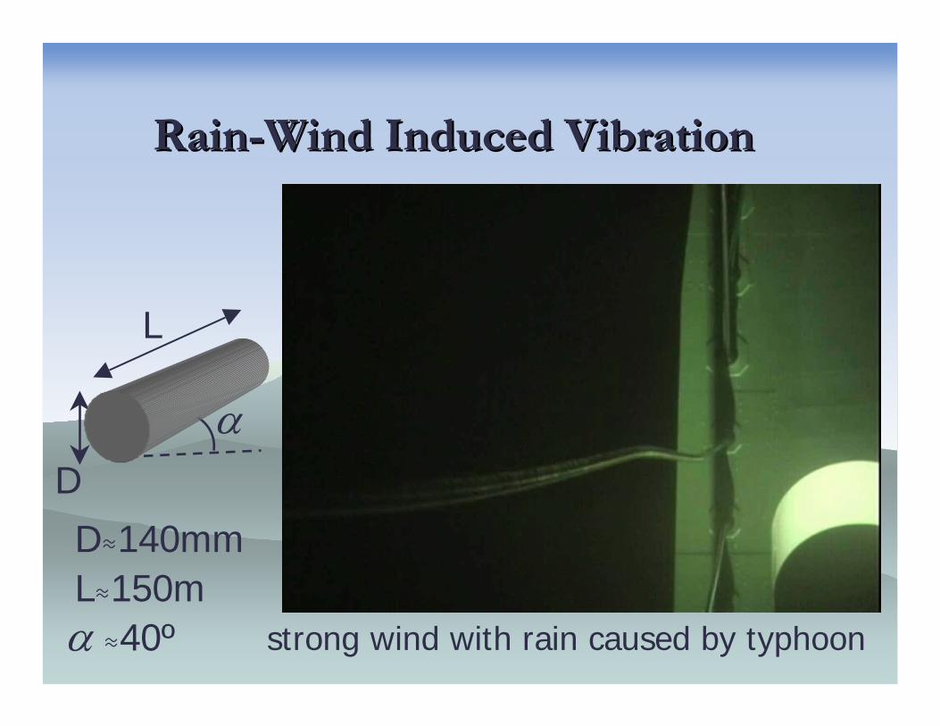
RainRain--Wind Induced VibrationWind Induced Vibration
D
L
α
D≈140mmL≈150mα ≈40º strong wind with rain caused by typhoon
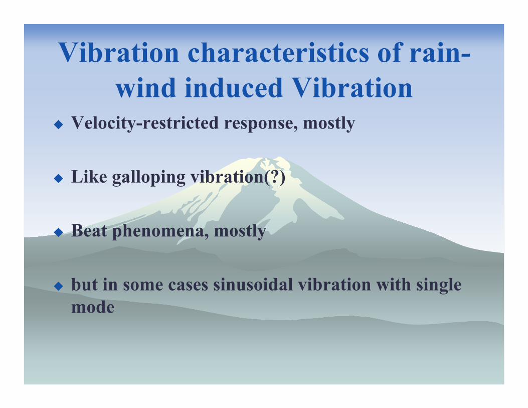
Vibration characteristics of rain-wind induced Vibration
Velocity-restricted response, mostly
Like galloping vibration(?)
Beat phenomena, mostly
but in some cases sinusoidal vibration with single mode
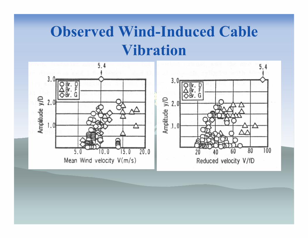
Observed Wind-Induced Cable Vibration
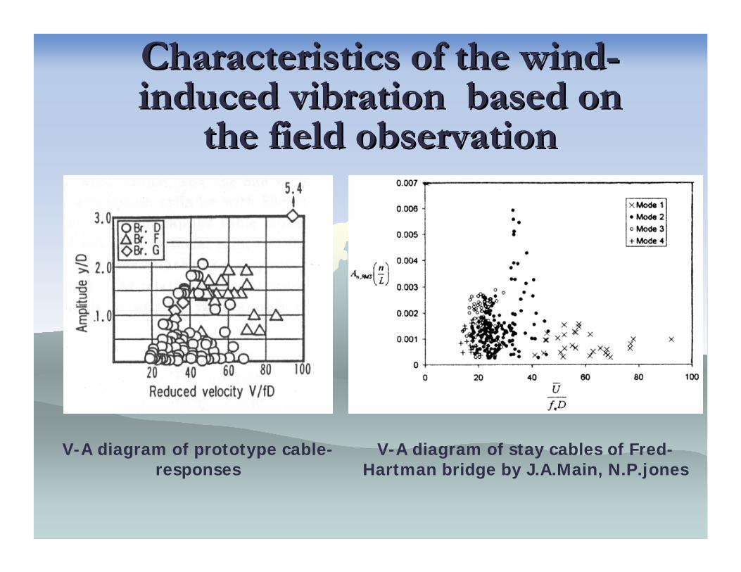
Characteristics of the windCharacteristics of the wind--induced vibration based on induced vibration based on
the field observationthe field observation
V-A diagram of prototype cable-responses
V-A diagram of stay cables of Fred-Hartman bridge by J.A.Main, N.P.jones
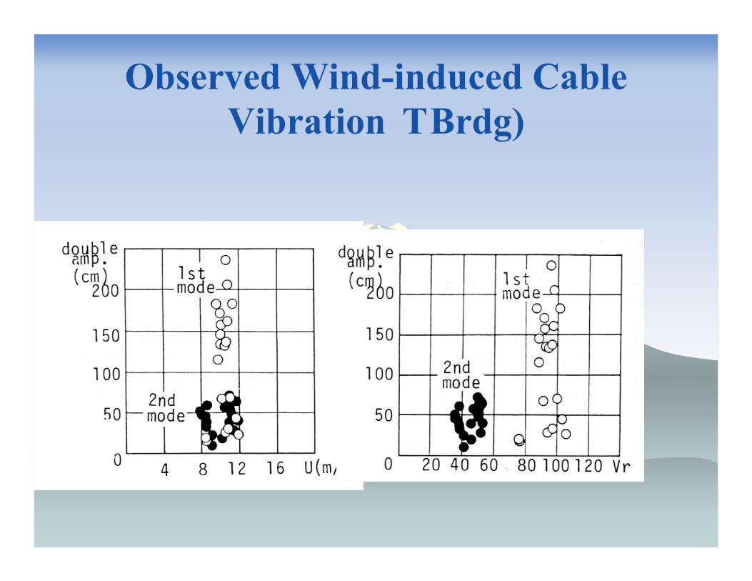
Observed Wind-induced Cable Vibration�T Brdg)
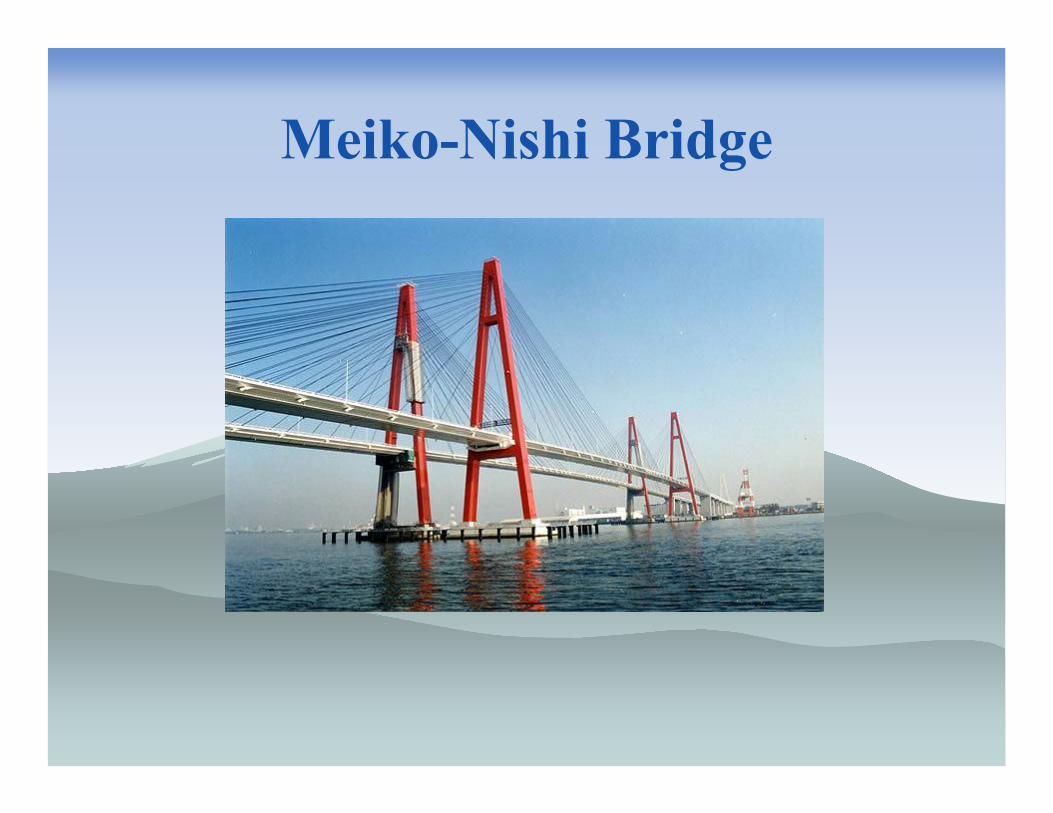
Meiko-Nishi Bridge
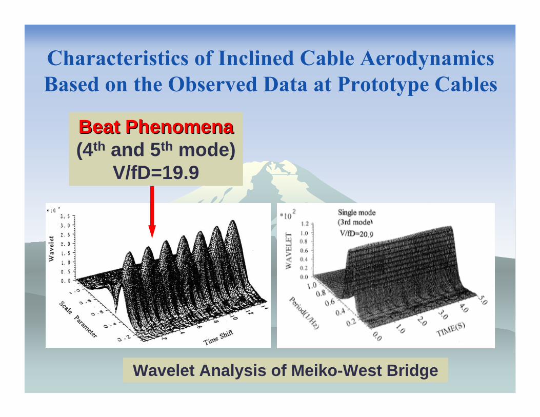
Wavelet Analysis of Meiko-West Bridge
Characteristics of Inclined Cable AerodynamicsBased on the Observed Data at Prototype Cables
Beat PhenomenaBeat Phenomena(4th and 5th mode)
V/fD=19.9

RainRain--Wind Induced VibrationWind Induced Vibration
D
L
α
D≈140mmL≈150mα ≈40º strong wind with rain caused by typhoon

Formation of upper water rivulet
Wind velocity
Wind direction to bridge axis
Vertical angle of cable
Cable surface material (PE)
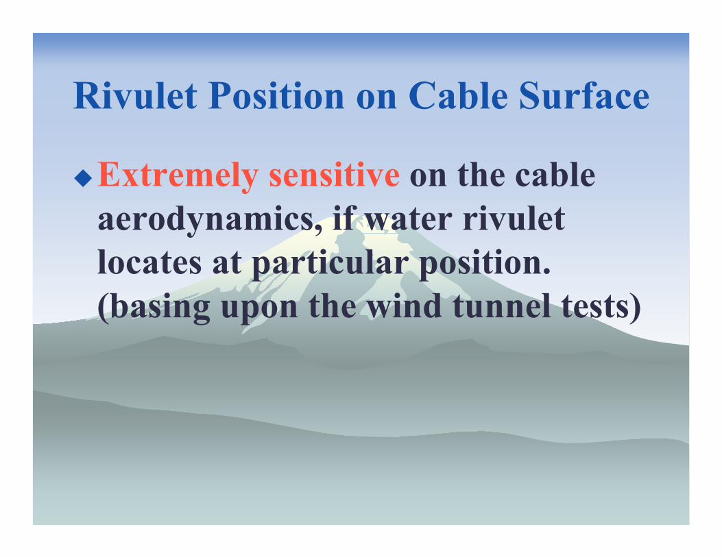
Rivulet Position on Cable Surface
Extremely sensitive on the cable aerodynamics, if water rivulet locates at particular position. (basing upon the wind tunnel tests)
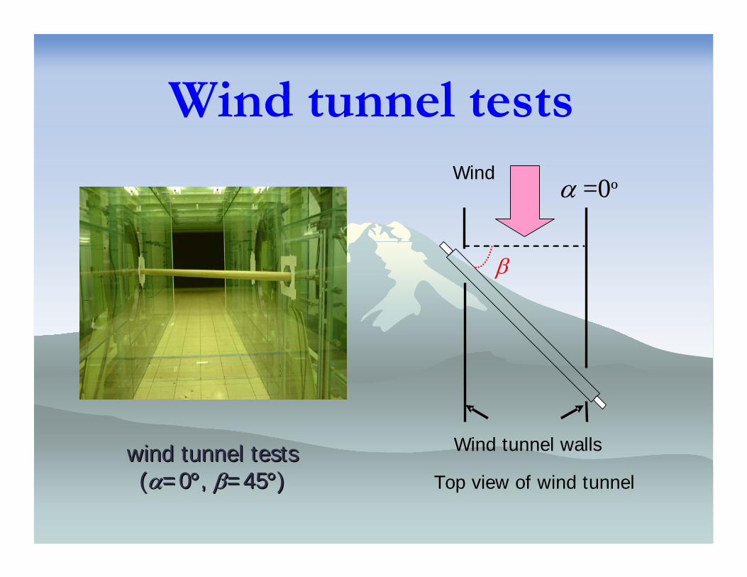
Wind tunnel tests
Top view of wind tunnel
Wind
Wind tunnel walls
β
α =0º
wind tunnel testswind tunnel tests((αα=0=0°°, , ββ=45=45°°) )
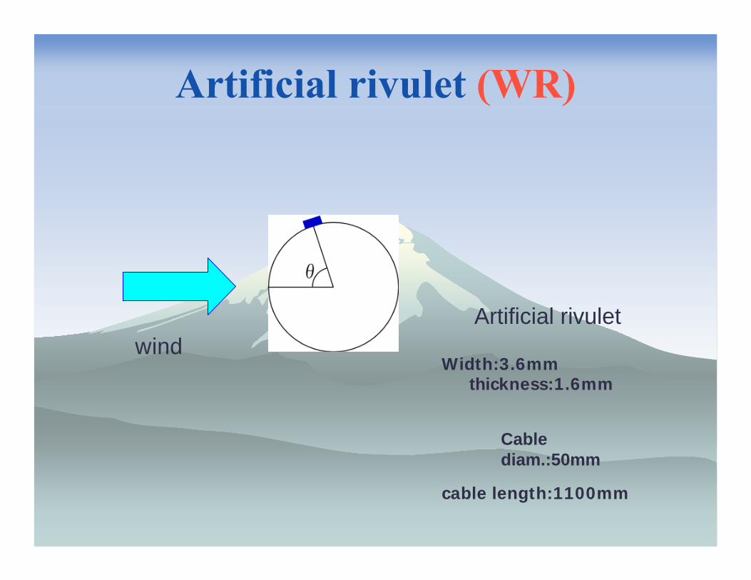
Artificial rivulet (WR)
wind
Cable diam.:50mm
Artificial rivulet
cable length:1100mm
Width:3.6mm�����thickness:1.6mm
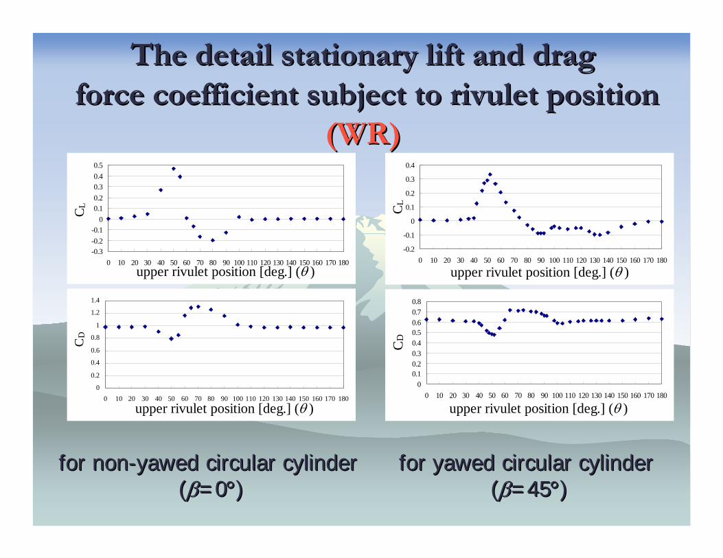
The detail stationary lift and dragThe detail stationary lift and dragforce coefficient subject to rivulet position force coefficient subject to rivulet position
(WR)(WR)
-0.3-0.2-0.1
00.10.20.30.40.5
0 10 20 30 40 50 60 70 80 90 100 110 120 130 140 150 160 170 180upper rivulet position [deg.] (θ )
C L
0
0.2
0.4
0.6
0.8
1
1.2
1.4
0 10 20 30 40 50 60 70 80 90 100 110 120 130 140 150 160 170 180
upper rivulet position [deg.] (θ )
CD
-0.2
-0.1
0
0.1
0.2
0.3
0.4
0 10 20 30 40 50 60 70 80 90 100 110 120 130 140 150 160 170 180
upper rivulet position [deg.] (θ )
C L0
0.10.20.30.40.50.60.70.8
0 10 20 30 40 50 60 70 80 90 100 110 120 130 140 150 160 170 180
upper rivulet position [deg.] (θ )C
D
for nonfor non--yawed yawed circular cylindercircular cylinder((ββ=0=0°°))
for yawed for yawed circular cylindercircular cylinder((ββ=45=45°°))
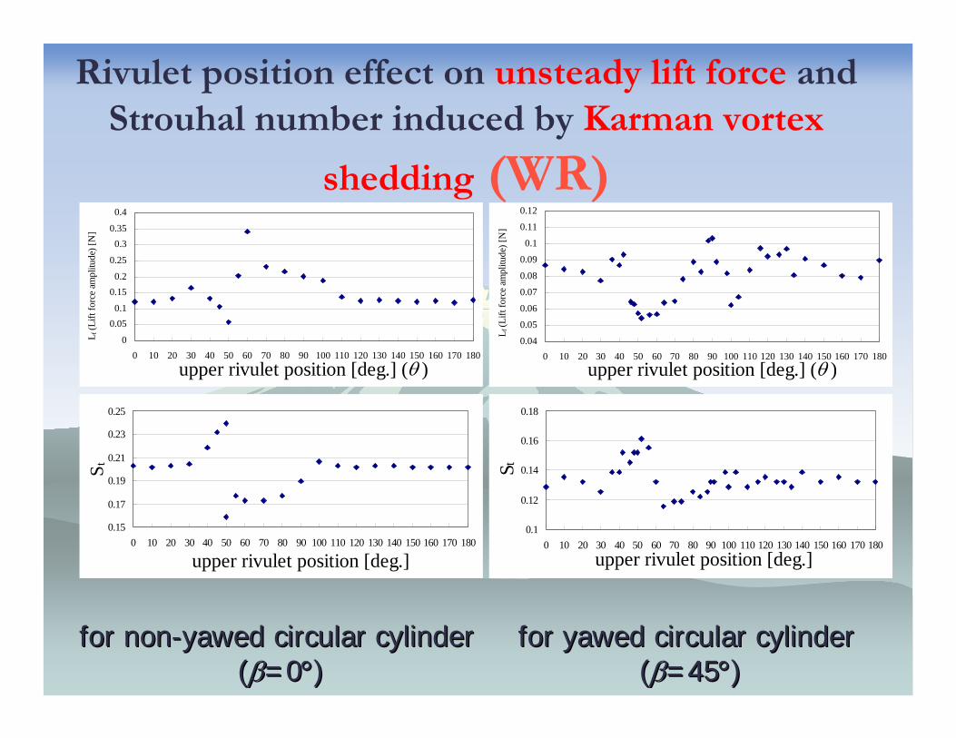
Rivulet position effect on unsteady lift force and Strouhal number induced by Karman vortex
shedding (WR)
0
0.050.1
0.150.2
0.25
0.30.35
0.4
0 10 20 30 40 50 60 70 80 90 100 110 120 130 140 150 160 170 180
upper rivulet position [deg.] (θ )
L f (L
ift fo
rce
ampl
itude
) [N
]
0.04
0.05
0.06
0.07
0.08
0.09
0.1
0.11
0.12
0 10 20 30 40 50 60 70 80 90 100 110 120 130 140 150 160 170 180
upper rivulet position [deg.] (θ )
L f (L
ift fo
rce
ampl
itude
) [N
]
for nonfor non--yawed yawed circular cylindercircular cylinder((ββ=0=0°°))
for yawed for yawed circular cylindercircular cylinder((ββ=45=45°°))
0.1
0.12
0.14
0.16
0.18
0 10 20 30 40 50 60 70 80 90 100 110 120 130 140 150 160 170 180upper rivulet position [deg.]
S t0.15
0.17
0.19
0.21
0.23
0.25
0 10 20 30 40 50 60 70 80 90 100 110 120 130 140 150 160 170 180
upper rivulet position [deg.]
S t
Movement of water rivulet during cable vibration(MHI)
Significantly complicated behavior and non-uniformly distribution along cable axis
Absolute condition of rivulet movement for vibration ?

Observed water rivulet movement on prototype Observed water rivulet movement on prototype scale cable model during rainscale cable model during rain--wind induced wind induced
vibrationvibration (MHI)(MHI)
V=10m/s
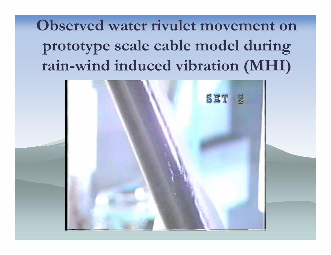
Observed water rivulet movement on prototype scale cable model during rain-wind induced vibration (MHI)
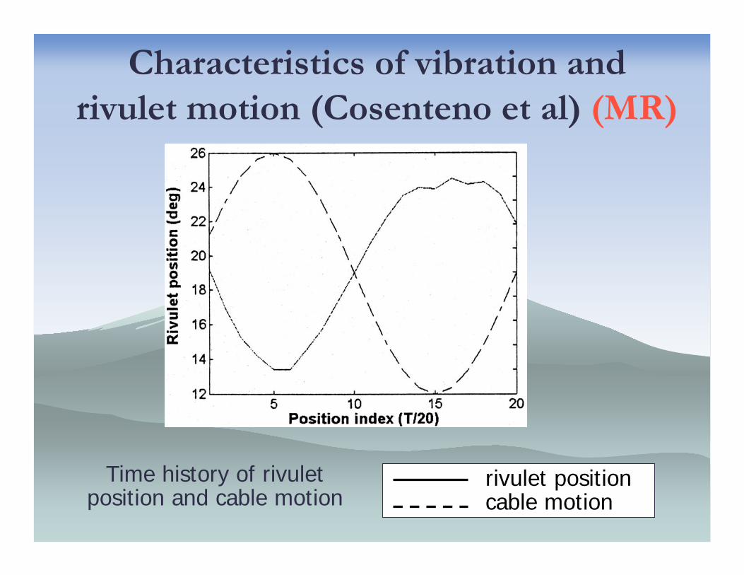
Characteristics of vibration and rivulet motion (Cosenteno et al) (MR)
Time history of rivulet position and cable motion
rivulet positioncable motion
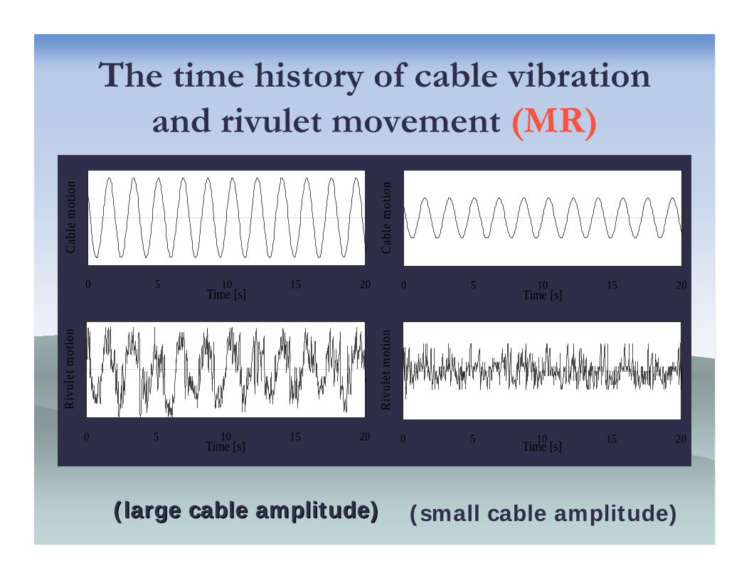
The time history of cable vibration and rivulet movement (MR)
0 5 10 15 20Time [s]
Cab
le m
otio
n
0 5 10 15 20Time [s]
Riv
ulet
mot
ion
0 5 10 15 20Time [s]
Cab
le m
otio
n
0 5 10 15 20Time [s]
Riv
ulet
mot
ion
(large cable amplitude)(large cable amplitude) (small cable amplitude)
Rivulet movement
Rivulet movement behaves non-uniformlyand non-stationary along cable axis even
stationary cross-flow vibration.
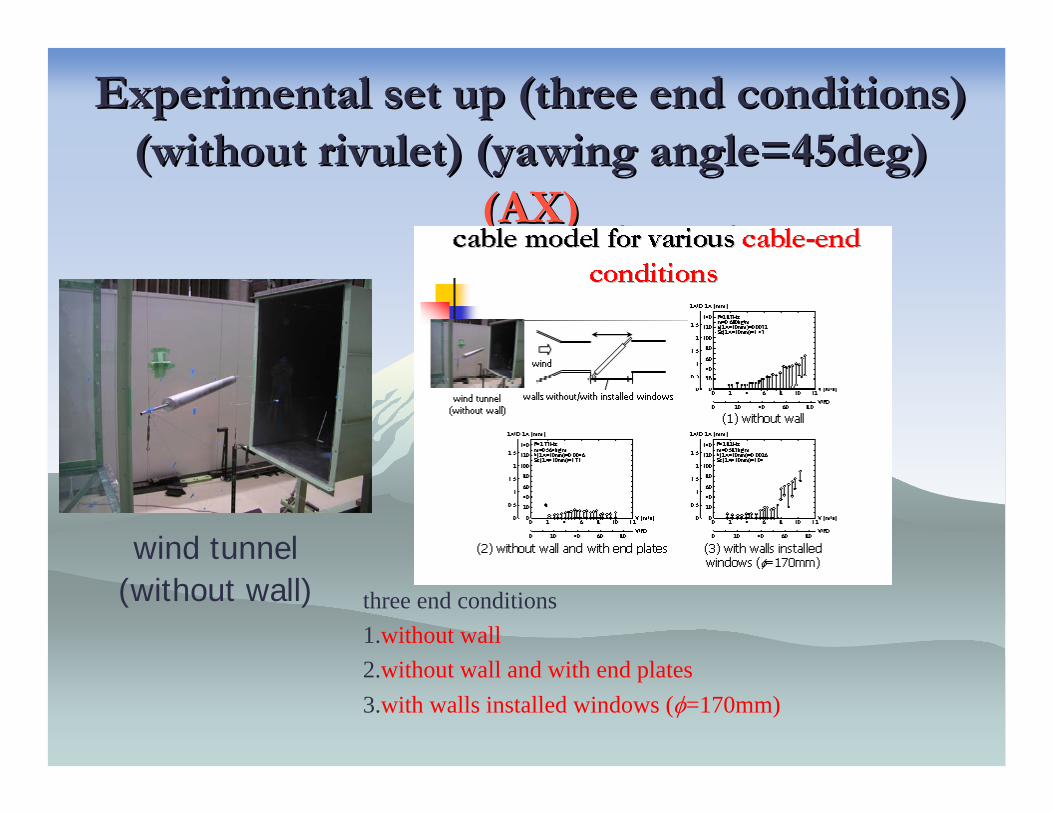
Experimental set up (three end conditions)Experimental set up (three end conditions)(without rivulet) (yawing angle=45deg) (without rivulet) (yawing angle=45deg)
(AX)(AX)
three end conditions1.without wall2.without wall and with end plates3.with walls installed windows (φ=170mm)
wind tunnel(without wall)
wind
walls and windows
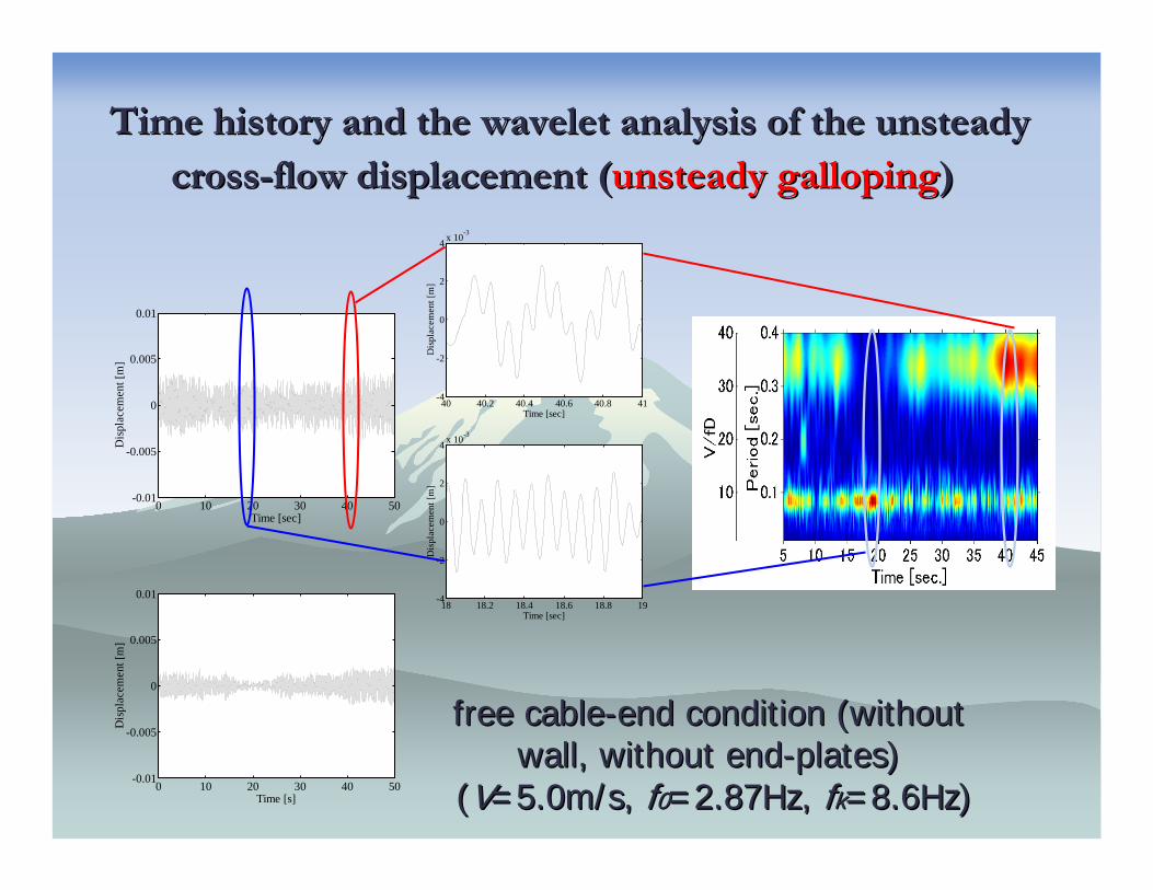
Time history and the wavelet analysis of the unsteady Time history and the wavelet analysis of the unsteady crosscross--flow displacement (flow displacement (unsteady gallopingunsteady galloping))
0 10 20 30 40 50-0.01
-0.005
0
0.005
0.01
Time [sec]
Dis
plac
emen
t [m
]
18 18.2 18.4 18.6 18.8 19-4
-2
0
2
4 x 10⁻³
Time [sec]
Dis
plac
emen
t [m
]
40 40.2 40.4 40.6 40.8 41-4
-2
0
2
4 x 10⁻³
Time [sec]
Dis
plac
emen
t [m
]
free cablefree cable--end condition (without end condition (without wall, without endwall, without end--plates)plates)
((VV=5.0m/s, =5.0m/s, ff00=2.87Hz, =2.87Hz, ffkk=8.6Hz)=8.6Hz)0 10 20 30 40 50-0.01
-0.005
0
0.005
0.01
Time [s]
Dis
plac
emen
t [m
]

The Role of Karman Vortex
Mitigation of Karman Vortex ��������������▼
▼
Galloping

Dry-State Galloping
Dry-state galloping
Sever vibration without rainAxial FlowCritical Reynolds number
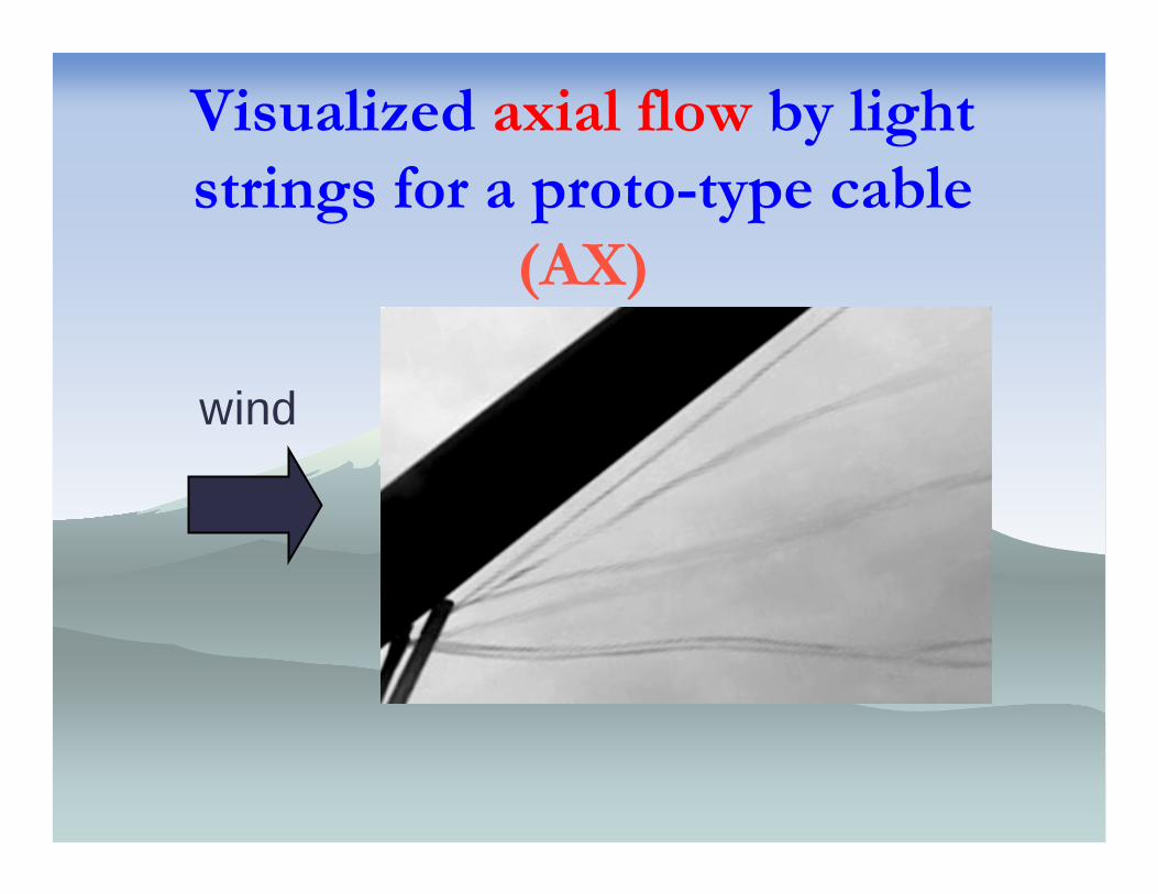
Visualized axial flow by light strings for a proto-type cable
(AX)
wind
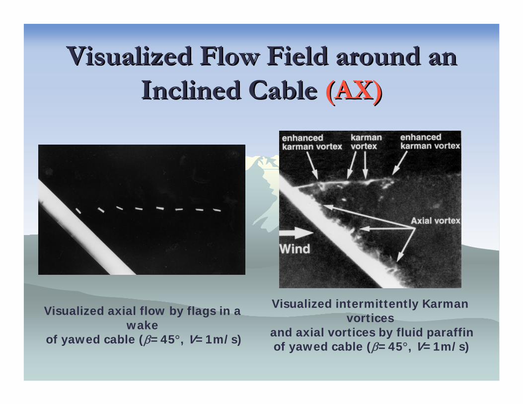
Visualized Flow Field around an Visualized Flow Field around an Inclined Cable Inclined Cable (AX)(AX)
Visualized axial flow by flags in a wake
of yawed cable (β=45°, V=1m/s)
Visualized intermittently Karman vortices
and axial vortices by fluid paraffinof yawed cable (β=45°, V=1m/s)
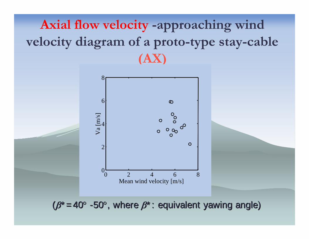
Axial flow velocity -approaching wind velocity diagram of a proto-type stay-cable
(AX)
((ββ*=40*=40°° --5050°°, where , where ββ*: equivalent yawing angle)*: equivalent yawing angle)
0 2 4 6 80
2
4
6
8
Mean wind velocity [m/s]
Va
[m/s
]
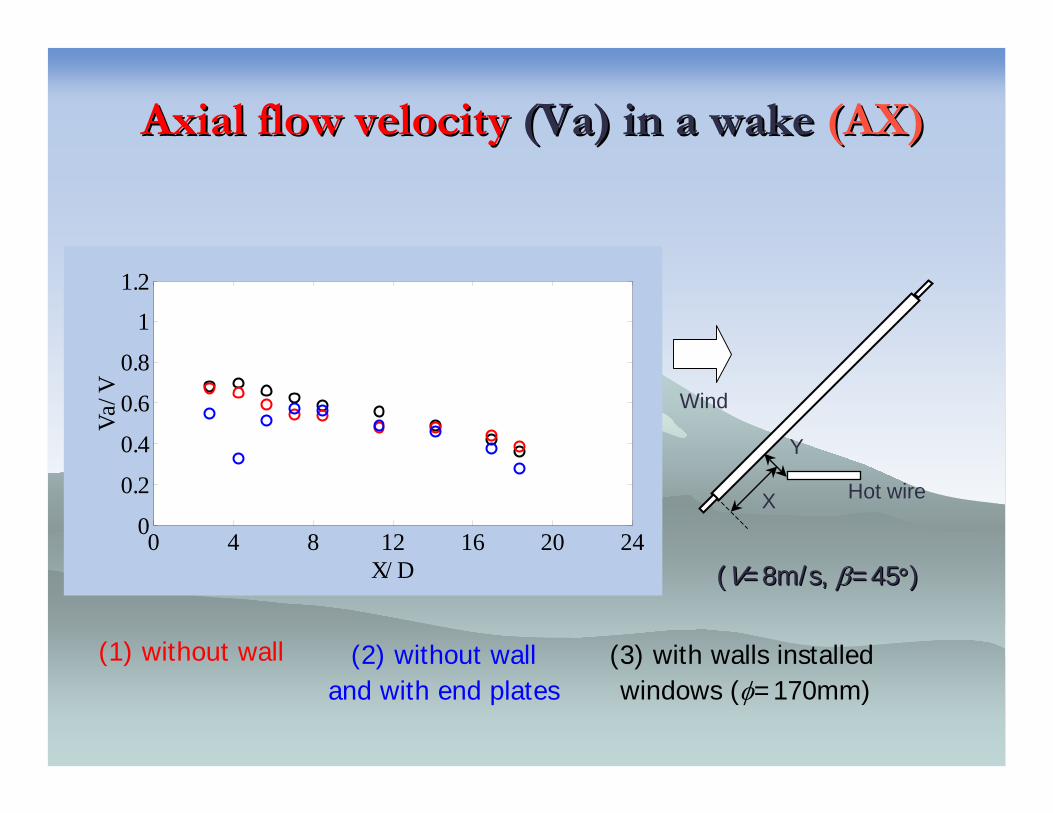
Axial flow velocityAxial flow velocity (Va) in a wake (Va) in a wake (AX)(AX)
0 4 8 12 16 20 240
0.2
0.4
0.6
0.8
1
1.2
X/ D
Va/V Wind
X
Y
Hot wire
(1) without wall (2) without wall and with end plates
(3) with walls installedwindows (φ=170mm)
((VV=8m/s, =8m/s, ββ=45=45°°))
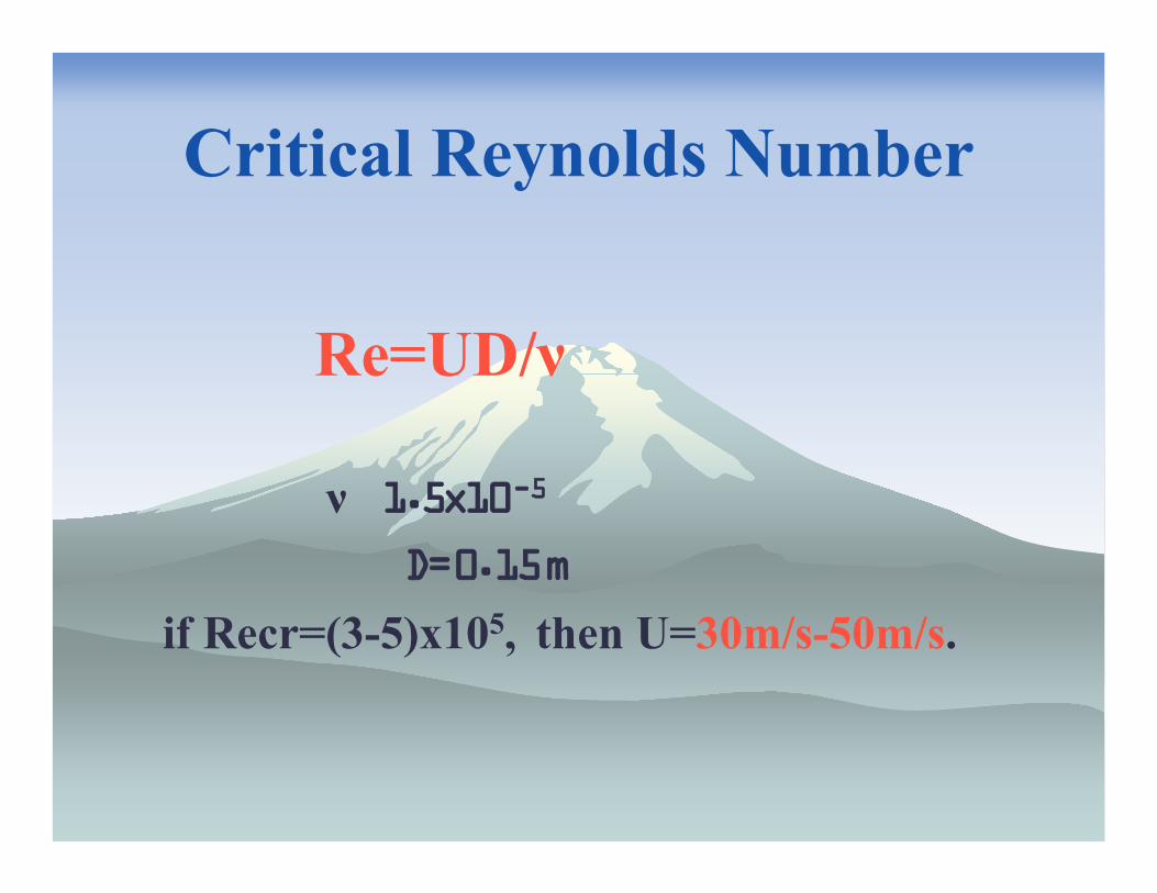
Critical Reynolds Number
Re=UD/ν
ν�1.5x10⁻⁵
D=0.15m
if Recr=(3-5)x105, then U=30m/s-50m/s.
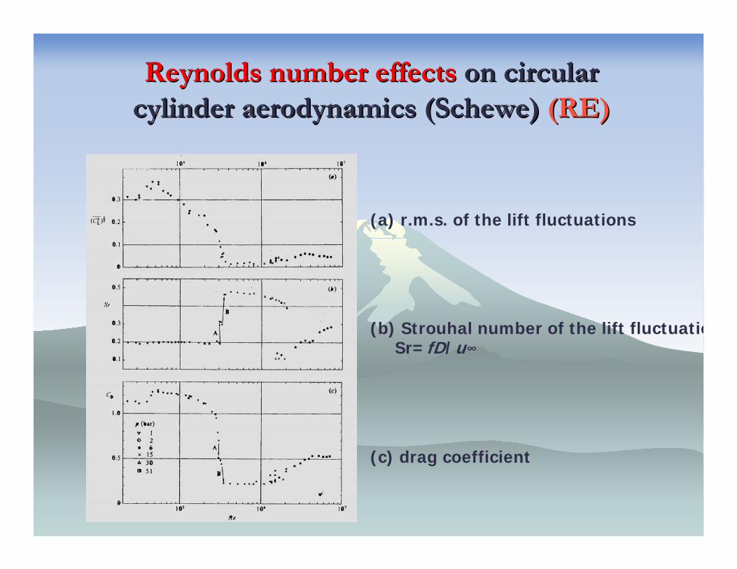
Reynolds number effectsReynolds number effects on circular on circular cylinder aerodynamics (cylinder aerodynamics (ScheweSchewe) ) (RE)(RE)
(a) r.m.s. of the lift fluctuations
(b) Strouhal number of the lift fluctuatioSr=fD/u∞
(c) drag coefficient
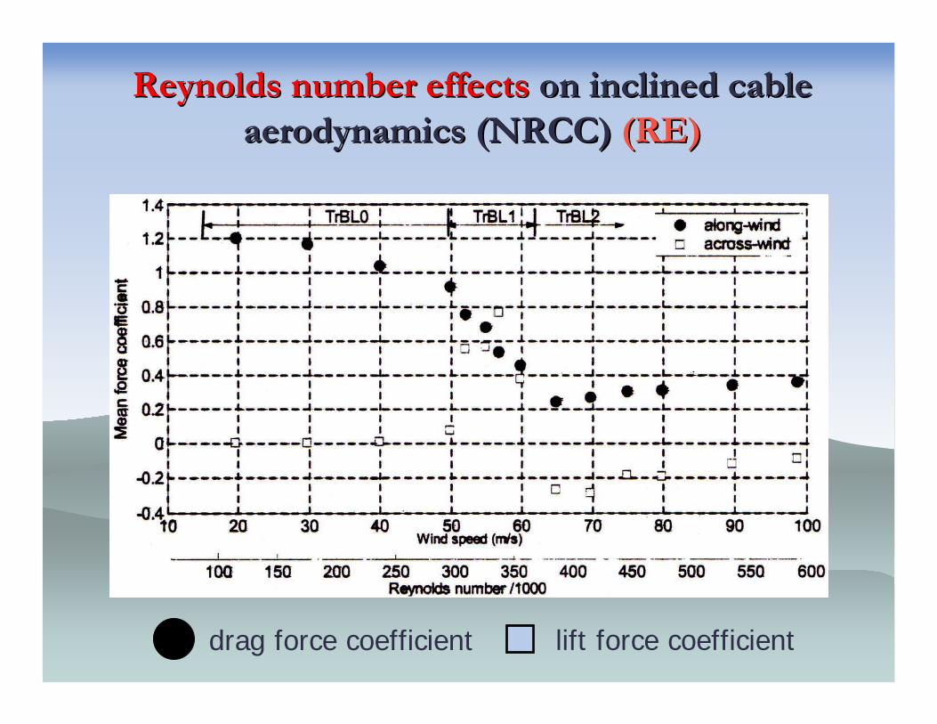
Reynolds number effectsReynolds number effects on inclined cable on inclined cable aerodynamics (NRCC) aerodynamics (NRCC) (RE)(RE)
lift force coefficientdrag force coefficient
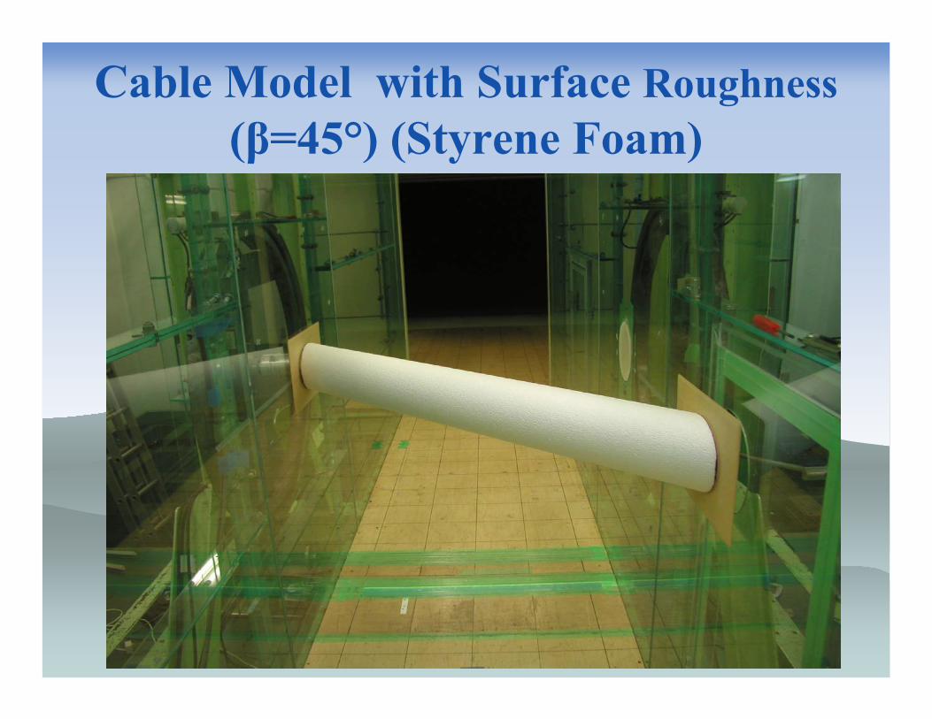
Cable Model with Surface Roughness(β=45°) (Styrene Foam)
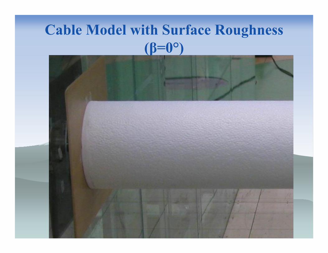
Cable Model with Surface Roughness (β=0°)
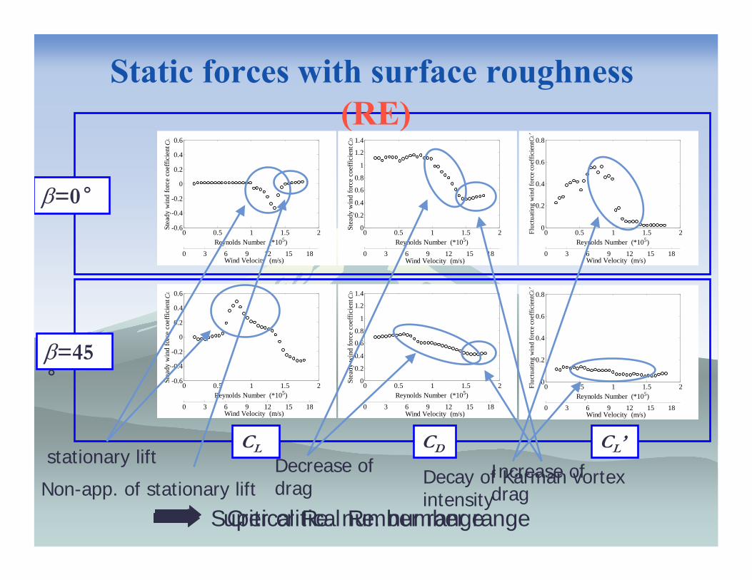
Static forces�with surface roughness�(RE)
0 0.5 1 1.5 20
0.2
0.4
0.6
0.8
1
1.2
1.4
Reynolds Number (*105)
Stea
dy w
ind
forc
e co
effic
ient
CD
Wind Velocity (m/s)0 3 6 9 12 15 18
0 0.5 1 1.5 2-0.6
-0.4
-0.2
0
0.2
0.4
0.6
Reynolds Number (*105)
Stea
dy w
ind
forc
e co
effic
ient
CL
Wind Velocity (m/s)0 3 6 9 12 15 18
0 0.5 1 1.5 20
0.2
0.4
0.6
0.8
Reynolds Number (*105)
Fluc
tuat
ing
win
d fo
rce
coef
ficie
nt CL
′
Wind Velocity (m/s)0 3 6 9 12 15 18
0 0.5 1 1.5 20
0.2
0.4
0.6
0.8
Reynolds Number (*105)
Fluc
tuat
ing
win
d fo
rce
coef
ficie
nt CL
′
Wind Velocity (m/s)0 3 6 9 12 15 18
0 0.5 1 1.5 20
0.2
0.4
0.6
0.8
1
1.2
1.4
Reynolds Number (*105)
Stea
dy w
ind
forc
e co
effic
ient
CD
Wind Velocity (m/s)0 3 6 9 12 15 18
0 0.5 1 1.5 2-0.6
-0.4
-0.2
0
0.2
0.4
0.6
Reynolds Number (*105)
Stea
dy w
ind
forc
e co
effic
ient
CL
Wind Velocity (m/s)0 3 6 9 12 15 18
β=0˚
CL CD CL’Decrease of drag
stationary liftDecay of Karman vortex intensity
Critical Re. number range
Increase of dragNon-app. of stationary lift
β=45˚
Super critical Re. number range
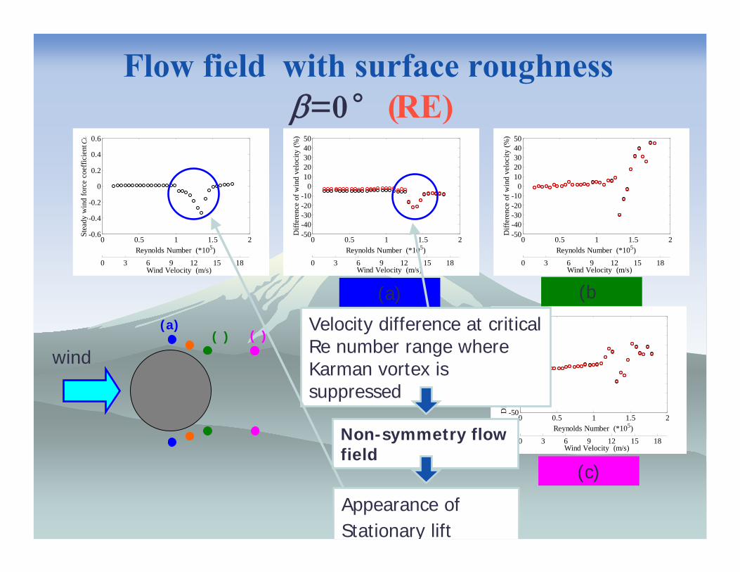
Flow field�with surface roughness�β=0 �̊(RE)
0 0.5 1 1.5 2-50-40-30-20-10
01020304050
Reynolds Number (*105)
Diff
eren
ce o
f win
d ve
loci
ty (%
)
Wind Velocity (m/s)0 3 6 9 12 15 18
0 0.5 1 1.5 2-50-40-30-20-10
01020304050
Reynolds Number (*105)
Diff
eren
ce o
f win
d ve
loci
ty (%
)
Wind Velocity (m/s)0 3 6 9 12 15 18
0 0.5 1 1.5 2-50-40-30-20-10
01020304050
Reynolds Number (*105)
Diff
eren
ce o
f win
d ve
loci
ty (%
)
Wind Velocity (m/s)0 3 6 9 12 15 18
wind
(a)(�) (�)
0 0.5 1 1.5 2-0.6
-0.4
-0.2
0
0.2
0.4
0.6
Reynolds Number (*105)
Stea
dy w
ind
forc
e co
effic
ient
CL
Wind Velocity (m/s)0 3 6 9 12 15 18
(a)
(c)
(b�
Velocity difference at critical Re number range where Karman vortex is suppressed
Non-symmetry flow field
Appearance of Stationary lift
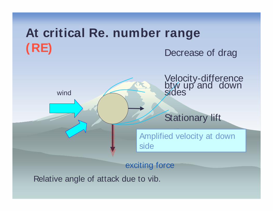
At critical Re. number range (RE) Decrease of drag
Velocity-difference btw up and down sides
Stationary lift
wind
Relative angle of attack due to vib.
Amplified velocity at down side
exciting force
The Role of Karman Vortex
Mitigation of Karman Vortex ��������������▼
▼
Galloping
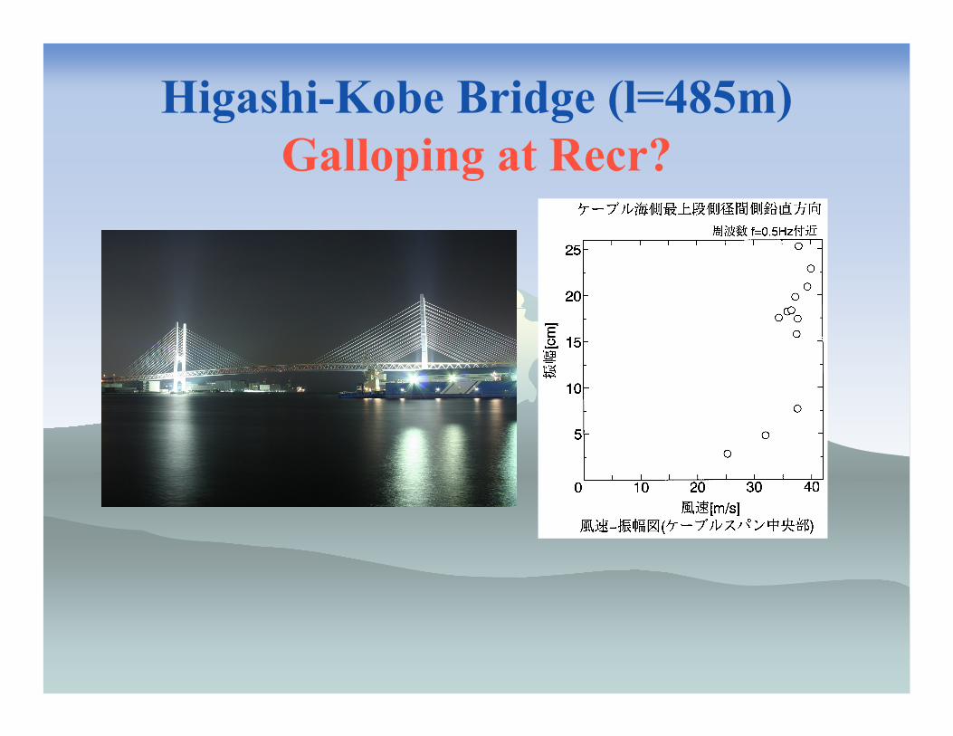
Higashi-Kobe Bridge (l=485m)Galloping at Recr?

The Aerodynamic Countermeasures for Cable
Vibration Control
Axial protuberances(Higashi Kobe Bridge)
Dimples(Tatara Bridge)
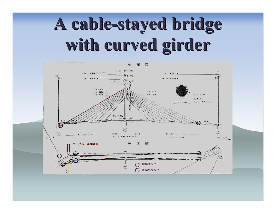
A cableA cable--stayed bridge stayed bridge with curved girderwith curved girder
Reference Inclined CableLength
approximately 200mCable Surface material
lapped by PEVibration Frequency
1.0 Hz (2nd mode) ?
Climate ConditionWind velocity
18-19m/s (mean wind velocity)Wind direction to cable
about 20-45degree ?Rain
stopped during sever vibration

Violent cable vibration (Violent cable vibration (DryDry--State GallopingState Galloping? without rain)? without rain)
(Typhoon, 2004)(Typhoon, 2004)
without rain (courtesy of Mr. H. Yoshikawa)
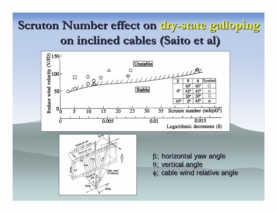
Scruton Scruton NumberNumber effect on effect on drydry--state gallopingstate gallopingon inclined cables (Saito et al)on inclined cables (Saito et al)
ββ; horizontal yaw angle; horizontal yaw angleθθ; vertical angle; vertical angleφφ; cable wind relative angle; cable wind relative angle
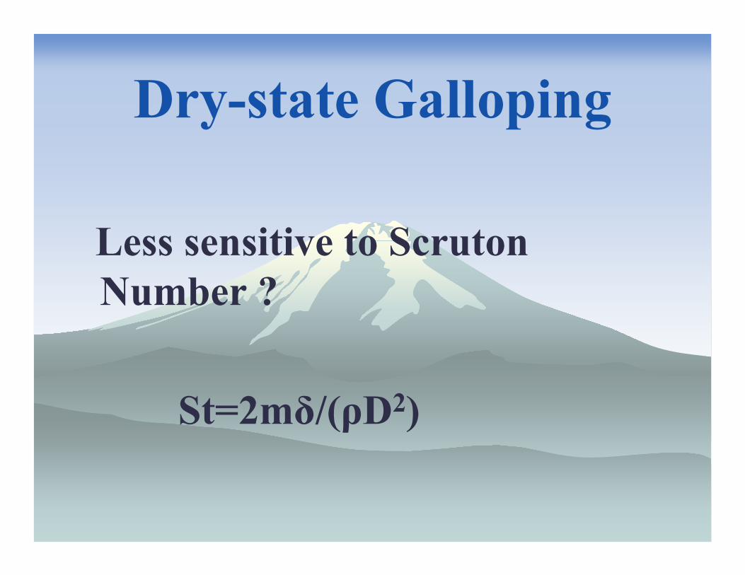
Dry-state Galloping
Less sensitive to ScrutonNumber ?
St=2mδ/(ρD2)
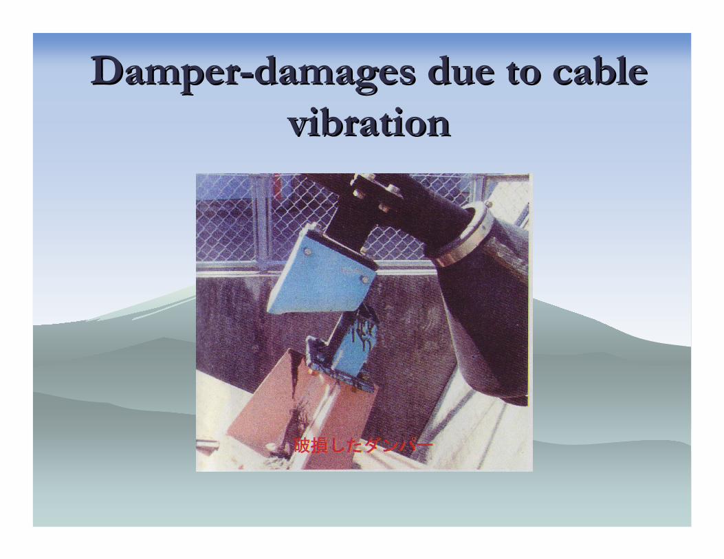
DamperDamper--damages due to cable damages due to cable vibrationvibration
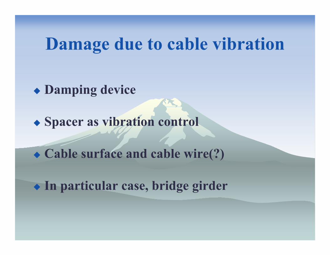
Damage due to cable vibration
Damping device
Spacer as vibration control
Cable surface and cable wire(?)
In particular case, bridge girder
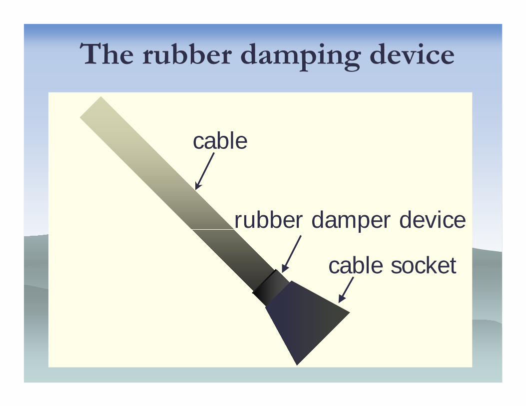
The rubber damping device
cable
cable socket
rubber damper device
Damages of Cable and damper
Rubber cover prevented to detect the inside details
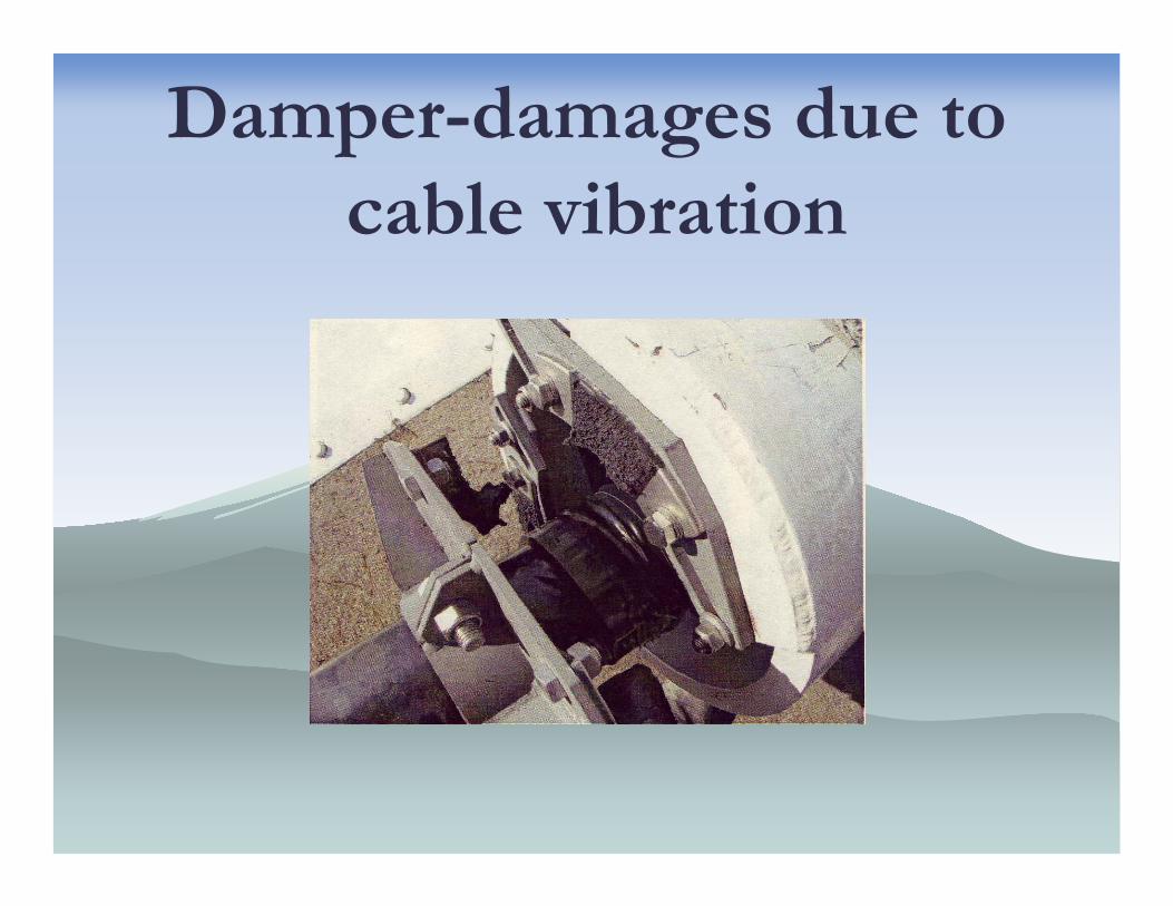
Damper-damages due tocable vibration

CableCable--damages due to cable damages due to cable vibrationvibration
Periodical Inspection of Damping Devices
The damping devices of stay cables should be periodically inspected, in particular immediately after sever storm or sever gale.
Vibration ControlStructural countermeasures
Aerodynamic countermeasures
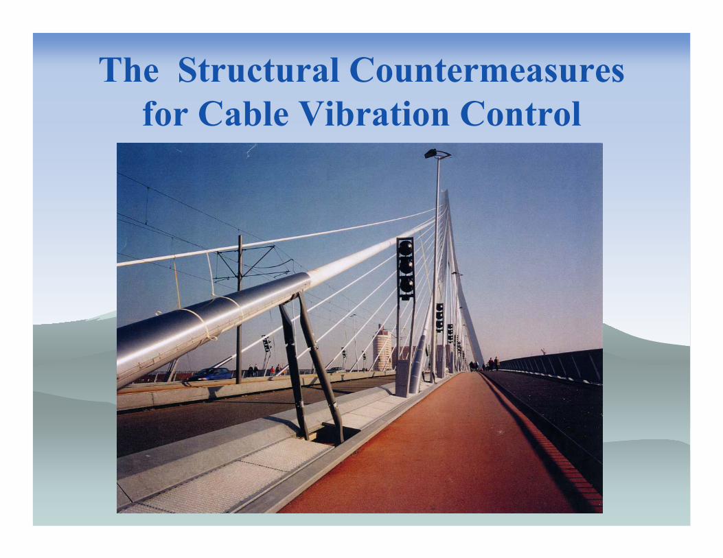
The Structural Countermeasures for Cable Vibration Control
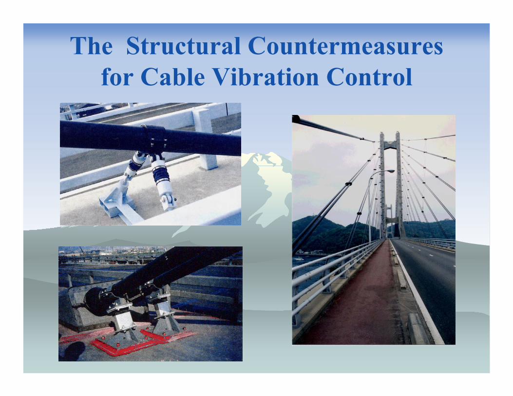
The Structural Countermeasures for Cable Vibration Control
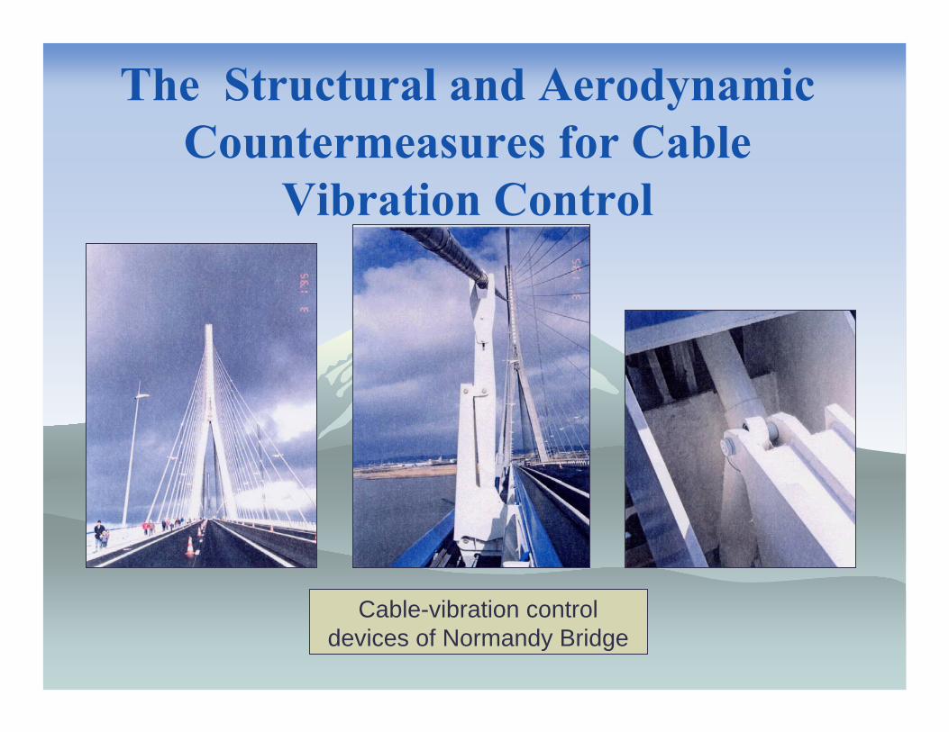
The Structural and Aerodynamic Countermeasures for Cable
Vibration Control
Cable-vibration control devices of Normandy Bridge
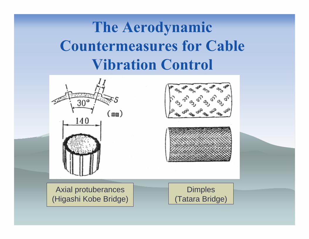
The Aerodynamic Countermeasures for Cable
Vibration Control
Axial protuberances(Higashi Kobe Bridge)
Dimples(Tatara Bridge)
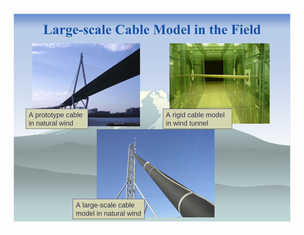
Large-scale Cable Model in the Field
A large-scale cable model in natural wind
A rigid cable model in wind tunnel
A prototype cable in natural wind
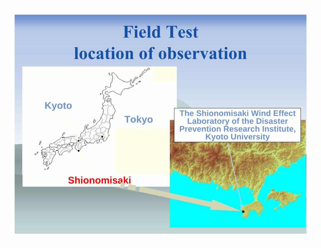
Field Testlocation of observation
Shionomisaki
KyotoTokyo The Shionomisaki Wind Effect
Laboratory of the Disaster Prevention Research Institute,
Kyoto University
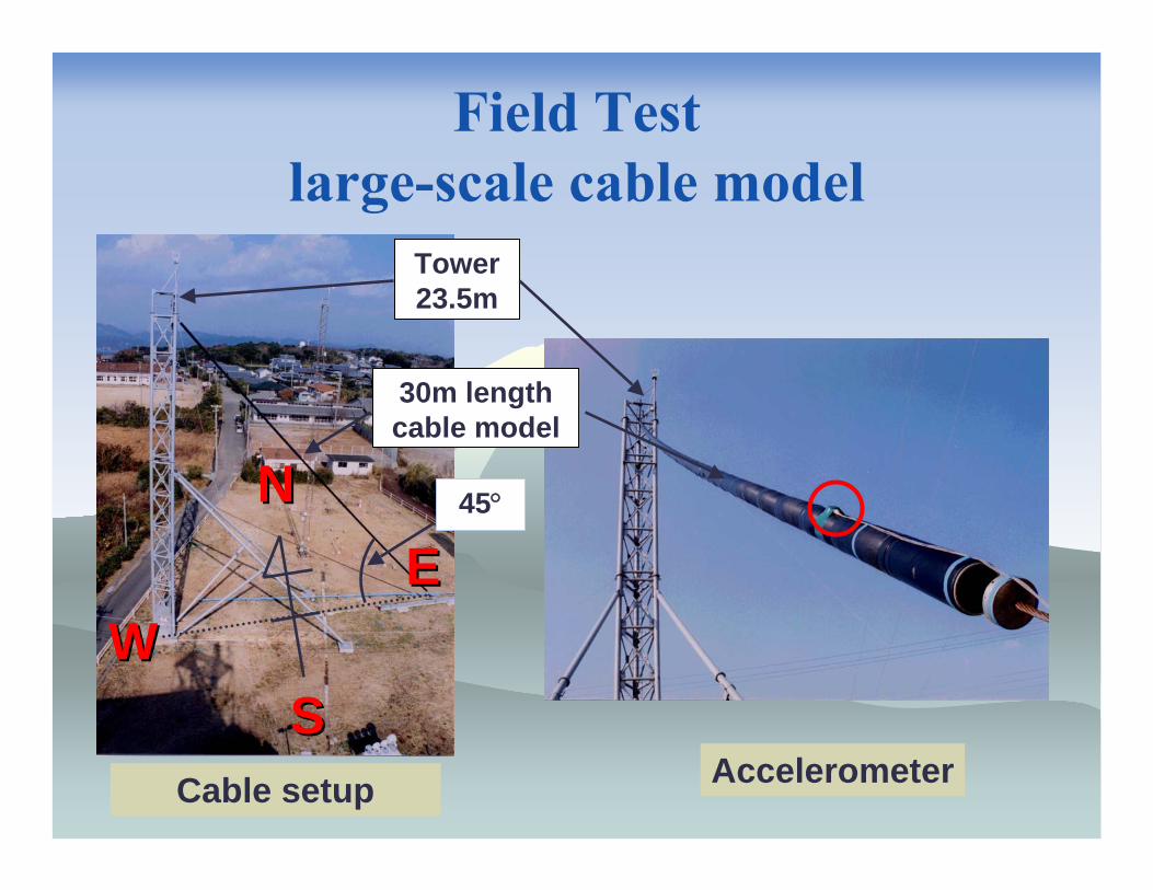
Field Testlarge-scale cable model
Tower23.5m
Cable setup
WW
NN
SS
EE
Accelerometer
30m lengthcable model
45°
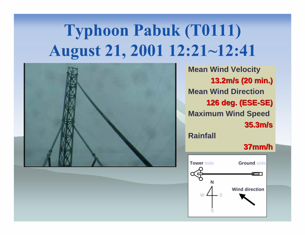
Typhoon Pabuk (T0111) August 21, 2001 12:21~12:41
Mean Wind Velocity13.2m/s (20 min.)13.2m/s (20 min.)
Mean Wind Direction126 deg. (ESE126 deg. (ESE--SE)SE)
Maximum Wind Speed35.3m/s35.3m/s
Rainfall37mm/h37mm/h
N
S
EWWind direction
Tower side Ground side

Power Spectrum of Acceleration & Displacement of First mode
0 5 10 15 200
1
2
3
4
Frequency [Hz]
P.S.
D. [
(m/s
2 )2 /Hz]
0 5 10 15 200
1
2
3
4
Frequency [Hz]
P.S.
D. [
(m/s
2 )2 /Hz]
0 200 400 600 800 1000 1200- 1
- 0.8- 0.6- 0.4- 0.2
00.20.40.60.8
1
Time [sec.]
Disp
lace
men
t [m
]
0 200 400 600 800 1000 1200- 1
- 0.8- 0.6- 0.4- 0.2
00.20.40.60.8
1
Time [sec.]
Disp
lace
men
t [m
]
Out Plane Acceleration In Plane Acceleration
In Plane Amplitude of First ModeOut Plane Amplitude of First Mode
First ModeV/fD≅120
1.36m
680 681 682 683 684 685 686 687 688 689 690- 1
- 0.8- 0.6- 0.4- 0.2
00.20.40.60.8
1O
ut-p
lane
dis
plac
emen
t [m
]
Time [sec]

600 650 700 750 8000
10
20
30
Time [sec]
Win
d ve
loci
ty [m
/s]
600 650 700 750 8000
30
60
90
Inte
nsity
[%]
Wind velocity and intensity
Wind velocity
Intensity
Max responseMax response
SummaryStay-cables can be easily excited by the cooperation of wind and rain or only wind, if certain conditions would be satisfied.
Periodical inspection of damping devices are definitely required.

Thank you very much for your kind attention.
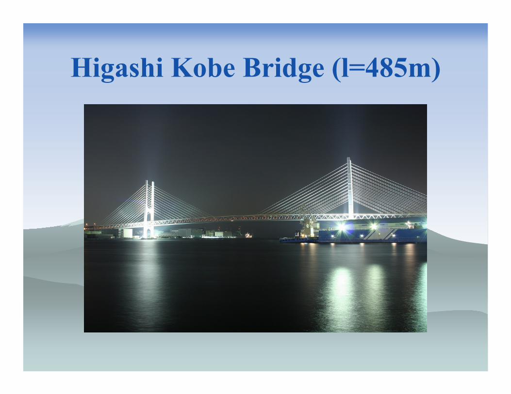
Higashi Kobe Bridge (l=485m)
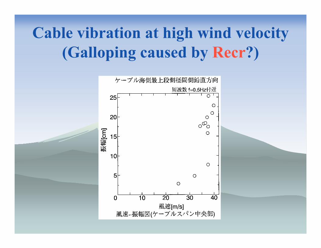
Cable vibration at high wind velocity(Galloping caused by Recr?)


![BRI-CABLE [Niels J. Gimsing] Cable Supported Bridges(1st)](https://static.fdocuments.net/doc/165x107/563db83b550346aa9a91c83b/bri-cable-niels-j-gimsing-cable-supported-bridges1st.jpg)


![[TECH]Cable Stayed Bridges](https://static.fdocuments.net/doc/165x107/544cd985b1af9f3a0b8b4c5b/techcable-stayed-bridges.jpg)