WinCC Flexible and TOP Server CE - ftp.softwaretoolbox.com · WinCC Flexible adds your first HMI...
25
WinCC Flexible and TOP Server CE Using on Siemens Panels
Transcript of WinCC Flexible and TOP Server CE - ftp.softwaretoolbox.com · WinCC Flexible adds your first HMI...

WinCC Flexible and TOP Server CE
Using on Siemens Panels

Page 2 of 25
Table of Contents
INTRODUCTION 3
INSTALLATION 4
CONFIGURING THE TOP SERVER 5
CONFIGURING THE WINCC FLEXIBLE PROJECT 7
Creating a WinCC Flexible Project 7
Configuring Connections 8
Configuring OPC Tags 9
Configuring an HMI Screen 13
TESTING THE WINCC FLEXIBLE RUNTIME 16
TRANSFERRING TOP SERVER 18
TRANSFERRING THE WINCC FLEXIBLE PROJECT 23
TROUBLESHOOTING TIPS 24
CONTACT US 25

Page 3 of 25
Introduction
This document covers the TOP Server for Siemens Panels in the examples and can be used as a guide for
any of the TOP Servers for Siemens Panels drivers. TOP Server for Siemens Panels currently works on
MP277, MP370 and MP377 panels, regardless of screen size.
Note: The server is not licensed on the desktop but on the panel only. We automatically create Icons for
licensing on the MP panels as part of the transfer process to the panel. Licensing is covered in detail in the
driver help file. You do not have to have a license in order to test the TOP server connection or do
configuration. This paper does not cover licensing.
Page 4 of 25
Installation
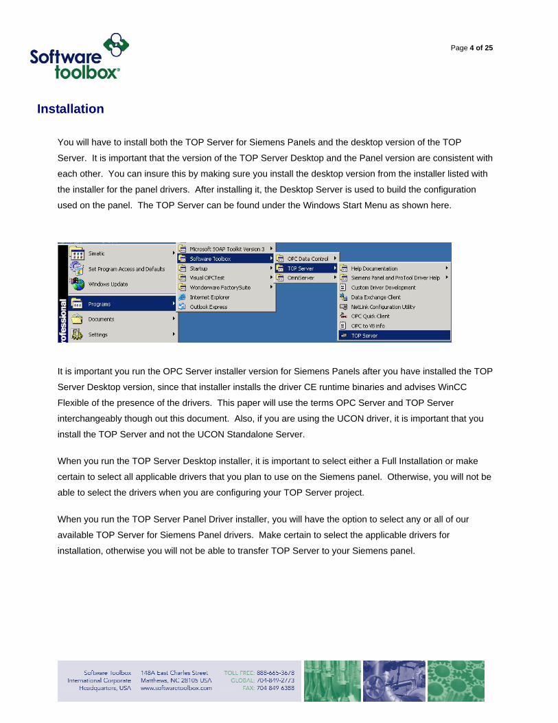
You will have to install both the TOP Server for Siemens Panels and the desktop version of the TOP
Server. It is important that the version of the TOP Server Desktop and the Panel version are consistent with
each other. You can insure this by making sure you install the desktop version from the installer listed with
the installer for the panel drivers. After installing it, the Desktop Server is used to build the configuration
used on the panel. The TOP Server can be found under the Windows Start Menu as shown here.
It is important you run the OPC Server installer version for Siemens Panels after you have installed the TOP
Server Desktop version, since that installer installs the driver CE runtime binaries and advises WinCC
Flexible of the presence of the drivers. This paper will use the terms OPC Server and TOP Server
interchangeably though out this document. Also, if you are using the UCON driver, it is important that you
install the TOP Server and not the UCON Standalone Server.
When you run the TOP Server Desktop installer, it is important to select either a Full Installation or make
certain to select all applicable drivers that you plan to use on the Siemens panel. Otherwise, you will not be
able to select the drivers when you are configuring your TOP Server project.
When you run the TOP Server Panel Driver installer, you will have the option to select any or all of our
available TOP Server for Siemens Panel drivers. Make certain to select the applicable drivers for
installation, otherwise you will not be able to transfer TOP Server to your Siemens panel.

Page 5 of 25
Configuring the TOP Server
When TOP Server opens it should open the sample project installed at the following location on your
computer:
C:\Program Files\Common Files\Siemens\PTProSave\AddOn\Software Toolbox\Common
You can get to it manually by opening an existing project and browsing to the same file location and
choosing: topserverwince.opf. This project can be modified to meet the needs of the particular project or a
new project can be opened. At a minimum the channel and device need to be configured. Tag
configuration in the server is recommended, but dynamic tags can be added from WinCC Flexible once the
device is fully configured in the OPC Server.
Configure the server with tags first and save this file with the name, “topserverwince.opf” to the path the
sample project was installed to as shown above. It is critical this file name and location is used. You can
save off back-up versions of this file to other locations.
If you need instructions on configuring the TOP Server please use this link, as this topic is outside the
scope of this paper:
http://www.toolboxopc.com/Support/More_Downloads/more_downloads.html
Help on using the UCON driver can be found at:
http://www.toolboxopc.com/ucon/QuickStart/quickstart.html

Page 6 of 25
Before starting configuration in WinCC Flexible, if you do not have active devices connected to the TOP
Server computer, make sure the devices in the OPC Server have the “Simulate Device” box check as
shown below.
If this isn’t done it will take a very long time to configure the project. It is also critical that the devices are
taken off Simulate I/O, by un-checking this box before downloading the project to the Panel. This is a
particular problem with Array tags. Siemens HMIs ask the OPC Server to verify the tag with the PLC on
each tag configuration. If you configure the project on the desktop OPC Server while it is not connected to
the PLC, we have to wait for a timeout, since the HMI wants us to verify each tag exists in the PLC before
moving on.
Page 7 of 25
Configuring the WinCC Flexible Project
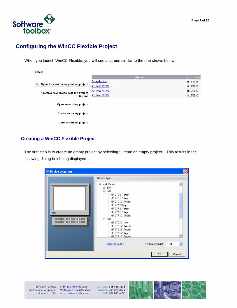
When you launch WinCC Flexible, you will see a screen similar to the one shown below.
Creating a WinCC Flexible Project
The first step is to create an empty project by selecting “Create an empty project”. This results in the
following dialog box being displayed.
Page 8 of 25
Make sure to select the proper device type from the list of Siemens panels prior to clicking OK. The project
must use an MP277, MP370 or MP377 device type to work with TOP Server.
Configuring Connections
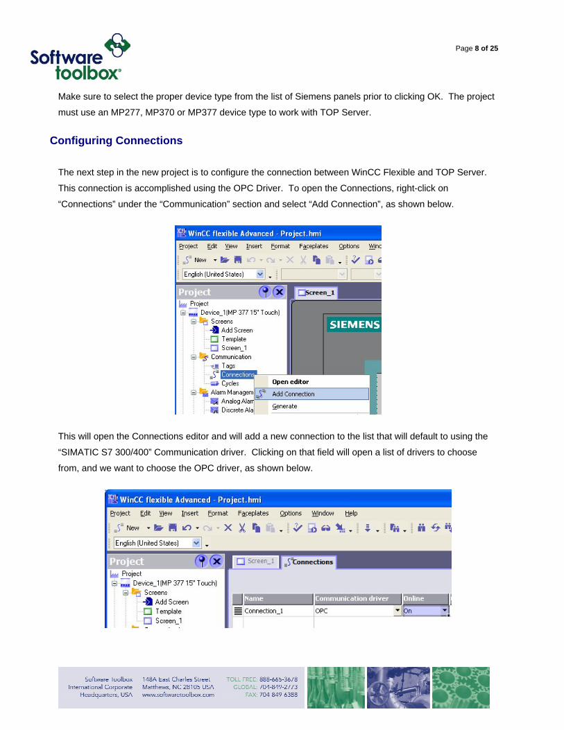
The next step in the new project is to configure the connection between WinCC Flexible and TOP Server.
This connection is accomplished using the OPC Driver. To open the Connections, right-click on
“Connections” under the “Communication” section and select “Add Connection”, as shown below.
This will open the Connections editor and will add a new connection to the list that will default to using the
“SIMATIC S7 300/400” Communication driver. Clicking on that field will open a list of drivers to choose
from, and we want to choose the OPC driver, as shown below.

Page 9 of 25
This opens the “Device OPC Server” section at the bottom of the interface, as shown below.
This section allows you to browse for all OPC Servers on your local or remote machines. We are only
interested in the TOP Server on the local machine, so we find the ProgID for TOP Server in the list of
servers, “SWToolbox.TOPServer” and select it.
Configuring OPC Tags
The next step is to create tags for the addresses you want to access in your device. We recommend creating tags in the TOP Server configuration, since it is easier in most cases than doing dynamic tags in WinCC Flexible. However, it is possible to do dynamic tags by entering a fully qualified OPC path.
Example: ChannelName.DeviceName.TagAddress@datatype
A dynamic tag going to the Channel and Device shown in the picture below would use the syntax Enet.TI505.V10@Word for example.
An Array tag for the Simatic 505 Ethernet driver in this example would look like: Enet.TI505.V10[10]@Word
The Tag Address is dependent on the particular driver being used. See the Addressing under the TOP
Server driver help file for the specific driver you are using for more details. More information on dynamic
Page 10 of 25
tags including possible data types can be found in the TOP Server Help file under Basic Server
Components – What is a Tag? – Tag Properties – Dynamic Tags.
From the Help file:
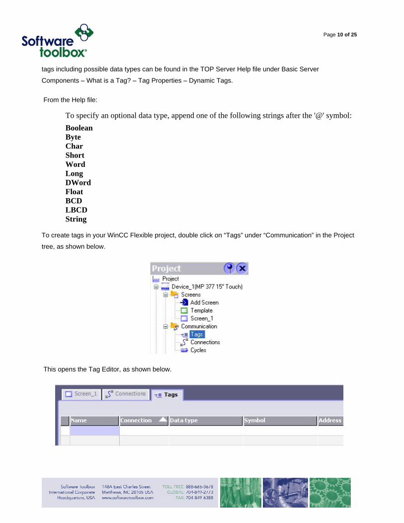
To specify an optional data type, append one of the following strings after the '@' symbol: Boolean Byte Char Short Word Long DWord Float BCD LBCD String
To create tags in your WinCC Flexible project, double click on “Tags” under “Communication” in the Project
tree, as shown below.
This opens the Tag Editor, as shown below.
Page 11 of 25
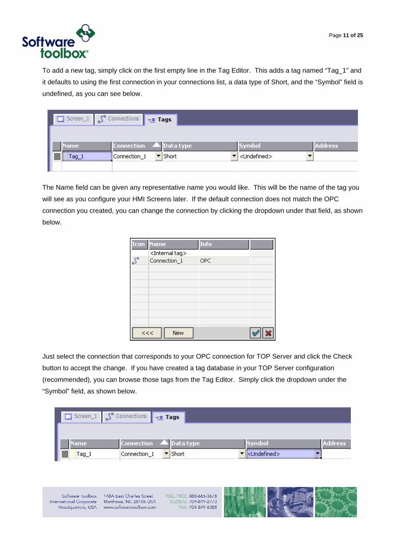
To add a new tag, simply click on the first empty line in the Tag Editor. This adds a tag named “Tag_1” and
it defaults to using the first connection in your connections list, a data type of Short, and the “Symbol” field is
undefined, as you can see below.
The Name field can be given any representative name you would like. This will be the name of the tag you
will see as you configure your HMI Screens later. If the default connection does not match the OPC
connection you created, you can change the connection by clicking the dropdown under that field, as shown
below.
Just select the connection that corresponds to your OPC connection for TOP Server and click the Check
button to accept the change. If you have created a tag database in your TOP Server configuration
(recommended), you can browse those tags from the Tag Editor. Simply click the dropdown under the
“Symbol” field, as shown below.

Page 12 of 25
This opens the tag browser, which connects to and displays the tag address space of the OPC Server
defined in your connection, which is TOP Server. If this takes a long time, make sure the server is open
and devices are in I/O mode as discussed previously.
The tree structure allows you to expand your TOP Server channels and, by highlighting the underlying
devices, displays the tags you have configured, as you can see below.
To select a tag, simply highlight it and click the Check button at the bottom of the browser. This fills the
Symbol and Address fields with the proper fully qualified OPC item name, as well as changing the Data type
to match that of the tag in TOP Server, as shown below.
This is all that is required if you are reading a non-array tag. When configuring an Array Tag, the next step
is to choose which element in the array tag in the OPC Server is connected to this particular tag in WinCC
Flexible. The 6th element is selected in the example shown below. Arrays in the PLC begin with zero, so
this corresponds to MyArray[5].
Page 13 of 25
Configuring an HMI Screen
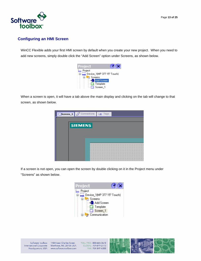
WinCC Flexible adds your first HMI screen by default when you create your new project. When you need to
add new screens, simply double click the “Add Screen” option under Screens, as shown below.
When a screen is open, it will have a tab above the main display and clicking on the tab will change to that
screen, as shown below.
If a screen is not open, you can open the screen by double clicking on it in the Project menu under
“Screens” as shown below.
Page 14 of 25
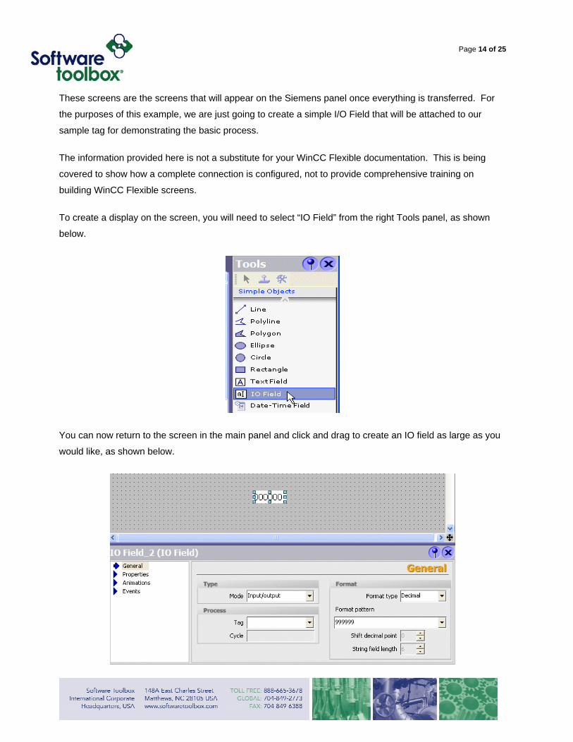
These screens are the screens that will appear on the Siemens panel once everything is transferred. For
the purposes of this example, we are just going to create a simple I/O Field that will be attached to our
sample tag for demonstrating the basic process.
The information provided here is not a substitute for your WinCC Flexible documentation. This is being
covered to show how a complete connection is configured, not to provide comprehensive training on
building WinCC Flexible screens.
To create a display on the screen, you will need to select “IO Field” from the right Tools panel, as shown
below.
You can now return to the screen in the main panel and click and drag to create an IO field as large as you
would like, as shown below.
Page 15 of 25
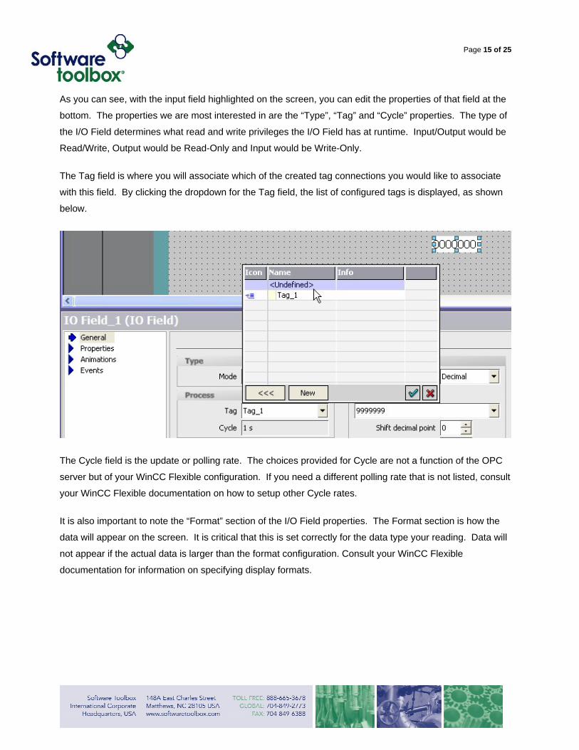
As you can see, with the input field highlighted on the screen, you can edit the properties of that field at the
bottom. The properties we are most interested in are the “Type”, “Tag” and “Cycle” properties. The type of
the I/O Field determines what read and write privileges the I/O Field has at runtime. Input/Output would be
Read/Write, Output would be Read-Only and Input would be Write-Only.
The Tag field is where you will associate which of the created tag connections you would like to associate
with this field. By clicking the dropdown for the Tag field, the list of configured tags is displayed, as shown
below.
The Cycle field is the update or polling rate. The choices provided for Cycle are not a function of the OPC
server but of your WinCC Flexible configuration. If you need a different polling rate that is not listed, consult
your WinCC Flexible documentation on how to setup other Cycle rates.
It is also important to note the “Format” section of the I/O Field properties. The Format section is how the
data will appear on the screen. It is critical that this is set correctly for the data type your reading. Data will
not appear if the actual data is larger than the format configuration. Consult your WinCC Flexible
documentation for information on specifying display formats.
Page 16 of 25
Testing the WinCC Flexible Runtime
Once your TOP Server configuration is complete and you have configured your WinCC Flexible project, it is
always recommended to test your configuration on the configuration PC if at all possible. This may or may
not be possible depending on your device network and the availability of connecting the PC to that network.
If possible, it is definitely worthwhile to perform this test to ensure that your configuration is correct prior to
transferring both the TOP Server and your WinCC Flexible project to the destination Siemens panel.
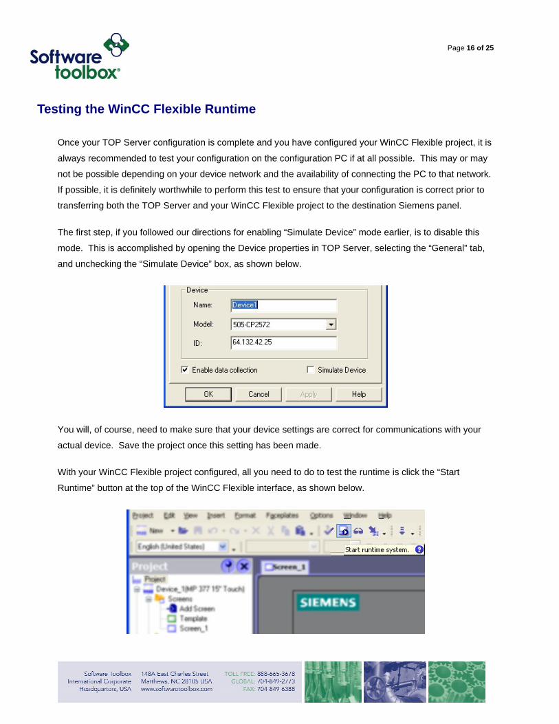
The first step, if you followed our directions for enabling “Simulate Device” mode earlier, is to disable this
mode. This is accomplished by opening the Device properties in TOP Server, selecting the “General” tab,
and unchecking the “Simulate Device” box, as shown below.
You will, of course, need to make sure that your device settings are correct for communications with your
actual device. Save the project once this setting has been made.
With your WinCC Flexible project configured, all you need to do to test the runtime is click the “Start
Runtime” button at the top of the WinCC Flexible interface, as shown below.

Page 17 of 25
If you have not recently saved your WinCC Flexible project, you will be prompted to do so. WinCC Flexible
will then compile your project and launch the runtime, displaying the first screen in your project. You should
see correct values for all of your fields in this runtime if everything is configured correctly and your machine
is connected to your device properly, as shown below for our example.
If this is not the case, and you know that you should have no physical connectivity issues from this PC to
your devices, then there is a configuration issue in either your WinCC Flexible application or your TOP
Server configuration file. You can contact our technical support team via the contact information at the end
of this document for assistance in troubleshooting your communications.
Given that you are seeing expected behavior with your runtime, the next step is to transfer the TOP Server
and your WinCC Flexible project to your Siemens panel.

Page 18 of 25
Transferring TOP Server
This step can be done before a project is complete, if desired, but a project has to at least be started for the
particular Panel type and the Connection configured before the OPC Server can be transferred to the
Panel. Before you can transfer the OPC Server you have to configure an Ethernet connection to the Panel
in WinCC Flexible.
In WinCC Flexible, under the Project menu, select Transfer then Transfer Settings, as shown below.
This opens the Transfer Settings dialog box, where you will select your mode of connection to the Panel
and input the correct communications settings.

Page 19 of 25
The most common method for connecting to the panel is via Ethernet, which is what is used in this
example, as shown below.
Once all these settings are correct click Apply. Do not click the Transfer button until you are ready to
transfer the WinCC Flexible project to the panel. This dialog will close after you click any of the buttons.
(It is important to note that your Ethernet connection must be configured properly for the network card on the Siemens panel, as well. You must ensure that a valid IP Address is assigned to the Siemens panel, and also that the correct Subnet Mask and Gateway IP Address are configured. Otherwise, communications on the Siemens panel may not be successful.)
Now, open the Project menu again, select Transfer and then Options, as shown below.
This will open the ProSave dialog box, which allows you to browse your computer for files to transfer to your
Siemens panel (separate from your WinCC Flexible HMI project).

Page 20 of 25
If the browse location does not default to the TOP Server for Siemens Panels installation directory
(C:\Program Files\Common Files\Siemens\PTProSave\AddOn\Software Toolbox), you will need to
click the (…) Ellipses button, then browse and select the correct path, as shown below.
When the correct path is selected, available options will be listed, which will depend on which TOP Server
drivers for Siemens panels you have installed. For this example, only a single driver was installed, so there
will be two options available: the actual TOP Server Driver/Server and the Config File Update.
For every TOP Server driver you want installed on a given Siemens panel, you will need to perform this
transfer process. Prior to any transfer, you must make sure to click the “Transfer” button on the Loader
menu on the Siemens panel. After this, click on the Device status button. If no error happens you have a
good connection. (If other TOP Server drivers are installed on the panel, they will appear in the “Installed
options” list after a Status check.)

Page 21 of 25
Next highlight the OPC Server driver you want to download. The names for all TOP Server OPC Servers in
this list will include the driver name and panel type. Click on the >> button to initiate the transfer, as shown
below. Note: Selecting the OPC Server driver option for transfer also transfers the relevant TOP Server configuration files.
The transfer process will begin and you will see a progress dialog box. After completion, a message telling
you the downloaded completed will display, as shown below.
On the Siemens panel, you will be prompted to reboot the panel, which will finish the installation process.
The other available option for install, TOP Server Config File Update, in the ProSave list is only for
updating the TOP Server configuration file when and if you have made changes to your TOP Server project,
and should be used if you have already transferred the TOP Server driver to the panel and need to update
the project file.
For a configuration file update to be successful the WinCC project can’t be running on the Panel and the
OPC Test applications must all be shut down on the Panel, with the Transfer button in the Loader menu
pressed. If you cycle power on the panel after downloading the configuration, it will insure that the new

Page 22 of 25
OPC Server project is used by the server. It is critical that the OPC project you create on the desktop for
download is saved under the correct name and saved to the correct path.
Once the transfer is complete you can test the configuration and connection to devices using the OPC
Quick Client Icon that is installed on the Panel.
There is also an Icon for the license utility installed for licensing the product. Licensing of the driver on the
panel is also covered in the TOP Server CE help file version installed by the Siemens Panel version
installer.
Page 23 of 25
Transferring the WinCC Flexible Project
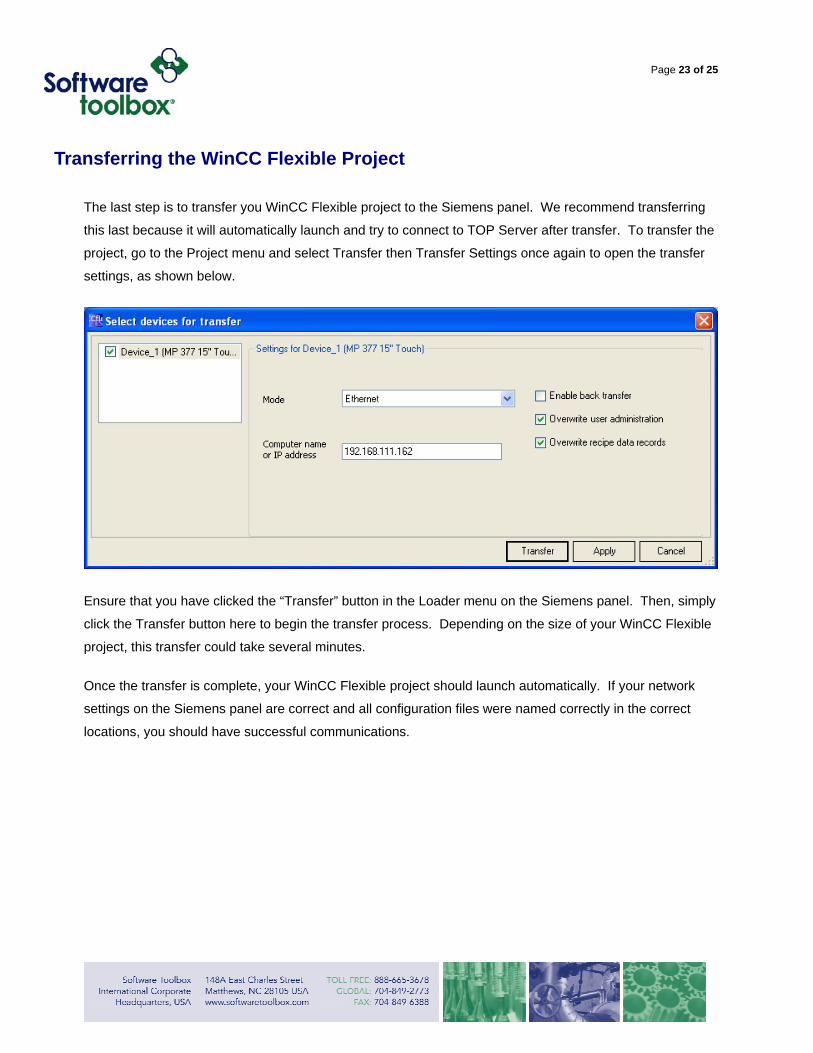
The last step is to transfer you WinCC Flexible project to the Siemens panel. We recommend transferring
this last because it will automatically launch and try to connect to TOP Server after transfer. To transfer the
project, go to the Project menu and select Transfer then Transfer Settings once again to open the transfer
settings, as shown below.
Ensure that you have clicked the “Transfer” button in the Loader menu on the Siemens panel. Then, simply
click the Transfer button here to begin the transfer process. Depending on the size of your WinCC Flexible
project, this transfer could take several minutes.
Once the transfer is complete, your WinCC Flexible project should launch automatically. If your network
settings on the Siemens panel are correct and all configuration files were named correctly in the correct
locations, you should have successful communications.

Page 24 of 25
Troubleshooting Tips
1. If you cannot successfully transfer to the panel, make sure you can Ping the IP address of the Panel
from the PC. You can also launch a command prompt from the Start menu and ping from the Siemens
panel.
2. If you get bad quality data:
• Try transferring the whole OPC server onto the Panel again.
• Verify the configuration with the OPC Quick Client through browsing.
• If this is Ethernet communications, verify that the Network Card on the Siemens panel has a valid
Subnet Mask and Gateway IP Address configured for communications with your devices on the
network.

Page 25 of 25
Contact Us
If you have any questions or are seeking further information and help:
Online Support: http://support.softwaretoolbox.com/
Email Support: [email protected]
Phone Support: +1 (704) 849-2773
Fax: +1 (704) 849-6388
Mailing Address: Software Toolbox, Inc. 148A East Charles Street, Matthews, NC, 28105 USA