WILSON AUDIO SPECIALTIES, INC. audio specialties, inc. table of graphics iii figure 1- woofer,...
80
Transcript of WILSON AUDIO SPECIALTIES, INC. audio specialties, inc. table of graphics iii figure 1- woofer,...


W I L S O N A U D I O S P E C I A L T I E S , I N C .

W I L S O N A U D I O S P E C I A L T I E S , I N C .
WILSON AUDIO SPECIALTIES
X-1/GRANDSLAMM OWNER’S MANUAL

W I L S O N A U D I O S P E C I A L T I E S , I N C .
Wilson Audio is a registered trademark of Wilson Audio Specialties Inc.
X-1/Grand Slamm is a registered trademark of Wilson Audio Specialties Inc.
This manual was produced by the Wilson Audio Engineering Department in cooperation with Sales and Marketing. The infor-
mation contained here in is subject to change without notice. Current Revision 2.0, Feb. 2000 if you are in need of a more recent
manual please contact your dealer.

W I L S O N A U D I O S P E C I A L T I E S , I N C . i
T A B L E O F C O N T E N T S
TABLE OF GRAPHICS ............................................................................................................................................III
COMPONENTS AND DIMENSIONS ............................................................................................................................................. IV
SECTION 1.0- ROOM ACOUSTICS ........................................................................................................................... 1-1
FINAL LISTENING ROOM SETUP (VOICING) ............................................................................................................................. 1-1
SECTION 1.1-ROOM REFLECTIONS ....................................................................................................................... 1-2
SLAP-ECHO .......................................................................................................................................................................... 1-2STANDING WAVES ................................................................................................................................................................. 1-3COMB FILTER EFFECT ............................................................................................................................................................ 1-4
SECTION 1.2-RESONANCE’S .................................................................................................................................... 1-5
STRUCTURAL RESONANCE ..................................................................................................................................................... 1-5AIR VOLUME RESONANCE .................................................................................................................................................... 1-5
SECTION 1.3-IN YOUR ROOM .................................................................................................................................. 1-6
ROOM SHAPES ..................................................................................................................................................................... 1-6SPEAKER PLACEMENT VS. LISTENING POSITION ....................................................................................................................... 1-7CHOOSING A LISTENING POSITION ......................................................................................................................................... 1-7SPEAKER ORIENTATION ......................................................................................................................................................... 1-8SUMMARY ............................................................................................................................................................................ 1-9
SECTION 2.0-CARE OF THE X-1/GRAND SLAMM ............................................................................................... 2-1
PAINTED OR WOOD FINISH .................................................................................................................................................... 2-1BREAK IN PERIOD ................................................................................................................................................................ 2-2
SECTION 2.1 ENCLOSURE CONSTRUCTION ....................................................................................................... 2-2
MATERIAL ........................................................................................................................................................................... 2-2ADHESIVE ............................................................................................................................................................................ 2-3DEPTH OF DESIGN ................................................................................................................................................................ 2-3CONLCUSION ........................................................................................................................................................................ 2-3
SECTION 3.0-UNCRATING THE X-1/GRAND SLAMM ........................................................................................ 3-1
INITIAL CHECK ..................................................................................................................................................................... 3-1UNCRATING THE WOOFER CABINETS ...................................................................................................................................... 3-1MATERIALS REQUIRED .......................................................................................................................................................... 3-1UNPACKING THE WOOFER ..................................................................................................................................................... 3-1UNCRATING THE FASCIA ASSEMBLY ....................................................................................................................................... 3-2UNCRATING THE UPPER ARRAY MODULES .............................................................................................................................. 3-2CRATE CONTENTS: CHECKLIST .............................................................................................................................................. 3-4ASSEMBLE YOUR SPIKES FOLLOWING THESE STEPS: .................................................................................................................. 3-5
SECTION 4.0- X-1/GRANDSLAMM INITIAL ASSEMBLY .................................................................................... 4-1
TIMING BLADES ................................................................................................................................................................... 4-1CONNECT THE TIMING BLADES TO THE WOOFER CABINET AS FOLLOWS: ..................................................................................... 4-2

W I L S O N A U D I O S P E C I A L T I E S , I N C .
M A X X O W N E R ’ S M A N U A L
ii
TABLE OF CONTENTS CONT.
SECTION 4.1-MOUNTING THE UPPER ARRAY MODULES ......................................................................... 4-3
MATERIALS REQUIRED .................................................................................................................................................... 4-3MOUNTING PROCEDURE .................................................................................................................................................. 4-3MOUNTING THE UPPER CROSSOVER ................................................................................................................................. 4-5CONNECTING THE UPPER RANGE SIGNAL CABLE .............................................................................................................. 4-7CONNECTOR PLATE JUMPER ............................................................................................................................................ 4-8
SECTION 4.2- GEOMETRIC TIME DOMAIN ALIGNMENT ......................................................................... 4-9
MATERIALS REQUIRED .................................................................................................................................................... 4-9PULSE ALIGNMENT ......................................................................................................................................................... 4-9ROOM SETUP ................................................................................................................................................................. 4-9ALIGNMENT PROCEDURE ............................................................................................................................................... 4-10
SECTION 4.3- TIME ALIGNMENT EXAMPLE ............................................................................................... 4-12
GIVEN: ........................................................................................................................................................................ 4-12
SECTION 4.4- LOCKING DOWN UPPER ARRAY .......................................................................................... 4-14
MATERIALS REQUIRED .................................................................................................................................................. 4-14LOCKING DOWN THE UPPER ARRAY ............................................................................................................................... 4-14
SECTION 4.5- SPIKE INSTALLATION ............................................................................................................. 4-15
MATERIALS REQUIRED .................................................................................................................................................. 4-15INSTALLATION PROCEDURE ............................................................................................................................................ 4-15LEVELING THE X-1 GRAND SLAMM ............................................................................................................................... 4-18
SECTION 4.6-CHECKING THE IMAGE HEIGHT ......................................................................................... 4-19
SECTION 4.7-ATTACHING THE FASCIA’S ..................................................................................................... 4-20
REQUIRED MATERIALS: ................................................................................................................................................. 4-20ATTACHMENT PROCEDURE: ........................................................................................................................................... 4-20
SECTION-5.0 WARRANTY INFORMATION ..................................................................................................... 5-1
SECTION 6.0 SETTING UP DIFFICULTIES AND TROUBLESHOOTING ................................................... 6-1
SECTION 7.0- SPECIFICATIONS ........................................................................................................................ 7-1
APPENDIX A- TIMING CHARTS ........................................................................................................................ A-1

W I L S O N A U D I O S P E C I A L T I E S , I N C .
T A B L E O F G R A P H I C S
iii
FIGURE 1- WOOFER, STAND, AND MAIN CROSSOVER ........................................................................................... 3-1FIGURE 2- TIMING BLADE AND FASCIA ............................................................................................................... 3-2FIGURE 3- UPPER ARRAY MODULES ................................................................................................................... 3-3FIGURE 4- UPPER ARRAY MODULES ................................................................................................................... 3-3FIGURE 5- UPPER ARRAY MODULES ................................................................................................................... 3-3FIGURE 6- UPPER CROSSOVER ............................................................................................................................ 3-3FIGURE 7- TILTING POLES .................................................................................................................................. 3-3FIGURE 8- X-1 SPIKES ...................................................................................................................................... 3-5FIGURE 9- NUMBER LOCATIONS ON FASCIA ......................................................................................................... 4-1FIGURE 10- EXPLODED VIEW OF FASCIA ............................................................................................................. 4-1FIGURE 11- ATTACHING THE TIMING BLADE TO WOOFER ..................................................................................... 4-2FIGURE 12- UPPER BOLT ASSEMBLY ................................................................................................................... 4-3FIGURE 13- INSTALLING THE UPPER ARRAY ........................................................................................................ 4-3FIGURE 14- INSTALLED UPPER ARRAY MODULES. ............................................................................................... 4-4FIGURE 15- TIGHTENING THE UPPER ARRAY BOLT ............................................................................................... 4-4FIGURE 16- INSTALLING THE UPPER CROSSOVER.. ............................................................................................... 4-5FIGURE 17- POSITIONING THE UPPER CROSSOVER ................................................................................................ 4-5FIGURE 18- WIRING THE UPPER ARRAY .............................................................................................................. 4-6FIGURE 19- MAIN CONNECTOR PLATE ................................................................................................................ 4-7FIGURE 20- LISTENING DISTANCE AND EAR HEIGHT ............................................................................................ 4-9FIGURE 21- READING THE MARKINGS ON THE TIMING BLADE ............................................................................ 4-11FIGURE 22- LMRM ALIGNMENT CHART .......................................................................................................... 4-13FIGURE 23- TIGHTENING THE UPPER ARRAY BOLTS ........................................................................................... 4-14FIGURE 24- HOLE COVER LOCATIONS ON BASE/STAND ...................................................................................... 4-15FIGURE 25- TILTING THE X-1 FOR SPIKE INSTALLATION ..................................................................................... 4-15FIGURE 26- INSTALLING THE SPIKES. ................................................................................................................ 4-16FIGURE 27- SPIKES INSTALLED FIRST SIDE ........................................................................................................ 4-16FIGURE 28- INSTALLING SPIKES SECOND SIDE ................................................................................................... 4-17FIGURE 29- FASCIA BOLT LOCATIONS ............................................................................................................... 4-20FIGURE 30- FINISHED UPPER ARRAY ................................................................................................................ 4-20
TABLE OF GRAPHICS

W I L S O N A U D I O S P E C I A L T I E S , I N C . iv
X-1/ GRAND SLAMM - COMPONENTS AND DIMENSIONS
UPPER MID-FRE-QUENCY
MODULE
FASCIA ASSEMBLY
LOWER MID- FRE-QUENCY MODULE
HIGH FREQUENCY MODULE
UPPER ARRAY CROSSOVER
WOOFER ENCLO-SURE
STAND/BASE
ENCLOSURE
15.25 IN.39 CM
9 IN.23 CM
16.5 IN.42 CM
25.25 IN.64 CM
72 IN.183 CM
UPPER ARRAY CROSSOVER

W I L S O N A U D I O S P E C I A L T I E S , I N C .


1R O O M A C O U S T I C S

W I L S O N A U D I O S P E C I A L T I E S , I N C .

W I L S O N A U D I O S P E C I A L T I E S , I N C .
S e c t i o n 1 - R o o m A c o u s t i c s
You are surely excited about setting up your X-1/GrandSLAMM loudspeakers and doing some lis-
tening, but before you begin we would like to discuss some of the important room acoustical information
that will help you set up your loudspeakers properly.
FINAL LISTENING ROOM SETUP (VOICING)
Your X-1/GrandSLAMM loudspeakers will give you years of music satisfaction. However, their
high performance characteristics and abilities can only be fully appreciated with the proper acoustical setup.
The following section will present some guidelines on room acoustics and their interactions with
loudspeakers. We will also offer some detailed suggestions on the setup of the X-1/GrandSLAMMs, but
we strongly suggest that you have your local Wilson Audio dealer perform the final speaker “voicing” for
you. They are specially trained in setting up Wilson loudspeakers and will ensure that you realize the full
value of your purchase.
1-1
SECTION 1.0 ROOM ACOUSTICS

W I L S O N A U D I O S P E C I A L T I E S , I N C .
SECTION 1.1 ROOM REFLECTIONS
There are 3 commonly encountered room reflection problems: slap echoʼs, standing-
waves, and comb filter effect.
SLAP ECHO
Probably the most obnoxious form of reflection is called “slap echo.” With slap echo, primarily mid-
range and high frequency sounds reflect off of two parallel hard surfaces. The sound literally reverberates
back and forth until it is finally dissipated over time. You can test for slap echo in any room by clapping
your hands sharply in the middle of the room and listening for the characteristic sound of the echo in the
mid-range. Slap echo destroys the sound quality of a stereo system in two ways:
§ It adds harshness to the upper mid-range and treble through energy time storage.
§ It destroys the delicate phase relationships, which help to establish an accurate sound stage.
Slap echo is a common acoustical problem in the typical domestic listening room because most of
these rooms have walls with a hard, reflective nature, usually being only occasionally interrupted by curtains
or drapes. The best solution to eliminate slap echo is non-parallel walls, this is because non-parallel walls do
not support slap echo, but rather allow the sound to diffuse. Otherwise, slap echo can be controlled entirely
by the application of absorptive materials to the hard surfaces, such as:
§ Sonex
§ Airduct board
§ Cork panels to the hard surfaces.
§ Large ceiling to floor drapes
§ Carpeting to wall surfaces.
In many domestic listening environments, heavy stuffed furnishings are the primary structural con-
trol to slap echo. Unfortunately, their effectiveness is not predictable. Diffusers are
1-2
X-1/ GRAND SLAMM OWNER’S MANUAL

W I L S O N A U D I O S P E C I A L T I E S , I N C .
sometimes also used to very good subjective effect, particularly in quite large rooms. Sound absorbent ma-
terials such as described above will alter the tonal characteristic of the room by making it sound “deader,”
less “bright and alive” and “quieter.” These changes also make the room more pleasant for conversation.
Diffusers, on the other hand, tend to not change the tonal balance characteristic of the room, but make the
sound smoother and more open.
STANDING WAVES
Another type of reflection phenomenon is “standing waves.” Standing waves cause the unnatural
boosting or accentuation of certain frequencies, typically in the bass, to be found at certain discreet locations
on the room. A room generating severe standing waves will tend to make a loudspeaker sound one way
when placed in one location and entirely different when placed in another. The effects of standing waves on
a loudspeaker’s performance primarily as follows:
§ Tonal balance
§ Resolution of low-level detail
§ Sound-staging
Standing waves are more difficult to correct than slap echo because they tend to occur at a lower
frequency, whose wavelength is long enough to be ineffectively controlled by absorbent materials such as
Sonex. Moving speakers about slightly in the room is, for most people, their only control over standing
waves. Sometimes a change of placement of as little as two or three inches can dramatically alter the tonal
balance of a small system. Fortunately, minor low frequency standing waves are well controlled by posi-
tioning ASC tube traps in the corners of the room. Very serious low frequency accentuation usually requires
a custom-designed bass trap system.
Low frequency standing waves can be particularly troublesome in rooms constructed of concrete or
brick. These materials trap the bass in the room, unless it is allowed to leak out of the room, through win-
dows and doors.
S E C T I O N 1 . 1 - R O O M R E F L E C T I O N S
1-3
X-1/ GRAND SLAMM OWNER’S MANUAL

W I L S O N A U D I O S P E C I A L T I E S , I N C .
In general, placement of the speaker in a corner will excite the maximal number of standing waves
in a room, and is to be avoided for most direct radiator, full range loudspeaker systems. Some benefit is
achieved by placing the stereo pair of loudspeakers slightly asymmetrically in the listening room. This is so
that the standing waves caused by the distance between one speaker, its adjacent walls and floors are not the
same as the standing wave frequencies excited by the dimensions in the other channel.
COMB FILTER EFFECT
The comb filter effect is a special type of standing wave noticeable primarily at higher frequencies
and shorter wavelengths.
Acoustical comb filtering occurs when sound from a single source, such as a loudspeaker, is di-
rected toward a microphone or listener from a distance. The first sound to reach the microphone is the
direct sound, followed by a delayed, reflected sound. At certain frequencies cancellation occurs, because
the reflected sound lags in phase relative to the direct sound. This cancellation is most apparent where the
two are 180 degrees out of phase. Further, there is augmentation at other frequencies where the direct and
the reflected sounds arrive in phase. Because it is a function of wavelength, the comb filter effect will notch
out portions of the audio spectrum at regular octave-spaced intervals. The subjective effect of comb filter
effects is as follows:
§ Added roughness to the sound
§ Reduction of harmonic richness
§ Smearing of lateral sound stage image focus and placement
Comb filter effects are caused by side wall reflections. These are best controlled by careful speaker
placement and by the placement of Sonex or air duct panels to the part of the wall where the reflection oc-
curs.
1-4
X-1/ GRAND SLAMM OWNER’S MANUAL

W I L S O N A U D I O S P E C I A L T I E S , I N C .
Resonance in listening rooms is generally caused by two sources:
§ Structures within the listening room
§ The volume of the air itself in the listening room
STRUCTURAL RESONANCE
Structural resonance’s are familiar to most people as buzzes and rattles, but this type of resonance
usually only occurs at extremely high volume levels, and is usually masked by the music. In many wood
frame rooms the most common type of structural resonance problem is “booming” of walls and floors. You
can test for these very easily by tapping the wall with the palm of your hand or stomping on the floor. To
give you an idea of what the perfect wall would sound like, imagine rapping your hand against the side of
a mountain. Structural wall resonance’s generally occur in the low to mid-bass frequencies and add tonal
balance fullness to any system played in that room. They too are more prominent at louder levels, but
their contribution to the sound of the speaker is more progressive. Rattling windows, picture frames, lamp
shades, etc. can generally be silenced with small pieces of caulk or with blocks of felt. However, short of
actually adding additional layers of sheet rock to flimsy walls, there is little that can be done to eliminate
wall resonance’s.
AIR VOLUME RESONANCE
The volume of air in a room will also resonate at a frequency determined by the size of the
room. Larger rooms will resonate at a lower frequency than will smaller rooms. Air volume res-
onanceʼs, wall panel resonanceʼs, and low frequency standing waves, together, combine to form
a low frequency coloration in the sound. At its worst, it is a grossly exaggerated fullness, which
tends to obscure detail and distort the natural tonal balance of the speaker system.
S E C T I O N 1 . 2 - RESONANCE’S
SECTION 1.2 RESONANCE’S
1-5
X-1/ GRAND SLAMM OWNER’S MANUAL

W I L S O N A U D I O S P E C I A L T I E S , I N C .
Occasionally, however, there is just enough resonance to give a little added warmth to the sound… an addi-
tion some listeners prefer. Tube traps manufactured by the ASC Corporation are effective in reducing some
of this low frequency room coloration. While, custom designed bass traps, such as perforated Helmholtz
resonators, provide the greatest degree of low frequency control.
SECTION 1.3- IN YOUR ROOM
ROOM SHAPES
There are three basic shapes for most rooms: square, rectangular, and L-shaped. A perfectly square
room is the most difficult room to set up speakers in because, by virtue of its shape, square rooms are the
perfect medium for building and sustaining standing waves. Standing waves are pressure waves created by
the integration of sound and opposing, parallel walls which accentuate particular frequencies. They heavily
influence the music played by loudspeakers, greatly diminishing the listening experience.
Long, narrow rectangular rooms also pose their own special acoustical problems for speaker setup.
They have the ability to set up several standing wave nodes, which will have different standing wave fre-
quency exaggerations depending on where you are sitting. Additionally, these long rooms are often quite
lean in the bass near the center of the room. Rectangular rooms are still preferred to square rooms because
by having two sets of dissimilar length walls, standing waves are not as strongly reinforced and will dis-
sipate more quickly than in a square room. In these rooms the preferred speaker position for spatial place-
ment and midrange resolution would be on the longer walls. Bass response would be reinforced by speaker
placement on the short walls.
In many cases L-shaped rooms offer the best environment for speaker setup. Ideally, speakers
should be set up along the primary (longest) leg of the room. They should fire from the end of the leg (short
wall) toward the bend, or they should be along the longest wall, with the speaker furthest to the bend being
inside of the bend. In this way both speakers are firing the same distance to the back wall. The asymmetry
of the walls in L-shaped rooms resists the buildup of standing waves.
1-6
X-1/ GRAND SLAMM OWNER’S MANUAL

W I L S O N A U D I O S P E C I A L T I E S , I N C .
S E C T I O N 1 . 3 - I N Y O U R ROOM
SPEAKER PLACEMENT VS. LISTENING POSITION
The location of your listening position is as important as the careful setup of your X-1/
GrandSLAMM speakers in your room. The listening position should ideally be no more than 1.1
to 1.25 times the distance between the tweeters on each speaker. Therefore, in a long rectangu-
lar room of 12ʼ x 18ʼ, if the speaker tweeters are going to be 9ʼ apart, you should be sitting 9ʼ11ʼʼ
to 11ʼ3ʼʼ from the speaker. This would be about halfway down the long axis of the room.
Many people place the speakers on one end and sit at the other end of the room, this will not yield
the finest sound. Carefully consider your listening position. Our experience has shown that any listening
position which places your head closer than 14” to a room boundary will diminish the sonic results of your
listening.
CHOOSING A LISTENING POSITION
Decide where you want your favorite listening position to be. Please remember that your X-1/
GrandSLAMM will fill almost any room with the most beautiful sound available. However, for the phase
delay correction advantage, we want to ensure that you get all the benefits that are built into this design. For
this purpose we have designed the following questions:
What is the main purpose of your X-1/GrandSLAMM? Is it for a listening room dedicated to
2-channel audio? If yes, you should choose your position carefully to yield the finest sound. Wilson Au-
dio uses a formula: The distance between the 2 woofers of each channel times 1.2 equals the distance you
should sit from each loudspeaker.
For instance, if you measure the distance between the center of the left channel woofer to the cor-
responding right channel woofer and it is equal to 10 feet, multiply it by 1.2. This means that you should sit
12 feet from each X-1/GrandSLAMM.
1-7
X-1/ GRAND SLAMM OWNER’S MANUAL

W I L S O N A U D I O S P E C I A L T I E S , I N C .
Are your X-1/GrandSLAMM’s dedicated for a home theater?
Are you going to sit on a couch, or will there be multiple rows of chairs?
If it is a couch, you should center the loudspeakers on the center position of the couch.
Multiple rows of chairs - In this case you should dedicate the 1.2 times equation on your second row
of seating. Now more people will enjoy the power of your X-1/GrandSLAMMs .
Do you still want to listen to 2 channel music at its highest quality? In this way you can enjoy a
great time aligned sound from that second seat.
SPEAKER ORIENTATION
Speaker placement and orientation are two of the most important considerations in obtaining supe-
rior sound. The first thing you need to do is eliminate the side walls as a sonic influence in your system.
Speakers placed too close to the side walls will suffer from a strong primary reflection. This can cause out-
of-phase cancellations, or comb filtering, which will cancel some frequencies and change the tonal balance
of the music. A good place to start is with the speakers about 18” from each wall and, if you need to move
them relative to the side wall, move them away from the wall, not closer.
A very important aspect of speaker placement is how far from the back wall to place the speakers.
The closer to the back wall the more pronounced the low bass energy and centering of the image will be.
However, this comes at a definite reduction in stage size and bloom, as well as a deterioration of upper bass
quality. You must find the proper balance of these two factors, but remember, if you are partial to bass re-
sponse or air and bloom, do not overcompensate your adjustments to maximize their effects. Overbalanced
systems are sometime pleasing in the short term, but long term satisfaction is always achieved through
proper balance.
The X-1/GrandSLAMM is designed for maximum phase coherence and pulse replication
accuracy when they are aimed directly at the listener or microphone. Thus, your X-1/Grand-
SLAMM should be “toed in.” In other words, the listener, when seated in the listening position,
should just barely see the surface of the inner side of X-1/GrandSLAMM. Toeing in the speakers
provides dramatic improvements in resolution of low level detail in the midrange, as well as dra-
matic improvements in sound staging performance.
1-8
X-1/ GRAND SLAMM OWNER’S MANUAL

W I L S O N A U D I O S P E C I A L T I E S , I N C .
S E C T I O N 1 . 4 - S U M M A R Y
In summary, for optimal tonal balance accuracy, resolution of low level detail, and sound staging
performance, the X-1/GrandSLAMM should be positioned as outlined in this section. Ideally, the speakers
should not be positioned too far from the listener, if maximum resolution of low level detail is required. If
possible the speakers should be positioned out into the room, slightly asymmetrically away from side and
rear walls. The speakers should be “toed in” toward the listener, preferably so that the listener at his seated
position can barely see the surface of the inner side of the X-1/GrandSLAMM as he/she faces the speaker.
It is recommended that a distance of 2-3 feet, and possibly more, be maintained between the X-1/Grand-
SLAMM and the rear walls and a distance of at least 2 feet be maintained between the front panel of the X-
1/GrandSLAMM and reflective side walls. However, use of sound absorbent materials will reduce the space
requirement depending on the room.
By following the guidelines in this manual and your own common judgment, your new X-1/Grand-
SLAMM loudspeakers can provide you with a lifetime of pure music reproduction.
SUMMARY
1-9
X-1/ GRAND SLAMM OWNER’S MANUAL


2CA R E F O R T H E X-1/GrandSLAMM

W I L S O N A U D I O S P E C I A L T I E S , I N C .

W I L S O N A U D I O S P E C I A L T I E S , I N C .
Your X-1/GrandSLAMM loudspeakers are hand painted with Wilsongloss paint and hand polished to
a high luster. While the finish seems quite dry to the touch, final curing and complete hardening takes place
over a period of several weeks. To protect the finish of the X-1/GrandSLAMM during final manufacture,
shipment, and setup in your listening room, we have applied a removable layer of protective film over the
finish. We recommend that this film be left in place until the speakers are in their final location in your lis-
tening room. Once you have determined their final position, remove the film by peeling it off. Do not leave
this film on indefinitely, as it may leave impressions on the paint.
It is important that the delicate paint finish of the X-1/GrandSLAMM be dusted carefully with the
dust cloth, which has been provided. We recommend that the following procedure be observed when dusting
the speakers:
§ Blow off all loose dust.
§ Using the special dust cloth as a brush, gently whisk off any remaining loose dust.
§ Shake out the dust cloth.
§ Dust the finish, using linear motions in one direction parallel to the floor. Avoid using circular or
vertical motions.
Because the paint requires a period of several weeks to fully cure, we recommend that no cleaning
fluids such as glass cleaners be used during this initial period of time. When the paint is fully cured, heavy
fingerprints and other minor smudges may be removed with a glass cleaner. Always use the dust cloth.
Stronger solvents are not recommended under any circumstances. Consult your dealer for further informa-
tion if required. Periodic polishing may be desired over the years to maintain the high luster of the finish.
We recommend a non-abrasive carnauba-based wax and soft cloth.
SECTION 2.0 - PAINTED FIN-
2-1
CA R E F O R T H E X-1/Grand-

W I L S O N A U D I O S P E C I A L T I E S , I N C .
BREAK IN PERIOD
All audio equipment will sound its best after its components have been broken in for some period
of use. Wilson Audio breaks in all woofers and mid-range drivers for a 12 hour period. All drivers are then
tested, calibrated, and matched for their acoustical properties. In your listening room, expect 25 to 50% of
break-in to be complete after two hours of playing music fairly loudly. Ninety percent of break-in is com-
plete after 24 hours of playing. Playing a “disc repeat” overnight can accomplish this task quickly. Wilson
Audio recommends chamber music for this task.
SECTION 2.1- ENCLOSURE CONSTRUCTION
At the core of each Wilson Audio loudspeaker design is the knowledge that to achieve the best per-
formance in the world, you must start with the best materials. Here are a few of the products that comprise
the X-1/GrandSLAMM enclosure.
MATERIAL
The X-1/GrandSLAMM cabinet is constructed from a high-density, phenolic resin based composite.
This composite meets and exceeds the highest of ANSI test standards for its use, while offering very tight
tolerances, high hardness, uniform density, and dimensional stability. The high hardness of this composite
not only offers excellent acoustical properties but it also provides an ideal surface for painting. Thus, your
high gloss finish will be as durable as it is beautiful.
2-2
X-1/ GRAND SLAMM OWNER’S MANUAL

W I L S O N A U D I O S P E C I A L T I E S , I N C .
S E C T I O N 2 . 1 - E N C L O S U R E C O N S T R U C T I O N
ADHESIVE
What’s in an adhesive? Everything. This often over looked element is crucial to the proper perfor-
mance of a loudspeaker. Correct modulus of elasticity, co-efficient thermal expansion and natural frequency
response are just a few of the important elements.
A highly cross-linked, thermo-set adhesive is used for the construction of the enclosure. It was also
chosen for its excellent bond strength, solvent resistance, hardness and optimum vibrational characteristics.
DEPTH OF DESIGN
The combination of the best in composite materials and adhesive technology, provided to us by the
leaders in their industry, allow us to design an enclosure with unmatched performance. The X-1/Grand-
SLAMM upper and lower cabinet modules have been designed to eliminate vibration and cabinet signature,
while maintaining an internal acoustical integrity that is simply, the best.
Further, the X-1/GrandSLAMM loudspeaker has over 1,450 constraining relationships defining the
placement of over 550 parts. These relationships ensure both dimensional stability and repeatability. In
short, the first X-1/GrandSLAMM built will be as good as the hundredth.
CONCLUSION
All of these structural aspects combine to allow Wilson Audio to deliver a product that maintains the
strictest structural tolerances, durability and reliability. This also means that you will have consistent, repeat-
able performance, unaffected by the climatic conditions, anywhere in the world.
2-3
X-1/ GRAND SLAMM OWNER’S MANUAL


3U N C R A T I N G T H E X - 1 / G R A N D S L A M M

W I L S O N A U D I O S P E C I A L T I E S , I N C .

W I L S O N A U D I O S P E C I A L T I E S , I N C . 3-1
S E C T I O N 3 . 0 - U N C R A T I N G T H E X - 1 / G R A N D S L A M M
Note: You will have many modules to unpack that will need to be separated into right and left channels. Clear out 2 spaces, one for your left and one for your right channel modules. Place the ODD numbered modules in the LEFT channel section and the EVEN in the RIGHT channel section.
SECTION 3.0 UNCRATING THE X-1/GRANDSLAMM
INITIAL CHECK
The X-1/Grand SLAMMs are sent to you in 8 wooden crates and one cardboard box. Upon receiv-
ing these crates, please check their condition. If any of the crates are damaged, please report it to the ship-
ping company for insurance verification. MATERIALS REQUIRED
• Metal shears
• Electric screw driver
• Phillips head drive bit
UNCRATING THE WOOFER CABINETS
A minimum of two strong adults is required to set
up the system. Locate the two largest crates numbered 1 and 2.
These contain the woofer enclosures and are the first components
of the systems to unpack (see Figure 1). Note: These two woofer enclosures are very heavy, and care should be taken to prevent injury.
UNPACKING THE WOOFER
1 Open the top of each crate and determine the side
where the casters are connected to the bottom of
the woofer module.
2 Remove the packing material from between the casters and set the crate up so that the casters
on the woofer are toward the floor.
3 While one person holds the crate, the other person should roll the woofer enclosure out of the
crate. Be very careful not to scratch the module during this process.
FIGURE 1- TWO WOOFER AND BASE

W I L S O N A U D I O S P E C I A L T I E S , I N C . 3-2
X-1/ GRAND SLAMM OWNER’S MANUAL
Finally, move the woofer cabinets over to the “ zone of neutrality” as determined by the Wilson
Audio set-up procedure. If you have not yet performed this room analysis please refer to section 1 of this
manual.
UNCRATING THE FASCIA ASSEMBLY
Next you should unpack the 2 long and narrow
crates. These contain the fascia panels. Place them on the
ground with the aluminum side DOWN.
UNCRATING THE UPPER ARRAY MODULES
Remember to place the odd numbered modules in
the LEFT channel section and the even numbered in the
RIGHT channel section. Now unpack the remaining crates.
Be very careful the remaining modules are made of a Meth-
acrylic Ceramic compound and are very prone to chipping.
Figures, 3-7, show the contents of each of the remaining crates.
FIGURE 2- CRATES #3 AND #4, TIMING BLADE AND FASCIA

W I L S O N A U D I O S P E C I A L T I E S , I N C . 3-3
X-1/ GRAND SLAMM OWNER’S MANUAL
FIGURE 3- CRATES #5 AND #6, ARRAY MODULES
FIGURE 4- CRATES #5 AND #6 CONT., ARRAY MODULES
FIGURE 5- CRATES #5 AND #6 CONT. , ARRAY MODULES
FIGURE 6- CRATES #7 AND #8, UPPER CROSSOVER
FIGURE 7 CRATE # 9, TILTING POLES
S E C T I O N 3 . 0 - U N C R A T I N G T H E X - 1 / G R A N D S L A M M

W I L S O N A U D I O S P E C I A L T I E S , I N C .
CRATE CONTENTS: CHECKLIST
Now that you have everything unpacked you can inventory your items.
1- Owners manual
2- Base modules (left & right channel)
2- Lower mid-range modules (left & right channel)
2- High frequency modules (left & right channel)
2- Upper mid-range modules (left & right channel)
4- Fascia plates with aluminum timing blades attached
2- 4’ aluminum poles
8- Diode bodies
8- 3/8-16x 1.5 set screw
8- Spikes, with nuts
2- “T” handle wrenches, size 1/4”, 5/32”, 3/32”
1- ¾” Combo wrench
1- 9/16” Combo wrench
8- Flat aluminum washers
12- Plastic washers (for timing blades)
2- 3.9 ohm resistors
3- Polishing cloths
8- Brass spike pads
2- Taps, 5/16”-18, 3/8”-16
1- Tap Handle
48- ¼”-20x ¾” Button headed capscrew
25- 5/16”-18x 1¾” Socket headed capscrew
3-4
X-1/ GRAND SLAMM OWNER’S MANUAL

W I L S O N A U D I O S P E C I A L T I E S , I N C . 3-5
ASSEMBLE YOUR SPIKES FOLLOWING THESE STEPS:
• Remove the diodes and move the nut to about 2 threads from the point. This will allow for
greater movement when leveling the loudspeaker systems.
• Screw the spikes into the diode until the nut is against the spike body. Be careful that the
nuts do not turn while inserting and threading into the diode. Note: Do not tighten these
assembled spikes. You will need to unscrew them when you level the X-1 / Grand
SLAMMs.
• Place the set screw into the other end of the diode. Note: Place the Allen (hex key) end into
the diode. This will ensure that if for any reason you have to move your Grand SLAMMs,
you will be able to withdraw the set without grabbing them with pliers, ruining the threads in
the process. Screw the set screw into the diode until it meets the spike.
• Place the assembly aside until it is needed during the installation
FIGURE 8 SPIKE ASSEMBLY
SET SCREW
3/8” NUT
SPIKE
DIODE
HEX KEY END
X-1/ GRAND SLAMM OWNER’S MANUAL S E C T I O N 3 . 0 - U N C R A T I N G T H E X - 1 / G R A N D S L A M M


4X - 1 / G R A N D S L A M M S Y S T E M S E T U P

W I L S O N A U D I O S P E C I A L T I E S , I N C .

W I L S O N A U D I O S P E C I A L T I E S , I N C . 4-1
S E C T I O N 4 . 0 X - 1 / G R A N D S L A M M S Y S T E M S E T U P
SECTION 4.0- INITIAL ASSEMBLY
In order to realize the capabilities of the X-1/Grand SLAMM we recommend that you have it installed by a trained Wilson Audio installer. Your dealer will have a person trained in the art of the X-1/Grand SLAMM installation. If you choose to do this installation yourself, here are some guide-lines to assist you. These guidelines come from many years of experience and should be followed closely.
The first step in building your Grand
SLAMMs is to remove protective film. To remove,
just start at the edge and peel it off.
Each timing blade has been marked with
two numbers on the bottom surface. There are cor-
responding numbers on the woofer enclosure(see
Figure 9). Set the timing blades near the respec-
tive woofer enclosure. Remove the fascia from the
timing blades, noting how they fit together and the
lengths of the screws in the holes (see Figure 10).
Each fascia and blade are a matched set, be sure
to keep them together. The bottom surface of each
fascia and the corresponding surface of the timing
blade have been marked A-D, Fascia A matches tim-
ing blade A, etc.
MATCHED NUMBER LOCATIONS
FIGURE 9 MATCHED NUMBER LOCATIONS ON FASCIA ASSEMBLY
TIMING BLADES
FIGURE 10 EXPLODED VIEW OF FASCIA

W I L S O N A U D I O S P E C I A L T I E S , I N C . 4-2
X-1/ GRAND SLAMM OWNER’S MANUAL
CONNECT THE TIMING BLADES TO THE WOOFER CABINET AS FOLLOWS:
• Place the timing blades on the X-1/Grand SLAMMs.
• Tighten all of the screws in each timing blade so that there is some “movement” in
position. Note: Do not tighten the screws completely (see Figure 11)
• Slide your finger along the outside edge and make sure that the timing blade is flush to the
outside edge of the woofer enclosure.
• Finish tightening all the screws.
1/4”-20X 3/4” BUT-TON HEAD CAP-SCREW
FIGURE 11 ATTACHING TIMING BLADE TO WOOFER TOP

W I L S O N A U D I O S P E C I A L T I E S , I N C . 4-3
X-1/ GRAND SLAMM OWNER’S MANUAL S E C T I O N 4 . 1 M O U N T I N G U P P E R A R R A Y M O D U L E S
SECTION 4.1 MOUNTING UPPER ARRAY MODULES
MATERIALS REQUIRED
• ¼” T handled Allen wrench
• 20, 5/16”-18 x 1 ¾” bolts
• 12, 5/16 washers
• 8, 1 ¼” washer
• 12, alignment washersMOUNTING PROCEDURE
Locate the crates marked 5 and 6. These
crates contain the upper array modules. Each crate
contains matched UMRM, HFM, and LMRM
modules (see Figure 13). The serial number on each
module matches the serial number on the back of
the woofer cabinet.
The lower mid-range module (LMRM) is
installed first. Install the module as follows:
• With the brass cones pointing
down, carefully lower
LMRM between the timing
blades and set it on top of the
woofer enclo sure (see Figure 13).
Note: Take special care not to scratch or damage the freshly painted surface.
5/16” WASHER5/16-18 X 1 3/4” BOLT
ALIGNMENT WASHER
FIGURE 12 UPPER BOLT ASSEMBLY
HFM
UMRM
LMRM
FIGURE 13 INSTALLING THE UPPER ARRAY MODULES

W I L S O N A U D I O S P E C I A L T I E S , I N C . 4-4
X-1/ GRAND SLAMM OWNER’S MANUAL
• Center the LMRM between the
timing blades.
• Insert the two 5/16” -18 X 1 ¾”
bolts, washers, and alignment
washers. Only tighten the
bolt half way (see Figure 15).
Repeat the same steps with the high
frequency module (HFM), and again with the
upper mid-range module (UMRM). If you have
not worked on both channels, repeat the above
steps on the other channel at this time
FIGURE 14 UPPER ARRAY MODULES INSTALLED
FIGURE 15 UPPER BOLT TIGHTENED HALFWAY.
DO NOT TIGHTEN BOLT ALL THE WAY

W I L S O N A U D I O S P E C I A L T I E S , I N C . 4-5
X-1/ GRAND SLAMM OWNER’S MANUAL S E C T I O N 4 . 1 M O U N T I N G U P P E R A R R A Y M O D U L E S
MOUNTING THE UPPER CROSSOVER
The upper crossover sub-assemblies
(U C/O S-A) are matched to each woofer. For
example, if the serial number of the X-1 pair
is 135 and 136, attach the U C/O S-A to the
woofer with the same serial number. Install the
U C/O S-A as follows:
• Insert the upper range signal
cable through the hole on the top of the woofer
enclosure (see Figure 16).
Note: It may take two or three tries for
the cable to come out near the main connector
plate.
• Position the U C/O S-A as shown in Figure 17
FIGURE 16 INSTALLING UPPER CROSSOVER
UPPER RANGE SIGNAL CABLE
FIGURE 17 POSITIONING UPPER CROSSOVER
5/16”-18 X 1 3/4” BOLT

W I L S O N A U D I O S P E C I A L T I E S , I N C . 4-6
X-1/ GRAND SLAMM OWNER’S MANUAL
• Center the U C/O S-A between the timing blades such that there is equal space be
tween the U C/O S-A and the adjacent blade.
• Attach the labeled wires from to U C/O S-A to the correct upper array modules (see Figure
18 below)
• Insert four 5/16”-18 X 1 ¾” bolts and 1 1/4” washers through the four holes in the timing
blades to the side of the crossover, about 1/2 the length of the bolts - Do not tighten at
this time.
FIGURE 18 ATTACHING THE WIRING TO THE UPPER ARRAY
UMRM WIRES
LMRM AND HFM WIRES (NOT SHOWN)

W I L S O N A U D I O S P E C I A L T I E S , I N C . 4-7
X-1/ GRAND SLAMM OWNER’S MANUAL S E C T I O N 4 . 1 M O U N T I N G U P P E R A R R A Y M O D U L E S
CONNECTING THE UPPER RANGE SIGNAL CABLE
The X-1/Grand SLAMMs use binding posts that were design in house and are manufactured exclu-
sivly for Wilson Audio, they are superior to most common connectors. A note about these connectors: These
connectors should be tighted to snug, if they are over tightened they will break. Once they are secure, they
will remain that way.
The upper range signal cable is connected to the connector plate at the rear of the X-1 base. This is
accomplished as follows:
• Carefully remove the protective sleeve from the end of the cable
• Connect the cable to the “array out” terminals on the connector plate (see Figure 19).
UPPER RANGE SIGNAL CABLE
AMPLIFIER INPUT CONNECTION
FIGURE 19 MAIN CONNECTOR PLATE

W I L S O N A U D I O S P E C I A L T I E S , I N C . 4-8
X-1/ GRAND SLAMM OWNER’S MANUAL
CONNECTOR PLATE JUMPER
A jumper has been provided for pulse alignment purposes. This jumper is on the main connector
plate, and when removed, the woofers are no longer active. The jumper has been installed correctly at the
factory. At all times, except during instrument pulse aligning the system, the jumper is to remain con-
nected between jumper terminals.
The X-1 system is now ready to be positioned in your room. NOTE: Until the X-1/Grand Slamm’s
final position in your room is determined fully, do not tighten the hardware in the upper array.

W I L S O N A U D I O S P E C I A L T I E S , I N C . 4-9
X-1/ GRAND SLAMM OWNER’S MANUALS E C T I O N 4 . 2 G E O M E T R I C P H A S E D E L A Y C O R R E C -
T I O N
SECTION 4.2- GEOMETRIC TIME DOMAIN ALIGNMENT
MATERIALS REQUIRED
• Tape measure
• Known listening position
• Geometric timing charts (Appendix A)
PULSE ALIGNMENT
Pulse alignment accuracy of the X-1/Grand SLAMM has been established and verified at Wilson
Audio’s R&D laboratory. The graphs and charts used in this section are a result of this testing.ROOM SETUP
The X-1/Grand SLAMM system allows for different listening distances (away from the speakers)
and listening ear heights (measured distances from the floor up to your ear), see Figure 20 below. For each
distance/ear height combination there is a unique alignment geometry.
To make correct in home set up of the X-1/Grand SLAMM possible without test equipment, Wilson
Audio has measured the correct geometric time domain alignment for different distance/ear height combina-
tions. This information is provided in Appendix A. By measuring the ear height and the distance from the
speaker to the listening position, you will be able to align the system for your listening position. Section 4.3
gives an example of this alignment procedure.
FIGURE 20 UPPER BOLT ASSEMBLY
LISTENING EAR HEIGHT
LISTENING DISTANCE

W I L S O N A U D I O S P E C I A L T I E S , I N C . 4-10
X-1/ GRAND SLAMM OWNER’S MANUAL
ALIGNMENT PROCEDURE
The timing sheets are set into precise increments. The vertical axis is numbered 1-10 with 4 “tics”
between each number. They correspond to the timing blade marks. Find the proper intersections and align
the module for your setup.
1. Repeat each step of this procedure on the left and right channels simultaneously.
2. Remove the timing sheets from this booklet and place them on a tabletop.
3. Make sure that you are in your exact listening position. Be certain that your ear is aligned
with your measured distance (as was stated of in the Wilson Audio setup procedure).
4. While sitting, have someone measure your ear height from the floor. You should be relaxed
in your chair, as you would be when listening to music.
5. Look toward the bottom of your timing sheets to the measured listening distance. Place a
small dot {•} on your listening distance - On all three sheets.
6. Place the timing sheet marked LOWER MID RANGE MODULE in front of you. Using a
piece of paper from left to right, place it over your listening distance.
7. Move your eyes up till you reach your ear height curve. Place a small dot {•} on that inter
section. Now remove the paper and find just where you should place your LOWER MID-
RANGE MODULE. Gently slide your LOWER MID-RANGE MODULE to line up the
plastic hash mark on the washer that is attached to your module with the marks on the timing
blade (see Figure 21). Note: Make sure the module is centered in between the timing blades.
If it is not, center it and then move the module to line up again. These modules are extremely
sensitive. You must be absolutely certain that they are lined up to within 1/2 of a mark on
the timing blade. Any deviation from this procedure will be audible.
Note: Following these steps there is an example of the alignment procedure, please refer to this example if you need a more detailed explanation.

W I L S O N A U D I O S P E C I A L T I E S , I N C . 4-11
X-1/ GRAND SLAMM OWNER’S MANUAL
6. When you are certain that you have it correct, you should hand tighten both sides at once.
Tighten the modules till the washer cannot move. The module will be secure from
this point on. Note: You must tighten both sides at the same time, otherwise you will
pull the module off center.
7. Repeat step 6 through 8 for the ULTRA HIGH FREQUENCY and UPPER MID-RANGE
MODULES.
10. Check your time aligned modules again. Sometimes tightening the crossover bolts will
loosen the modules.
FIGURE 21 READING THE TIMING BLADE
S E C T I O N 4 . 2 G E O M E T R I C P H A S E D E L A Y C O R R E C -
T I O N

W I L S O N A U D I O S P E C I A L T I E S , I N C . 4-12
X-1/ GRAND SLAMM OWNER’S MANUAL
SECTION 4.3- TIME ALIGNMENT EXAMPLE
For this example the word “Tic” will be defined as one of the smaller marks between the numbered
marks on the timing blades (see Figure 21).GIVEN:
• Right channel listening distance is 12 feet.
• Left channel listening distance is 12 feet 3 inches.
• Ear height is 40 inches above the floor.
The proper time alignment for the right channel begins by locating the 40 inch ear height line on Fig-
ure 22 (next page), which is the geometric graph for the lower mid-range module. The ear height is shown
on the right side of the page.
At the listening position of 12 feet the geometric alignment position for the center of the 5/16”- 18
X 1 ¾” bolt reads 6 plus 1 tics. The high frequency module data are given in Appendix A. The geometric
alignment position for this module reads 7 plus 1 tic. The upper mid-range module data are given in Appen-
dix A, the geometric alignment position for this unit reads 4 plus 2 ½ tics
For the left channel, the procedure is the same. The geometric alignment for the left channel is:
• Lower mid-range module: 6 plus 1 tic.
• High frequency module: 7 plus 1 ½ tics.
• Upper mid-range module: 4 plus 3 tics.
For this example the X-1 Grand SLAMMs system have been properly aligned for the listening posi-
tion and after final assembly will be ready for use.

W I L S O N A U D I O S P E C I A L T I E S , I N C . 4-13
X-1/ GRAND SLAMM OWNER’S MANUAL S E C T I O N 4 . 3 P H A S E D E L A Y C O R R E C T I O N E X A M P L E
FIGURE 22 LMRM ALIGNMENT CHART
6 PLUS 1 TIC
W I L S O N A U D I O S P E C I A L T I E S , I N C . 4-14
X-1/ GRAND SLAMM OWNER’S MANUAL
SECTION 4.4- LOCKING DOWN UPPER ARRAY
MATERIALS REQUIRED
¼” T-handled Allen wrench
LOCKING DOWN THE UPPER ARRAY
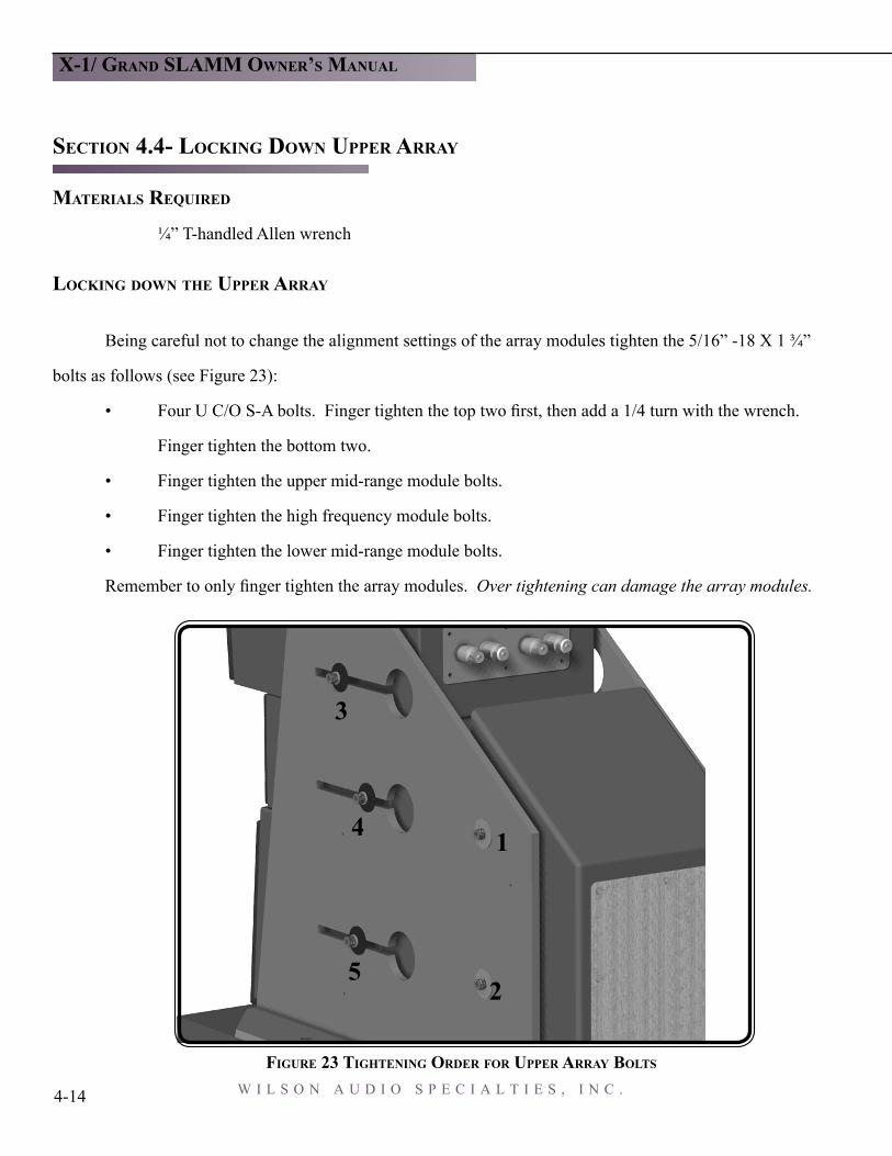
Being careful not to change the alignment settings of the array modules tighten the 5/16” -18 X 1 ¾”
bolts as follows (see Figure 23):
• Four U C/O S-A bolts. Finger tighten the top two first, then add a 1/4 turn with the wrench.
Finger tighten the bottom two.
• Finger tighten the upper mid-range module bolts.
• Finger tighten the high frequency module bolts.
• Finger tighten the lower mid-range module bolts.
Remember to only finger tighten the array modules. Over tightening can damage the array modules.
FIGURE 23 TIGHTENING ORDER FOR UPPER ARRAY BOLTS
5
4
3
2
1

W I L S O N A U D I O S P E C I A L T I E S , I N C . 4-15
X-1/ GRAND SLAMM OWNER’S MANUAL S E C T I O N 4 . 5 S P I K E I N S T A L L A T I O N
SECTION 4.5- SPIKE INSTALLATION
Note: This is a 2 person job. Do not attempt this with a single person. The X-1/Grand SLAMMs weigh over 650-lbs. and may seriously injure someone if tipped over.
MATERIALS REQUIRED
• 3/32 T-handled Allen wrench
• 8 sets of spikes
• 2, 6 foot set-up poles
• ¾” open ended wrenchINSTALLATION PROCEDURE
• Using the supplied 3/32 T-
handled allen wrench, Re-
move the hole covers located
on the base by remov ing the 4-40 screws (see Figure 24).
• Insert the two metal poles through the holes as shown in Figure 25.
• Have one
person slowly push down
on the 2 poles. This will
tip the Grand SLAMMs to
the proper angle for caster
removal and spike insertion.
While one person holds the
poles down have the other
person stand on those poles.
BASE HOLE
FIGURE 24 BASE HOLE COVERS
SET-UP POLESSTEP HERE
FLOOR
HOLD WITH HANDS
FIGURE 25 TILTING FOR SPIKE INSTALLATION

W I L S O N A U D I O S P E C I A L T I E S , I N C . 4-16
X-1/ GRAND SLAMM OWNER’S MANUAL
REMOVE CASTOR
CASTOR HOLE
SPIKE HOLE
INSTALL SPIKE
FIGURE 26 INSTALLING SPIKES
FIGURE 27 X-1 TILTED WITH SPIKE INSTALLED
• Use the open-ended
wrench to loosen the casters and
insert the finished spike assembly.
Screw in the spike assembly. Hand
tighten only! Note: Be very care-
ful NOT TO CROSS THREAD the
spikes. The base of the X-1/Grand
SLAMMs are made of “X” mate-
rial and are prone to cross threading.
Note: The spike will go into a differ-
ent hole than the caster. (see Figure
26)
Perform this operation on the
2 casters that are lifted by the poles.
With one person holding the
Grand SLAMMs, have the per-
son standing on the poles grasp
them in their hands. This person
will now lower the X-1/ Grand
SLAMM onto the spikes.
Note: The X-1 G

W I L S O N A U D I O S P E C I A L T I E S , I N C . 4-17
X-1/ GRAND SLAMM OWNER’S MANUAL S E C T I O N 4 . 5 S P I K E I N S T A L L A T I O N
Repeat the previous process of the caster removal/spike insertion on the opposite side of the enclo-
sure. Then continue the process on the other channel (see Figure 28).
FIGURE 28 INSTALLING SPIKES ON SECOND SIDE
REMOVE CASTERS

W I L S O N A U D I O S P E C I A L T I E S , I N C . 4-18
LEVELING THE X-1/GRAND SLAMMS
• Place a level on the left to right oriented axis. If it is level, move on to the next section.
• If the bubble is leaning toward the center of the room, you will have to bring one of the
outside spikes down toward the floor. If the bubble is leaning toward the outside of the
room, you will have to bring one of the inside spikes down toward the floor.
Note: To find out which spike to lower grasp the Grand SLAMM channel and rock it back and forth.
• Place a level on the front to back oriented axis. If it is level then your X-1 Grand SLAMMs
are level. If the bubble is leaning toward the front of the room you will have to bring one of
the front spikes down toward the floor. If the bubble is leaning toward the back of the room
(behind the loudspeakers) you will have to bring one of the front spikes down toward the
floor.
• Your X-1/Grand SLAMMs should now be level
X-1/ GRAND SLAMM OWNER’S MANUAL

W I L S O N A U D I O S P E C I A L T I E S , I N C . 4-19
X-1/ GRAND SLAMM OWNER’S MANUAL S E C T I O N 4 . 6 C H E C K I N G F O R P R O P E R I M A G E Height
SECTION 4.6-CHECKING FOR THE IMAGE HEIGHT
Once the X-1/Grand SLAMMs are properly spiked, check for the proper image height. Small differ-
ences in measurement of the listening distance can cause the image height to be too high. Check X-1 Grand
SLAMMs for the correct height as follows:
1 Sit in your listening position and listen to a piece of vocal performance that you know well.
Is the image height too high? If it is not too high, then proceed to installing the fascia on
your X-1/Grand SLAMMs. If it is too high follow the next few steps.
Note: Perform the following steps on both channels of your system.
2 Loosen the bolts that are holding your modules in place. You should also loosen the bolts
holding the crossovers in place.
3 Write down the number of increments that each module is set at (i.e. lower frequency module
is at 6 and 2 1/2 tics).
4 Starting from the lower frequency modules on each channel, move the arrays 1 1/2 incre-
ments to the front of the X-1/Grand SLAMMs. So in the case that I have stated, it would be
6 and 4 tics. Note: If you are careful, the entire array (all 3 modules) will move 1½.
5 Check to see that all 3 modules are correctly placed and then tighten them down on each
channel.
Note: Remember to tighten all of the crossover bolts, then check the modules for tightness.

W I L S O N A U D I O S P E C I A L T I E S , I N C . 4-20
X-1/ GRAND SLAMM OWNER’S MANUAL
SECTION 4.7-ATTACHING THE FASCIA’S
REQUIRED MATERIALS:
• 2, 10-32x1” screws
• 8, 10-32x1¾” screws
• 10, Fascia Hole Covers
• 1, 5/32 T-handled Allen wrench
ATTACHMENT PROCEDURE:
• Insert the 10-32x1¾” screws
into the 4 lower holes on each
fascia.
• Insert the 10-32x1” screws into the upper hole on each fascia.
• Tighten each screw firmly but do not over tighten them.
• Place the fascia hole covers over the screw
heads.
Lastly, reinstall the base hole covers using the 4-40x ¼”
screws and 3/32 T-handled wrench. Again, make sure to not over
tighten the screws. Store the crates for future use, sending speak-
ers back to the factory for upgrades, moving, etc.
10-32X1 3/4” SOCKET HEADED CAPSCREW
FIGURE 29 SCREW LOCATIONS ON THE
FASCIA HOLE
FIGURE 30 FINISHED UPPER ARRAY

W I L S O N A U D I O S P E C I A L T I E S , I N C . 4-21
X-1/ GRAND SLAMM OWNER’S MANUAL


5W A R R A N T Y I N F O R M A T I O N

W I L S O N A U D I O S P E C I A L T I E S , I N C .
X-1/ GRAND SLAMM OWNER’S MANUAL

W I L S O N A U D I O S P E C I A L T I E S , I N C .
WILSON AUDIO LOUDSPEAKER
L I M I T E D W A R R A N T Y TERMS AND CONDITIONS
LIMITED WARRANTY
Wilson Audio warrants its loudspeakers to be free of manufacturing defects in material and workman-ship, subject to the conditions hereinafter set forth for a period of 90 days from the date of purchase by the original purchaser, of five (5) years, if a Warranty Registration Form has been correctly filed at Wilson Audio, no later than 30 days after product delivery to the customer.
CONDITIONS
This warranty is subject to the following conditions and limitations. The Warranty is void and inap-plicable if the product has been used or handled other than in accordance with the instructions in the owner’s manual, abused or misused, damaged by accident or neglect or in being transported or the defect is due to the product being repaired or tampered with by anyone other than Wilson Audio, or an authorized repair center. Most repairs can be made in the field by an authorized Wilson Audio agent. In instances when return to Wilson Audio’s factory is required, a return authorization must first be obtained by the dealer or customer. Wilson Audio will pay return freight of its choice. A RETURNED PRODUCT MUST BE ACCOMPANIED BY A WRITTEN DESCRIPTION OF THE DEFECT. Wilson Audio reserves the right to modify the design of any product without obligation to purchasers of previously manufactured prod-ucts and to change the prices or specifications of any product without notice or obligation to any per-son.
REMEDY
In the event that the above product fails to meet the above Warranty and the above conditions have been met, the purchaser’s sole remedy under this Limited Warranty shall be to return the product to Wilson Audio or to an authorized Wilson Audio repair center where the defect will be rectified without charge for parts or labor.
S E C T I O N 5 . 0 W A R R A N T Y I N F O R M A T I O N
5-1
X-1/ GRAND SLAMM OWNER’S MANUAL

W I L S O N A U D I O S P E C I A L T I E S , I N C .
LIMITED TO ORIGINAL PURCHASER
This Warranty is for the sole benefit of the original purchaser of the covered product and shall not be transferred to a subsequent purchaser of the product. Any subsequent purchaser should contact a Wil-son Audio dealer to request a new warranty.
DEMONSTRATION EQUIPMENT
Equipment used by an authorized dealer for demonstration purposes is warranted to be free of manu-facturing defects in materials and workmanship for a period of five (5) years from the date of shipment to the dealer. Demo equipment needing warranty service may be repaired on-site or, if necessary, cor-rectly packed and returned to Wilson Audio by the dealer at his sole expense. Wilson Audio will pay return freight of its choice. A returned product must be accompanied by a written description of the defect. Dealer owned demonstration equipment sold at retail within two (2) years of date of shipment to the dealer is warranted to the first retain customer to be free of manufacturing defects in materials and workmanship for the same time periods as if the product had originally been bought for immedi-ate resale to the retail customer. In other words, 90 Day basic warranty, unless extended to 5 years by return of completed Warranty Registration.
MISCELLANEOUS
ANY IMPLIED WARRANTIES RELATING TO THE ABOVE PRODUCT SHALL BE LIMITED TO THE DURATION OF THIS WARRANTY. THE WARRANTY DOES NOT EXTEND TO ANY INCIDENTAL OR CONSEQUENTIAL COSTS OR DAMAGES TO THE PURCHASER. Some states do not allow limitations on how long an implied war-ranty lasts or an exclusion or limitation of incidental or consequential damages, so the above limitations or exclusions may not apply to you. This Warranty gives you specific legal rights, and you may also have other rights which vary from state to state
5-2
X-1/ GRAND SLAMM OWNER’S MANUAL

W I L S O N A U D I O S P E C I A L T I E S , I N C .
S E C T I O N 5 . 0 W A R R A N T Y I N F O R M A T I O N
5-3
X-1/ GRAND SLAMM OWNER’S MANUAL


6T R O U B L E S H O O T I N G

W I L S O N A U D I O S P E C I A L T I E S , I N C .
FBar

W I L S O N A U D I O S P E C I A L T I E S , I N C .
SECTION 6.0 TROUBLESHOOTING SETUP DIFFICULTIES
Problem ReasonOne channel is not operating... Check inter-connects from source.
Check the connections on the speaker cables. Both at am-
plifier and speaker ends. Watch especially for connector touch-ing each other.
Check the Upper Range Signal Cable, you may have forgotten to connect them, or they may have shorted or come loose dur-ing setup (see Figure 19, page 4-7).
Imaging is off center... Check your connections. One of the connections to the mod-ules may have slipped off. When a tweeter or mid-range driver is not working, or is out of phase, the imaging will be off. Dou-ble check your connections for red-to-red and black-to-black.
Play music at a low level, and listen to each driver in each channel. You may have a driver that is not operating correctly. If you find a driver that is silent please go to the “Driver Out section” of this troubleshooting guide.
A chronic lack of bass energy... Check the input cable connections on your woofer en-closure. If one channel is out of phase (connections reversed), bass will be cancelled.
Driver out not playing after Note: Turn off your amplifier, and unplug it from the wall.connections have beenverified.
If you have found a driver that would not play, move to the rear of this particular loudspeaker.
Using the appropriate Allen key, Open the small aluminum door on the back of the upper crossover. You will find some resistor connec tions, which are labeled “Low-er Midrange”, “Ultra High Frequency”, and “Upper Mid-range”.
S E C T I O N 6 . 0 T R O U B L E S H O O T I N G
6-1
FBar

W I L S O N A U D I O S P E C I A L T I E S , I N C .
Replace the resistor with the supplied matching resistor. Tight-en the new resistor in the old ones place.
Note: An improper resistor value will deteriorate your speaker perfor mance
Plug your amplifier into the wall and turn it on.
Listen to the channel at a low level. The driver should now be operat ing correctly.
Amplifier shuts off as soon as it is turned on: Check to see if your speaker cables are properly secured. Look for frayed ends, loose connections, a conductor contact-ing the amplifier chassis.
Turn the amplifier off and disconnect it from the AC wall outlet. Dis connect the preamplifier leads to the amplifier. Now turn back on the amplifier.
If the problem is solved: There is something wrong with your pream plifier or interconnect. Call your dealer.
If the problem persists: Leave the pre-amp leads disconnect-ed and continue on to the next step.
Turn the amplifier off and disconnect it from the AC wall outlet. Dis connect the speaker leads at the main input to the speaker . Now turn the amplifier on.
6-2
X-1/ GRAND SLAMM OWNER’S MANUAL

W I L S O N A U D I O S P E C I A L T I E S , I N C .
If the problem is solved: Call your Wilson Audio dealer. There may be a problem with the crossover or the speakerʼs internal wiring.
If the problem persists continue on to the next step.
Turn the amplifier off and disconnect it from the AC wall outlet. Disconnect the speaker cable leads to the amplifier and turn the amplifier on again.
If the problem is solved: You have a short in your speaker cables. Check for frayed ends, holes (from spike feet), or make sure that your spade lug is not touching the chassis while it is connected to the binding post.
If the problem persists: Call the dealer where you bought your
S E C T I O N 6 . 0 T R O U B L E S H O O T I N G
6-3
X-1/ GRAND SLAMM OWNER’S MANUAL


7S P E C I F I C A T I O N S

W I L S O N A U D I O S P E C I A L T I E S , I N C .

W I L S O N A U D I O S P E C I A L T I E S , I N C .
S E C T I O N 7 . 0 S P E C I F I C A T I O N S
7-1
SECTION 7.0- SPECIFICATIONS
Enclosure Type: Ported - Woofer
Closed - Mid Frequency
Closed - High Frequency
Woofer Diameter: 1 - 12 Inch, 30.5 cm
1 - 15 Inch, 38 cm
Mid Frequency Diameter: 2 - 7 Inch, 18 cm
Tweeter Diameter: 1 - 1 Inch Forward Firing
2 - 1 Inch Rearward Firing
Sensitivity: 95 dB (2.83 Volts at 1 meter)
Frequency Response: 19.5 Hz to 22.5 kHz (-3dB SPL)
Minimum Amp Power: 20 Watts/per channel
Standard Finishes: Wilson Gloss
Overall Dimensions: Height - 72 Inches, 183 cm
Width - 16 1/2 Inches, 42 cm
Depth - 25 1/4 Inches, 64 cm
Approximate shipping weight complete system: 1808 lbs., 824 kilograms
Approximate channel weight: 600 lbs., 272 kilograms
Warranty: 5 year transferable


AA P P E N D I X

W I L S O N A U D I O S P E C I A L T I E S , I N C .

W I L S O N A U D I O S P E C I A L T I E S , I N C .
A P P E N D I X A T I M I N G T A B L E S
A-1