Wild Thumper Robot Kit (#28192) - Parallax, Inc. · Title: Wild Thumper Robot Kit (#28192) Author:...
12
Web Site: www.parallax.com Forums: forums.parallax.com Sales: [email protected] Technical: [email protected] Office: (916) 624-8333 Fax: (916) 624-8003 Sales: (888) 512-1024 Tech Support: (888) 997-8267 Copyright © Parallax Inc. Wild Thumper Robot Kit (#28192) Page 1 of 12 Wild Thumper Robot Kit (#28192) Information and Assembly Guide The Wild Thumper Robot Kit pairs the Dagu Thumper Robot chassis and motor system with Parallax’s Propeller Project Board USB and HB-25 Motor Controllers. Whether you are designing for remote control or autonomous navigation, the multicore Propeller P8X32A makes it simple to integrate the custom features you choose for your Thumper robot’s drive system. Features Six brass-brushed DC motors with 34:1 gearboxes for maximum torque and speed Adjustable suspension accommodates different load sizes 2 mm thick corrosion-resistant anodized aluminum chassis plates for enhanced durability and longevity Two underbody compartments enabling protection of your power supply and motor controllers 4 mm holes spaced every 10 mm provide many mounting options for additional sensors, electronics and hardware Specifications Control board voltage: 5.5 to 16 VDC Motor voltage: 2.0 to 7.5 VDC Motor Current: 6.6 A stall, 420 mA no-load Top speed: 4.5 mph (7.2 km/h) @ 7.4 VDC Weight: 7 lbs (3.17 kg) Payload capacity: 11 lbs (5 kg) Average assembly time: 2 hours Dimensions (assembled): 16 x 12 x 7 in (41 x 30.5 x 18 cm) Additional Items Required Power supply or battery pack and charger Tools for assembly (see the next page) Application Ideas Hobby RC vehicle racing over extreme terrain Autonomous vehicle navigation contests Rolling tele-presence platform for fun or research
Transcript of Wild Thumper Robot Kit (#28192) - Parallax, Inc. · Title: Wild Thumper Robot Kit (#28192) Author:...
Web Site: www.parallax.com Forums: forums.parallax.com Sales: [email protected] Technical: [email protected]
Office: (916) 624-8333 Fax: (916) 624-8003 Sales: (888) 512-1024 Tech Support: (888) 997-8267
Copyright © Parallax Inc. Wild Thumper Robot Kit (#28192) Page 1 of 12
Wild Thumper Robot Kit (#28192) Information and Assembly Guide The Wild Thumper Robot Kit pairs the Dagu Thumper Robot chassis and motor system with Parallax’s Propeller Project Board USB and HB-25 Motor Controllers. Whether you are designing for remote control or autonomous navigation, the multicore Propeller P8X32A makes it simple to integrate the custom features you choose for your Thumper robot’s drive system.
Features Six brass-brushed DC motors with 34:1 gearboxes for maximum
torque and speed
Adjustable suspension accommodates different load sizes
2 mm thick corrosion-resistant anodized aluminum chassis plates for enhanced durability and longevity
Two underbody compartments enabling protection of your power supply and motor controllers
4 mm holes spaced every 10 mm provide many mounting options for additional sensors, electronics and hardware
Specifications Control board voltage: 5.5 to 16 VDC
Motor voltage: 2.0 to 7.5 VDC
Motor Current: 6.6 A stall, 420 mA no-load
Top speed: 4.5 mph (7.2 km/h) @ 7.4 VDC
Weight: 7 lbs (3.17 kg)
Payload capacity: 11 lbs (5 kg)
Average assembly time: 2 hours
Dimensions (assembled): 16 x 12 x 7 in (41 x 30.5 x 18 cm)
Additional Items Required Power supply or battery pack and charger
Tools for assembly (see the next page)
Application Ideas Hobby RC vehicle racing over extreme terrain
Autonomous vehicle navigation contests
Rolling tele-presence platform for fun or research
Copyright © Parallax Inc. Wild Thumper Robot Kit (#28192) Page 2 of 12
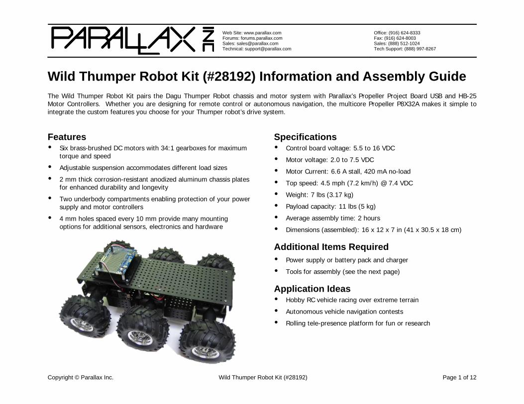
Bill of Materials This bill of materials is provided so you may inventory your kit before beginning construction. Note that some items are small sub-kits that include additional components not listed separately. Parts and quantities subject to change without notice. Some items are available online from www.parallax.com.
Part # Quantity Description
28191 1 Dagu Thumper Robot Kit
29144 2 HB-25 Motor Controller
32810 1 Propeller Project Board USB
451-04001 1 20-pin Single Row Header
452-00090 8 14-16 AWG #8 Ring Terminal
700-00002 4 Screw, #4-40, 3/8", Panhead
700-00024 4 Locknut, #4-40, 1/4"
700-00086 4 Screw, #6-32, 1/4", Cap
710-00007 4 Screw, #4-40, 7/8" Panhead
710-00100 4 Screw, #4-40, 1/4", Panhead, black
713-00005 4 Spacer, #4, 1/4", Nylon
713-00043 4 Standoff, #4-40, 5/8", Nylon
721-00040 1 Wild Thumper Control Board Mount Plate
750-00050 2.5’ Wire, 14 AWG, Black
750-00051 2.5’ Wire, 14 AWG, Red
800-00023 12” Heat-shrink Tubing, 3/16"
800-00060 2 3-wire extension cable, 22AWG, F/F, 6"
Assembly Instructions These instructions are for assembling the Wild Thumper Robot Kit in its most standard configuration. This robotic platform is designed for creative experimentation and adaptation; however, we recommend that you try the standard configuration first, then experiment at your own educated risk.
Preparation Read the entire assembly instructions before beginning. Assembly and testing takes about 2 hours on average.
1. If you are missing any components, email [email protected] or call 888-512-1024 (inside continental US) or 916-624-8333.
2. Gather all of the additional items and tools required
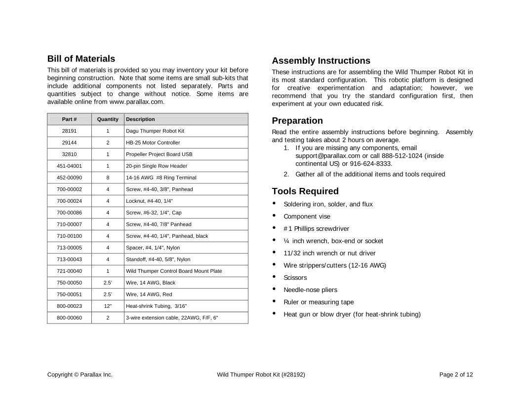
Tools Required Soldering iron, solder, and flux
Component vise
#1 Phillips screwdriver
¼ inch wrench, box-end or socket
11/32 inch wrench or nut driver
Wire strippers/cutters (12-16 AWG)
Scissors
Needle-nose pliers
Ruler or measuring tape
Heat gun or blow dryer (for heat-shrink tubing)
Copyright © Parallax Inc. Wild Thumper Robot Kit (#28192) Page 3 of 12
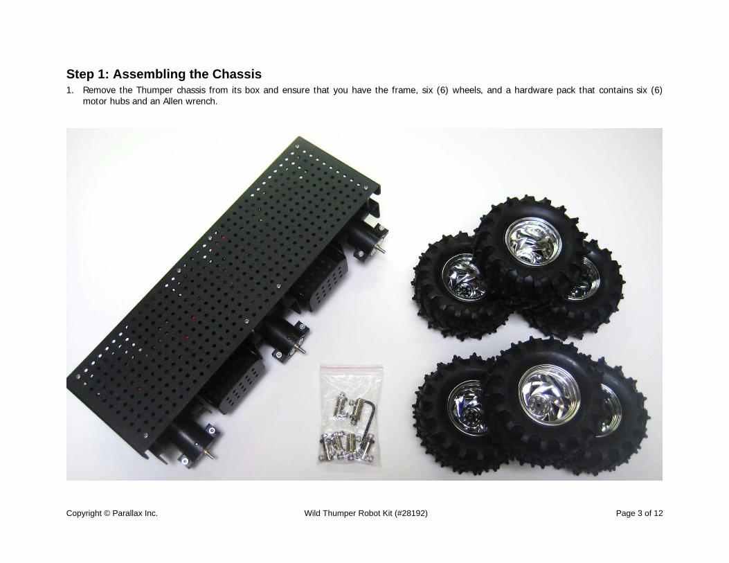
Step 1: Assembling the Chassis 1. Remove the Thumper chassis from its box and ensure that you have the frame, six (6) wheels, and a hardware pack that contains six (6)
motor hubs and an Allen wrench.
Copyright © Parallax Inc. Wild Thumper Robot Kit (#28192) Page 4 of 12
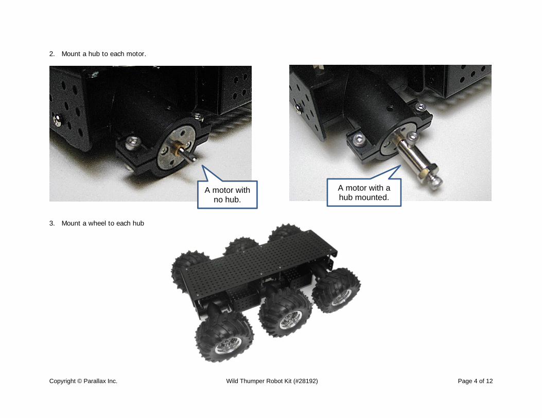
2. Mount a hub to each motor.
3. Mount a wheel to each hub
A motor with no hub.
A motor with a hub mounted.
Copyright © Parallax Inc. Wild Thumper Robot Kit (#28192) Page 5 of 12
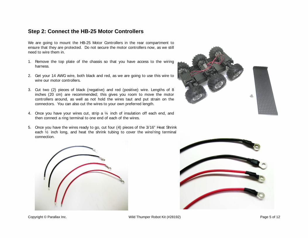
Step 2: Connect the HB-25 Motor Controllers We are going to mount the HB-25 Motor Controllers in the rear compartment to ensure that they are protected. Do not secure the motor controllers now, as we still need to wire them in. 1. Remove the top plate of the chassis so that you have access to the wiring
harness. 2. Get your 14 AWG wire, both black and red, as we are going to use this wire to
wire our motor controllers. 3. Cut two (2) pieces of black (negative) and red (positive) wire. Lengths of 8
inches (20 cm) are recommended; this gives you room to move the motor controllers around, as well as not hold the wires taut and put strain on the connectors. You can also cut the wires to your own preferred length.
4. Once you have your wires cut, strip a ¼ inch of insulation off each end, and then connect a ring terminal to one end of each of the wires.
5. Once you have the wires ready to go, cut four (4) pieces of the 3/16” Heat Shrink
each ½ inch long, and heat the shrink tubing to cover the wire/ring terminal connection.
Copyright © Parallax Inc. Wild Thumper Robot Kit (#28192) Page 6 of 12
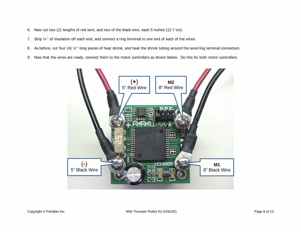
6. Now cut two (2) lengths of red wire, and two of the black wire, each 5 inches (12.7 cm).
7. Strip ¼” of insulation off each end, and connect a ring terminal to one end of each of the wires.
8. As before, cut four (4) ½” long pieces of heat shrink, and heat the shrink tubing around the wire/ring terminal connection. 9. Now that the wires are ready, connect them to the motor controllers as shown below. Do this for both motor controllers.
(+) 5” Red Wire
M2 8” Red Wire
(-) 5” Black Wire
M1 8” Black Wire
Copyright © Parallax Inc. Wild Thumper Robot Kit (#28192) Page 7 of 12
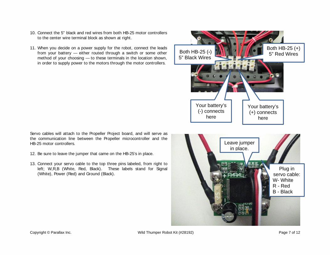
10. Connect the 5” black and red wires from both HB-25 motor controllers to the center wire terminal block as shown at right.
11. When you decide on a power supply for the robot, connect the leads
from your battery — either routed through a switch or some other method of your choosing — to these terminals in the location shown, in order to supply power to the motors through the motor controllers.
Servo cables will attach to the Propeller Project board, and will serve as the communication line between the Propeller microcontroller and the HB-25 motor controllers. 12. Be sure to leave the jumper that came on the HB-25’s in place. 13. Connect your servo cable to the top three pins labeled, from right to
left; W,R,B (White, Red, Black). These labels stand for Signal (White), Power (Red) and Ground (Black).
Leave jumper in place.
Both HB-25 (-) 5” Black Wires
Both HB-25 (+) 5” Red Wires
Plug in servo cable: W- White R - Red B - Black
Your battery’s (-) connects
here
Your battery’s (+) connects
here
Copyright © Parallax Inc. Wild Thumper Robot Kit (#28192) Page 8 of 12
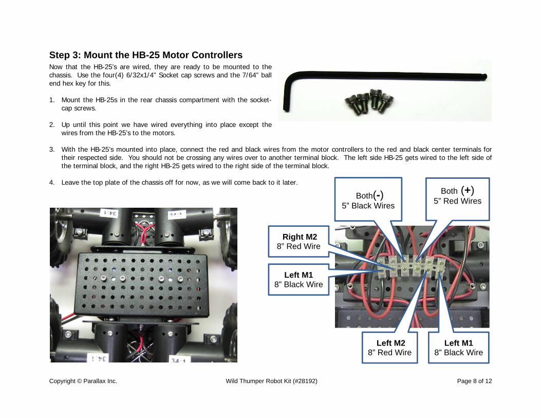
Step 3: Mount the HB-25 Motor Controllers Now that the HB-25’s are wired, they are ready to be mounted to the chassis. Use the four(4) 6/32x1/4” Socket cap screws and the 7/64” ball end hex key for this. 1. Mount the HB-25s in the rear chassis compartment with the socket-
cap screws. 2. Up until this point we have wired everything into place except the
wires from the HB-25’s to the motors. 3. With the HB-25’s mounted into place, connect the red and black wires from the motor controllers to the red and black center terminals for
their respected side. You should not be crossing any wires over to another terminal block. The left side HB-25 gets wired to the left side of the terminal block, and the right HB-25 gets wired to the right side of the terminal block.
4. Leave the top plate of the chassis off for now, as we will come back to it later.
Both(-)
5” Black Wires
Both (+) 5” Red Wires
Left M2 8” Red Wire
Left M1 8” Black Wire
Right M2 8” Red Wire
Left M1 8” Black Wire
Copyright © Parallax Inc. Wild Thumper Robot Kit (#28192) Page 9 of 12
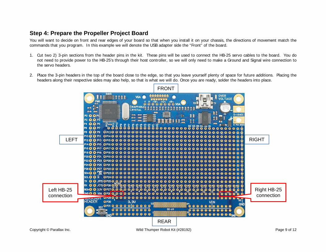
Step 4: Prepare the Propeller Project Board You will want to decide on front and rear edges of your board so that when you install it on your chassis, the directions of movement match the commands that you program. In this example we will denote the USB adapter side the “Front” of the board. 1. Cut two 2) 3-pin sections from the header pins in the kit. These pins will be used to connect the HB-25 servo cables to the board. You do
not need to provide power to the HB-25’s through their host controller, so we will only need to make a Ground and Signal wire connection to the servo headers.
2. Place the 3-pin headers in the top of the board close to the edge, so that you leave yourself plenty of space for future additions. Placing the
headers along their respective sides may also help, so that is what we will do. Once you are ready, solder the headers into place.
FRONT
REAR
RIGHT LEFT
Left HB-25 connection
Right HB-25 connection
Copyright © Parallax Inc. Wild Thumper Robot Kit (#28192) Page 10 of 12
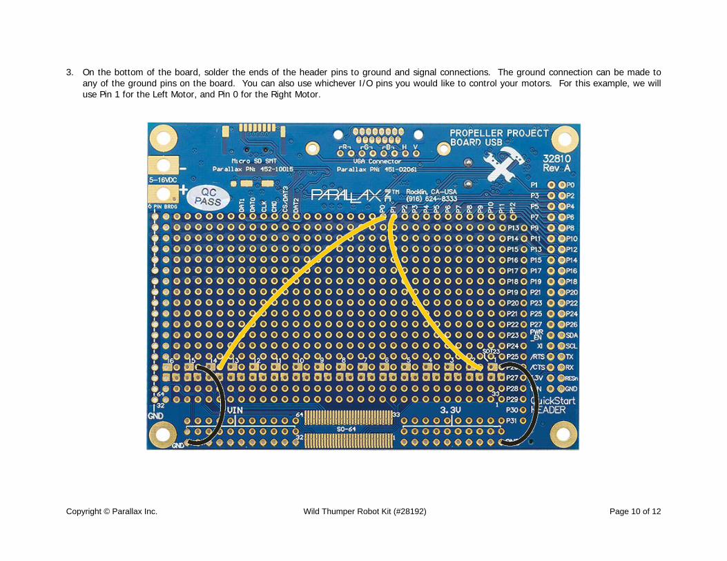
3. On the bottom of the board, solder the ends of the header pins to ground and signal connections. The ground connection can be made to any of the ground pins on the board. You can also use whichever I/O pins you would like to control your motors. For this example, we will use Pin 1 for the Left Motor, and Pin 0 for the Right Motor.
Copyright © Parallax Inc. Wild Thumper Robot Kit (#28192) Page 11 of 12
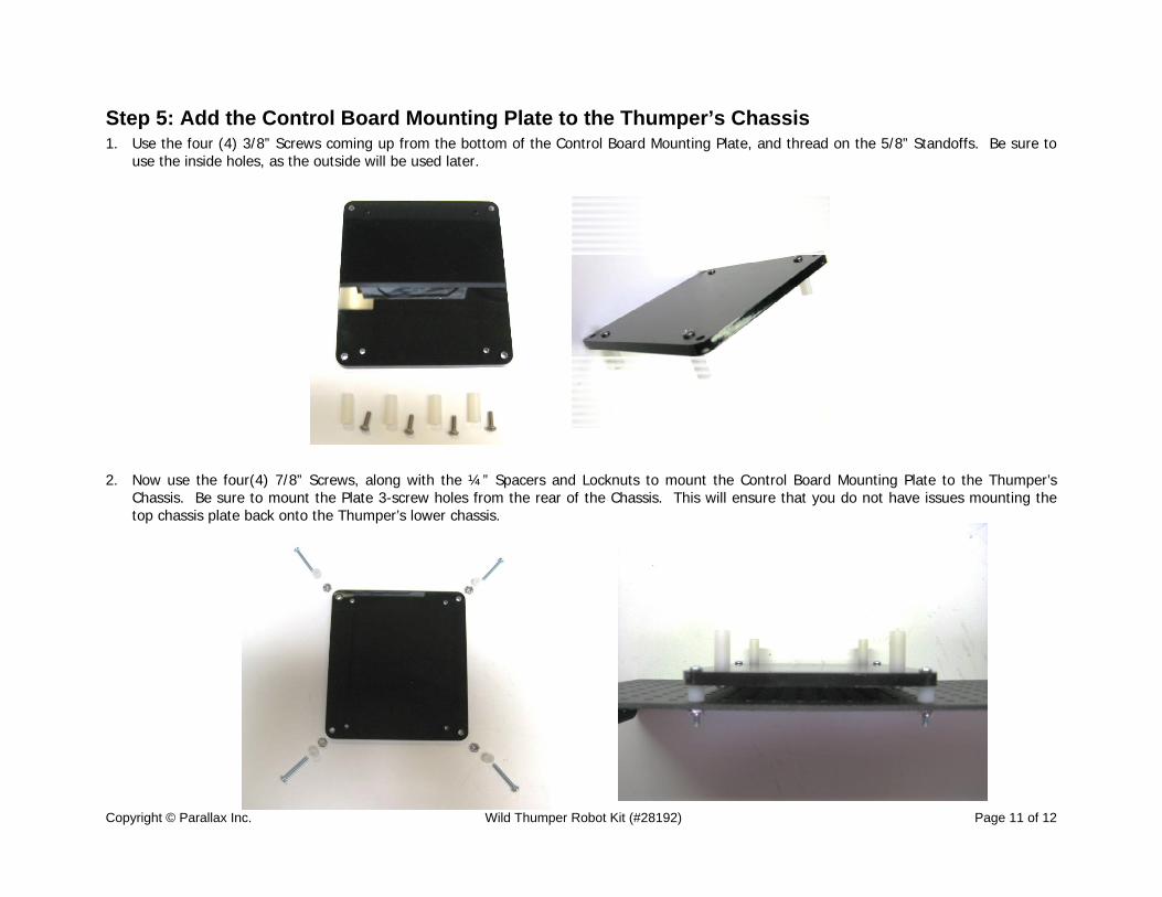
Step 5: Add the Control Board Mounting Plate to the Thumper’s Chassis 1. Use the four (4) 3/8” Screws coming up from the bottom of the Control Board Mounting Plate, and thread on the 5/8” Standoffs. Be sure to
use the inside holes, as the outside will be used later. 2. Now use the four(4) 7/8” Screws, along with the ¼” Spacers and Locknuts to mount the Control Board Mounting Plate to the Thumper’s
Chassis. Be sure to mount the Plate 3-screw holes from the rear of the Chassis. This will ensure that you do not have issues mounting the top chassis plate back onto the Thumper’s lower chassis.
Copyright © Parallax Inc. Wild Thumper Robot Kit (#28192) Page 12 of 12
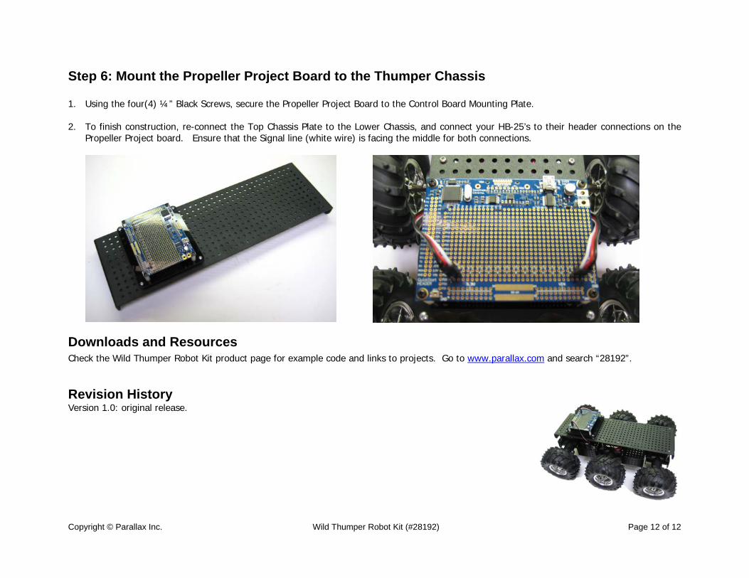
Step 6: Mount the Propeller Project Board to the Thumper Chassis 1. Using the four(4) ¼” Black Screws, secure the Propeller Project Board to the Control Board Mounting Plate. 2. To finish construction, re-connect the Top Chassis Plate to the Lower Chassis, and connect your HB-25’s to their header connections on the
Propeller Project board. Ensure that the Signal line (white wire) is facing the middle for both connections.
Downloads and Resources Check the Wild Thumper Robot Kit product page for example code and links to projects. Go to www.parallax.com and search “28192”. Revision History Version 1.0: original release.