Wideband Bandpass Filter With Reconfigurable Bandwidth-ZSN
3
28 IEEE MICROW AVE AND WIRELESS COMPONENTS LETTERS, VOL. 20, NO. 1, J ANUARY 2010 W ide ban d Ban dpa ss Filter W ith Reconfigurable Bandwidth Alexander Miller , Student Member , IEEE , and Jia-Sheng Hong , Senior Member , IEEE Abstract—this letter proposes a novel building block for devel- oping tunable wide band bandp ass filter s. The pro posed circui t block mai nly con sis ts of sho rt cir cui t cou ple d lin es and sho rt circuit stubs with pin diodes as tuning elements. This work aims to demonstrate reconfigurable bandwidth of this type of filter. Two filters are designed and fabricated; one can be switched between a fra cti ona l ban dwidt h (FBW) of 16.3% and 35% at a ce nte r frequency of 1.9 GHz, and the other can be switched from a FBW of 27.8% to 37.4% at a center frequency of 1.9 GHz. The insertion loss and return loss in the first filter range from 4.17 dB to 0.4 dB and 27.54 dB to 19.04 dB. The second filter exhibits an insertion loss ranging from 0.73 dB to 0.43 dB and a return loss range from 31.1 dB to 27.7 dB. The tested filters show good agreement with EM simulations. Index Terms—Bandpass filter, microstrip filter , tunable filter. I. INTRODUCTION A DV ANCES in many microwave systems and applications with multifunction capabilities means that there is an in- creasing demand to develop reconfigurable filters. Thus recon- figurable filters are essential for future wireless communica- tion systems across commercial, defense and civil sectors. In all these systems reconfigurable filter technologies hold the key to controlling the spectrum of RF signals, eliminating interference and preserving the dynamic range under any signal receiving condition. Reconfigurable filters can be realised in a variety of ways, but no matter what method of tuning is used they must conserve their transmission and reflection coefficient over the tuning range specified. They offer many advantages over tradi- tional filter banks, the main being size and flexibility. Many tunable filters have been investigated that control the center frequency [1]–[6]. The tunability of the center frequency is accomplished by varying the electrical lengths of filter res- onators; tunability is either continuous or in discrete steps with the use of varactors or pin diodes. Varactors were initially uti- lized and as the most popular choices being: Semiconducting [1], BST [2] and piezoelectric [3]. Conversely, in order to tune the center frequency in discrete steps pin diodes are employed [5]; however with the introduction of microelectromechanical systems switches, tuning the center frequency in discrete steps Manuscript received August 03, 2009; revised October 09, 2009. First pub- lished December 09, 2009; current version published January 08, 2010. This work was supported by in part by a UK EPSRC Industrial CASE Award. Alexander Miller and Jia-Sheng Hong are with Department of Electrical, Electronic and Computer Engineer ing, School of Engineering and Phys - ical Sciences, Heriot-Watt Uni versity, Edin bur gh, EH14 4AS, U.K. Email: [email protected] , [email protected]. Color versions of one or more of the figures in this paper are available online at http://ieeexp lore.ieee.org. Digital Object Identifier 10.1109/LMWC.2009.20 35958 has been gaining more popularity due to their low RF losses and dc consumption [6]. In comparison to tunability of center frequency, there has bee n ve ry lit tle effor t mad e in tunabilit y of ban dwi dth . A reason for this is the lack of methods to vary the inter-resonator coupling electronically that is essential for bandwidth control. There have been some papers that tackle this subject in a variety of ways , some concentratin g on the tunab ility of bandwidth at a fixed center frequency [7], [8] and others dealing with simul- taneous control of both bandwidth and center frequency [9], [10]. On inspection of the literature it is clear that most reported filter topologies and methods used only apply to narrowband applications. However, there is increasing demand for tunable wideband filters. Typical applications would be receiver mod- ules and RF converters where filter banks can be replaced by such a filter in order to save board space. This letter investigates a new topology to realise such a filter with a reconfigurable bandwidth. The tuning elements used are pin diodes, as they are much less lossy than the varactor diodes, thus limiting the degradation in passband width and filter operation. II. FILTER BUILDING BLOCK Shown in Fig. 1 is the proposed filter building block, which mainly consist s of short -circu ited coupled lines and stubs that have an electri cal lengt h of 90 at the cente r frequenc y of the passband. The tunability of the proposed filter is based on the conce pt that, for a giv en pair of coupled lines with fixed eve n- and odd-mode impedance, altering the impedance of the stubs alters the coupling and in turn alters the bandwidth, hence, by switching the stubs in and out of the circuit alters the passband width. It can be shown that the return loss in the passband only depends on the pair of even- and odd- mode impedances and is independent of the characteristic impedance of the other stubs (see Fig. 2). This makes bandwidth tuning easy. In addition to this advantage, by simply cascading several same filter blocks of this type, a higher order filter that increases the selectivity while theoretically maintaining the same return loss over the same bandwidth can be built. This trait is very desirable whilst des ign ing wid eband filters wit h a reconfigur able ban dwidth(see Fig. 3). II I. EXPERIMENTAL DEMONSTRATION To validate the circuit concept described in the above section, two reconfigurable filter building blocks were designed, simu- lated and tested. A. EM Simulation Fig. 4 shows an implemented reconfigurable microstrip filter on a substrate with and mm. The pin diodes were modeled by using a capacitor of value 0.025 pF for isol at ion and a resi stor of va lue of 4 for connec ti on (bot h these 1531-1309/$26.00 © 2009 IEEE AlultIXDoM1a1UfIX Ra
-
Upload
denis-medina-adame -
Category
Documents
-
view
230 -
download
0
Transcript of Wideband Bandpass Filter With Reconfigurable Bandwidth-ZSN

7/26/2019 Wideband Bandpass Filter With Reconfigurable Bandwidth-ZSN
http://slidepdf.com/reader/full/wideband-bandpass-filter-with-reconfigurable-bandwidth-zsn 1/3
28 IEEE MICROWAVE AND WIRELESS COMPONENTS LETTERS, VOL. 20, NO. 1, JANUARY 2010
Wideband Bandpass Filter WithReconfigurable Bandwidth
Alexander Miller , Student Member, IEEE , and Jia-Sheng Hong , Senior Member, IEEE
Abstract—this letter proposes a novel building block for devel-oping tunable wideband bandpass filters. The proposed circuitblock mainly consists of short circuit coupled lines and shortcircuit stubs with pin diodes as tuning elements. This work aims todemonstrate reconfigurable bandwidth of this type of filter. Twofilters are designed and fabricated; one can be switched betweena fractional bandwidth (FBW) of 16.3% and 35% at a centerfrequency of 1.9 GHz, and the other can be switched from a FBWof 27.8% to 37.4% at a center frequency of 1.9 GHz. The insertionloss and return loss in the first filter range from 4.17 dB to 0.4 dBand 27.54 dB to 19.04 dB. The second filter exhibits an insertionloss ranging from 0.73 dB to 0.43 dB and a return loss range from31.1 dB to 27.7 dB. The tested filters show good agreement with
EM simulations.
Index Terms—Bandpass filter, microstrip filter, tunable filter.
I. INTRODUCTION
ADVANCES in many microwave systems and applications
with multifunction capabilities means that there is an in-
creasing demand to develop reconfigurable filters. Thus recon-
figurable filters are essential for future wireless communica-
tion systems across commercial, defense and civil sectors. In all
these systems reconfigurable filter technologies hold the key to
controlling the spectrum of RF signals, eliminating interference
and preserving the dynamic range under any signal receiving
condition. Reconfigurable filters can be realised in a variety of
ways, but no matter what method of tuning is used they must
conserve their transmission and reflection coefficient over the
tuning range specified. They offer many advantages over tradi-
tional filter banks, the main being size and flexibility.
Many tunable filters have been investigated that control the
center frequency [1]–[6]. The tunability of the center frequency
is accomplished by varying the electrical lengths of filter res-
onators; tunability is either continuous or in discrete steps with
the use of varactors or pin diodes. Varactors were initially uti-
lized and as the most popular choices being: Semiconducting
[1], BST [2] and piezoelectric [3]. Conversely, in order to tunethe center frequency in discrete steps pin diodes are employed
[5]; however with the introduction of microelectromechanical
systems switches, tuning the center frequency in discrete steps
Manuscript received August 03, 2009; revised October 09, 2009. First pub-lished December 09, 2009; current version published January 08, 2010. Thiswork was supported by in part by a UK EPSRC Industrial CASE Award.
Alexander Miller and Jia-Sheng Hong are with Department of Electrical,Electronic and Computer Engineering, School of Engineering and Phys-ical Sciences, Heriot-Watt University, Edinburgh, EH14 4AS, U.K. Email:[email protected], [email protected].
Color versions of one or more of the figures in this paper are available onlineat http://ieeexplore.ieee.org.
Digital Object Identifier 10.1109/LMWC.2009.2035958
has been gaining more popularity due to their low RF losses and
dc consumption [6].
In comparison to tunability of center frequency, there has
been very little effort made in tunability of bandwidth. A
reason for this is the lack of methods to vary the inter-resonator
coupling electronically that is essential for bandwidth control.
There have been some papers that tackle this subject in a variety
of ways, some concentrating on the tunability of bandwidth at
a fixed center frequency [7], [8] and others dealing with simul-
taneous control of both bandwidth and center frequency [9],
[10]. On inspection of the literature it is clear that most reported
filter topologies and methods used only apply to narrowband
applications. However, there is increasing demand for tunable
wideband filters. Typical applications would be receiver mod-
ules and RF converters where filter banks can be replaced by
such a filter in order to save board space. This letter investigates
a new topology to realise such a filter with a reconfigurable
bandwidth. The tuning elements used are pin diodes, as they
are much less lossy than the varactor diodes, thus limiting the
degradation in passband width and filter operation.
II. FILTER BUILDING BLOCK
Shown in Fig. 1 is the proposed filter building block, which
mainly consists of short-circuited coupled lines and stubs thathave an electrical length of 90 at the center frequency of thepassband. The tunability of the proposed filter is based on theconcept that, for a given pair of coupled lines with fixed even-and odd-mode impedance, altering the impedance of the stubsalters the coupling and in turn alters the bandwidth, hence, byswitching the stubs in and out of the circuit alters the passbandwidth. It can be shown that the return loss in the passband onlydepends on the pair of even- and odd- mode impedances and isindependent of the characteristic impedance of the other stubs(see Fig. 2). This makes bandwidth tuning easy. In addition tothis advantage, by simply cascading several same filter blocksof this type, a higher order filter that increases the selectivitywhile theoretically maintaining the same return loss over the
same bandwidth can be built. This trait is very desirable whilstdesigning wideband filters with a reconfigurable bandwidth (seeFig. 3).
III. EXPERIMENTAL DEMONSTRATION
To validate the circuit concept described in the above section,two reconfigurable filter building blocks were designed, simu-lated and tested.
A. EM Simulation
Fig. 4 shows an implemented reconfigurable microstrip filteron a substrate with and mm. The pindiodes were modeled by using a capacitor of value 0.025 pF for
isolation and a resistor of value of 4 for connection (both these
1531-1309/$26.00 © 2009 IEEE
AlultIXDoM1a1UfIX Ra

7/26/2019 Wideband Bandpass Filter With Reconfigurable Bandwidth-ZSN
http://slidepdf.com/reader/full/wideband-bandpass-filter-with-reconfigurable-bandwidth-zsn 2/3
MILLER AND HONG: WIDEBAND BANDPASS FILTER WITHRECONFIGURABLE BANDWIDTH 29
Fig. 1. Proposed Filter Building Block for Reconfigurable Bandwidth.
Fig. 2. Theoretical response showing change of bandwidth with change of impedance of stub 0 , .
Fig. 3. Theoretical filter response with two blocks cascaded
0 0 .
values are extracted from the data sheet for the PIN diode used).For practical implementation, depending on a set of even- andodd- mode impedances implemented, impedance transformersmay or may not be needed at the terminals for a matching pur-
pose. The initial dimensions of the circuits were obtained usingMicrowave Office [11] and finalized using EM software, Sonnet[12]. The dimensions of the stubs are mmand mm (narrowband stubs) while the cou-pled lines have a gap mm, mm and
mm. In this case, the impedance transformerhas a width and length of 0.6 mm and 24.8 mm, respectively.
In Fig. 4, just replacing the narrowband stubs with two wide-band stubs mm and mm),we obtain the second reconfigurable filter block. The simulatedperformances of these two filters are summarized in Table I,with the simulated and measured performance being illustratedin Figs. 5 and 6.
There are some shifts in the center frequencies, which are ac-
counted for by unequal even and odd mode electrical lengths andsome effect from the bias circuit. Furthermore, these unequal
Fig. 4. Implemented filter with switchable stubs (narrowband stubs).
Fig. 5. Performance of Filter with Narrowband stubs.
Fig. 6. Performance of Filter with Wideband stubs.
even and odd mode phase velocities also cause the spurious re-
sponse at 4 GHz; the next spurious response should be at 6 GHz,i.e., 3 . Thisis due tothe fact that microstripare not pure TEMtransmission lines. There is also a very slight degradation in thebandwidth performance due to the bias lines being connectedin the middle of the coupled lines. The bias lines slightly de-crease the coupling and, hence, decrease the bandwidth of theresponse.
In the “on” state of the narrowband stub configuration thereis more losses associated with the response; this is due to theisolation scheme used in order to suppress any unwanted spikesin the passband due to fringing. By placing the diode half wayup the stub means there is a bigger current at this point, hence,more losses are involved. By simply using one diode for isola-tion a spike was seen near the passband which would be detri-
mental to filter operation. Many cases were tried the first beingthat a diode at the bottom of the stub and one at the top. This
AlultIXDoM1a1UfIX Ra
7/26/2019 Wideband Bandpass Filter With Reconfigurable Bandwidth-ZSN
http://slidepdf.com/reader/full/wideband-bandpass-filter-with-reconfigurable-bandwidth-zsn 3/3
30 IEEE MICROWAVE AND WIRELESS COMPONENTS LETTERS, VOL. 20, NO. 1, JANUARY 2010
TABLE IPERFORMANCE OF THE FILTERS
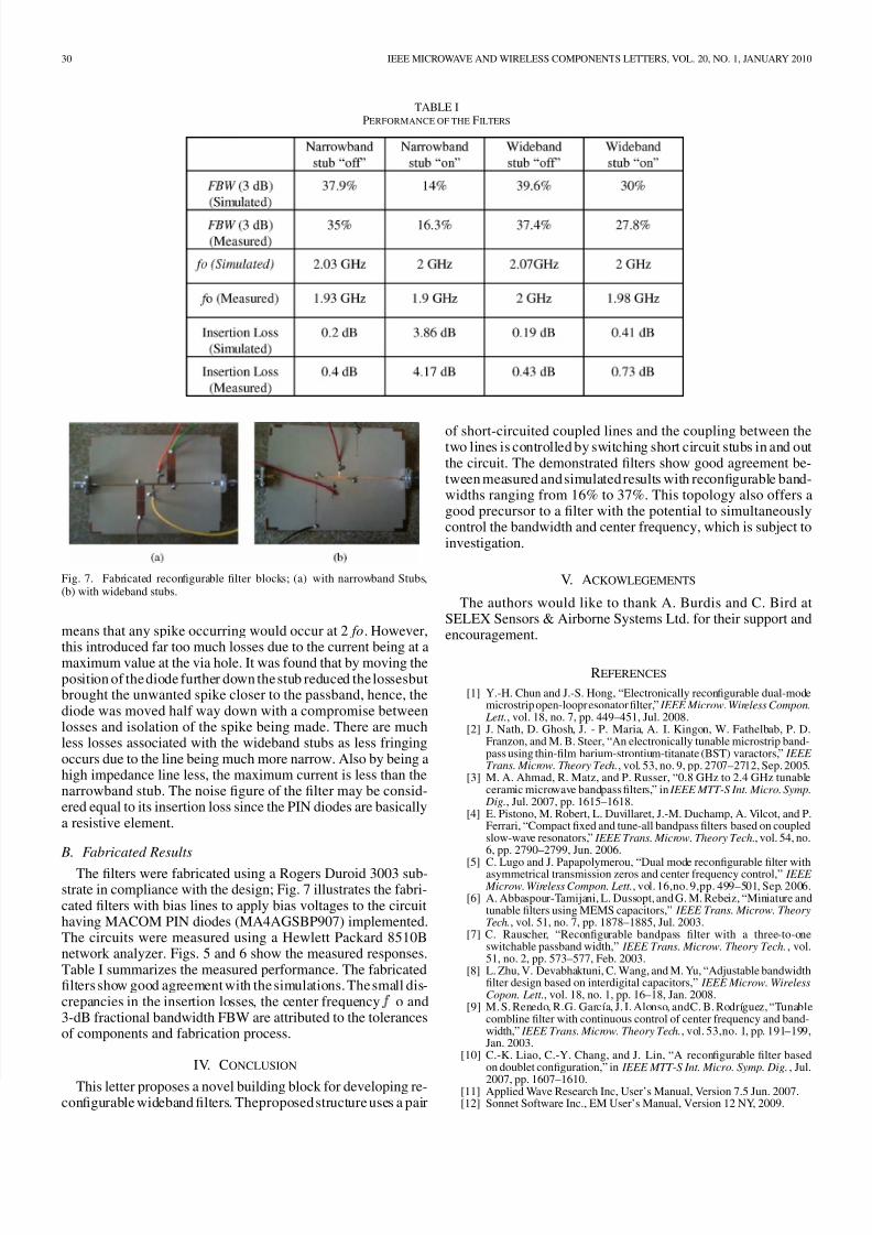
Fig. 7. Fabricated reconfigurable filter blocks; (a) with narrowband Stubs,(b) with wideband stubs.
means that any spike occurring would occur at 2 fo. However,
this introduced far too much losses due to the current being at amaximum value at the via hole. It was found that by moving theposition of the diode further down the stub reduced the lossesbutbrought the unwanted spike closer to the passband, hence, thediode was moved half way down with a compromise betweenlosses and isolation of the spike being made. There are muchless losses associated with the wideband stubs as less fringingoccurs due to the line being much more narrow. Also by being ahigh impedance line less, the maximum current is less than thenarrowband stub. The noise figure of the filter may be consid-ered equal to its insertion loss since the PIN diodes are basicallya resistive element.
B. Fabricated Results
The filters were fabricated using a Rogers Duroid 3003 sub-strate in compliance with the design; Fig. 7 illustrates the fabri-cated filters with bias lines to apply bias voltages to the circuithaving MACOM PIN diodes (MA4AGSBP907) implemented.The circuits were measured using a Hewlett Packard 8510Bnetwork analyzer. Figs. 5 and 6 show the measured responses.Table I summarizes the measured performance. The fabricatedfilters show good agreement with the simulations. The small dis-crepancies in the insertion losses, the center frequency o and3-dB fractional bandwidth FBW are attributed to the tolerancesof components and fabrication process.
IV. CONCLUSION
This letter proposes a novel building block for developing re-configurable wideband filters. Theproposed structure uses a pair
of short-circuited coupled lines and the coupling between thetwo lines is controlled by switching short circuit stubs in and outthe circuit. The demonstrated filters show good agreement be-tween measured and simulated results with reconfigurable band-widths ranging from 16% to 37%. This topology also offers agood precursor to a filter with the potential to simultaneouslycontrol the bandwidth and center frequency, which is subject toinvestigation.
V. ACKOWLEGEMENTS
The authors would like to thank A. Burdis and C. Bird atSELEX Sensors & Airborne Systems Ltd. for their support andencouragement.
REFERENCES
[1] Y.-H. Chun and J.-S. Hong, “Electronically reconfigurable dual-modemicrostrip open-loopresonator filter,” IEEE Microw. Wireless Compon.
Lett., vol. 18, no. 7, pp. 449–451, Jul. 2008.[2] J. Nath, D. Ghosh, J. - P. Maria, A. I. Kingon, W. Fathelbab, P. D.
Franzon, and M. B. Steer, “An electronically tunable microstrip band-pass using thin-film barium-strontium-titanate (BST) varactors,” IEEE Trans. Microw. Theory Tech., vol. 53, no. 9, pp. 2707–2712, Sep. 2005.
[3] M. A. Ahmad, R. Matz, and P. Russer, “0.8 GHz to 2.4 GHz tunableceramic microwave bandpass filters,” in IEEE MTT-S Int. Micro. Symp.
Dig., Jul. 2007, pp. 1615–1618.[4] E. Pistono, M. Robert, L. Duvillaret, J.-M. Duchamp, A. Vilcot, and P.
Ferrari, “Compact fixed and tune-all bandpass filters based on coupledslow-wave resonators,” IEEE Trans. Microw. Theory Tech., vol. 54, no.6, pp. 2790–2799, Jun. 2006.
[5] C. Lugo and J. Papapolymerou, “Dual mode reconfigurable filter withasymmetrical transmission zeros and center frequency control,” IEEE Microw. Wireless Compon. Lett., vol. 16,no. 9,pp. 499–501, Sep. 2006.
[6] A. Abbaspour-Tamijani, L. Dussopt, and G. M. Rebeiz, “Miniature andtunable filters using MEMS capacitors,” IEEE Trans. Microw. TheoryTech., vol. 51, no. 7, pp. 1878–1885, Jul. 2003.
[7] C. Rauscher, “Reconfigurable bandpass filter with a three-to-oneswitchable passband width,” IEEE Trans. Microw. Theory Tech., vol.51, no. 2, pp. 573–577, Feb. 2003.
[8] L. Zhu, V. Devabhaktuni, C. Wang, and M. Yu, “Adjustable bandwidthfilter design based on interdigital capacitors,” IEEE Microw. WirelessCopon. Lett., vol. 18, no. 1, pp. 16–18, Jan. 2008.
[9] M. S. Renedo, R.G. García, J. I. Alonso, andC. B. Rodríguez, “Tunablecombline filter with continuous control of center frequency and band-width,” IEEE Trans. Microw. Theory Tech., vol. 53,no. 1, pp. 191–199,Jan. 2003.
[10] C.-K. Liao, C.-Y. Chang, and J. Lin, “A reconfigurable filter basedon doublet configuration,” in IEEE MTT-S Int. Micro. Symp. Dig. , Jul.
2007, pp. 1607–1610.[11] Applied Wave Research Inc, User’s Manual, Version 7.5 Jun. 2007.[12] Sonnet Software Inc., EM User’s Manual, Version 12 NY, 2009.
AlultIXDoM1a1UfIX Ra