WIDE RANGE SCANNING RECEIVER DJ-X2000 - QRZCQ · The Alinco DJ-X2000 is a professional...
88
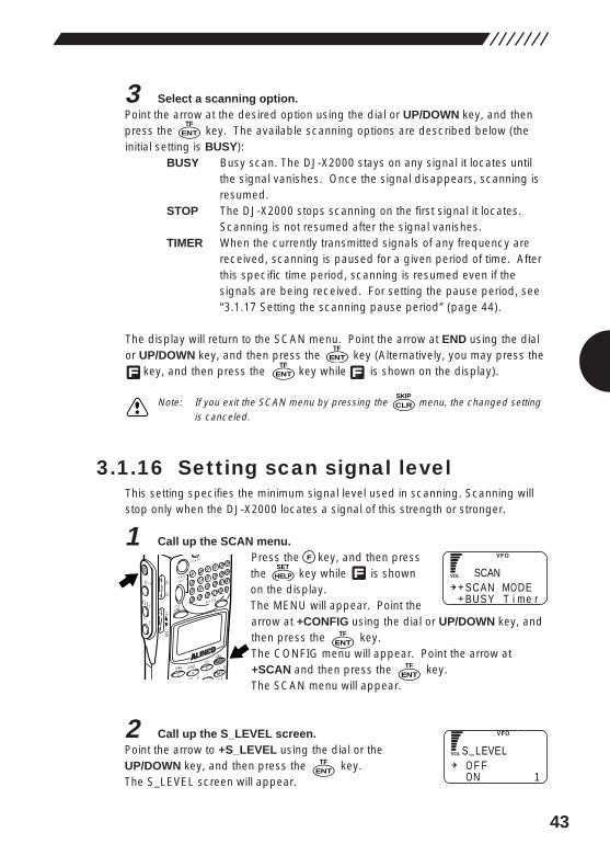
DJ-X2000 WIDE RANGE SCANNING RECEIVER Instruction Manual MODE AUTO MW INTELLIGENT RECEIVER DJ-X2 MIC SCRT PRIO REC CTCSS F TUNE A B S M NAME TF SKIP STEP ATT SET POWER RX/ST PMS VFO MR MW A B SET KL 3 6 9 8 0 5 2 1 4 CLR ENT MIC SCN RF C HELP 7 MONI F SRCH LAMP S Q L V O L D O W N U P CLN S P Thank you for purchasing this ALINCO receiver.The DJ-X2000 instruction manual contains important safety and operating instructions. Read this manual carefully before using the product.
Transcript of WIDE RANGE SCANNING RECEIVER DJ-X2000 - QRZCQ · The Alinco DJ-X2000 is a professional...
DJ-X2000WIDE RANGE SCANNING RECEIVER
Instruction Manual
MODE
AUTO MW
INTELLIGENT
RECEIVERDJ-X2
MIC
SCRTPRIO
REC
CTCSS
F TUNE
A-B S
M NAME
TF
SKIP
STEPATT
SET
POWER
RX/ST
PMS
VFOMR MW
A B
SET
KL
�3
6
98
0
5
21
4
CLR
ENT
MIC
SCN
RF C
HELP
7
MONI
F
SRCH
LAMP
SQL VOL
DOWN U P
CLNS P
Thank you for purchasing this ALINCO receiver.The DJ-X2000 instruction manual contains important safety and operating instructions. Read this manual carefully before using the product.
1
FeaturesThe Alinco DJ-X2000 is a professional multifunctional receiver which covers awide band of radio media from the low-frequency band (LF) to ultrahigh-frequency (UHF) band. It has the following features:
1. Wide frequency range The DJ-X2000 covers a wide frequency range from 0.1to 2149.999950 MHz.
2. Three operating modes The DJ-X2000 has three basic operating modes: DualVFO, Memory (MR), and Scan Programming (PMS).The modes can be switched by one-touch operation.
3. LARGE Memory capacity Memory function allows you to program up to 2000channels. (40 ch × 50 banks)
4. Scanning Various kinds of scanning are available: Program scan(PMS), Memory scan, Mode-select scan, VFO scan,VFO-linked scan, and Priority scan.
5. 20 scan programs The PMS mode has a total of 20 programmable bands.
6. Channel Scope™ The search function checks frequencies in setfrequency steps and displays signals within a 40-channel or 7-channel range at one time.
7. Battery-save function The battery-save function automatically saves batterypower whenever keys are not used or a signal is notpicked up for a certain amount of time.
8. Cloning You can copy the settings stored in memory from oneDJ-X2000 to another. Moreover, you can connect theDJ-X2000 to a personal computer and copy thesettings.
9. All mode reception You can select a modulation mode from AM, NFM,WFM, LSB, USB, CW, and AUTO. When AUTO isselected, the DJ-X2000 automatically determines themost suitable modulation mode for the currentlyreceived frequency.
10. Channel step Channel step is selectable from 23 fixed steps, or youcan choose any step between 50 Hz - 500 kHz. Inaddition, the DJ-X2000 determines the most suitablechannel step for the currently received frequency whenAUTO is selected.
2
11. Frequency editing You can copy the content of one memory channel toanother, or rename memory channels.
12. Transweeper™ The DJ-X2000 detects a listening microphone whichtransmits a radio wave from a hidden transmitter. If alistening microphone is found, the DJ-X2000 will alertyou with a display and warning sound.
13. Recording function The DJ-X2000 records the sound of a currentlyreceived signal or sound from the microphone, andreplays it. The maximum recording time is 160seconds.
14. Descrambler The DJ-X2000 can return scrambled voice transmissionto normal voice reception.
15. Flash tune If there are signals around the DJ-X2000, it tunes to thestrongest frequency in a flash.
16. RF checker This function allows you to use the DJ-X2000 as a radiofrequency counter.
17. Electric field strength meter The DJ-X2000 can measure relative electric fieldstrength and indicate it on the display.
18. Directional microphone The built-in microphone picks up sound and amplifies it.
19. Receives FM radio in stereo The DJ-X2000 receives stereo FM when stereo
headphones are used.
20. CTCSS decoder The DJ-X2000 decodes CTCSS tones.
21. A/B squelch This function cancels the squelch when there is nomodulation signal of 2300Hz.
22. Help-navigator The Help-navigator displays how to use each functionof the DJ-X2000. Moreover, you can jump to setting thecurrently displayed function from the help menu, andexecute the function.
23. Exceedingly sensitive antenna for HF and MFNewly developed antenna is included.
24. DC switching power supply DC switching power supply conserves battery power.
25. 2-level attenuator High (20 dB) and Low (10 dB) attenuators areincluded.
3
ContentsFeatures …………………………………………………………1
Contents …………………………………………………………3
How to read this manual ………………………………………6
1. Before use ……………………………………………………71.1 Unpacking the receiver…………………………………………………71.2 Precautions in use ………………………………………………………71.3 Names of parts and their functions …………………………………8
1.3.1 Top, front and left side panels……………………………………………………………8
1.3.2 Rear and right panels……………………………………………………………………10
1.3.3 Display ……………………………………………………………………………………11
1.3.4 Key pad……………………………………………………………………………………12
1.4 Setting up the DJ-X2000………………………………………………131.4.1 Attaching the antenna……………………………………………………………………13
1.4.2 Attaching the belt clip……………………………………………………………………13
1.4.3 Attaching the wrist strap…………………………………………………………………13
1.5 About the batteries ……………………………………………………141.5.1 Attaching the battery pack………………………………………………………………14
1.5.2 About the battery pack …………………………………………………………………15
1.5.3 Ni-Cd battery charger……………………………………………………………………16
1.5.4 Battery low alarm…………………………………………………………………………18
2. Basic operations……………………………………………192.1 POWER switch …………………………………………………………192.2 Volume control …………………………………………………………192.3 Squelch control…………………………………………………………202.4 Setting frequency………………………………………………………202.5 Switching frequency band……………………………………………222.6 Copying frequencies from one band to the other ………………222.7 Scanning…………………………………………………………………222.8 Searching(Channel Scope™) ………………………………………232.9 Monitoring(Squelch OFF) ……………………………………………242.10 Turning backlight ON/OFF …………………………………………25
2.10.1 Turning backlight ON/OFF manually …………………………………………………25
2.10.2 Turning backlight ON/OFF based on the setting……………………………………25
4
2.11 Turning beep ON/OFF ………………………………………………262.12 Locking/Unlocking……………………………………………………272.13 Setting the clock………………………………………………………27
2.13.1 Setting the OFF timer…………………………………………………………………27
2.13.2 Setting the ON timer …………………………………………………………………28
2.14 Basic modes …………………………………………………………292.14.1 VFO mode ………………………………………………………………………………29
2.14.2 PMS mode ………………………………………………………………………………30
2.14.3 MR mode…………………………………………………………………………………30
2.15 Using HELP menu …………………………………………………31
3. Other Useful Functions……………………………………323.1 Functions common to all modes ……………………………………32
3.1.1 Selecting a modulation mode …………………………………………………………32
3.1.2 Setting the frequency step………………………………………………………………32
3.1.3 Attenuating interference from other channels(ATT) …………………………………33
3.1.4 Battery Save………………………………………………………………………………34
3.1.5 Copying data between two receivers(CLONE) ………………………………………35
3.1.6 Selecting a communication speed ……………………………………………………36
3.1.7 Selecting a language mode ……………………………………………………………37
3.1.8 Field-strength meter ……………………………………………………………………37
3.1.9 Displaying battery voltage………………………………………………………………39
3.1.10 Setting the reception tone ……………………………………………………………39
3.1.11 Selecting the BELL mode………………………………………………………………40
3.1.12 Changing the initial message …………………………………………………………40
3.1.13 Resetting the receiver …………………………………………………………………41
3.1.14 Tuning in frequencies in the PMS/MR modes(M.TUNE)……………………………42
3.1.15 Setting scan resume condition(SCAN MODE)………………………………………42
3.1.16 Setting scan signal level ………………………………………………………………43
3.1.17 Setting the scanning pause period …………………………………………………44
3.1.18 Turning the priority function ON/OFF…………………………………………………45
3.1.19 Selecting a priority option ……………………………………………………………45
3.1.20 Setting a priority channel………………………………………………………………46
3.1.21 Specifying a priority interval …………………………………………………………47
3.1.22 Setting search resume condition(SRCH MODE)……………………………………48
3.1.23 Flash tune ………………………………………………………………………………49
3.1.24 Descrambler ……………………………………………………………………………51
3.1.25 CTCSS decoding function ……………………………………………………………52
5
3.1.26 A/B squelch ……………………………………………………………………………54
3.1.27 Transweeper™ …………………………………………………………………………55
3.1.28 Recording function ……………………………………………………………………57
3.1.29 Sound pickup……………………………………………………………………………59
3.1.30 Directly changing the settings…………………………………………………………60
3.2 Functions in the VFO mode ………………………………………613.2.1 VFO link function …………………………………………………………………………61
3.2.2 Scanning between VFO's A and B(AB SCAN) ………………………………………62
3.2.3 Copying frequencies from memories to the VFO ……………………………………62
3.2.4 Copying frequencies from the PMS mode to the VFO ………………………………63
3.3 PMS mode functions …………………………………………………643.3.1 Programmed scan operations …………………………………………………………64
3.3.2 Setting scan pass-frequency……………………………………………………………65
3.3.3 Setting program link ……………………………………………………………………66
3.3.4 Copying scan programs…………………………………………………………………66
3.3.5 Moving a scanning program……………………………………………………………67
3.3.6 Deleting scan programs…………………………………………………………………68
3.4 MR mode functions ……………………………………………………693.4.1 Memorizing frequencies…………………………………………………………………69
3.4.2 Setting the auto memory write function ………………………………………………70
3.4.3 Setting memory scan skip ………………………………………………………………70
3.4.4 Setting memory scan radio system(MODE SEL) ……………………………………71
3.4.5 Using the Bank Link function……………………………………………………………72
3.4.6 Selecting memory channels for scanning ……………………………………………72
3.4.7 Scanning the memory channels selected in the PMR screen………………………74
3.4.8 Copying memory banks…………………………………………………………………74
3.4.9 Copying memory channels ……………………………………………………………75
3.4.10 Moving a memory bank ………………………………………………………………76
3.4.11 Moving a memory channel ……………………………………………………………77
3.4.12 Deleting memory banks ………………………………………………………………79
3.4.13 Deleting and restoring memory channels………………………………………………80
3.4.14 Searching for a memory tag …………………………………………………………81
4.Appendix………………………………………………………824.1 Specifications …………………………………………………………824.2 Troubleshooting ………………………………………………………834.3 Optional items …………………………………………………………834.4 List of Help menu items ………………………………………………84
6
How to read this manualThe following typographical and graphic conventions are used in this instructionmanual.
Bold typeface indicates titles of chapters and sections as well as messagesshown on the display.When used to indicate displayed messages, only the part of the message that ispertinent to the explanation is given. Actual messages may however containmore characters.
Plain typeface text enclosed in “ ” indicates sections in this instruction manualyou should refer to for further information. Only in a few cases are quotationmarks used to identify terminology.
Note: The note icon contains additional information pertinent to product use, whichis helpful but not necessarily known.
CAUTION: The caution icon contains information which, if ignored or notfollowed correctly, could result in product damage. Always read andobserve these items.
7
1. Before use1.1 Unpacking the receiver
The DJ-X2000 should come with the following accessories. Check that nothing ismissing when you first open the package.
• Antenna (EA-94) × 1• Charger (EDC-88) × 1• Ni-Cd battery pack (EBP-37N) × 1• Belt clip with two screws (EBC-3) × 1• Wrist strap × 1• DJ-X2000 Instruction Manual (This manual) × 1
Standard accessories may differ depending on the version.
1.2 Precautions in use• Do not use or store the receiver in dusty places, where exposed to direct
sunlight, near sources of heat, or in other adverse environments.• Attach the included antenna securely to the receiver.• Use only the EDC-36 car lighter cable (with active filter) to draw power from an
automobile.• If the receiver emits smoke or strange odors, shut power OFF immediately and
promptly contact an authorized dealer.• Do not disassemble or tamper with the receiver. The DJ-X2000 is not warranted
for troubles or accidents resulting from unauthorized modifications, regardlessof the warranty period. Alinco dealer also reserves the right to refuse to servicethe receiver in such event.
• Obtain approval from the proper authorities before using this receiver on boardaircraft or in hospitals.
• Do not use 9.6 V or higher voltage batteries (e.g. EBP-36N).
8
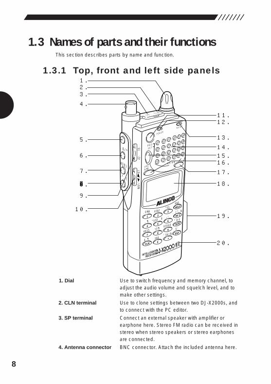
1.3 Names of parts and their functionsThis section describes parts by name and function.
1.3.1 Top, front and left side panels
1. Dial Use to switch frequency and memory channel, toadjust the audio volume and squelch level, and tomake other settings.
2. CLN terminal Use to clone settings between two DJ-X2000s, andto connect with the PC editor.
3. SP terminal Connect an external speaker with amplifier orearphone here. Stereo FM radio can be received instereo when stereo speakers or stereo earphonesare connected.
4. Antenna connector BNC connector. Attach the included antenna here.
1.2.3.4.
5.
6.
�
9.
8.
7.
10.
11.12.
13.14.15.16.17.
18.
19.
20.
MODE
AUTO MW
INTELLIGENT
RECEIVERDJ-X2
MIC
SCRTPRIO
REC
CTCSS
F TUNE
A-B S
M NAME
TF
SKIP
STEPATT
SET
POWER
RX/ST
PMS
VFOMR MW
A B
SET
KL
�3
6
98
0
5
21
4
CLR
ENT
MIC
SCN
RF C
HELP
7
MONI
F
SRCH
LAMP
SQL VOL
DOWN UP
CLNS P
9
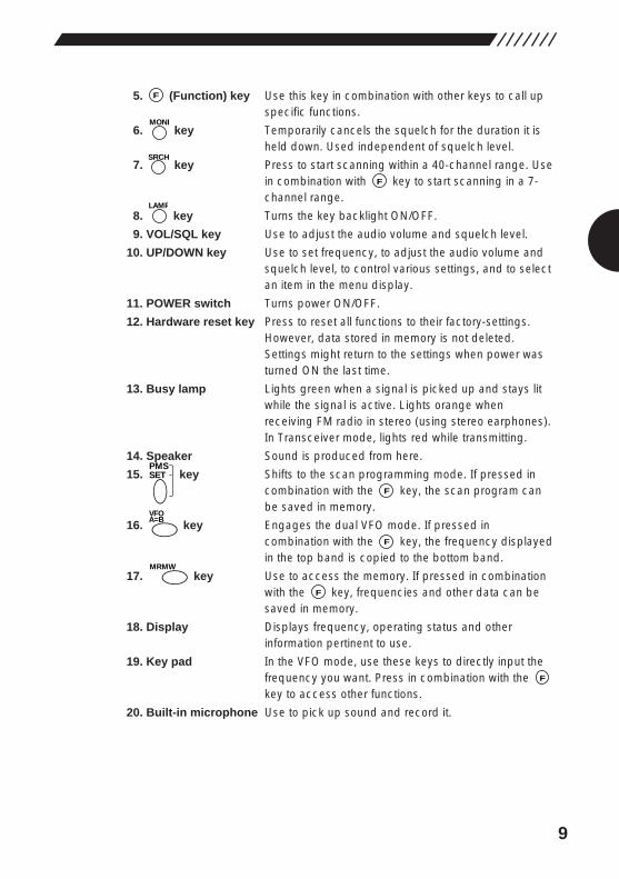
5. (Function) key Use this key in combination with other keys to call upspecific functions.
6. key Temporarily cancels the squelch for the duration it isheld down. Used independent of squelch level.
7. key Press to start scanning within a 40-channel range. Usein combination with key to start scanning in a 7-channel range.
8. key Turns the key backlight ON/OFF.
9. VOL/SQL key Use to adjust the audio volume and squelch level.
10. UP/DOWN key Use to set frequency, to adjust the audio volume andsquelch level, to control various settings, and to selectan item in the menu display.
11. POWER switch Turns power ON/OFF.
12. Hardware reset key Press to reset all functions to their factory-settings.However, data stored in memory is not deleted.Settings might return to the settings when power wasturned ON the last time.
13. Busy lamp Lights green when a signal is picked up and stays litwhile the signal is active. Lights orange whenreceiving FM radio in stereo (using stereo earphones).In Transceiver mode, lights red while transmitting.
14. Speaker Sound is produced from here.
15. key Shifts to the scan programming mode. If pressed incombination with the key, the scan program canbe saved in memory.
16. key Engages the dual VFO mode. If pressed incombination with the key, the frequency displayedin the top band is copied to the bottom band.
17. key Use to access the memory. If pressed in combinationwith the key, frequencies and other data can besaved in memory.
18. Display Displays frequency, operating status and otherinformation pertinent to use.
19. Key pad In the VFO mode, use these keys to directly input thefrequency you want. Press in combination with the key to access other functions.
20. Built-in microphone Use to pick up sound and record it.
F
F
MRMW
F
A=BVFO
F
PMSSET
LAMP
F
SRCH
MONI
F
10
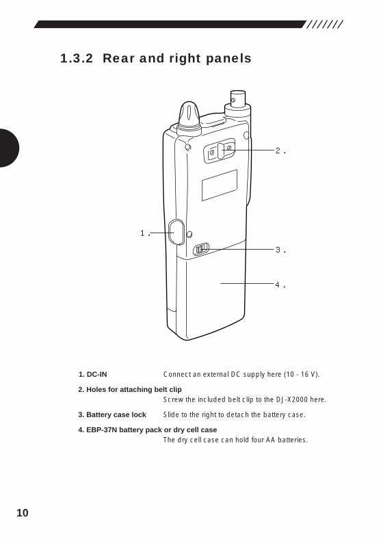
1.3.2 Rear and right panels
1. DC-IN Connect an external DC supply here (10 - 16 V).
2. Holes for attaching belt clipScrew the included belt clip to the DJ-X2000 here.
3. Battery case lock Slide to the right to detach the battery case.
4. EBP-37N battery pack or dry cell caseThe dry cell case can hold four AA batteries.
1.
2.
3.
4.
11
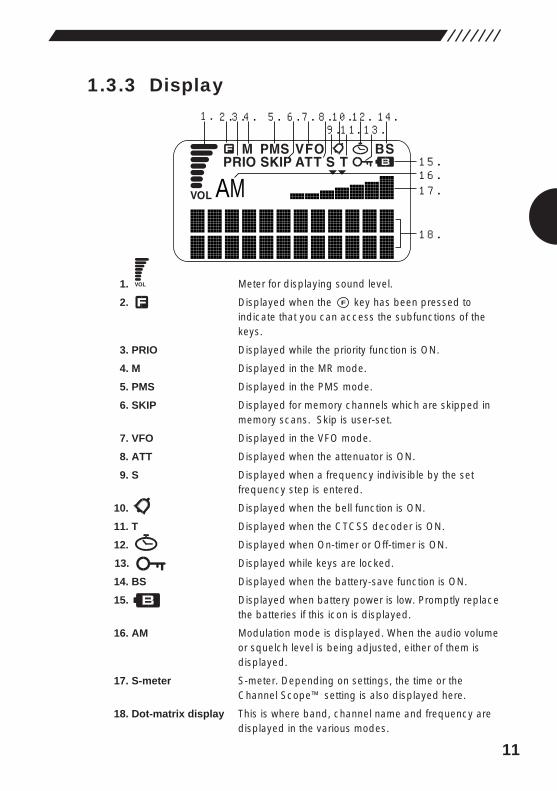
1.3.3 Display
1. Meter for displaying sound level.
2. Displayed when the key has been pressed toindicate that you can access the subfunctions of thekeys.
3. PRIO Displayed while the priority function is ON.
4. M Displayed in the MR mode.
5. PMS Displayed in the PMS mode.
6. SKIP Displayed for memory channels which are skipped inmemory scans. Skip is user-set.
7. VFO Displayed in the VFO mode.
8. ATT Displayed when the attenuator is ON.
9. S Displayed when a frequency indivisible by the setfrequency step is entered.
10. Displayed when the bell function is ON.
11. T Displayed when the CTCSS decoder is ON.
12. Displayed when On-timer or Off-timer is ON.
13. Displayed while keys are locked.
14. BS Displayed when the battery-save function is ON.
15. Displayed when battery power is low. Promptly replacethe batteries if this icon is displayed.
16. AM Modulation mode is displayed. When the audio volumeor squelch level is being adjusted, either of them isdisplayed.
17. S-meter S-meter. Depending on settings, the time or theChannel Scope™ setting is also displayed here.
18. Dot-matrix display This is where band, channel name and frequency aredisplayed in the various modes.
F
AM
1.
18.
2.3.4. 5. 6. 7. 8.9.10.12.11. 13.
14.
15.
17.16.
12
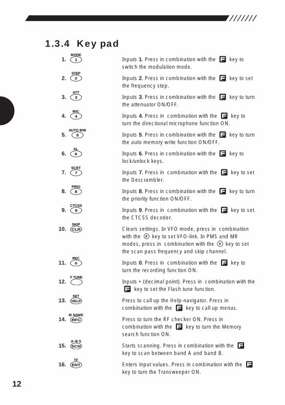
1.3.4 Key pad1. Inputs 1. Press in combination with the key to
switch the modulation mode.
2. Inputs 2. Press in combination with the key to setthe frequency step.
3. Inputs 3. Press in combination with the key to turnthe attenuator ON/OFF.
4. Inputs 4. Press in combination with the key toturn the directional microphone function ON.
5. Inputs 5. Press in combination with the key to turnthe auto memory write function ON/OFF.
6. Inputs 6. Press in combination with the key tolock/unlock keys.
7. Inputs 7. Press in combination with the key to setthe Descrambler.
8. Inputs 8. Press in combination with the key to turnthe priority function ON/OFF.
9. Inputs 9. Press in combination with the key to setthe CTCSS decoder.
10. Clears settings. In VFO mode, press in combinationwith the key to set VFO-link. In PMS and MRmodes, press in combination with the key to setthe scan pass frequency and skip channel.
11. Inputs 0. Press in combination with the key toturn the recording function ON.
12. Inputs • (decimal point). Press in combination with thekey to set the Flash tune function.
13. Press to call up the Help-navigator. Press incombination with the key to call up menus.
14. Press to turn the RF checker ON. Press incombination with the key to turn the Memorysearch function ON.
15. Starts scanning. Press in combination with the key to scan between band A and band B.
16. Enters input values. Press in combination with the key to turn the Transweeper ON.
ENTTF
SCNA~B S
RFCM NAME
HELPSET
F TUNE
0REC
F
F
CLRSKIP
9CTCSS
8PRIO
7SCRT
6KL
5AUTO MW
4MIC
3ATT
2STEP
1MODE
13
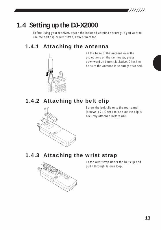
1.4 Setting up the DJ-X2000Before using your receiver, attach the included antenna securely. If you want touse the belt clip or wrist strap, attach them too.
1.4.1 Attaching the antennaFit the base of the antenna over theprojections on the connector, pressdownward and turn clockwise. Check tobe sure the antenna is securely attached.
1.4.2 Attaching the belt clipScrew the belt clip onto the rear panel(screws x 2). Check to be sure the clip issecurely attached before use.
1.4.3 Attaching the wrist strapFit the wrist strap under the belt clip andpull it through its own loop.
POWER
RX/ST
PMS
VFOMR MW
A B
SETMONI
F
SRCH
SQL VOL
P
CLNS P
14
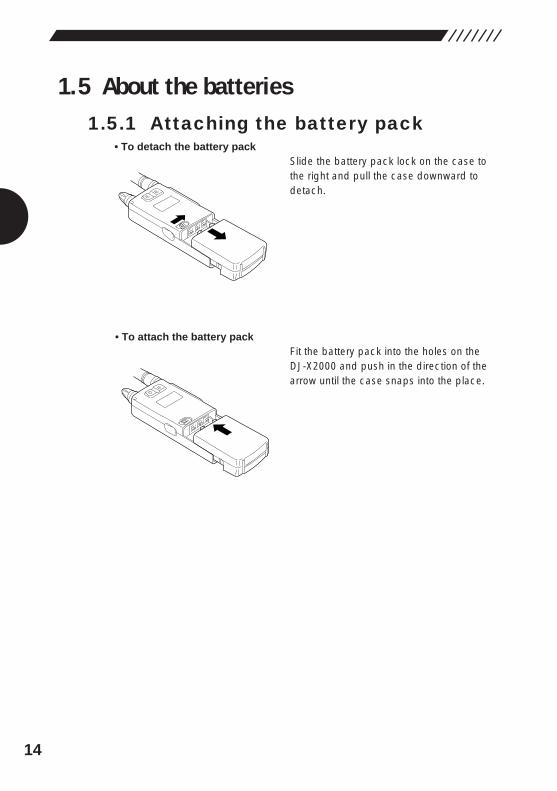
1.5 About the batteries1.5.1 Attaching the battery pack
• To detach the battery packSlide the battery pack lock on the case tothe right and pull the case downward todetach.
• To attach the battery packFit the battery pack into the holes on the DJ-X2000 and push in the direction of thearrow until the case snaps into the place.
15
1.5.2 About the battery packBefore using the included EBP-37N battery pack, please note the following:
1. The battery pack is not charged before it is shipped from the factory. Chargethe pack before using the DJ-X2000 for the first time.
2. Approximately 1 hour is required to fully charge the battery pack with thecharger.
3. Charge batteries only in temperatures from 0°C to 40°C (32°F~104°F).4. DANGER! Do not disassemble, tamper with, heat or wet the battery pack. 5. Do not short-circuit battery pack terminals. This can generate heat inside the
pack resulting in burns and/or damage to the pack.6. Do not overcharge the battery pack. Overcharging can lead to battery
performance loss.7. Store the battery pack in a cool, dry place where temperature is between
-20°C and 45°C(-4°F~113°F). Environments outside this range can causebattery acid to leak and metal parts to rust.
8. The battery pack can be fully recharged approximately 300 times. When afully charged battery pack lasts considerably less than expected, it is time toreplace it with a fresh pack.
9. Do not throw away dead Ni-Cd battery packs. They can be recycled. Givethem to stores which accept old batteries.
10. Do not charge an unexhausted battery pack repeatedly. It may shorten theoperating time of a battery pack.
• To prevent battery pack short-circuiting When carrying the battery pack, be extremely careful not to short-circuit theterminals. If short-circuited, the high surge in current could heat up the pack,resulting in burns or fire.
1. Keep the battery pack away from metal objects such as necklaces, etc.2. Do not keep the battery pack inside bags with metal-plated linings or wrap it in
handkerchiefs with metallic thread or print.3. Do not leave the battery pack in proximity of electro-conductive materials or
metal objects such as nails or chains.4. Place the battery pack in an electrically-insulated bag or wrap it in a
handkerchief before putting it in your handbag, etc.5. Place the battery pack on an electrically-insulated mat when setting it on a flat
surface.
16
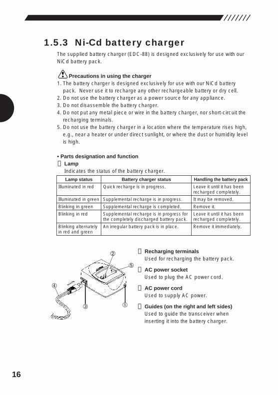
1.5.3 Ni-Cd battery chargerThe supplied battery charger (EDC-88) is designed exclusively for use with ourNiCd battery pack.
Precautions in using the charger1. The battery charger is designed exclusively for use with our NiCd battery
pack. Never use it to recharge any other rechargeable battery or dry cell.2. Do not use the battery charger as a power source for any appliance.3. Do not disassemble the battery charger.4. Do not put any metal piece or wire in the battery charger, nor short-circuit the
recharging terminals.5. Do not use the battery charger in a location where the temperature rises high,
e.g., near a heater or under direct sunlight, or where the dust or humidity levelis high.
• Parts designation and function
➀ LampIndicates the status of the battery charger.
➁ Recharging terminalsUsed for recharging the battery pack.
➂ AC power socketUsed to plug the AC power cord.
➃ AC power cordUsed to supply AC power.
➄ Guides (on the right and left sides)Used to guide the transceiver wheninserting it into the battery charger.
Lamp status
Illuminated in red
Illuminated in green
Blinking in green
Blinking in red
Blinking alternately in red and green
Battery charger status
Quick recharge is in progress.
Supplemental recharge is in progress.
Supplemental recharge is completed.
Supplemental recharge is in progress for the completely discharged battery pack.
An irregular battery pack is in place.
Handling the battery pack
Leave it until it has been recharged completely.
It may be removed.
Remove it.
Leave it until it has been recharged completely.
Remove it immediately.
17
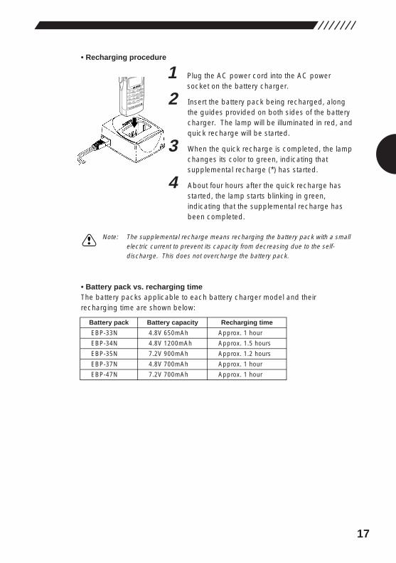
• Recharging procedure
1 Plug the AC power cord into the AC powersocket on the battery charger.
2 Insert the battery pack being recharged, alongthe guides provided on both sides of the batterycharger. The lamp will be illuminated in red, andquick recharge will be started.
3 When the quick recharge is completed, the lampchanges its color to green, indicating thatsupplemental recharge (*) has started.
4 About four hours after the quick recharge hasstarted, the lamp starts blinking in green,indicating that the supplemental recharge hasbeen completed.
Note: The supplemental recharge means recharging the battery pack with a smallelectric current to prevent its capacity from decreasing due to the self-discharge. This does not overcharge the battery pack.
• Battery pack vs. recharging timeThe battery packs applicable to each battery charger model and theirrecharging time are shown below:
MODE
AUTO MW
INTELLIGENT
RECEIVERDJ-X2
MIC
SCRTPRIO
REC
CTCSS
F TUNE
A-B S
M NAME
TF
SKIP
STEPATT
SET
KL
�3
6
98
0
5
21
4
CLR
ENT
MIC
SCN
RF C
HELP
7
LAMP
DOWN
Battery pack
EBP-33N
EBP-34N
EBP-35N
EBP-37N
EBP-47N
Battery capacity
4.8V 650mAh
4.8V 1200mAh
7.2V 900mAh
4.8V 700mAh
7.2V 700mAh
Recharging time
Approx. 1 hour
Approx. 1.5 hours
Approx. 1.2 hours
Approx. 1 hour
Approx. 1 hour
18
Precautions in recharging1. Ensure that the transceiver is OFF when recharging the battery pack. The use
of the transceiver during recharging can cause the transceiver to malfunction.2. The battery charger is designed to be used at an ambient temperature
between 10°C and 40°C (50°F and 104°F). Avoid recharging the battery packat any temperature outside this range.
3. Do not repeatedly recharge a fully recharged battery pack. This can causethe performance of the battery pack to deteriorate. The battery pack can berecharged up to 300 times when it is used normally. If the life of thecompletely recharged battery pack becomes markedly shorter, the batterypack is considered to have been exhausted. Please purchase a new batterypack.
4. Do not insert the battery pack in a reverse direction.5. When the battery pack has been recharged completely, with the lamp blinking
green, remove the battery pack from the battery charger.6. If the battery charger is not used for a long period of time, disconnect the AC
power cord from the wall socket, and remove the battery pack from the batterycharger.
7. If you recharge a battery pack of which voltage has abnormally dropped dueto discharge, the lamp starts blinking red and a preliminary recharge initiatesimmediately after you have started recharging the battery pack.Subsequently, the lamp will be illuminated red, indicating that the quickrecharge has started.
8. If any irregular battery pack is set in place, the lamp will blink alternately in redand green.
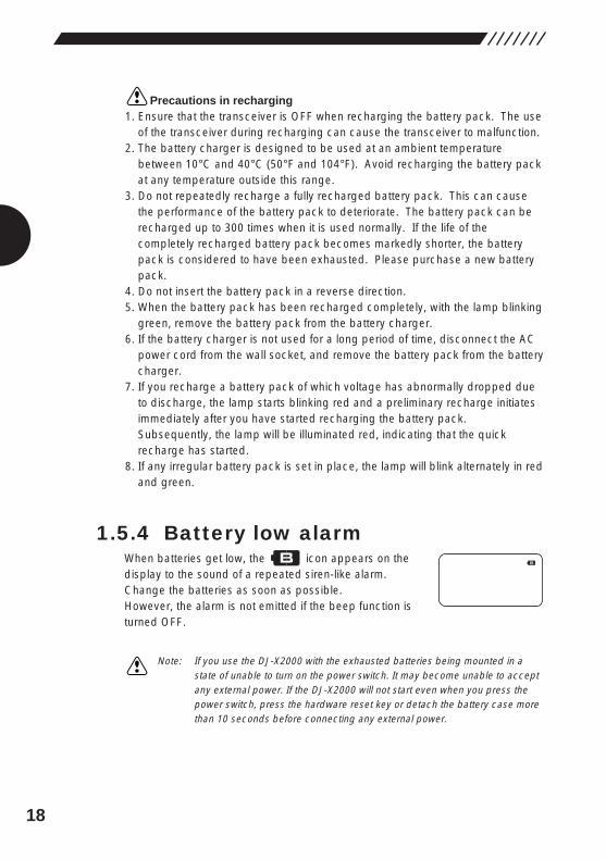
1.5.4 Battery low alarmWhen batteries get low, the icon appears on thedisplay to the sound of a repeated siren-like alarm.Change the batteries as soon as possible. However, the alarm is not emitted if the beep function isturned OFF.
Note: If you use the DJ-X2000 with the exhausted batteries being mounted in astate of unable to turn on the power switch. It may become unable to acceptany external power. If the DJ-X2000 will not start even when you press thepower switch, press the hardware reset key or detach the battery case morethan 10 seconds before connecting any external power.
19
2. Basic operationsThis chapter describes the basic operations for the DJ-X2000.
2.1 POWER switchTo turn ON/OFF the DJ-X2000, perform the following operation:
• Turning ONHold down the POWER switch for approx. 1 second untilthe message “ALINCO INTELLIGENT RECEIVER™”appears on the display.
• Turning OFFHold down the POWER switch until the display goes out.
Note: The message that appears on the display may be changed (see “3.1.12Changing the initial message” on page 40).
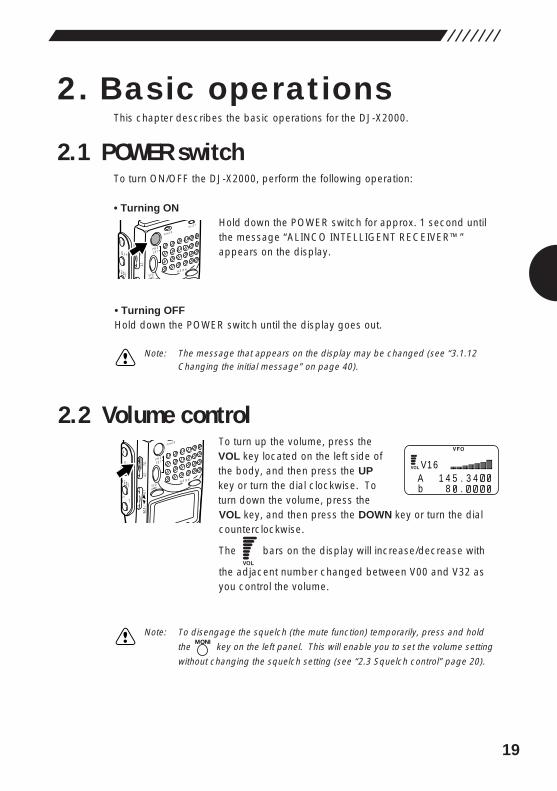
2.2 Volume controlTo turn up the volume, press theVOL key located on the left side ofthe body, and then press the UPkey or turn the dial clockwise. Toturn down the volume, press theVOL key, and then press the DOWN key or turn the dialcounterclockwise.
The bars on the display will increase/decrease with
the adjacent number changed between V00 and V32 asyou control the volume.
Note: To disengage the squelch (the mute function) temporarily, press and hold
the key on the left panel. This will enable you to set the volume setting
without changing the squelch setting (see “2.3 Squelch control” page 20).
MONI
POWER
PMS
VFOMR MW
A B
SETMONI
F
SRCH
LAMP
SQL VOL
DOWN UP
POWER
RX/ST
PMS
VFOMR MW
A B
SETMONI
F
SRCH
SQL VOL
P
VA 1 4 5 . 3 4b 8 .
1 6
20
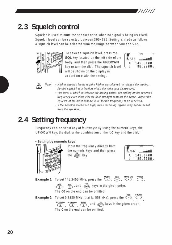
2.3 Squelch controlSquelch is used to mute the speaker noise when no signal is being received.Squelch level can be selected between S00~S32. Setting is made as follows.A squelch level can be selected from the range between S00 and S32.
To select a squelch level, press theSQL key located on the left side of thebody, and then press the UP/DOWNkey or turn the dial. The squelch levelwill be shown on the display inaccordance with the setting.
Note: • Higher squelch levels require higher signal levels to release the muting.Set the squelch to a level at which the noise just disappears.
• The level at which to release the muting varies depending on the receivedfrequency even if the electric field strength remains the same. Adjust thesquelch at the most suitable level for the frequency to be received.
• If the squelch level is too high, weak incoming signals may not be heardfrom the speaker.
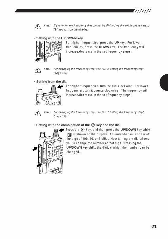
2.4 Setting frequencyFrequency can be set in any of four ways: By using the numeric keys, theUP/DOWN key, the dial, or the combination of the key and the dial.
• Setting by numeric keysInput the frequency directly fromthe numeric keys and then pressthe key.
Example 1 To set 145.3400 MHz, press the , , , ,
, , and keys in the given order.
The 00 on the end can be omitted.
Example 2 To set 0.5580 MHz (that is, 558 kHz), press the , ,
, , , and keys in the given order.
The 0 on the end can be omitted.
ENTTF
8PRIO
5AUTO MW
5AUTO MW
F TUNE0
REC
ENTTF
4MIC
3ATT
F TUNE5
AUTO MW
4MIC
1MODE
ENTTF
MODE
AUTO MW
INTELLIGENT
RECEIVERDJ-X2
MIC
SCRTPRIO
REC
CTCSS
F TUNE
A-B S
M NAME
TF
SKIP
STEPATT
SET
KL
�3
6
98
0
5
21
4
CLR
ENT
MIC
SCN
RF C
HELP
7
DO
F
PMS
VFOMR MW
A B
SETMONI
F
SRCH
LAMP
SQL VOL
DOWN UP
SA 1 4 5 . 3 4b 8 .
5
NA 1 4 5 . 3 4b 8 .
FM
21
Note: If you enter any frequency that cannot be divided by the set frequency step,“S” appears on the display.
• Setting with the UP/DOWN keyFor higher frequencies, press the UP key. For lowerfrequencies, press the DOWN key. The frequency willincrease/decrease in the set frequency steps.
Note: For changing the frequency step, see “3.1.2 Setting the frequency step”(page 32).
• Setting from the dialFor higher frequencies, turn the dial clockwise. For lowerfrequencies, turn it counterclockwise. The frequency willincrease/decrease in the set frequency steps.
Note: For changing the frequency step, see “3.1.2 Setting the frequency step”(page 32).
• Setting with the combination of the key and the dialPress the key, and then press the UP/DOWN key while
is shown on the display. An under-bar will appear atthe digit of 100, 10, or 1 MHz. Now turning the dial allowsyou to change the number at that digit. Pressing theUP/DOWN key shifts the digit at which the number can bechanged.
F
MODE M NAMESTEP
ATTSET
POWER
RX/ST
PMS
VFOMR MW
A B
SET
�3
HELP
MONI
F
SRCH
LAMP
SQL VOL
DOWN UP
CLNS P
F
POWER
RX/ST
SF
CLNS P
PMS
VFOMR MW
A B
SETMONI
F
SRCH
LAMP
SQL VOL
DOWN UP
22
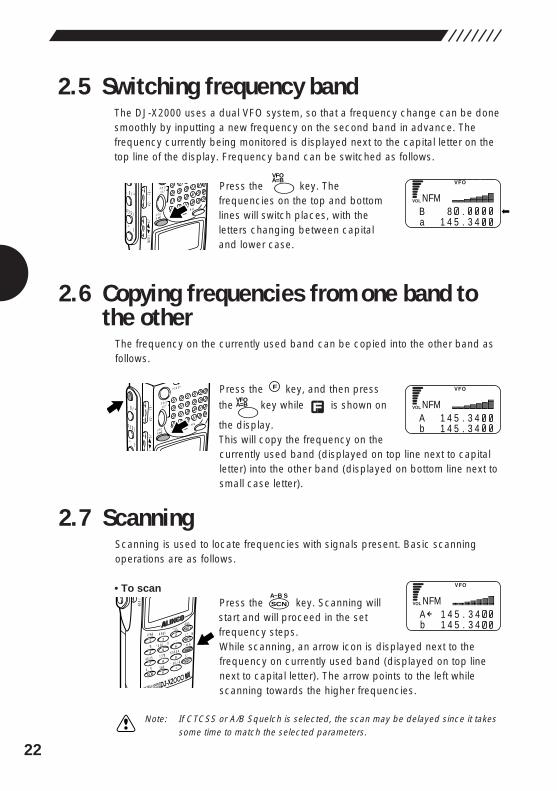
2.5 Switching frequency bandThe DJ-X2000 uses a dual VFO system, so that a frequency change can be donesmoothly by inputting a new frequency on the second band in advance. Thefrequency currently being monitored is displayed next to the capital letter on thetop line of the display. Frequency band can be switched as follows.
Press the key. Thefrequencies on the top and bottomlines will switch places, with theletters changing between capitaland lower case.
2.6 Copying frequencies from one band tothe other
The frequency on the currently used band can be copied into the other band asfollows.
Press the key, and then press
the key while is shown on
the display. This will copy the frequency on thecurrently used band (displayed on top line next to capitalletter) into the other band (displayed on bottom line next tosmall case letter).
2.7 ScanningScanning is used to locate frequencies with signals present. Basic scanningoperations are as follows.
• To scanPress the key. Scanning willstart and will proceed in the setfrequency steps.While scanning, an arrow icon is displayed next to thefrequency on currently used band (displayed on top linenext to capital letter). The arrow points to the left whilescanning towards the higher frequencies.
Note: If CTCSS or A/B Squelch is selected, the scan may be delayed since it takessome time to match the selected parameters.
SCNA~B S
MODE
AUTO MW
INTELLIGENTCEIVERDJ-X2
MIC
SCRTPRIO
REC
CTCSS
F TUNE
A-B S
M NAME
TF
SKIP
STEPATT
SET
KL
�3
6
98
0
5
21
4
CLR
ENT
MIC
SCN
RF C
HELP
7
P
DOWN
A=BVFO
FPOWER
PMS
VFOMR MW
A B
SETMONI
F
SRCH
LAMP
SQL VOL
WN UP
A=BVFO
PMS
VFOMR MW
A B
SETMONI
F
SRCH
LAMP
SQL VOL
DOWN UP
NB 8 .a 1 4 5 . 3 4
FM
NA 1 4 5 . 3 4b 1 4 5 . 3 4
FM
NA 1 4 5 . 3 4b 1 4 5 . 3 4
FM
23
If live frequencies are received, scanning is temporarily stopped. To resumescanning, turn the dial or press the UP/DOWN key. Scanning can beautomatically resumed by specifying scan resuming conditions. For furtherdetails, see “3.1.15 Setting scan resume condition (SCAN MODE)” (page 42).
• To switch scanning directionWhile scanning, press the DOWN key. The arrow icon will face right andscanning will proceed toward the lower frequencies. To scan toward the higherfrequencies, press the UP key. The scanning direction can also be changed byturning the dial.
• To cancel scanning
Press the key again.
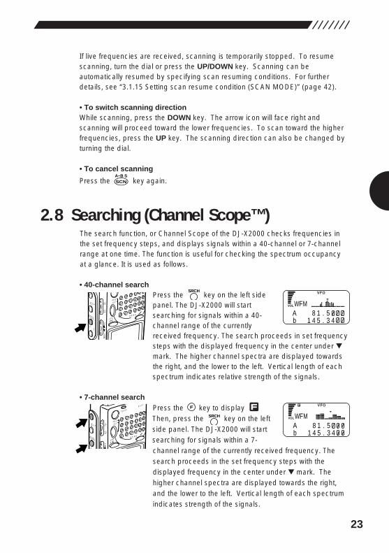
2.8 Searching (Channel Scope™)The search function, or Channel Scope of the DJ-X2000 checks frequencies inthe set frequency steps, and displays signals within a 40-channel or 7-channelrange at one time. The function is useful for checking the spectrum occupancyat a glance. It is used as follows.
• 40-channel searchPress the key on the left sidepanel. The DJ-X2000 will startsearching for signals within a 40-channel range of the currentlyreceived frequency. The search proceeds in set frequencysteps with the displayed frequency in the center under ▼mark. The higher channel spectra are displayed towardsthe right, and the lower to the left. Vertical length of eachspectrum indicates relative strength of the signals.
• 7-channel searchPress the key to display Then, press the key on the leftside panel. The DJ-X2000 will startsearching for signals within a 7-channel range of the currently received frequency. Thesearch proceeds in the set frequency steps with thedisplayed frequency in the center under ▼ mark. Thehigher channel spectra are displayed towards the right,and the lower to the left. Vertical length of each spectrumindicates strength of the signals.
SRCH
FPOWE
R
RX/ST
PMS
VFOMR MW
A B
SETMONI
F
SRCH
LAMP
SQL VOL
UP
SRCH
PMS
VFOMR MW
A B
SETMONI
F
SRCH
LAMP
SQL VOL
DOWN UP
SCNA~B S
WA 8 1 . 5b 1 4 5 . 3 4
FM
WA 8 1 . 5b 1 4 5 . 3 4
FM
24
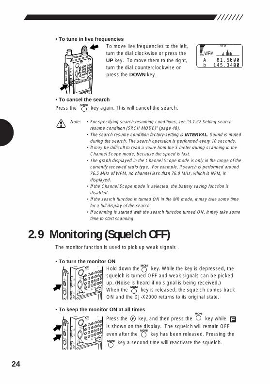
• To tune in live frequenciesTo move live frequencies to the left,turn the dial clockwise or press theUP key. To move them to the right,turn the dial counterclockwise orpress the DOWN key.
• To cancel the search
Press the key again. This will cancel the search.
Note: • For specifying search resuming conditions, see “3.1.22 Setting searchresume condition (SRCH MODE)” (page 48).
• The search resume condition factory-setting is INTERVAL. Sound is mutedduring the search. The search operation is performed every 10 seconds.
• It may be difficult to read a value from the S meter during scanning in theChannel Scope mode, because the speed is fast.
• The graph displayed in the Channel Scope mode is only in the range of thecurrently received radio type. For example, if search is performed around76.5 MHz of WFM, no channel less than 76.0 MHz, which is NFM, isdisplayed.
• If the Channel Scope mode is selected, the battery saving function isdisabled.
• If the search function is turned ON in the MR mode, it may take some timefor a full display of the search.
• If scanning is started with the search function turned ON, it may take sometime to start scanning.
2.9 Monitoring (Squelch OFF)The monitor function is used to pick up weak signals .
• To turn the monitor ONHold down the key. While the key is depressed, thesquelch is turned OFF and weak signals can be pickedup. (Noise is heard if no signal is being received.)When the key is released, the squelch comes backON and the DJ-X2000 returns to its original state.
• To keep the monitor ON at all times
Press the key, and then press the key while
is shown on the display. The squelch will remain OFF
even after the key has been released. Pressing the
key a second time will reactivate the squelch.MONI
MONI
MONI
FPOWE
R
RX/ST
PMS
VFOMR MW
A B
SETMONI
F
SRCH
LAMP
SQL VOL
N UP
MONI
MONIPOWE
R
RX/ST
PMS
VFOMR MW
A B
SETMONI
F
SRCH
LAMP
SQL VOL
N UP
SRCH
SET
POWER
RX/ST
PMS
VFOMR MW
A B
SETMONI
F
SRCH
LAMP
SQL VOL
DOWN UP
CLNS PW
A 8 1 . 5b 1 4 5 . 3 4
FM
25
2.10 Turning backlight ON/OFFThe DJ-X2000 has a backlight to make it easier to use at night. The backlight canbe turned ON/OFF as follows.
2.10.1 Turning backlight ON/OFFmanually
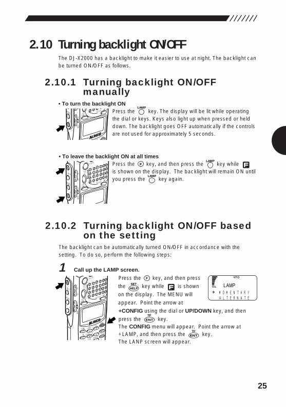
• To turn the backlight ONPress the key. The display will be lit while operatingthe dial or keys. Keys also light up when pressed or helddown. The backlight goes OFF automatically if the controlsare not used for approximately 5 seconds.
• To leave the backlight ON at all timesPress the key, and then press the key while is shown on the display. The backlight will remain ON untilyou press the key again.
2.10.2 Turning backlight ON/OFF basedon the setting
The backlight can be automatically turned ON/OFF in accordance with thesetting. To do so, perform the following steps:
1 Call up the LAMP screen.
Press the key, and then press
the key while is shown
on the display. The MENU will
appear. Point the arrow at
+CONFIG using the dial or UP/DOWN key, and then
press the key.The CONFIG menu will appear. Point the arrow at+LAMP, and then press the key.The LANP screen will appear.
ENTTF
ENTTF
HELPSET
F
MODE
AUTO MW
MIC
SCRTPRIO
CTCSSA-B S
M NAME
TF
STEPATT
SET
POWER
PMS
VFOMR MW
A B
SET
KL
�3
6
9
5
21
4SCN
RF C
HELP
MONI
F
SRCH
LAMP
SQL VOL
DOWN UP
LAMP
LAMPFPOWE
R
PMS
VFOMR MW
A B
SETMONI
F
SRCH
LAMP
SQL VOL
DOWN UP
LAMP
ATTSET
VFOMR MW
A B
HELP
SRCH
LAMP
SDOWN UP
M O M E N T A R YA L T E R N A T E
LAMP
26
2 Select a backlight mode as follows:Using the dial or UP/DOWN key, point the arrow at a desired mode, and thenpress the key (the initial setting is the MOMENTARY mode).
AUTO: The backlight is lit for 5 seconds after the dial or key isused.
MOMENTARY: The backlight remains lit only while the key is beingheld down.
ALTERNATE: The backlight is turned alternately ON and OFF every timethe key is pressed.
The display will go back to the CONFIG menu. Point the arrow at END, and then press the key (or alternatively, press the key, and then press the
key with shown on the display.
Note: If you exit the CONFIG menu by pressing the key, the changedsetting is canceled.
2.11 Turning beep ON/OFFThe beep sound that is emitted when a key is pressed or a specific operation isperformed can be turned ON/OFF and its volume can be controlled as follows:
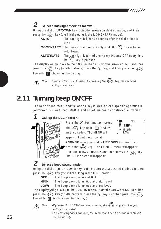
1 Call up the BEEP screen.
Press the key, and then press
the key while is shown
on the display. The MENU will
appear. Point the arrow at
+CONFIG using the dial or UP/DOWN key, and then
press the key. The CONFIG menu will appear.
Point the arrow at +BEEP, and then press the key.The BEEP screen will appear.
2 Select a beep sound mode.Using the dial or the UP/DOWN key, point the arrow at a desired mode, and thenpress the key (the initial setting is the HIGH mode).
OFF: The beep sound is turned OFF.HIGH: The beep sound is emitted at a high level.LOW: The beep sound is emitted at a low level.
The display will go back to the CONFIG menu. Point the arrow at END, and thenpress the key (or alternatively, press the key, and then press the key while is shown on the display.).
Note: •If you exit the CONFIG menu by pressing the key, the changedsetting is canceled.
• If stereo earphones are used, the beep sound can be heard from the leftearphone only.
CLRSKIP
ENTTF
FENTTF
ENTTF
ENTTF
ENTTF
HELPSET
F
MODE
AUTO MW
MIC
SCRTPRIO
CTCSSA-B S
M NAME
TF
STEPATT
SET
POWER
PMS
VFOMR MW
A B
SET
KL
�3
6
9
5
21
4SCN
RF C
HELP
MONI
F
SRCH
LAMP
SQL VOL
DOWN UP
CLRSKIP
ENTTF
FENTTF
LAMP
LAMP
ENTTF
H i g hL OW
BEEP
27
2.12 Locking/UnlockingThis feature locks all but certain keys, preventing accidental operation of thekeys. Keys can be locked/unlocked as follows.
• To lock keysPress the key, and then press
the key while is shown
on the display.will appear on the display
and the keys will be locked except for the POWERswitch, dial, and , VOL/SQL, UP/DOWN, , and
keys.
• To unlock keysAgain, press the key, and then press the key while is shown onthe display. This will unlock the keys.
2.13 Setting the clockThis section describes the ON and OFF timers that allows you to automaticallyturn the power ON/OFF.The ON timer allows you to set the time that will be taken until the power isautomatically turned ON. The OFF timer allows you to set the time that will betaken until the power is automatically turned OFF.Since the timers for the DJ-X2000 use a 24-hour system, the power isautomatically turned ON/OFF in accordance with the time settings every day.
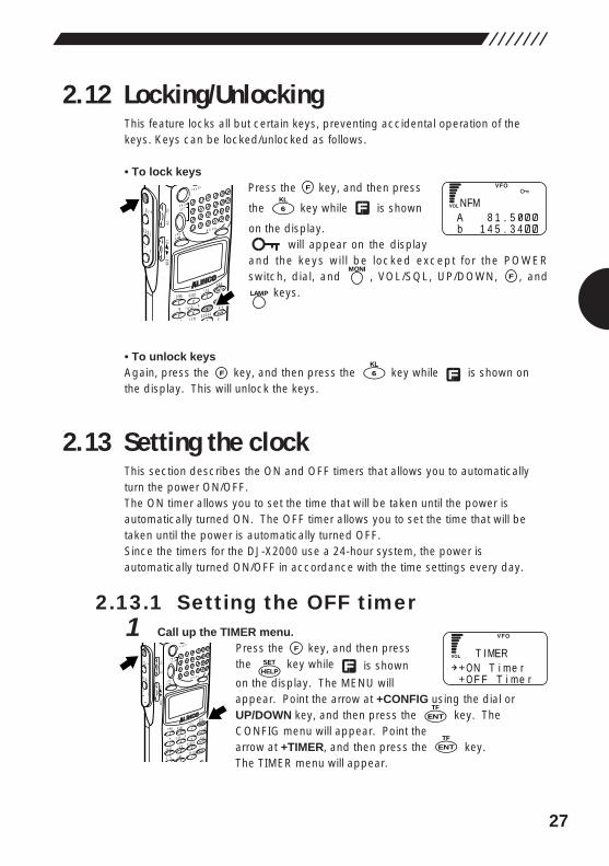
2.13.1 Setting the OFF timer1 Call up the TIMER menu.
Press the key, and then press the key while is shown
on the display. The MENU willappear. Point the arrow at +CONFIG using the dial orUP/DOWN key, and then press the key. TheCONFIG menu will appear. Point the arrow at +TIMER, and then press the key.The TIMER menu will appear.
ENTTF
ENTTF
HELPSET
F
MODE
AUTO MW
MIC
SCRTPRIO
REC
CTCSS
F TUNE
A-B S
M NAME
TF
SKIP
STEPATT
SET
POWER
PMS
VFOMR MW
A B
SET
KL
�3
6
98
0
5
21
4
CLR
ENT
SCN
RF C
HELP
7
MONI
F
SRCH
LAMP
SQL VOL
DOWN UP
6KL
F
LAMP
FMONI
6KL
F
MODE
AUTO MW
MIC
SCRTPRIO
CTCSSA-B S
M NAME
TF
STEPATT
SET
POWER
PMS
VFOMR MW
A B
SET
KL
�3
6
9
5
21
4SCN
RF C
HELP
MONI
F
SRCH
LAMP
SQL VOL
DOWN UP
NA 8 1 . 5b 1 4 5 . 3 4
FM
ON T i me rO F F T i me r
T I MER
28
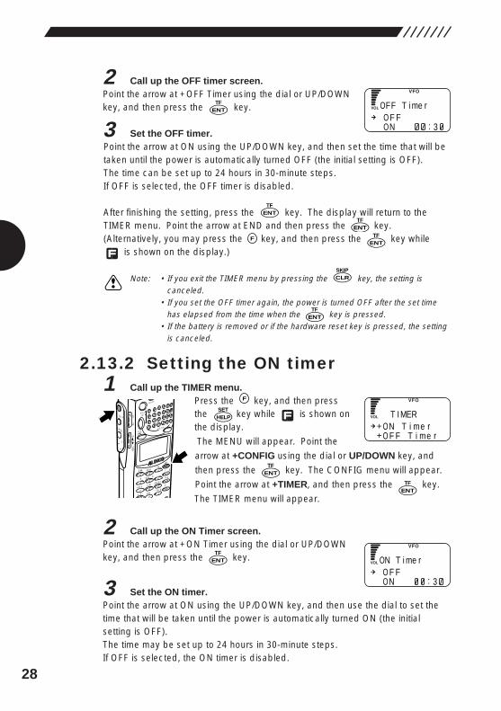
2 Call up the OFF timer screen.Point the arrow at +OFF Timer using the dial or UP/DOWNkey, and then press the key.
3 Set the OFF timer.Point the arrow at ON using the UP/DOWN key, and then set the time that will betaken until the power is automatically turned OFF (the initial setting is OFF).The time can be set up to 24 hours in 30-minute steps.If OFF is selected, the OFF timer is disabled.
After finishing the setting, press the key. The display will return to the TIMER menu. Point the arrow at END and then press the key.(Alternatively, you may press the key, and then press the key while
is shown on the display.)
Note: • If you exit the TIMER menu by pressing the key, the setting iscanceled.
• If you set the OFF timer again, the power is turned OFF after the set timehas elapsed from the time when the key is pressed.
• If the battery is removed or if the hardware reset key is pressed, the settingis canceled.
2.13.2 Setting the ON timer1 Call up the TIMER menu.
Press the key, and then pressthe key while is shown onthe display.
The MENU will appear. Point the
arrow at +CONFIG using the dial or UP/DOWN key, and
then press the key. The CONFIG menu will appear.
Point the arrow at +TIMER, and then press the key.
The TIMER menu will appear.
2 Call up the ON Timer screen.Point the arrow at +ON Timer using the dial or UP/DOWNkey, and then press the key.
3 Set the ON timer.Point the arrow at ON using the UP/DOWN key, and then use the dial to set thetime that will be taken until the power is automatically turned ON (the initialsetting is OFF).The time may be set up to 24 hours in 30-minute steps.If OFF is selected, the ON timer is disabled.
ENTTF
ENTTF
ENTTF
HELPSET
F
MODE
AUTO MW
MIC
SCRTPRIO
REC
CTCSS
F TUNE
A-B S
M NAME
TF
SKIP
STEPATT
SET
POWER
PMS
VFOMR MW
A B
SET
KL
�3
6
98
0
5
21
4
CLR
ENT
SCN
RF C
HELP
7
MONI
F
SRCH
LAMP
SQL VOL
DOWN UP
ENTTF
CLRSKIP
ENTTF
F
ENTTF
ENTTF
:O F FON 3
FFO T i me r
ON T i me rO F F T i me r
T I MER
O F FON 3:
NO T i me r
ENTTF
29
After finishing the setting, press the key. The display will return to the
TIMER menu. Point the arrow at END and then press the key.
(Alternatively, you may press the key, and then press the key while
is shown on the display.)
Note: • If you exit the TIMER menu by pressing the key, the setting iscanceled.
• If you set the ON timer again, the power is turned ON after the set time haselapsed from the time when the key is pressed.
• If the battery is removed or if the hardware reset key is pressed, the settingis canceled.
2.14 Basic modesThe DJ-X2000 has three basic modes: VFO, PMS, and MR. The current mode isdisplayed along the top of the display.
• VFO modeThis mode is used to select a frequency with the dial or UP/DOWN key and thenreceive signals at that frequency. The VFO mode was selected at factory.
• PMS (programmed scan-range) modeThis mode is for tuning in selected channels within a set scan range.
• MR (memory) modeThis mode is for saving often used frequencies in memory. The frequencies canthen be retrieved and tuned in.
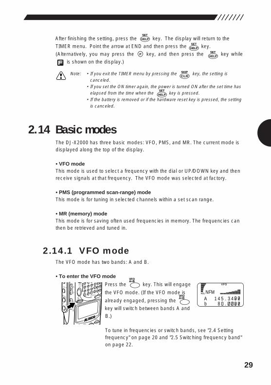
2.14.1 VFO modeThe VFO mode has two bands: A and B.
• To enter the VFO mode
Press the key. This will engage
the VFO mode. (If the VFO mode is
already engaged, pressing the
key will switch between bands A and
B.)
To tune in frequencies or switch bands, see "2.4 Settingfrequency" on page 20 and "2.5 Switching frequency band"on page 22.
A=BVFO
A=BVFO
MODE M NAMESTEP
ATTSET
PMS
VFOMR MW
A B
SET
�3
HELP
MONI
F
SRCH
LAMP
SQL VOL
DOWN UP
HELPSET
CLRSKIP
HELPSET
F
HELPSET
NA 1 4 5 . 3 4b 8 .
FM
HELPSET
30
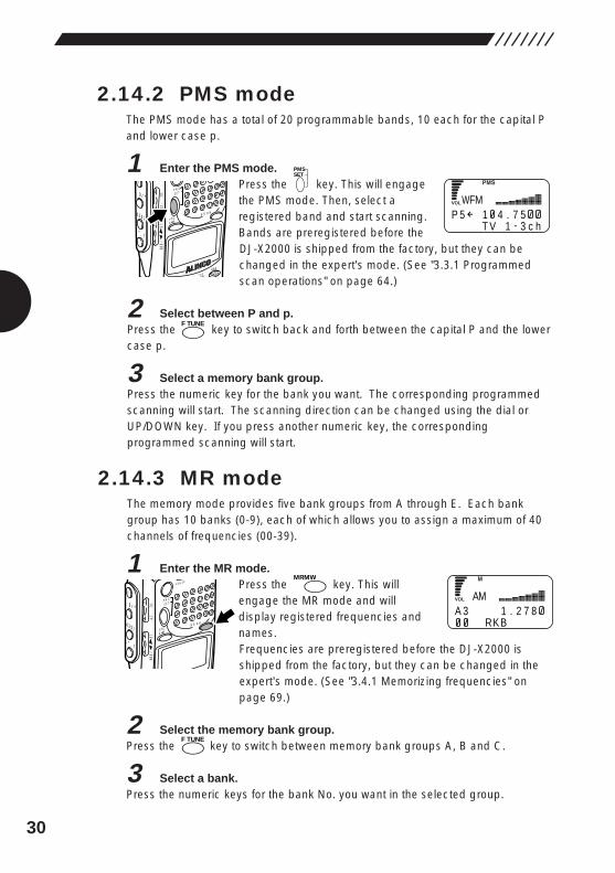
2.14.2 PMS modeThe PMS mode has a total of 20 programmable bands, 10 each for the capital Pand lower case p.
1 Enter the PMS mode.Press the key. This will engagethe PMS mode. Then, select aregistered band and start scanning.Bands are preregistered before theDJ-X2000 is shipped from the factory, but they can bechanged in the expert's mode. (See "3.3.1 Programmedscan operations" on page 64.)
2 Select between P and p.Press the key to switch back and forth between the capital P and the lowercase p.
3 Select a memory bank group.Press the numeric key for the bank you want. The corresponding programmedscanning will start. The scanning direction can be changed using the dial orUP/DOWN key. If you press another numeric key, the correspondingprogrammed scanning will start.
2.14.3 MR modeThe memory mode provides five bank groups from A through E. Each bankgroup has 10 banks (0-9), each of which allows you to assign a maximum of 40channels of frequencies (00-39).
1 Enter the MR mode.Press the key. This willengage the MR mode and willdisplay registered frequencies andnames.Frequencies are preregistered before the DJ-X2000 isshipped from the factory, but they can be changed in theexpert's mode. (See "3.4.1 Memorizing frequencies" onpage 69.)
2 Select the memory bank group.Press the key to switch between memory bank groups A, B and C.
3 Select a bank.Press the numeric keys for the bank No. you want in the selected group.
F TUNE
MRMWPOWE
R
PMS
VFOMR MW
A B
SETMONI
F
SRCH
LAMP
SQL VOL
DOWN UP
F TUNE
PMSSET
E MESTEPATT
SET
PMS
VFOMR MW
A B
SET
�HELP
MONI
F
SRCH
LAMP
SQL VOL
DOWN UP
WP 5 1 4 . 7 5
T V 1 - 3 c h
FM
A 3 1 . 2 7 8RK B
AM
31
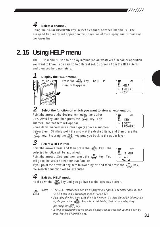
4 Select a channel.Using the dial or UP/DOWN key, select a channel between 00 and 39. Theassigned frequency will appear on the upper line of the display and its name onthe lower line.
2.15 Using HELP menuThe HELP menu is used to display information on whatever function or operationyou want to know. You can go to different setup screens from the HELP itemsand then set the parameters.
1 Display the HELP menu.Press the key. The HELPmenu will appear.
2 Select the function on which you want to view an explanation.Point the arrow at the desired item using the dial orUP/DOWN key, and then press the key. Thesubmenu for that item will appear.Some items marked with a plus sign (+) have a submenubelow them. Similarly point the arrow at the desired item, and then press the
key. Pressing the key puts you back to the upper layer.
3 Select a HELP item.Point the arrow at Inst. and then press the key. Theselected function will be explained.Point the arrow at Set! and then press the key. Youwill go to the setup screen for that function.If you point the arrow at any item followed by “!” and then press the key,the selected function will be executed.
4 Exit the HELP mode.Hold down the key until you go back to the previous screen.
Note: • The HELP information can be displayed in English. For further details, see“3.1.7 Selecting a language mode” (page 37).
• Selecting the Set! item exits the HELP mode. To view the HELP informationagain, press the key after establishing Set! or canceling it by
pressing the key.• A long explanation shown on the display can be scrolled up and down by
pressing the UP/DOWN key.
ENTTF
CLRSKIP
ENTTF
ENTTF
ENTTF
ENTTF
HELPSET
MODE
AUTO MW
MIC
SCRTPRIO
CTCSS
NE
A-B S
M NAME
TF
STEPATT
SET
VFOMR MW
A B
KL
�3
6
9
5
21
4
T
SCN
RF C
HELP
SRCH
LAMP
DOWN UP
CLRSKIP
HE L PK E Y
HELP
S E TP OWER
KEY
I n s t .S e t
T I MER
CLRSKIP
ENTTF
32
3. Other Useful FunctionsThis chapter describes the useful functions of the DJ-X2000.
3.1 Functions common to all modesThis section describes the functions that are commonly available in the VFO,PMS, and MR modes.
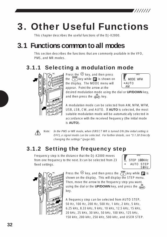
3.1.1 Selecting a modulation modePress the key, and then pressthe key while is shown onthe display. The MODE menu willappear. Point the arrow at thedesired modulation mode using the dial or UP/DOWN key,and then press the key.
A modulation mode can be selected from AM, NFM, WFM,USB, LSB, CW, and AUTO. If AUTO is selected, the mostsuitable modulation mode will be automatically selected inaccordance with the received frequency (the initial modeis AUTO).
Note: In the PMS or MR mode, when DIRECT WR is turned ON (the initial setting isOFF), a signal mode can be selected. For further details, see “3.1.30 Directlychanging the settings” (page 60).
3.1.2 Setting the frequency stepFrequency step is the distance that the DJ-X2000 movesfrom one frequency to the next. It can be selected from 23fixed settings.
Press the key, and then press the key while isshown on the display. This will display the STEP menu.Then, move the arrow to the frequency step you want,using the dial or the UP/DOWN key, and press the key.
A frequency step can be selected from AUTO STEP,50 Hz, 100 Hz, 200 Hz, 500 Hz, 1 kHz, 2 kHz, 5 kHz,6.25 kHz, 8.33 kHz, 9 kHz, 10 kHz, 12.5 kHz, 15 kHz,20 kHz, 25 kHz, 30 kHz, 50 kHz, 100 kHz, 125 kHz,150 kHz, 200 kHz, 250 kHz, 500 kHz, and USER STEP.
ENTTF
2STEPF
MODE
AUTO MW
MIC
SCRTPRIO
REC
CTCSS
F TUNE
A-B S
M NAME
TF
SKIP
STEPATT
SET
POWER
PMS
VFOMR MW
A B
SET
KL
�3
6
98
0
5
21
4
LR
ENT
SCN
RF C
HELP
7
MONI
F
SRCH
LAMP
SQL VOL
DOWN UP
ENTTF
1MODE
F
MODE
AUTO MW
MIC
SCRTPRIO
REC
CTCSS
F TUNE
A-B S
M NAME
TF
SKIP
STEPATT
SET
POWER
PMS
VFOMR MW
A B
SET
KL
�3
6
98
0
5
21
4
R
ENT
SCN
RF C
HELP
7
MONI
F
SRCH
LAMP
SQL VOL
DOWN UP
AU T OAM
MODE WFM
AU T O S T E P5 H z
STEP 1 KHz
33
Note: In the PMS or MR mode, setting DIRECT WR to ON enables selection of afrequency step and modulation mode and adjustment of the attenuator andCTCSS decoders. For further details, see “3.1.30 Directly changing thesettings” (page 60).
If AUTO STEP is selected, the most suitable frequency step for the receivedfrequency band will be automatically selected.If USER STEP is selected, a frequency step can be selected freely in a rangebetween 50 Hz and 499.95 kHz.
Example: To enter 150 kHz, press: , , , , To enter 450 kHz, press: , , , ,
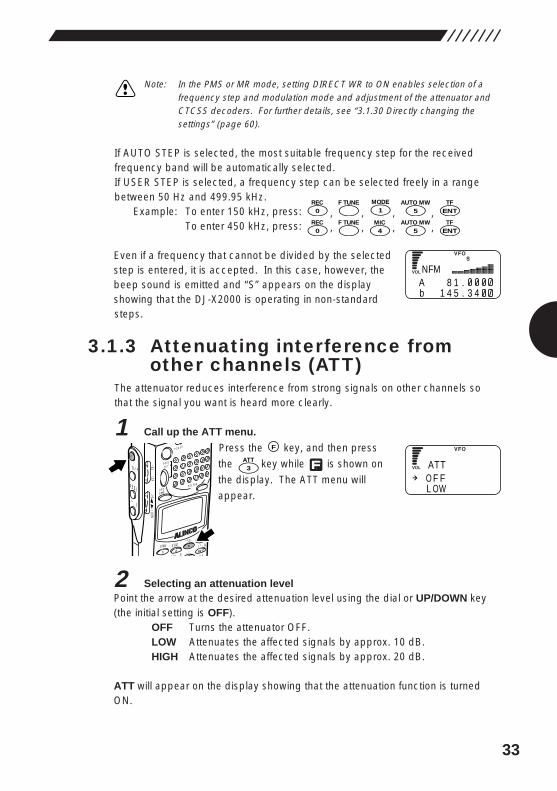
Even if a frequency that cannot be divided by the selectedstep is entered, it is accepted. In this case, however, thebeep sound is emitted and “S” appears on the displayshowing that the DJ-X2000 is operating in non-standardsteps.
3.1.3 Attenuating interference fromother channels (ATT)
The attenuator reduces interference from strong signals on other channels sothat the signal you want is heard more clearly.
1 Call up the ATT menu.
Press the key, and then press
the key while is shown on
the display. The ATT menu will
appear.
2 Selecting an attenuation levelPoint the arrow at the desired attenuation level using the dial or UP/DOWN key(the initial setting is OFF).
OFF Turns the attenuator OFF.LOW Attenuates the affected signals by approx. 10 dB.HIGH Attenuates the affected signals by approx. 20 dB.
ATT will appear on the display showing that the attenuation function is turnedON.
3ATT
F
MODE
AUTO MW
MIC A-B S
M NAMESTEP
ATTSET
POWER
PMS
VFOMR MW
A B
SET
KL
�3
6
21 RF C
HELP
MONI
F
SRCH
LAMP
SQL VOL
DOWN UP
ENTTF
5AUTO MW
4MICF TUNE
0REC
ENTTF
5AUTO MW
1MODEF TUNE
0REC
NA 8 1 .b 1 4 5 . 3 4
FM
O F FL OW
ATT
34
Note: • The attenuation level slightly varies depending on the frequency.• In the PMS or MR mode, setting DIRECT WR to ON enables selection of a
frequency step and modulation mode and adjustment of the attenuator andCTCSS decoders. For further details, see “3.1.30 Directly changing thesettings” (page 60).
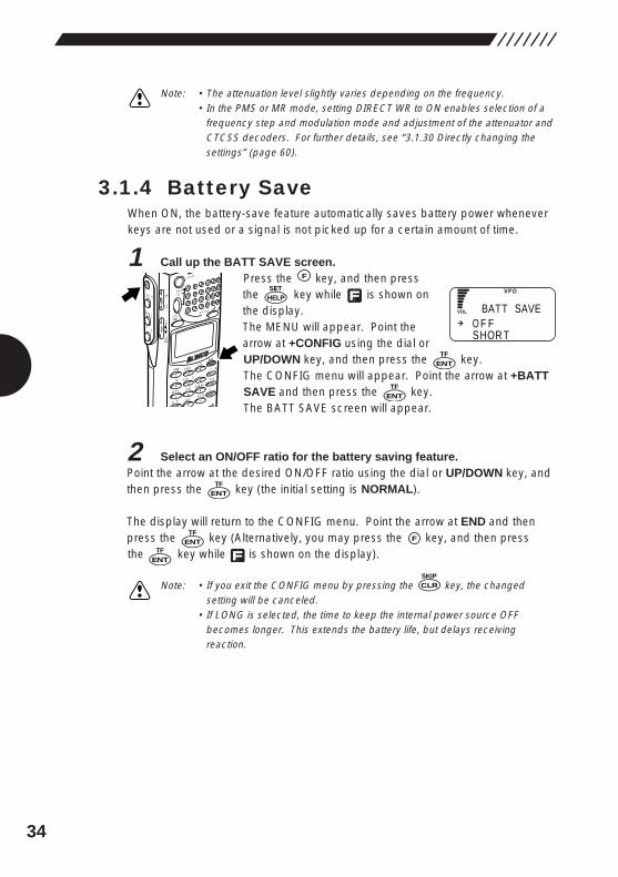
3.1.4 Battery SaveWhen ON, the battery-save feature automatically saves battery power wheneverkeys are not used or a signal is not picked up for a certain amount of time.
1 Call up the BATT SAVE screen.Press the key, and then pressthe key while is shown onthe display.The MENU will appear. Point thearrow at +CONFIG using the dial orUP/DOWN key, and then press the key.The CONFIG menu will appear. Point the arrow at +BATTSAVE and then press the key.The BATT SAVE screen will appear.
2 Select an ON/OFF ratio for the battery saving feature.Point the arrow at the desired ON/OFF ratio using the dial or UP/DOWN key, andthen press the key (the initial setting is NORMAL).
The display will return to the CONFIG menu. Point the arrow at END and thenpress the key (Alternatively, you may press the key, and then press the key while is shown on the display).
Note: • If you exit the CONFIG menu by pressing the key, the changedsetting will be canceled.
• If LONG is selected, the time to keep the internal power source OFFbecomes longer. This extends the battery life, but delays receivingreaction.
CLRSKIP
FENTTF
ENTTF
ENTTF
ENTTF
HELPSET
F
MODE
AUTO MW
MIC
SCRTPRIO
REC
CTCSS
F TUNE
A-B S
M NAME
TF
SKIP
STEPATT
SET
POWER
PMS
VFOMR MW
A B
SET
KL
�3
6
98
0
5
21
4
CLR
ENT
SCN
RF C
HELP
7
MONI
F
SRCH
LAMP
SQL VOL
DOWN UP O F F
SHOR T
BATT SAVE
ENTTF
35
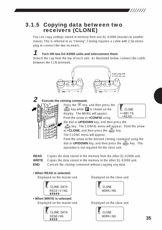
3.1.5 Copying data between tworeceivers (CLONE)
You can copy settings stored in memory from one DJ-X2000 (master) to another(slave). This is referred to as "cloning". Cloning requires a cable with 2.5ø stereoplug to connect the two receivers.
1 Turn ON two DJ-X2000 units and interconnect them.Detach the cap from the top of each unit. As illustrated below, connect the cablebetween the CLN terminals.
2 Execute the cloning command.Press the key, and then press the
key while is shown on thedisplay. The MENU will appear.Point the arrow at +CONFIG usingthe dial or UP/DOWN key, and then press the
key. The CONFIG menu will appear. Point the arrowat +CLONE, and then press the key.The CLONE menu will appear.Point the arrow at the desired cloning command using thedial or UP/DOWN key, and then press the key. Thisoperation is not required for the slave unit.
READ Copies the data stored in the memory from the other DJ-X2000 unit.WRITE Copies the data stored in the memory to the other DJ-X2000 unit.END Cancels the cloning command without copying any data.
• When READ is selected:Displayed on the master unit Displayed on the slave unit
• When WRITE is selected:Displayed on the master unit Displayed on the slave unit
WORK I NGCLONE
S END I NGCLONE DATA
WORK I NGCLONE
R ECE I V I NGCLONE DATA
ENTTF
ENTTF
HELPSET
F
MODE
AUTO MW
MIC
SCRTPRIO
REC
CTCSS
F TUNE
A-B S
M NAME
TF
SKIP
STEPATT
SET
POWER
PMS
VFOMR MW
A B
SET
KL
�3
6
98
0
5
21
4
CLR
ENT
SCN
RF C
HELP
7
MONI
F
SRCH
LAMP
SQL VOL
DOWN UP
ENTTF
Audio plug with2.5 mm dia. pin
WR I T ERE AD
CLONE++
36
When the cloning procedure is finished, the slave unit returns to the normalscreen and the master unit to the CLONE menu.
3 Finish the cloning procedure.Once the cloning procedure is finished, disconnect the cable from both DJ-X2000 units. Press the key on the master unit to exit the CLONE menu. The slave unit can be used without this operation.
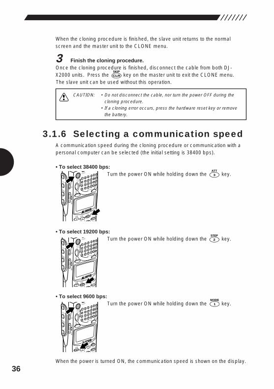
3.1.6 Selecting a communication speedA communication speed during the cloning procedure or communication with apersonal computer can be selected (the initial setting is 38400 bps).
• To select 38400 bps:Turn the power ON while holding down the key.
• To select 19200 bps:Turn the power ON while holding down the key.
• To select 9600 bps:Turn the power ON while holding down the key.
When the power is turned ON, the communication speed is shown on the display.
1MODE
MODE
AUTO MW
MIC A-B S
M NAMESTEP
ATTSET
POWER
PMS
VFOMR MW
A B
SET
KL
�3
6
21 RF C
HELP
MONI
F
SRCH
LAMP
SQL VOL
DOWN U P
2STEP
MODE
AUTO MW
MIC A-B S
M NAMESTEP
ATTSET
POWER
PMS
VFOMR MW
A B
SET
KL
�3
6
21 RF C
HELP
MONI
F
SRCH
LAMP
SQL VOL
DOWN U P
3ATT
MODE
AUTO MW
MIC A-B S
M NAMESTEP
ATTSET
POWER
PMS
VFOMR MW
A B
SET
KL
�3
6
21 RF C
HELP
MONI
F
SRCH
LAMP
SQL VOL
DOWN U P
CLRSKIP
CAUTION: • Do not disconnect the cable, nor turn the power OFF during thecloning procedure.
• If a cloning error occurs, press the hardware reset key or removethe battery.
37
Note: • The cloning procedure or communication with a personal computer is notpossible between DJ-X2000 units with different communication speeds.
• The initial value is a high speed of 38400 bps. If there are too manycommunication errors at this speed, retry the communication at a lowerspeed, e.g., 9600 bps.
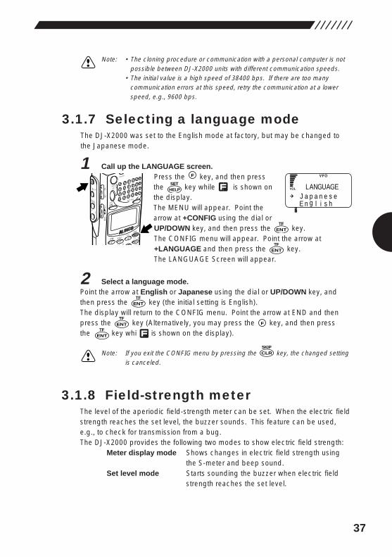
3.1.7 Selecting a language modeThe DJ-X2000 was set to the English mode at factory, but may be changed tothe Japanese mode.
1 Call up the LANGUAGE screen.Press the key, and then pressthe key while is shown onthe display.The MENU will appear. Point thearrow at +CONFIG using the dial orUP/DOWN key, and then press the key.The CONFIG menu will appear. Point the arrow at+LANGUAGE and then press the key.The LANGUAGE Screen will appear.
2 Select a language mode.Point the arrow at English or Japanese using the dial or UP/DOWN key, andthen press the key (the initial setting is English).The display will return to the CONFIG menu. Point the arrow at END and thenpress the key (Alternatively, you may press the key, and then press the key whi is shown on the display).
Note: If you exit the CONFIG menu by pressing the key, the changed settingis canceled.
3.1.8 Field-strength meterThe level of the aperiodic field-strength meter can be set. When the electric fieldstrength reaches the set level, the buzzer sounds. This feature can be used,e.g., to check for transmission from a bug.The DJ-X2000 provides the following two modes to show electric field strength:
Meter display mode Shows changes in electric field strength usingthe S-meter and beep sound.
Set level mode Starts sounding the buzzer when electric fieldstrength reaches the set level.
CLRSKIP
FENTTF
ENTTF
ENTTF
ENTTF
HELPSET
F
MODE
AUTO MW
MIC A-B S
M NAMESTEP
ATTSET
POWER
PMS
VFOMR MW
A B
SET
KL
�3
6
21 RF C
HELP
MONI
F
SRCH
LAMP
SQL VOL
DOWN U P
ENTTF
E n g l i s hJ a p a n e s e
LANGUAGE
�
38
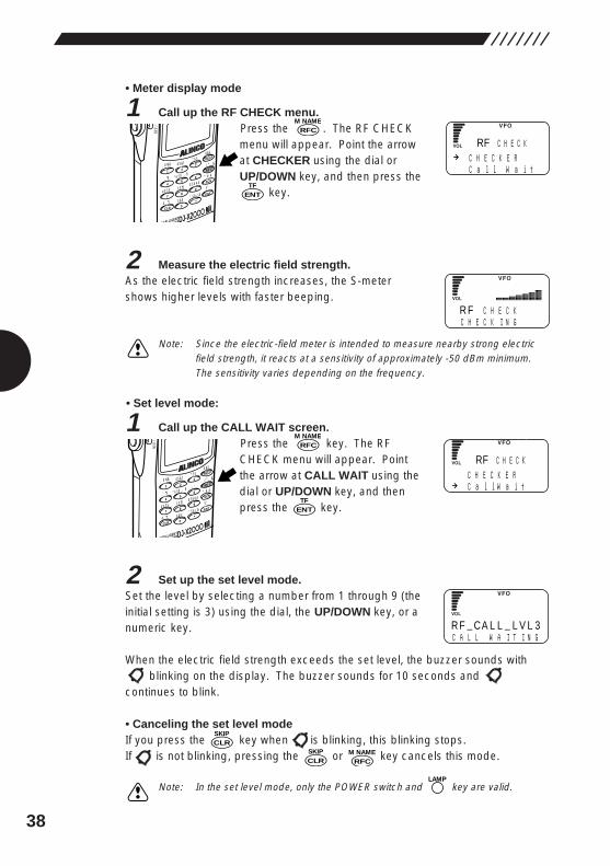
• Meter display mode
1 Call up the RF CHECK menu.Press the . The RF CHECKmenu will appear. Point the arrowat CHECKER using the dial orUP/DOWN key, and then press the
key.
2 Measure the electric field strength.As the electric field strength increases, the S-metershows higher levels with faster beeping.
Note: Since the electric-field meter is intended to measure nearby strong electricfield strength, it reacts at a sensitivity of approximately -50 dBm minimum.The sensitivity varies depending on the frequency.
• Set level mode:
1 Call up the CALL WAIT screen.Press the key. The RFCHECK menu will appear. Pointthe arrow at CALL WAIT using thedial or UP/DOWN key, and thenpress the key.
2 Set up the set level mode.Set the level by selecting a number from 1 through 9 (theinitial setting is 3) using the dial, the UP/DOWN key, or anumeric key.
When the electric field strength exceeds the set level, the buzzer sounds withblinking on the display. The buzzer sounds for 10 seconds and
continues to blink.
• Canceling the set level modeIf you press the key when is blinking, this blinking stops.If is not blinking, pressing the or key cancels this mode.
Note: In the set level mode, only the POWER switch and key are valid.LAMP
RFCM NAME
CLRSKIP
ENTTF
RFCM NAME
MODE
AUTO MW
INTELLIGENTCEIVERDJ-X2
MIC
SCRTPRIO
REC
CTCSS
F TUNE
A-B S
M NAME
TF
SKIP
STEPATT
SET
KL
�3
6
98
0
5
21
4
CLR
ENT
MIC
SCN
RF C
HELP
7
P
DOWN
ENTTF
RFCM NAME
MODE
AUTO MW
INTELLIGENTCEIVERDJ-X2
MIC
SCRTPRIO
REC
CTCSS
F TUNE
A-B S
M NAME
TF
SKIP
STEPATT
SET
KL
�3
6
98
0
5
21
4
CLR
ENT
MIC
SCN
RF C
HELP
7
P
DOWN
CLRSKIP
R FI N
C H E C KC H E C K G
C H E C K E RC a l l W a i t
RF KC H E C
R F CA L L L V L 3C A L L W A I T I N G
C H E C K E RC a l l W a i t
RF C H E C K
39
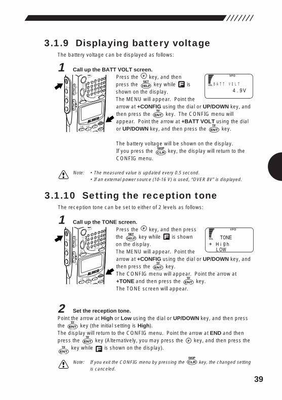
3.1.9 Displaying battery voltageThe battery voltage can be displayed as follows:
1 Call up the BATT VOLT screen.Press the key, and thenpress the key while isshown on the display.The MENU will appear. Point thearrow at +CONFIG using the dial or UP/DOWN key, andthen press the key. The CONFIG menu willappear. Point the arrow at +BATT VOLT using the dialor UP/DOWN key, and then press the key.
The battery voltage will be shown on the display.If you press the key, the display will return to theCONFIG menu.
Note: • The measured value is updated every 0.5 second.• If an external power source (10-16 V) is used, “OVER 8V” is displayed.
3.1.10 Setting the reception toneThe reception tone can be set to either of 2 levels as follows:
1 Call up the TONE screen.Press the key, and then pressthe key while is shownon the display.The MENU will appear. Point thearrow at +CONFIG using the dial or UP/DOWN key, andthen press the key.The CONFIG menu will appear. Point the arrow at+TONE and then press the key.The TONE screen will appear.
2 Set the reception tone.Point the arrow at High or Low using the dial or UP/DOWN key, and then pressthe key (the initial setting is High).The display will return to the CONFIG menu. Point the arrow at END and thenpress the key (Alternatively, you may press the key, and then press the
key while is shown on the display).
Note: If you exit the CONFIG menu by pressing the key, the changed settingis canceled.
CLRSKIP
ENTTF
FENTTF
ENTTF
ENTTF
ENTTF
HELPSET
F
MODE
AUTO MW
MIC A-B S
M NAMESTEP
ATTSET
POWER
PMS
VFOMR MW
A B
SET
KL
�3
6
21 RF C
HELP
MONI
F
SRCH
LAMP
SQL VOL
DOWN UP
CLRSKIP
ENTTF
ENTTF
HELPSET
F
MODE
AUTO MW
MIC A-B S
M NAMESTEP
ATTSET
POWER
PMS
VFOMR MW
A B
SET
KL
�3
6
21 RF C
HELP
MONI
F
SRCH
LAMP
SQL VOL
DOWN UP
B4 . 9 V
A T T V O L T
H i g hL OW
TONE

40
3.1.11 Selecting the BELL modeIn this mode, when the squelch is canceled, a buzzer sounds.
1 Call up the BELL screen.Press the key, and thenpress the key while isshown on the display.The MENU will appear. Point thearrow at +CONFIG using the dial or UP/DOWN key, andthen press the key.The CONFIG menu will appear. Point the arrow at+BELL and then press the key.The BELL screen will appear.
2 Turn the BELL mode ON/OFF.Point the arrow at ON or OFF using the dial or UP/DOWN key, and then pressthe key (the initial setting is OFF).When squelch is canceled, the buzzer sounds for 10 seconds and startsblinking. Pressing the key cancels this blinking.
The display will return to the CONFIG menu. Point the arrow at END and thenpress the key (Alternatively, you may press the key, and then press
the key while is shown on the display).
Note: If you exit the CONFIG menu by pressing the key, the changed settingis cancelled.
3.1.12 Changing the initial messageThe initial message that appears after the power has been turned ON can bechanged as follows:
1 Call up the MESSAGE screen.Press the key, and then pressthe key while is shownon the display.The MENU will appear. Point the arrow at +CONFIGusing the dial or UP/DOWN key and then press thekey.The CONFIG menu will appear. Point the arrow at+MESSAGE and then press the key.The MESSAGE screen will appear.
ENTTF
HELPSET
MODE
AUTO MW
MIC A-B S
M NAMESTEP
ATTSET
POWER
PMS
VFOMR MW
A B
SET
KL
�3
6
21 RF C
HELP
MONI
F
SRCH
LAMP
SQL VOL
DOWN UP
CLRSKIP
ENTTF
FENTTF
CLRSKIP
ENTTF
ENTTF
ENTTF
HELPSET
F
MODE
AUTO MW
MIC A-B S
M NAMESTEP
ATTSET
POWER
PMS
VFOMR MW
A B
SET
KL
�3
6
21 RF C
HELP
MONI
F
SRCH
LAMP
SQL VOL
DOWN UP
OF FON
BEL L
1A BCDE FGH I J K
A L I NCO
L I NE MSG
ENTTF
F
41
2 Enter a message.Select each character by turning the dial, and then establish it by pressing theDOWN key. Pressing the UP key allows you to cancel the established character.Up to 36 characters may be entered (the initial setting is ALINCO INTELLIGENTRECEIVER).
3 Finish the setting.After you have finished entering the characters, press the key.
The display will return to the CONFIG menu. Point the arrow at END and thenpress the key (Alternatively, you may press the key, and then press the
key while is shown on the display.
Note: • If you exit the CONFIG menu by pressing the key, the changedsetting is canceled.
• If you turn the dial while holding down the key, you can move 11characters ahead.
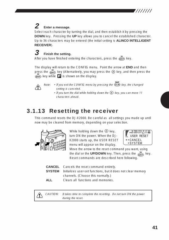
3.1.13 Resetting the receiverThis command resets the DJ-X2000. Be careful as all settings you made up untilnow may be cleared from memory, depending on your selection.
While holding down the key,turn ON the power. When the DJ-X2000 starts up, the USER RESETmenu will appear on the display.Move the arrow to the reset command you want, usingthe dial or the UP/DOWN key. Then, press the key.Reset commands are described here following.
CANCEL Cancels the reset command entirely.SYSTEM Initializes user-set functions, but it does not clear memory
channels. (Choose this normally.)ALL Clears all functions and memories.
ENTTF
F
POWER
RX/ST
PMS
MR MW
SETMONI
F
SR
SQL VOL
CLNS P
F
CLRSKIP
ENTTF
F
ENTTF
ENTTF
CANCE LS Y S T EM
USER RESET
CAUTION: It takes time to complete the resetting. Do not turn ON the powerduring the reset.
42
3.1.14 Tuning in frequencies in thePMS/MR modes (M.TUNE)
You can tune in frequencies in the PMS and MR modes. You do not have toreturn to the VFO mode.
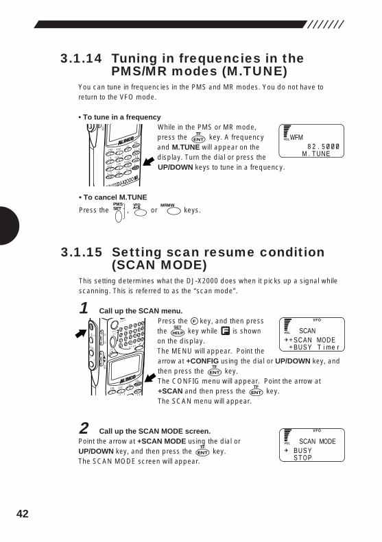
• To tune in a frequency While in the PMS or MR mode,press the key. A frequencyand M.TUNE will appear on thedisplay. Turn the dial or press theUP/DOWN keys to tune in a frequency.
• To cancel M.TUNE
Press the , or keys.
3.1.15 Setting scan resume condition(SCAN MODE)
This setting determines what the DJ-X2000 does when it picks up a signal whilescanning. This is referred to as the “scan mode”.
1 Call up the SCAN menu.Press the key, and then pressthe key while is shownon the display.The MENU will appear. Point thearrow at +CONFIG using the dial or UP/DOWN key, andthen press the key.The CONFIG menu will appear. Point the arrow at+SCAN and then press the key.The SCAN menu will appear.
2 Call up the SCAN MODE screen.Point the arrow at +SCAN MODE using the dial orUP/DOWN key, and then press the key.The SCAN MODE screen will appear.
ENTTF
ENTTF
ENTTF
HELPSET
MODE
AUTO MW
MIC A-B S
M NAMESTEP
ATTSET
POWER
PMS
VFOMR MW
A B
SET
KL
�3
6
21 RF C
HELP
MONI
F
SRCH
LAMP
SQL VOL
DOWN UP
MRMWA=BVFOPMS
SET
ENTTF
MODE
AUTO MW
INTELLIGENTCEIVERDJ-X2
MIC
SCRTPRIO
REC
CTCSS
F TUNE
A-B S
M NAME
TF
SKIP
STEPATT
SET
KL
�3
6
98
0
5
21
4
CLR
ENT
MIC
SCN
RF C
HELP
7
P
DOWN
W8 2 . 5
M . T UNE
FM
SCAN MODEBUS Y T i me r
SCAN
BUS YS T O P
SCAN MODE
F
43
3 Select a scanning option.Point the arrow at the desired option using the dial or UP/DOWN key, and thenpress the key. The available scanning options are described below (theinitial setting is BUSY):
BUSY Busy scan. The DJ-X2000 stays on any signal it locates untilthe signal vanishes. Once the signal disappears, scanning isresumed.
STOP The DJ-X2000 stops scanning on the first signal it locates.Scanning is not resumed after the signal vanishes.
TIMER When the currently transmitted signals of any frequency arereceived, scanning is paused for a given period of time. Afterthis specific time period, scanning is resumed even if thesignals are being received. For setting the pause period, see“3.1.17 Setting the scanning pause period” (page 44).
The display will return to the SCAN menu. Point the arrow at END using the dialor UP/DOWN key, and then press the key (Alternatively, you may press the
key, and then press the key while is shown on the display).
Note: If you exit the SCAN menu by pressing the menu, the changed settingis canceled.
3.1.16 Setting scan signal levelThis setting specifies the minimum signal level used in scanning. Scanning willstop only when the DJ-X2000 locates a signal of this strength or stronger.
1 Call up the SCAN menu.Press the key, and then pressthe key while is shownon the display.The MENU will appear. Point thearrow at +CONFIG using the dial or UP/DOWN key, andthen press the key.The CONFIG menu will appear. Point the arrow at+SCAN and then press the key.The SCAN menu will appear.
2 Call up the S_LEVEL screen. Point the arrow to +S_LEVEL using the dial or theUP/DOWN key, and then press the key.The S_LEVEL screen will appear.
ENTTF
ENTTF
ENTTF
HELPSET
MODE
AUTO MW
MIC A-B S
M NAMESTEP
ATTSET
POWER
PMS
VFOMR MW
A B
SET
KL
�3
6
21 RF C
HELP
MONI
F
SRCH
LAMP
SQL VOL
DOWN UP
CLRSKIP
ENTTF
ENTTF
ENTTF
SCAN MODEBUS Y T i me r
SCAN
SO F FON 1
LEVEL
F
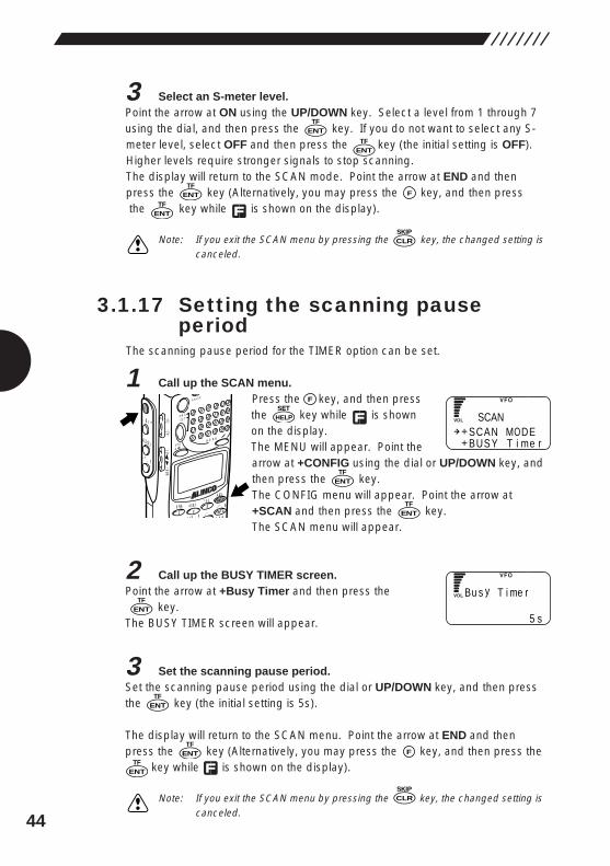
44
3 Select an S-meter level.Point the arrow at ON using the UP/DOWN key. Select a level from 1 through 7using the dial, and then press the key. If you do not want to select any S-meter level, select OFF and then press the key (the initial setting is OFF).Higher levels require stronger signals to stop scanning.The display will return to the SCAN mode. Point the arrow at END and thenpress the key (Alternatively, you may press the key, and then pressthe key while is shown on the display).
Note: If you exit the SCAN menu by pressing the key, the changed setting iscanceled.
3.1.17 Setting the scanning pauseperiod
The scanning pause period for the TIMER option can be set.
1 Call up the SCAN menu.Press the key, and then pressthe key while is shownon the display.The MENU will appear. Point thearrow at +CONFIG using the dial or UP/DOWN key, andthen press the key.The CONFIG menu will appear. Point the arrow at+SCAN and then press the key.The SCAN menu will appear.
2 Call up the BUSY TIMER screen.Point the arrow at +Busy Timer and then press the
key.The BUSY TIMER screen will appear.
3 Set the scanning pause period.Set the scanning pause period using the dial or UP/DOWN key, and then pressthe key (the initial setting is 5s).
The display will return to the SCAN menu. Point the arrow at END and thenpress the key (Alternatively, you may press the key, and then press the
key while is shown on the display).
Note: If you exit the SCAN menu by pressing the key, the changed setting iscanceled.
CLRSKIP
FENTTF
ENTTF
ENTTF
ENTTF
ENTTF
HELPSET
MODE
AUTO MW
MIC A-B S
M NAMESTEP
ATTSET
POWER
PMS
VFOMR MW
A B
SET
KL
�3
6
21 RF C
HELP
MONI
F
SRCH
LAMP
SQL VOL
DOWN UP
CLRSKIP
FENTTF
ENTTF
ENTTF
ENTTF
SCAN MODEBUS Y T i me r
SCAN
B
5 s
u s y T i me r
ENTTF
F

45
3.1.18 Turning the priority functionON/OFF
The priority function checks another channel (priority channel) every 5 secondswhile monitoring the current frequency. For the settings of the priority feature,see “3.1.19 Selecting a priority option” (page 45), “3.1.20 Selecting a prioritychannel” (page 46), and “3.1.21 Specifying a priority interval” (page 47).
• To turn the priority function ONPress the key ,and then pressthe key while is shownon the display. PRIO will appearat the top of the display. Thismeans the priority function is ON.
• Turn the priority feature OFF.Press the key, and then press the key with shown on the display.“PRI” shown at the top of the screen will disappear showing that the priorityfeature is turned OFF.
Note: If the priority feature is ON, the CH SCOPE mode is disabled.
3.1.19 Selecting a priority optionSelect an operation option of the DJ-X2000, which is applicable if signals arereceived on the priority channel when the priority feature is active.
1 Call up the PRIO menu.Press the key, and thenpress the key while isshown on the display.The MENU will appear. Point thearrow at +PRIO using the dial or UP/DOWN key, andthen press the key.The PRIO menu will appear.
ENTTF
F
MODE
AUTO MW
MIC A-B S
M NAMESTEP
ATTSET
POWER
PMS
VFOMR MW
A B
SET
KL
�3
6
21 RF C
HELP
MONI
F
SRCH
LAMP
SQL VOL
DOWN UP
8PRIO
F
8PRIO
F
MODE
AUTO MW
MIC
SCRTPRIO
REC
CTCSS
F TUNE
A-B S
M NAME
TF
SKIP
STEPATT
SET
POWER
PMS
VFOMR MW
A B
SET
KL
�3
6
98
5
21
4
ENT
SCN
RF C
HELP
7
MONI
F
SRCH
LAMP
SQL VOL
DOWN UP
NA 1 4 5 . 3 4b 8 .
FM
PR I F REQPR I MODE
PR I OHELPSET
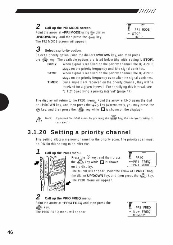
46
2 Call up the PRI MODE screen.Point the arrow at +PRI MODE using the dial orUP/DOWN key, and then press the key.The PRI MODE screen will appear.
3 Select a priority option.Select a priority option using the dial or UP/DOWN key, and then press the key. The available options are listed below (the initial setting is STOP).
BUSY When signal is received on the priority channel, the DJ-X2000stays on the priority frequency until ithe signal vanishes.
STOP When signal is received on the priority channel, the DJ-X2000stays on the priority frequency even after the signal vanishes.
TIMER Once signals are received on the priority channel, they will bereceived for a given interval. For specifying this interval, see“3.1.21 Specifying a priority interval” (page 47).
The display will return to the PRIO menu. Point the arrow at END using the dialor UP/DOWN key, and then press the key (Alternatively, you may press the
key, and then press the key while is shown on the display).
Note: If you exit the PRIO menu by pressing the key, the changed setting iscanceled.
3.1.20 Setting a priority channelThis setting allots a memory channel for the priority scan. The priority scan mustbe ON for this setting to be effective.
1 Call up the PRIO menu.Press the key, and then pressthe key while is shownon the display.The MENU will appear. Point the arrow at +PRIO usingthe dial or UP/DOWN key, and then press the key.The PRIO menu will appear.
2 Call up the PRIO FREQ menu.Point the arrow at +PRIO FREQ and then press the
key.The PRIO FREQ menu will appear.
ENTTF
ENTTF
HELPSET
F
MODE
AUTO MW
MIC A-B S
M NAMESTEP
ATTSET
POWER
PMS
VFOMR MW
A B
SET
KL
�3
6
21 RF C
HELP
MONI
F
SRCH
LAMP
SQL VOL
DOWN UP
CLRSKIP
F
ENTTF
ENTTF
ENTTF
ENTTF
PR I F REQPR I MODE
PR I O
N o w F REQMEMORY
PR I FREQ
S T O PT I MER
PR I MODE
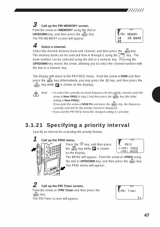
47
3 Call up the PRI MEMORY screen.Point the arrow at +MEMORY using the dial orUP/DOWN key, and then press the key.The PRI MEMORY screen will appear.
4 Select a channel.Select the desired memory bank and channel, and then press the key.The memory bank can be selected from A through E using the key. Thebank number can be selected using the dial or a numeric key. Pressing theUP/DOWN key moves the arrow, allowing you to select the channel number withthe dial or a numeric key.
The display will return to the PRI FREQ menu. Point the arrow at END and thenpress the key (Alternatively, you may press the key, and then press the
key while is shown on the display).
Note: • To select the currently received frequency for the priority channel, point thearrow at Now FREQ in step 2 and then press the key (the initialsetting is Now FREQ).If you point the arrow at NOW Pri and press the key, the frequencycurrently selected for the priority channel is displayed.
• If you exit the PRI FREQ menu the changed setting is canceled.
3.1.21 Specifying a priority intervalSpecify an interval for activating the priority feature.
1 Call up the PRIO menu.Press the key, and then pressthe key while is shownon the display.The MENU will appear. Point the arrow at +PRIO usingthe dial or UP/DOWN key, and then press the key.The PRIO memu will appear.
2 Call up the PRI Timer screen.Point the arrow at +PRI Timer and then press the
key.The PRI Timer screen will appear.
ENTTF
ENTTF
HELPSET
F
MODE
AUTO MW
MIC A-B S
M NAMESTEP
ATTSET
POWER
PMS
VFOMR MW
A B
SET
KL
�3
6
21 RF C
HELP
MONI
F
SRCH
LAMP
SQL VOL
DOWN UP
ENTTF
ENTTF
FENTTF
ENTTF
ENTTF
PR I F REQPR I MODE
PR I O
P
5 s
R I T i me r
PA 8 .
R I MEMORY
ENTTF
F TUNE
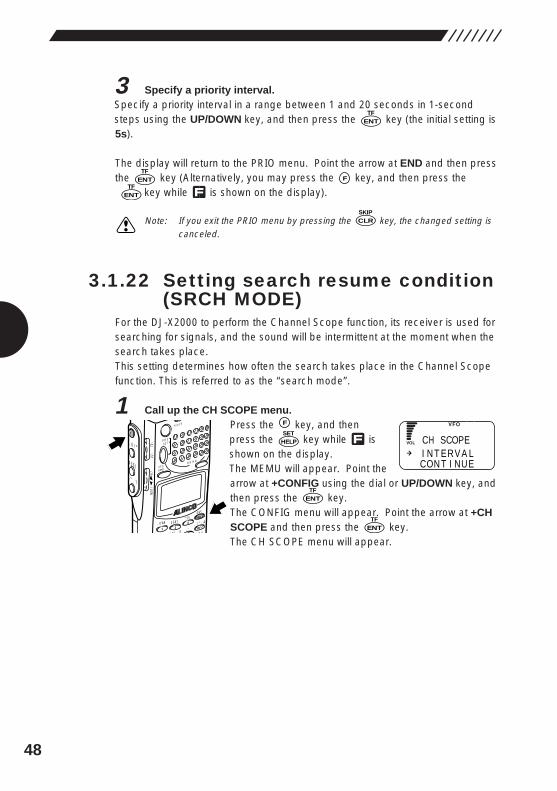
48
3 Specify a priority interval.Specify a priority interval in a range between 1 and 20 seconds in 1-secondsteps using the UP/DOWN key, and then press the key (the initial setting is5s).
The display will return to the PRIO menu. Point the arrow at END and then pressthe key (Alternatively, you may press the key, and then press the
key while is shown on the display).
Note: If you exit the PRIO menu by pressing the key, the changed setting iscanceled.
3.1.22 Setting search resume condition(SRCH MODE)
For the DJ-X2000 to perform the Channel Scope function, its receiver is used forsearching for signals, and the sound will be intermittent at the moment when thesearch takes place.This setting determines how often the search takes place in the Channel Scopefunction. This is referred to as the “search mode”.
1 Call up the CH SCOPE menu.Press the key, and thenpress the key while isshown on the display.The MEMU will appear. Point thearrow at +CONFIG using the dial or UP/DOWN key, andthen press the key.The CONFIG menu will appear. Point the arrow at +CHSCOPE and then press the key.The CH SCOPE menu will appear.
ENTTF
ENTTF
HELPSET
F
MODE
AUTO MW
MIC A-B S
M NAMESTEP
ATTSET
POWER
PMS
VFOMR MW
A B
SET
KL
�3
6
21 RF C
HELP
MONI
F
SRCH
LAMP
SQL VOL
DOWN UP
CLRSKIP
F
ENTTF
I N T ERV A LCON T I NUE
CH SCOPE
ENTTF
ENTTF
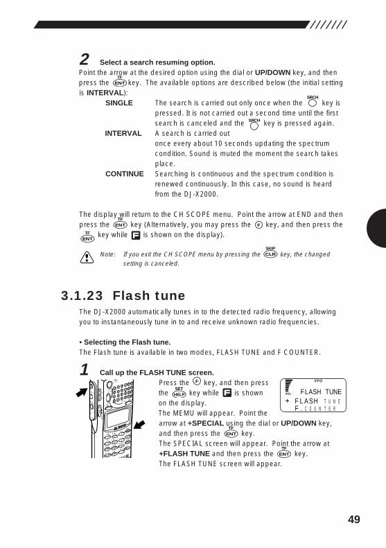
49
2 Select a search resuming option.Point the arrow at the desired option using the dial or UP/DOWN key, and thenpress the key. The available options are described below (the initial settingis INTERVAL):
SINGLE The search is carried out only once when the key ispressed. It is not carried out a second time until the firstsearch is canceled and the key is pressed again.
INTERVAL A search is carried outonce every about 10 seconds updating the spectrumcondition. Sound is muted the moment the search takesplace.
CONTINUE Searching is continuous and the spectrum condition isrenewed continuously. In this case, no sound is heardfrom the DJ-X2000.
The display will return to the CH SCOPE menu. Point the arrow at END and thenpress the key (Alternatively, you may press the key, and then press the
key while is shown on the display).
Note: If you exit the CH SCOPE menu by pressing the key, the changedsetting is canceled.
3.1.23 Flash tuneThe DJ-X2000 automatically tunes in to the detected radio frequency, allowingyou to instantaneously tune in to and receive unknown radio frequencies.
• Selecting the Flash tune.The Flash tune is available in two modes, FLASH TUNE and F COUNTER.
1 Call up the FLASH TUNE screen.Press the key, and then pressthe key while is shownon the display.The MEMU will appear. Point thearrow at +SPECIAL using the dial or UP/DOWN key,and then press the key.The SPECIAL screen will appear. Point the arrow at+FLASH TUNE and then press the key.The FLASH TUNE screen will appear.
ENTTF
ENTTF
HELPSET
F
MODE
AUTO MW
X2
MIC
SCRTPRIO
REC
CTCSS
F TUNE
A-B S
M NAME
TF
SKIP
STEPATT
SET
POWER
PMS
VFOMR MW
A B
SET
KL
�3
6
98
0
5
21
4
CLR
ENT
MIC
SCN
RF C
HELP
7
MONI
F
SRCH
LAMP
SQL VOL
DOWN UP
CLRSKIP
ENTTF
FENTTF
SRCH
SRCH
ENTTF
F L A SH T U N EF . C O U N T E R
FLASH TUNE
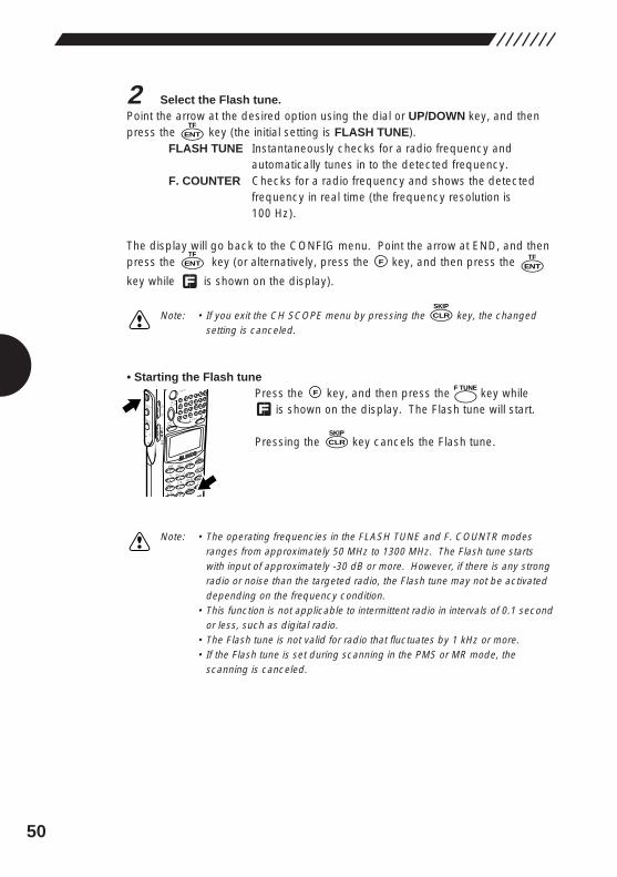
50
2 Select the Flash tune.Point the arrow at the desired option using the dial or UP/DOWN key, and thenpress the key (the initial setting is FLASH TUNE).
FLASH TUNE Instantaneously checks for a radio frequency andautomatically tunes in to the detected frequency.
F. COUNTER Checks for a radio frequency and shows the detectedfrequency in real time (the frequency resolution is100 Hz).
The display will go back to the CONFIG menu. Point the arrow at END, and thenpress the key (or alternatively, press the key, and then press the
key while is shown on the display).
Note: • If you exit the CH SCOPE menu by pressing the key, the changedsetting is canceled.
• Starting the Flash tunePress the key, and then press the key while
is shown on the display. The Flash tune will start.
Pressing the key cancels the Flash tune.
Note: • The operating frequencies in the FLASH TUNE and F. COUNTR modesranges from approximately 50 MHz to 1300 MHz. The Flash tune startswith input of approximately -30 dB or more. However, if there is any strongradio or noise than the targeted radio, the Flash tune may not be activateddepending on the frequency condition.
• This function is not applicable to intermittent radio in intervals of 0.1 secondor less, such as digital radio.
• The Flash tune is not valid for radio that fluctuates by 1 kHz or more.• If the Flash tune is set during scanning in the PMS or MR mode, the
scanning is canceled.
CLRSKIP
F
MODE
AUTO MW
MIC
SCRTPRIO
REC
CTCSS
F TUNE
A-B S
M NAME
TF
SKIP
STEPATT
SET
POWER
PMS
VFOMR MW
A B
SET
KL
�3
6
98
0
5
21
4
CLR
ENT
SCN
RF C
HELP
7
MONI
F
SRCH
LAMP
SQL VOL
DOWN UP
CLRSKIP
ENTTF
FENTTF
ENTTF
F TUNE
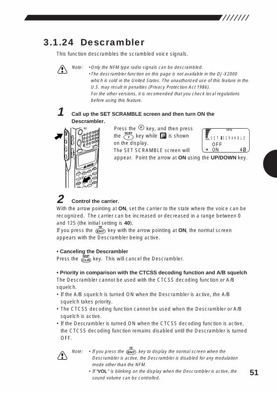
51
3.1.24 DescramblerThis function descrambles the scrambled voice signals.
Note: •Only the NFM type radio signals can be descrambled.•The descrambler function on this page is not available in the DJ-X2000which is sold in the United States. The unauthorized use of this feature in theU.S. may result in penalties (Privacy Protection Act 1986).For the other versions, it is recomended that you check local regulationsbefore using this feature.
1 Call up the SET SCRAMBLE screen and then turn ON theDescrambler.
Press the key, and then pressthe key while is shownon the display.The SET SCRAMBLE screen willappear. Point the arrow at ON using the UP/DOWN key.
2 Control the carrier.With the arrow pointing at ON, set the carrier to the state where the voice can berecognized. The carrier can be increased or decreased in a range between 0and 125 (the initial setting is 40).If you press the key with the arrow pointing at ON, the normal screenappears with the Descrambler being active.
• Canceling the DescramblerPress the key. This will cancel the Descrambler.
• Priority in comparison with the CTCSS decoding function and A/B squelch The Descrambler cannot be used with the CTCSS decoding function or A/Bsquelch.• If the A/B squelch is turned ON when the Descrambler is active, the A/B
squelch takes priority.• The CTCSS decoding function cannot be used when the Descrambler or A/B
squelch is active.• If the Descrambler is turned ON when the CTCSS decoding function is active,
the CTCSS decoding function remains disabled until the Descrambler is turnedOFF.
Note: • If you press the key to display the normal screen when theDescrambler is active, the Descrambler is disabled for any modulationmode other than the NFM.
• If “VOL” is blinking on the display when the Descrambler is active, thesound volume can be controlled.
ENTTF
CLRSKIP
ENTTF
7SCRT
F
MODE
AUTO MW
MIC
SCRTPRIO
REC
CTCSS
F TUNE
A-B S
M NAME
TF
SKIP
STEPATT
SET
POWER
PMS
VFOMR MW
A B
SET
KL
�3
6
98
0
5
21
4
R
ENT
SCN
RF C
HELP
7
MONI
F
SRCH
LAMP
SQL VOL
DOWN UP
SO F FON 4
E T �S C R AMB L E
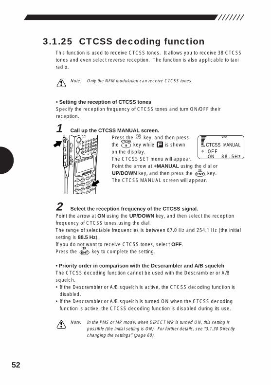
52
3.1.25 CTCSS decoding functionThis function is used to receive CTCSS tones. It allows you to receive 38 CTCSStones and even select reverse reception. The function is also applicable to taxiradio.
Note: Only the NFM modulation can receive CTCSS tones.
• Setting the reception of CTCSS tonesSpecify the reception frequency of CTCSS tones and turn ON/OFF theirreception.
1 Call up the CTCSS MANUAL screen.Press the key, and then pressthe key while is shownon the display.The CTCSS SET menu will appear.Point the arrow at +MANUAL using the dial orUP/DOWN key, and then press the key.The CTCSS MANUAL screen will appear.
2 Select the reception frequency of the CTCSS signal.Point the arrow at ON using the UP/DOWN key, and then select the receptionfrequency of CTCSS tones using the dial.The range of selectable frequencies is between 67.0 Hz and 254.1 Hz (the initialsetting is 88.5 Hz).If you do not want to receive CTCSS tones, select OFF.Press the key to complete the setting.
• Priority order in comparison with the Descrambler and A/B squelchThe CTCSS decoding function cannot be used with the Descrambler or A/Bsquelch.• If the Descrambler or A/B squelch is active, the CTCSS decoding function is
disabled.• If the Descrambler or A/B squelch is turned ON when the CTCSS decoding
function is active, the CTCSS decoding function is disabled during its use.
Note: In the PMS or MR mode, when DIRECT WR is turned ON, this setting ispossible (the initial setting is ON). For further details, see “3.1.30 Directlychanging the settings” (page 60).
ENTTF
ENTTF
9CTCSS
F
MODE
AUTO MW
MIC
SCRTPRIO
REC
CTCSS
F TUNE
A-B S
M NAME
TF
SKIP
STEPATT
SET
POWER
PMS
VFOMR MW
A B
SET
KL
�3
6
98
0
5
21
4
R
ENT
SCN
RF C
HELP
7
MONI
F
SRCH
LAMP
SQL VOL
DOWN UP
CO F FON 8 8 . 5 H z
TCSS MANUAL
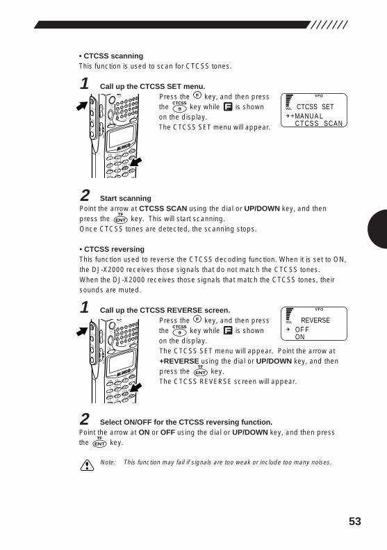
53
• CTCSS scanningThis function is used to scan for CTCSS tones.
1 Call up the CTCSS SET menu.Press the key, and then pressthe key while is shownon the display.The CTCSS SET menu will appear.
2 Start scanningPoint the arrow at CTCSS SCAN using the dial or UP/DOWN key, and thenpress the key. This will start scanning.Once CTCSS tones are detected, the scanning stops.
• CTCSS reversingThis function used to reverse the CTCSS decoding function. When it is set to ON,the DJ-X2000 receives those signals that do not match the CTCSS tones.When the DJ-X2000 receives those signals that match the CTCSS tones, theirsounds are muted.
1 Call up the CTCSS REVERSE screen.Press the key, and then pressthe key while is shownon the display.The CTCSS SET menu will appear. Point the arrow at+REVERSE using the dial or UP/DOWN key, and thenpress the key.The CTCSS REVERSE screen will appear.
2 Select ON/OFF for the CTCSS reversing function.Point the arrow at ON or OFF using the dial or UP/DOWN key, and then pressthe key.
Note: This function may fail if signals are too weak or include too many noises.
ENTTF
ENTTF
9CTCSS
F
MODE
AUTO MW
MIC
SCRTPRIO
REC
CTCSS
F TUNE
A-B S
M NAME
TF
SKIP
STEPATT
SET
POWER
PMS
VFOMR MW
A B
SET
KL
�3
6
98
0
5
21
4
R
ENT
SCN
RF C
HELP
7
MONI
F
SRCH
LAMP
SQL VOL
DOWN UP
ENTTF
9CTCSS
F
MODE
AUTO MW
MIC
SCRTPRIO
REC
CTCSS
F TUNE
A-B S
M NAME
TF
SKIP
STEPATT
SET
POWER
PMS
VFOMR MW
A B
SET
KL
�3
6
98
0
5
21
4
R
ENT
SCN
RF C
HELP
7
MONI
F
SRCH
LAMP
SQL VOL
DOWN UP
MANUA LC T CS S SCAN
CTCSS SET
OF FON
REVERSE
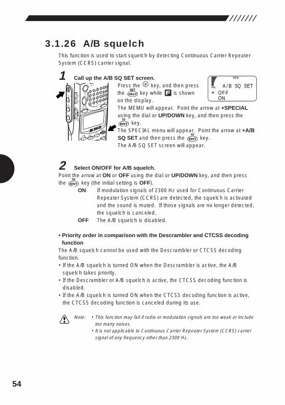
54
3.1.26 A/B squelchThis function is used to start squelch by detecting Continuous Carrier RepeaterSystem (CCRS) carrier signal.
1 Call up the A/B SQ SET screen.Press the key, and then pressthe key while is shownon the display.The MEMU will appear. Point the arrow at +SPECIALusing the dial or UP/DOWN key, and then press the
key.The SPECIAL menu will appear. Point the arrow at +A/BSQ SET and then press the key.The A/B SQ SET screen will appear.
2 Select ON/OFF for A/B squelch.Point the arrow at ON or OFF using the dial or UP/DOWN key, and then pressthe key (the initial setting is OFF).
ON If modulation signals of 2300 Hz used for Continuous CarrierRepeater System (CCRS) are detected, the squelch is activatedand the sound is muted. If those signals are no longer detected,the squelch is canceled.
OFF The A/B squelch is disabled.
• Priority order in comparison with the Descrambler and CTCSS decodingfunction
The A/B squelch cannot be used with the Descrambler or CTCSS decodingfunction.• If the A/B squelch is turned ON when the Descrambler is active, the A/B
squelch takes priority.• If the Descrambler or A/B squelch is active, the CTCSS decoding function is
disabled.• If the A/B squelch is turned ON when the CTCSS decoding function is active,
the CTCSS decoding function is canceled during its use.
Note: • This function may fail if radio or modulation signals are too weak or includetoo many noises.
• It is not applicable to Continuous Carrier Repeater System (CCRS) carriersignal of any frequency other than 2300 Hz.
ENTTF
ENTTF
ENTTF
HELPSET
F
MODE
AUTO MW
MIC A-B S
M NAMESTEP
ATTSET
POWER
PMS
VFOMR MW
A B
SET
KL
�3
6
21 RF C
HELP
MONI
F
SRCH
LAMP
SQL VOL
DOWN UP
OF FON
A / B SQ SET
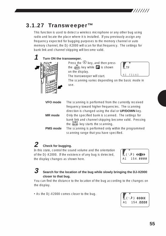
55
3.1.27 Transweeper™This function is used to detect a wireless microphone or any other bug usingradio and locate the place where it is installed. If you previously assign anyfrequency expected for bugging purposes to the memory channel or automemory channel, the DJ-X2000 will scan for that frequency. The settings forbank link and channel skipping will become valid.
1 Turn ON the transweeper.Press the key, and then pressthe key while is shownon the display.The transweeper will start.The scanning varies depending on the basic mode inuse.
VFO mode The scanning is performed from the currently receivedfrequency toward higher frequencies. The scanningdirection is changed using the dial or UP/DOWN key.
MR mode Only the specified bank is scanned. The settings forbank link and channel skipping become valid. Pressingthe key starts the scanning.
PMS mode The scanning is performed only within the programmedscanning range that you have specified.
2 Check for bugging.In this state, control the sound volume and the orientationof the DJ-X2000. If the existence of any bug is detected,the display changes as shown here.
3 Search for the location of the bug while slowly bringing the DJ-X2000closer to that bug.
You can find the distance to the location of the bug according to the changes onthe display.
• As the DJ-X2000 comes closer to the bug.
SCNA~B S
ENTTF
F
MODE
AUTO MW
X2
MIC
SCRTPRIO
REC
CTCSS
F TUNE
A-B S
M NAME
TF
SKIP
STEPATT
SET
POWER
RX/ST
PMS
VFOMR MW
A B
SET
KL
�3
6
98
0
5
21
4
CLR
ENT
MIC
SCN
RF C
HELP
7
MONI
F
SRCH
LAMP
SQL VOL
DOWN UP
T
N NO F O U D
F
A(
1 1 5 4 .)_�, ,
A(
1 1 5 4 .)_�, ,
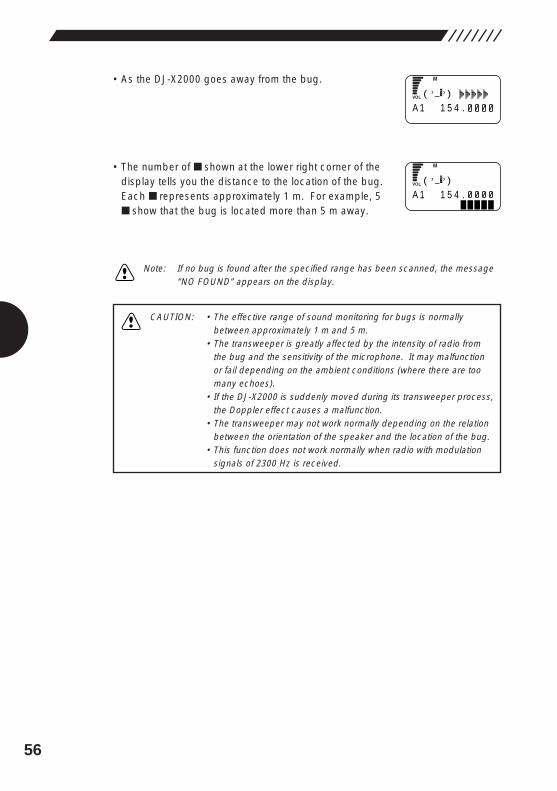
56
CAUTION: • The effective range of sound monitoring for bugs is normallybetween approximately 1 m and 5 m.
• The transweeper is greatly affected by the intensity of radio fromthe bug and the sensitivity of the microphone. It may malfunctionor fail depending on the ambient conditions (where there are toomany echoes).
• If the DJ-X2000 is suddenly moved during its transweeper process,the Doppler effect causes a malfunction.
• The transweeper may not work normally depending on the relationbetween the orientation of the speaker and the location of the bug.
• This function does not work normally when radio with modulationsignals of 2300 Hz is received.
• As the DJ-X2000 goes away from the bug.
• The number of ■ shown at the lower right corner of thedisplay tells you the distance to the location of the bug.Each ■ represents approximately 1 m. For example, 5■ show that the bug is located more than 5 m away.
Note: If no bug is found after the specified range has been scanned, the message“NO FOUND” appears on the display.
A(
1 1 5 4 .)_�, ,
A(
1 1 5 4 .)_�, ,
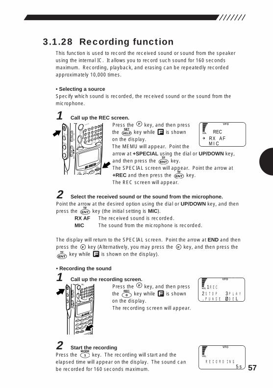
57
3.1.28 Recording functionThis function is used to record the received sound or sound from the speakerusing the internal IC. It allows you to record such sound for 160 secondsmaximum. Recording, playback, and erasing can be repeatedly recordedapproximately 10,000 times.
• Selecting a sourceSpecify which sound is recorded, the received sound or the sound from themicrophone.
1 Call up the REC screen.Press the key, and then pressthe key while is shownon the display.The MEMU will appear. Point thearrow at +SPECIAL using the dial or UP/DOWN key,and then press the key.The SPECIAL screen will appear. Point the arrow at+REC and then press the key.The REC screen will appear.
2 Select the received sound or the sound from the microphone.Point the arrow at the desired option using the dial or UP/DOWN key, and thenpress the key (the initial setting is MIC).
RX AF The received sound is recorded.MIC The sound from the microphone is recorded.
The display will return to the SPECIAL screen. Point the arrow at END and thenpress the key (Alternatively, you may press the key, and then press the
key while is shown on the display).
• Recording the sound
1 Call up the recording screen.Press the key, and then pressthe key while is shownon the display.The recording screen will appear.
2 Start the recordingPress the key. The recording will start and theelapsed time will appear on the display. The sound canbe recorded for 160 seconds maximum.
1MODE
0REC
F
MODE
AUTO MW
J X2
MIC
SCRTPRIO
REC
CTCSS
F TUNE
A-B S
M NAME
TF
SKIP
STEPATT
SET
POWER
PMS
VFOMR MW
A B
SET
KL
�3
6
98
0
5
21
4
CLR
ENT
MIC
SCN
RF C
HELP
7
MONI
F
SRCH
LAMP
SQL VOL
DOWN UP
ENTTF
FF
ENTTF
ENTTF
ENTTF
HELPSET
F
MODE M NAMESTEP
ATTSET
POWER
PMS
VFOMR MW
A B
SET
KL
�3
21 RF C
HELP
MONI
F
SRCH
LAMP
SQL VOL
DOWN UP
RX A FM I C
REC
12 S T O P 3 P L A Y. P U A S E D E L
R E C
R E C O R D I N G5 s
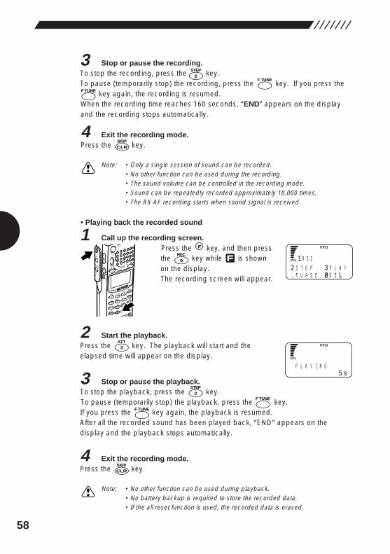
58
3 Stop or pause the recording.To stop the recording, press the key.To pause (temporarily stop) the recording, press the key. If you press the
key again, the recording is resumed.When the recording time reaches 160 seconds, “END” appears on the displayand the recording stops automatically.
4 Exit the recording mode.Press the key.
Note: • Only a single session of sound can be recorded.• No other function can be used during the recording.• The sound volume can be controlled in the recording mode.• Sound can be repeatedly recorded approximately 10,000 times.• The RX AF recording starts when sound signal is received.
• Playing back the recorded sound
1 Call up the recording screen.Press the key, and then pressthe key while is shownon the display.The recording screen will appear.
2 Start the playback.Press the key. The playback will start and theelapsed time will appear on the display.
3 Stop or pause the playback.To stop the playback, press the key.To pause (temporarily stop) the playback, press the key.If you press the key again, the playback is resumed.After all the recorded sound has been played back, “END” appears on thedisplay and the playback stops automatically.
4 Exit the recording mode.Press the key.
Note: • No other function can be used during playback.• No battery backup is required to store the recorded data.• If the all reset function is used, the recorded data is erased.
CLRSKIP
F TUNE
2STEP
3ATT
0REC
F
MODE
AUTO MW
J X2
MIC
SCRTPRIO
REC
CTCSS
F TUNE
A-B S
M NAME
TF
SKIP
STEPATT
SET
POWER
PMS
VFOMR MW
A B
SET
KL
�3
6
98
0
5
21
4
CLR
ENT
MIC
SCN
RF C
HELP
7
MONI
F
SRCH
LAMP
SQL VOL
DOWN UP
CLRSKIP
F TUNE
12 S T O P 3 P L A Y. P U A S E D E L
R E C
P L A Y I N G5 s
F TUNE
F TUNE
2STEP
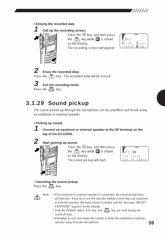
59
• Erasing the recorded data
1 Call up the recording screen.Press the key, and then pressthe key while is shownon the display.The recording screen will appear.
2 Erase the recorded data.Press the key. The recorded data will be erased.
3 Exit the recording mode.Press the key.
3.1.29 Sound pickupThe sound picked up through the microphone can be amplified and heard usingan earphone or external speaker.
• Picking up sound
1 Connect an earphone or external speaker to the SP terminal on thetop of the DJ-X2000.
2 Start picking up sound.Press the key, and then pressthe key while is shownon the display.The sound pickup will start.
• Canceling the sound pickupPress the key.
Note: • If no earphone or external speaker is connected, the sound pickup doesnot function. If you try to use this function without connecting any earphoneor external speaker, the beep sound is emitted and the message “INSERTEARPHONE” appears on the display.
• Only the POWER switch, VOL key, and key are valid during thesound pickup.
• If howling occurs, turn down the volume or keep the earphone or externalspeaker away from the microphone.
CLRSKIP
CLRSKIP
4MIC
F
MODE
AUTO MW
J X2
MIC
SCRTPRIO
REC
CTCSS
F TUNE
A-B S
M NAME
TF
SKIP
STEPATT
SET
POWER
PMS
VFOMR MW
A B
SET
KL
�3
6
98
0
5
21
4
CLR
ENT
MIC
SCN
RF C
HELP
7
MONI
F
SRCH
LAMP
SQL VOL
DOWN UP
CLRSKIP
0REC
0REC
F
MODE
AUTO MW
J X2
MIC
SCRTPRIO
REC
CTCSS
F TUNE
A-B S
M NAME
TF
SKIP
STEPATT
SET
POWER
PMS
VFOMR MW
A B
SET
KL
�3
6
98
0
5
21
4
CLR
ENT
MIC
SCN
RF C
HELP
7
MONI
F
SRCH
LAMPSQL VOL
DOWN UP
12 S T O P 3 P L A Y. P U A S E D E L
R E C
MT h e s o u n dC a n b e h e a r d
I C ON
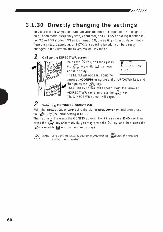
60
3.1.30 Directly changing the settingsThis function allows you to enable/disable the direct changes of the settings formodulation mode, frequency step, attenuator, and CTCSS decoding function inthe MR or PMS modes. When it is turned ON, the settings for modulation mode,frequency step, attenuator, and CTCSS decoding function can be directlychanged in the currently displayed MR or PMS mode.
1 Call up the DIRECT WR screen.Press the key, and then pressthe key while is shownon the display.The MENU will appear. Point thearrow at +CONFIG using the dial or UP/DOWN key, andthen press the key.The CONFIG screen will appear. Point the arrow at+DIRECT WR and then press the key.The DIRECT WR screen will appear.
2 Selecting ON/OFF for DIRECT WR.Point the arrow at ON or OFF using the dial or UP/DOWN key, and then pressthe key (the initial setting is OFF).The display will return to the CONFIG screen. Point the arrow at END and thenpress the key (Alternatively, you may press the key, and then press the
key while is shown on the display).
Note: If you exit the CONFIG screen by pressing the key, the changedsettings are canceled.
CLRSKIP
ENTTF
FENTTF
ENTTF
ENTTF
ENTTF
HELPSET
F
MODE
AUTO MW
MIC
CTCSSA-B S
M NAMESTEP
ATTSET
POWER
PMS
VFOMR MW
A B
SET
KL
�3
65
21
4SCN
RF C
HELP
MONI
F
SRCH
LAMP
SQL VOL
DOWN UP
ONOFF
D I RECT WR
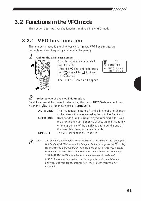
61
3.2 Functions in the VFO modeThis section describes various functions available in the VFO mode.
3.2.1 VFO link functionThis function is used to synchronously change two VFO frequencies, thecurrently received frequency and another frequency.
1 Call up the LINK SET screen.Specify frequencies in bands Aand B of VFO.Press the key, and then pressthe key while is shownon the display.The LINK SET screen will appear.
2 Select a type of the VFO link function.Point the arrow at the desired option using the dial or UP/DOWN key, and thenpress the key (the initial setting is LINK OFF).
AUTO LINK The frequencies in bands A and B interlock and changeat the interval that was set using the auto link function.
USER LINK Both bands A and B are displayed in capital letters andthe VFO link function becomes active. As the frequencyon the upper line of the display is changed, the one onthe lower line changes simultaneously.
LINK OFF The VFO link function is canceled.
Note: The frequency on the upper line may exceed 2149.999950 MHz (the upper
limit for the DJ-X2000) when it is changed. In this case, press the key
toggle between bands A and B. The band shown on the upper line will be
switched to the lower line. The band shown on the lower line (exceeding
2149.9999 MHz) will be included in a range between 0.1 MHz and
2149.999 MHz and then switched to the upper line while maintaining the
difference between the two frequencies. The VFO link function is not
canceled.
A=BVFO
ENTTF
CLRSKIP
F
MODE
AUTO MW
INTELLIGENT
RECEIVERDJ-X2
MIC
SCRTPRIO
REC
CTCSS
F TUNE
A-B S
M NAME
TF
SKIP
STEPATT
SET
POWER
RX/ST
PMS
VFOMR MW
A B
SET
KL
�3
6
98
0
5
21
4
CLR
ENT
MIC
SCN
RF C
HELP
7
MONI
F
SRCH
LAMP
SQL VOL
DOWN UP
AU T O L I NKUS ER L I NK
L I NK SET
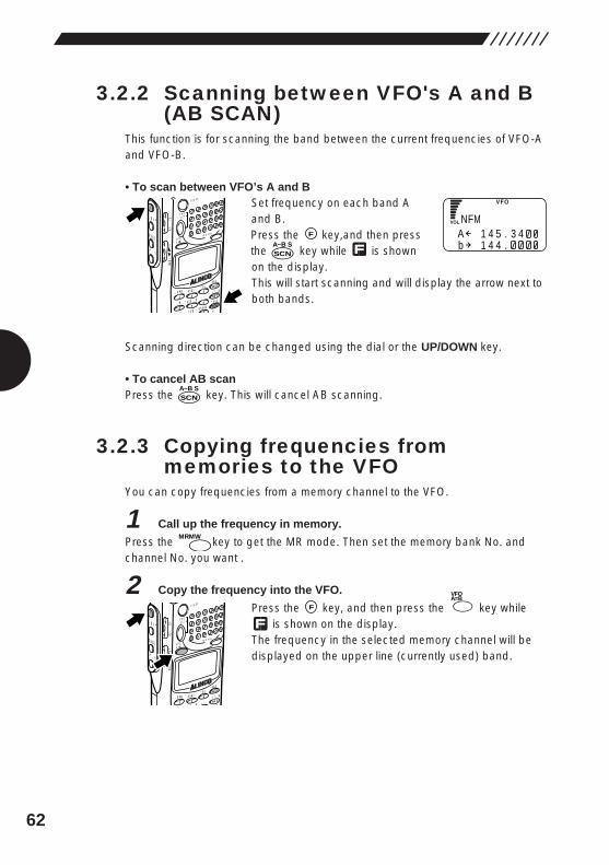
62
3.2.2 Scanning between VFO's A and B (AB SCAN)
This function is for scanning the band between the current frequencies of VFO-Aand VFO-B.
• To scan between VFO’s A and B Set frequency on each band Aand B.Press the key,and then pressthe key while is shownon the display. This will start scanning and will display the arrow next toboth bands.
Scanning direction can be changed using the dial or the UP/DOWN key.
• To cancel AB scanPress the key. This will cancel AB scanning.
3.2.3 Copying frequencies frommemories to the VFO
You can copy frequencies from a memory channel to the VFO.
1 Call up the frequency in memory.
Press the key to get the MR mode. Then set the memory bank No. andchannel No. you want .
2 Copy the frequency into the VFO.
Press the key, and then press the key whileis shown on the display.
The frequency in the selected memory channel will bedisplayed on the upper line (currently used) band.
A=BVFO
F
MODE
AUTO MW
IC A-B S
M NAMESTEP
ATTSET
POWER
PMS
VFOMR MW
A B
SET
KL
�3
21 RF C
HELP
MONI
F
SRCH
LAMP
SQL VOL
DOWN UP
MRMW
SCNA~B S
SCNA~B S
F
MODE
AUTO MW
MIC
SCRTPRIO
CTCSSA-B S
M NAME
TF
STEPATT
SET
POWER
PMS
VFOMR MW
A B
SET
KL
�3
6
9
5
21
4SCN
RF C
HELP
MONI
F
SRCH
LAMP
SQL VOL
DOWN UP
NA 1 4 5 . 3 4b 1 4 4 .
FM
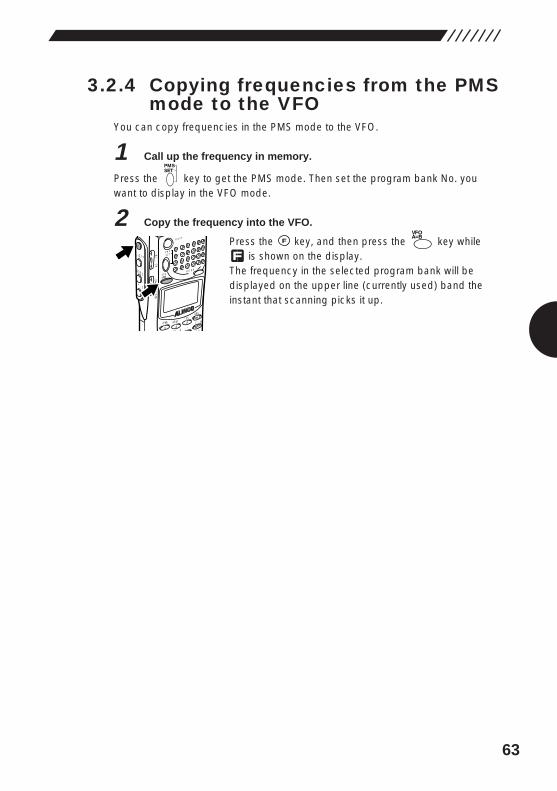
63
3.2.4 Copying frequencies from the PMSmode to the VFO
You can copy frequencies in the PMS mode to the VFO.
1 Call up the frequency in memory.
Press the key to get the PMS mode. Then set the program bank No. youwant to display in the VFO mode.
2 Copy the frequency into the VFO.
Press the key, and then press the key whileis shown on the display.
The frequency in the selected program bank will bedisplayed on the upper line (currently used) band theinstant that scanning picks it up.
A=BVFO
F
MODE
AUTO MW
IC A-B S
M NAMESTEP
ATTSET
POWER
PMS
VFOMR MW
A B
SET
KL
�3
21 RF C
HELP
MONI
F
SRCH
LAMP
SQL VOL
DOWN UP
PMSSET
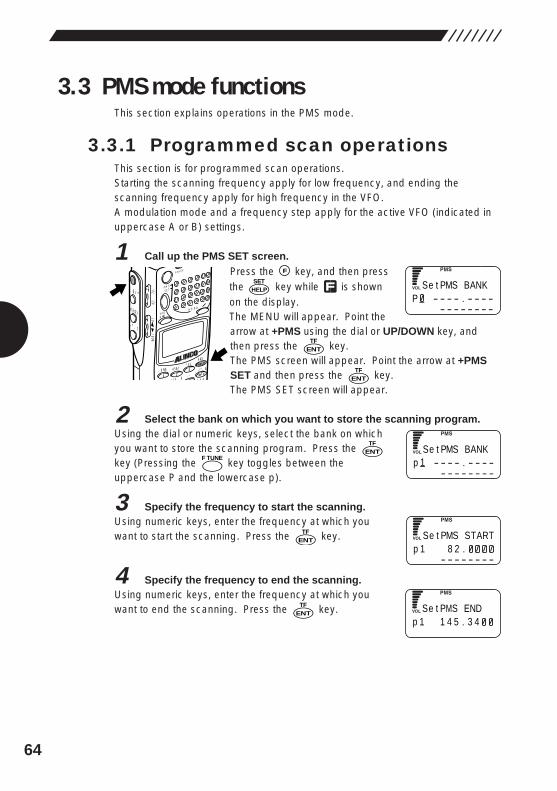
64
3.3 PMS mode functionsThis section explains operations in the PMS mode.
3.3.1 Programmed scan operationsThis section is for programmed scan operations.Starting the scanning frequency apply for low frequency, and ending thescanning frequency apply for high frequency in the VFO.A modulation mode and a frequency step apply for the active VFO (indicated inuppercase A or B) settings.
1 Call up the PMS SET screen.Press the key, and then pressthe key while is shownon the display.The MENU will appear. Point thearrow at +PMS using the dial or UP/DOWN key, andthen press the key.The PMS screen will appear. Point the arrow at +PMSSET and then press the key.The PMS SET screen will appear.
2 Select the bank on which you want to store the scanning program.Using the dial or numeric keys, select the bank on whichyou want to store the scanning program. Press the key (Pressing the key toggles between theuppercase P and the lowercase p).
3 Specify the frequency to start the scanning.Using numeric keys, enter the frequency at which youwant to start the scanning. Press the key.
4 Specify the frequency to end the scanning.Using numeric keys, enter the frequency at which youwant to end the scanning. Press the key.ENT
TF
ENTTF
F TUNEENT
TF
ENTTF
ENTTF
HELPSET
F
MODE
AUTO MW
MIC A-B S
M NAMESTEP
ATTSET
POWER
PMS
VFOMR MW
A B
SET
KL
�3
6
21 RF C
HELP
MONI
F
SRCH
LAMP
SQL VOL
DOWN UP
SP - - - - . - - - -
- - - - - - - -
e t PMS BANK
Sp 1 - - - - . - - - -
- - - - - - - -
e t PMS BANK
Sp 1 8 2 .
- - - - - - - -
e t PMS START
Sp 1 1 4 5 . 3 4
e t PMS END
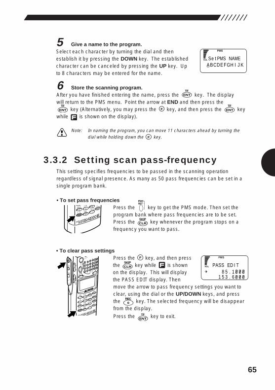
65
5 Give a name to the program.Select each character by turning the dial and thenestablish it by pressing the DOWN key. The establishedcharacter can be canceled by pressing the UP key. Upto 8 characters may be entered for the name.
6 Store the scanning program.After you have finished entering the name, press the key. The display will return to the PMS menu. Point the arrow at END and then press the
key (Alternatively, you may press the key, and then press the keywhile is shown on the display).
Note: In naming the program, you can move 11 characters ahead by turning thedial while holding down the key.
3.3.2 Setting scan pass-frequencyThis setting specifies frequencies to be passed in the scanning operationregardless of signal presence. As many as 50 pass frequencies can be set in asingle program bank.
• To set pass frequenciesPress the key to get the PMS mode. Then set theprogram bank where pass frequencies are to be set.Press the key whenever the program stops on afrequency you want to pass.
• To clear pass settingsPress the key, and then pressthe key while is shownon the display. This will displaythe PASS EDIT display. Thenmove the arrow to pass frequency settings you want toclear, using the dial or the UP/DOWN keys, and pressthe key. The selected frequency will be disappearfrom the display.
Press the key to exit.ENTTF
0REC
F
MODE
AUTO MW
INTELLIGENT
RECEIVERDJ-X2
MIC
SCRTPRIO
REC
CTCSS
F TUNE
A-B S
M NAME
TF
SKIP
STEPATT
SET
POWER
PMS
VFOMR MW
A B
SET
KL
�3
6
98
0
5
21
4
CLR
ENT
MIC
SCN
RF C
HELP
7
MONI
F
SRCH
LAMP
SQL VOL
DOWN UP
CLRSKIP
PMSSET
INTELLIGENT
RECEIVERDJ-X2
SCRTPRIO
REC
CT
F TUNETF
SKIP
98
0CLR
ENT
MIC
7
F
ENTTF
FENTTF
ENTTF
SA BCDE FGH I J K
e t PMS NAME
8 5 . 11 5 3 . 6
PASS ED I TCLRSKIP
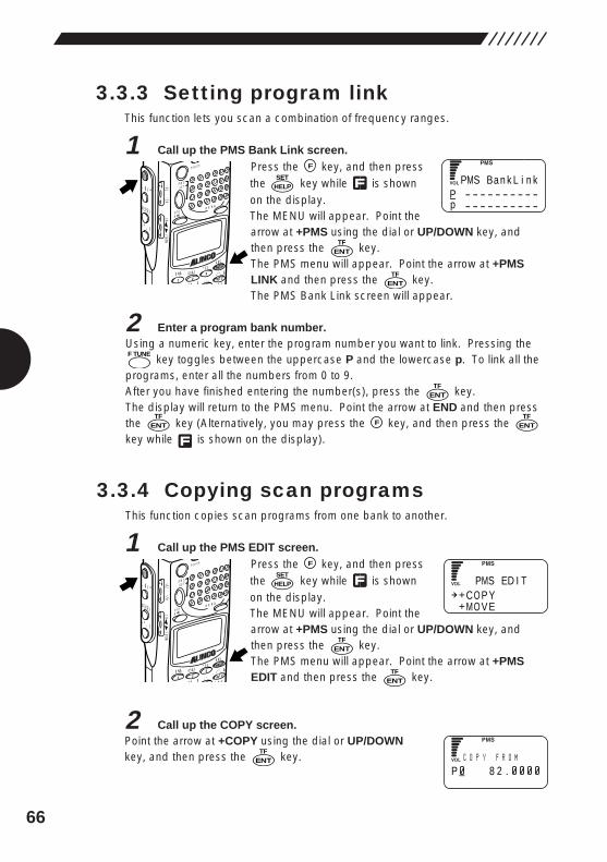
66
3.3.3 Setting program linkThis function lets you scan a combination of frequency ranges.
1 Call up the PMS Bank Link screen.Press the key, and then pressthe key while is shownon the display.The MENU will appear. Point thearrow at +PMS using the dial or UP/DOWN key, andthen press the key.The PMS menu will appear. Point the arrow at +PMSLINK and then press the key.The PMS Bank Link screen will appear.
2 Enter a program bank number.Using a numeric key, enter the program number you want to link. Pressing the
key toggles between the uppercase P and the lowercase p. To link all theprograms, enter all the numbers from 0 to 9.After you have finished entering the number(s), press the key.The display will return to the PMS menu. Point the arrow at END and then pressthe key (Alternatively, you may press the key, and then press the key while is shown on the display).
3.3.4 Copying scan programsThis function copies scan programs from one bank to another.
1 Call up the PMS EDIT screen.Press the key, and then pressthe key while is shownon the display.The MENU will appear. Point thearrow at +PMS using the dial or UP/DOWN key, andthen press the key.The PMS menu will appear. Point the arrow at +PMSEDIT and then press the key.
2 Call up the COPY screen.Point the arrow at +COPY using the dial or UP/DOWNkey, and then press the key.ENT
TF
ENTTF
ENTTF
HELPSET
F
MODE
AUTO MW
MIC A-B S
M NAMESTEP
ATTSET
POWER
PMS
VFOMR MW
A B
SET
KL
�3
6
21 RF C
HELP
MONI
F
SRCH
LAMP
SQL VOL
DOWN UP
ENTTF
FENTTF
ENTTF
F TUNE
ENTTF
ENTTF
HELPSET
F
MODE
AUTO MW
MIC A-B S
M NAMESTEP
ATTSET
POWER
PMS
VFOMR MW
A B
SET
KL
�3
6
21 RF C
HELP
MONI
F
SRCH
LAMP
SQL VOL
DOWN UP
PP - - - - - - - - - -p - - - - - - - - - -
MS Ba n k L i n k
CO P YMO V E
PMS ED I T
CP 8 2 .
O P Y F R OM
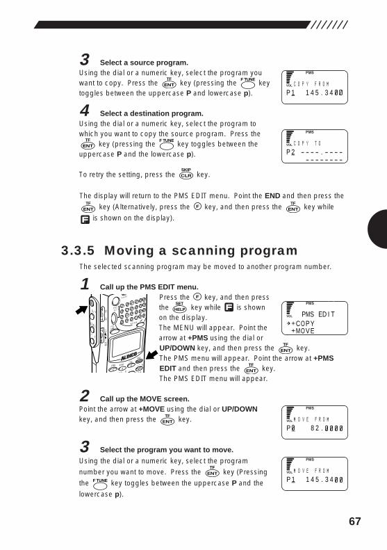
67
3 Select a source program.Using the dial or a numeric key, select the program youwant to copy. Press the key (pressing the keytoggles between the uppercase P and lowercase p).
4 Select a destination program.Using the dial or a numeric key, select the program towhich you want to copy the source program. Press the
key (pressing the key toggles between theuppercase P and the lowercase p).
To retry the setting, press the key.
The display will return to the PMS EDIT menu. Point the END and then press the
key (Alternatively, press the key, and then press the key while
is shown on the display).
3.3.5 Moving a scanning programThe selected scanning program may be moved to another program number.
1 Call up the PMS EDIT menu.Press the key, and then pressthe key while is shownon the display.The MENU will appear. Point thearrow at +PMS using the dial orUP/DOWN key, and then press the key.The PMS menu will appear. Point the arrow at +PMSEDIT and then press the key.The PMS EDIT menu will appear.
2 Call up the MOVE screen.Point the arrow at +MOVE using the dial or UP/DOWNkey, and then press the key.
3 Select the program you want to move.
Using the dial or a numeric key, select the program
number you want to move. Press the key (Pressing
the key toggles between the uppercase P and the
lowercase p).
F TUNE
ENTTF
ENTTF
ENTTF
ENTTF
HELPSET
F
MODE
AUTO MW
MIC A-B S
M NAMESTEP
ATTSET
POWER
PMS
VFOMR MW
A B
SET
KL
�3
6
21 RF C
HELP
MONI
F
SRCH
LAMP
SQL VOL
DOWN UP
ENTTF
FENT
TF
CLRSKIP
F TUNEENT
TF
F TUNEENT
TFC
P 1 1 4 5 . 3 4O P Y F R OM
CP 2 - - - - . - - - -
- - - - - - - -
O P Y T O
CO P YMO V E
PMS ED I T
MP 8 2 .
O V E F R OM
MP 1 1 4 5 . 3 4
O V E F R OM
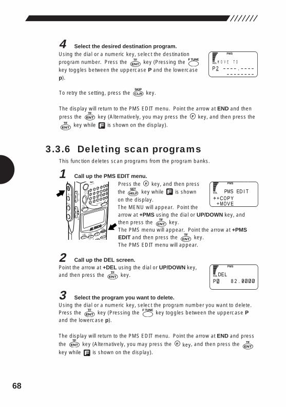
68
4 Select the desired destination program.Using the dial or a numeric key, select the destinationprogram number. Press the key (Pressing the key toggles between the uppercase P and the lowercasep).
To retry the setting, press the key.
The display will return to the PMS EDIT menu. Point the arrow at END and then
press the key (Alternatively, you may press the key, and then press the
key while is shown on the display).
3.3.6 Deleting scan programsThis function deletes scan programs from the program banks.
1 Call up the PMS EDIT menu.Press the key, and then pressthe key while is shownon the display.The MENU will appear. Point thearrow at +PMS using the dial or UP/DOWN key, andthen press the key.The PMS menu will appear. Point the arrow at +PMSEDIT and then press the key.The PMS EDIT menu will appear.
2 Call up the DEL screen.Point the arrow at +DEL using the dial or UP/DOWN key,and then press the key.
3 Select the program you want to delete.Using the dial or a numeric key, select the program number you want to delete.Press the key (Pressing the key toggles between the uppercase Pand the lowercase p).
The display will return to the PMS EDIT menu. Point the arrow at END and press
the key (Alternatively, you may press the key, and then press the
key while is shown on the display).ENT
TFFENTTF
F TUNEENT
TF
ENTTF
ENTTF
ENTTF
HELPSET
F
MODE
AUTO MW
MIC A-B S
M NAMESTEP
ATTSET
POWER
PMS
VFOMR MW
A B
SET
KL
�3
6
21 RF C
HELP
MONI
F
SRCH
LAMP
SQL VOL
DOWN UP
ENTTF
FENTTF
CLRSKIP
F TUNE
ENTTF M
P 2 - - - - . - - - -- - - - - - - -
O V E T O
CO P YMO V E
PMS ED I T
DP 8 2 .
EL
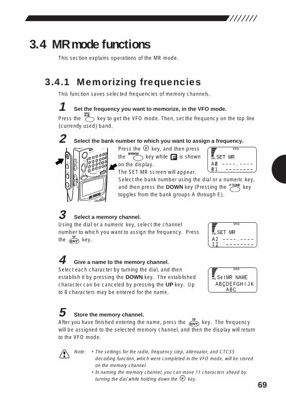
69
3.4 MR mode functionsThis section explains operations of the MR mode.
3.4.1 Memorizing frequenciesThis function saves selected frequencies of memory channels.
1 Set the frequency you want to memorize, in the VFO mode.
Press the key to get the VFO mode. Then, set the frequency on the top line(currently used) band.
2 Select the bank number to which you want to assign a frequency.Press the key, and then pressthe key while is shownon the display.The SET MR screen will appear.Select the bank number using the dial or a numeric key,and then press the DOWN key (Pressing the keytoggles from the bank groups A through E).
3 Select a memory channel.Using the dial or a numeric key, select the channelnumber to which you want to assign the frequency. Pressthe key.
4 Give a name to the memory channel.Select each character by turning the dial, and thenestablish it by pressing the DOWN key. The establishedcharacter can be canceled by pressing the UP key. Upto 8 characters may be entered for the name.
5 Store the memory channel.After you have finished entering the name, press the key. The frequencywill be assigned to the selected memory channel, and then the display will returnto the VFO mode.
Note: • The settings for the radio, frequency step, attenuator, and CTCSSdecoding function, which were completed in the VFO mode, will be storedon the memory channel.
• In naming the memory channel, you can move 11 characters ahead byturning the dial while holding down the key.F
ENTTF
ENTTF
F TUNE
MRMW
F
ODE NAMESTEPATT
SET
POWER
RX/ST
PMS
VFOMR MW
A B
SET
�HELP
MONI
F
SRCH
LAMP
SQL VOL
DOWN UP
A=BVFO
SA - - - - . - - - -
1 - - - - - - - -
ET MR
SA 2 - - - - . - - - -1 2 - - - - - - - -
ET MR
SA BCDE FGH I J K
A BC
e t MR NAME
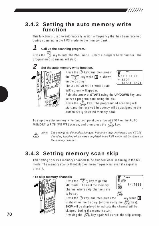
70
3.4.2 Setting the auto memory writefunction
This function is used to automatically assign a frequency that has been receivedduring scanning in the PMS mode, to the memory bank.
1 Call up the scanning program.
Press the key to enter the PMS mode. Select a program bank number. Theprogrammed scanning will start.
2 Set the auto memory write function.
Press the key, and then press
the key while is shown
on the display.
The AUTO MEMORY WRITE (MR
WR) screen will appear.Point the arrow at START using the UP/DOWN key, andselect a program bank using the dial.Press the key. The programmed scanning willstart and the received frequency will be assigned to theautomatically selected memory bank.
To stop the auto memory write function, point the arrow at STOP on the AUTOMEMORY WRITE (MR WR) screen, and then press the key.
Note: The settings for the modulation type, frequency step, attenuator, and CTCSSdecoding function, which were completed in the PMS mode, will be stored onthe memory channel.
3.4.3 Setting memory scan skipThis setting specifies memory channels to be skipped while scanning in the MRmode. The memory scan will not stop on these frequencies even if a signal ispresent.
• To skip memory channelsPress the key to get theMR mode. Then set the memorychannel where skip channels areto be set.
Press the key, and then press the key while is shown on the display. (or press only the key).SKIP will be displayed to indicate the channel will beskipped during the memory scan.Pressing the key again will cancel the skip setting.CLR
SKIP
CLRSKIP
F
MRMW
MODE
AUTO MW
INTELLIGENT
RECEIVERDJ-X2
MIC
SCRTPRIO
REC
CTCSS
F TUNE
A-B S
M NAME
TF
SKIP
STEPATT
SET
POWER
RX/ST
PMS
VFOMR MW
A B
SET
KL
�3
6
98
0
5
21
4
CLR
ENT
MIC
SCN
RF C
HELP
7
MONI
F
SRCH
LAMP
SQL VOL
DOWN U P
ENTTF
ENTTF
5AUTO MW
F
MODE
AUTO MW
MIC
CRTPRIO
CTCSSA-B S
M NAME
TF
STEPATT
SET
POWER
PMS
VFOMR MW
A B
SET
KL
�3
6
9
5
21
4SCN
RF C
HELP
MONI
F
SRCH
LAMP
SQL VOL
DOWN UP
PMSSET
AS T O PS T AR T A 9
U T O M R WR
WA 1 8 4 . 5
FM
CLRSKIP
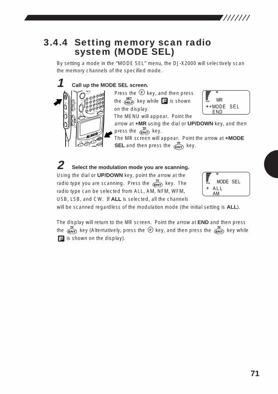
71
3.4.4 Setting memory scan radiosystem (MODE SEL)
By setting a mode in the “MODE SEL” menu, the DJ-X2000 will selectively scanthe memory channels of the specified mode.
1 Call up the MODE SEL screen.
Press the key, and then press
the key while is shown
on the display.The MENU will appear. Point thearrow at +MR using the dial or UP/DOWN key, and thenpress the key.The MR screen will appear. Point the arrow at +MODESEL and then press the key.
2 Select the modulation mode you are scanning.
Using the dial or UP/DOWN key, point the arrow at the
radio type you are scanning. Press the key. The
radio type can be selected from ALL, AM, NFM, WFM,
USB, LSB, and CW. If ALL is selected, all the channels
will be scanned regardless of the modulation mode (the initial setting is ALL).
The display will return to the MR screen. Point the arrow at END and then press
the key (Alternatively, press the key, and then press the key while
is shown on the display).ENT
TFFENT
TF
ENTTF
ENTTF
ENTTF
HELPSET
F
MODE
AUTO MW
MIC A-B S
M NAMESTEP
ATTSET
POWER
PMS
VFOMR MW
A B
SET
KL
�3
6
21 RF C
HELP
MONI
F
SRCH
LAMP
SQL VOL
DOWN UP
MODE S E LEND
MR
A L LAM
MODE SEL
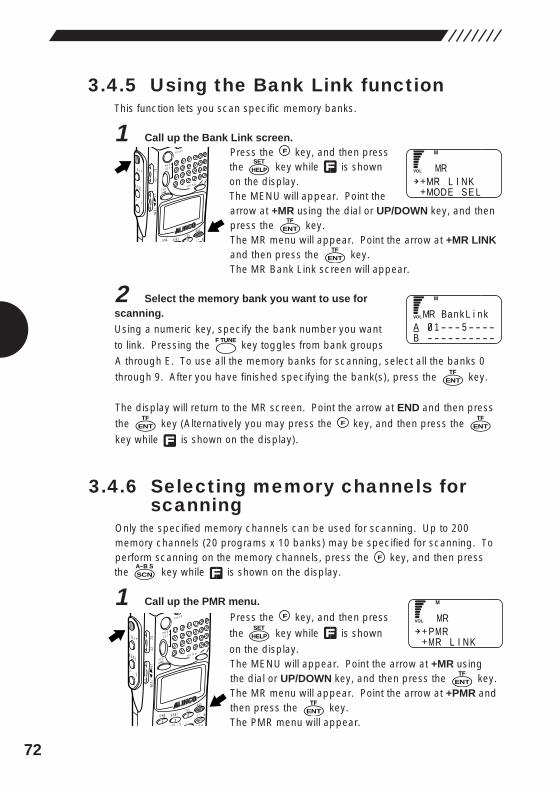
72
3.4.5 Using the Bank Link functionThis function lets you scan specific memory banks.
1 Call up the Bank Link screen.Press the key, and then pressthe key while is shownon the display.The MENU will appear. Point thearrow at +MR using the dial or UP/DOWN key, and thenpress the key.The MR menu will appear. Point the arrow at +MR LINKand then press the key.The MR Bank Link screen will appear.
2 Select the memory bank you want to use forscanning.
Using a numeric key, specify the bank number you want
to link. Pressing the key toggles from bank groups
A through E. To use all the memory banks for scanning, select all the banks 0
through 9. After you have finished specifying the bank(s), press the key.
The display will return to the MR screen. Point the arrow at END and then press
the key (Alternatively you may press the key, and then press the
key while is shown on the display).
3.4.6 Selecting memory channels forscanning
Only the specified memory channels can be used for scanning. Up to 200memory channels (20 programs x 10 banks) may be specified for scanning. Toperform scanning on the memory channels, press the key, and then pressthe key while is shown on the display.
1 Call up the PMR menu.
Press the key, and then press
the key while is shown
on the display.The MENU will appear. Point the arrow at +MR usingthe dial or UP/DOWN key, and then press the key.The MR menu will appear. Point the arrow at +PMR andthen press the key.The PMR menu will appear.
ENTTF
ENTTF
HELPSET
F
MODE
AUTO MW
MIC A-B S
M NAMESTEP
ATTSET
POWER
PMS
VFOMR MW
A B
SET
KL
�3
6
21 RF C
HELP
MONI
F
SRCH
LAMP
SQL VOL
DOWN UP
SCNA~B S
F
ENTTF
FENTTF
ENTTF
F TUNE
ENTTF
ENTTF
HELPSET
F
MODE M NAMESTEP
ATTSET
POWER
PMS
VFOMR MW
A B
SET
�3
HELP
MONI
F
SRCH
LAMP
SQL VOL
DOWN U P
MR L I NKMODE S E L
MR
MA 1 - - - 5 - - - -B - - - - - - - - - -
R Ba n k L i n k
PMRMR L I NK
MR
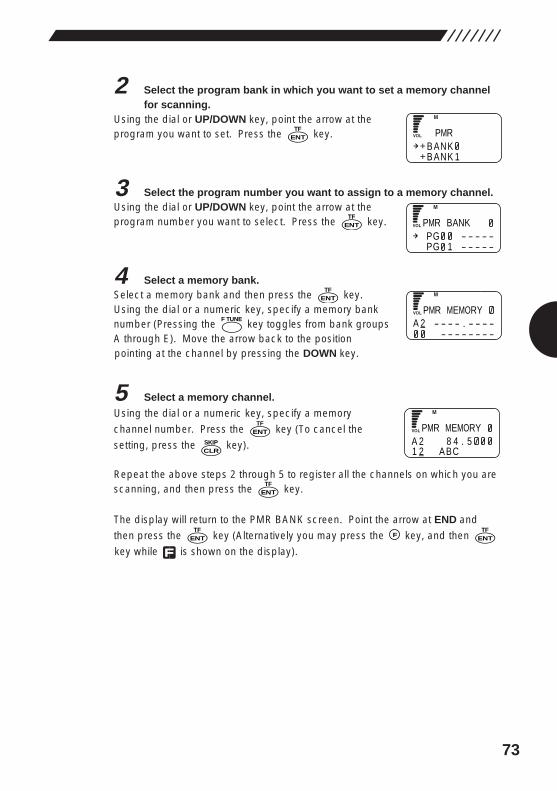
73
2 Select the program bank in which you want to set a memory channelfor scanning.
Using the dial or UP/DOWN key, point the arrow at theprogram you want to set. Press the key.
3 Select the program number you want to assign to a memory channel.Using the dial or UP/DOWN key, point the arrow at theprogram number you want to select. Press the key.
4 Select a memory bank.Select a memory bank and then press the key.Using the dial or a numeric key, specify a memory banknumber (Pressing the key toggles from bank groupsA through E). Move the arrow back to the positionpointing at the channel by pressing the DOWN key.
5 Select a memory channel.
Using the dial or a numeric key, specify a memory
channel number. Press the key (To cancel the
setting, press the key).
Repeat the above steps 2 through 5 to register all the channels on which you arescanning, and then press the key.
The display will return to the PMR BANK screen. Point the arrow at END and
then press the key (Alternatively you may press the key, and then
key while is shown on the display).ENT
TFFENT
TF
ENTTF
CLRSKIP
ENTTF
F TUNE
ENTTF
ENTTF
ENTTF
B ANKB ANK 1
PMR
PPG - - - - -PG 1 - - - - -
MR BANK
PA 2 - - - - . - - - -
- - - - - - - -
MR MEMORY
PA 2 8 4 . 51 2 A BC
MR MEMORY
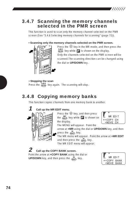
74
3.4.7 Scanning the memory channelsselected in the PMR screen
This function is used to scan only the memory channel selected on the PMRscreen (See “3.4.6 Selecting memory channels for scanning” (page 72)).
• Scanning only the memory channels selected on the PMR screen.
Press the key in the MR mode, and then press the
key while is shown on the display.
Only the channels selected on the PMR screen will be
scanned.The scanning direction can be changed using
the dial or UP/DOWN key.
• Stopping the scanPress the key again. The scanning will stop.
3.4.8 Copying memory banksThis function copies channels from one memory bank to another.
1 Call up the MR EDIT menu.
Press the key, and then press
the key while is shown on
the display.The MENU will appear. Point thearrow at +MR using the dial or UP/DOWN key, and thenpress the key.The MR menu will appear. Point the arrow at +MR EDITand then press the key.The MR EDIT menu will appear.
2 Call up the COPY BANK screen.Point the arrow at +COPY BANK using the dial orUP/DOWN key, and then press the key.ENT
TF
ENTTF
ENTTF
HELPSET
F
MODE
AUTO MW
MIC A-B S
M NAMESTEP
ATTSET
POWER
PMS
VFOMR MW
A B
SET
KL
�3
6
21 RF C
HELP
MONI
F
SRCH
LAMP
SQL VOL
DOWN UP
SCNA~B S
SCNA~B S
F
MODE
AUTO MW
MIC
SCRTPRIO
CTCSSA-B S
M NAME
TF
STEPATT
SET
POWER
RX/ST
PMS
VFOMR MW
A B
SET
KL
�3
6
9
5
21
4SCN
RF C
HELP
MONI
F
SRCH
LAMP
SQL VOL
DOWN UP
COP Y CHMOV E CH
MR ED I T
COP Y B ANKMOV E B ANK
MR ED I T
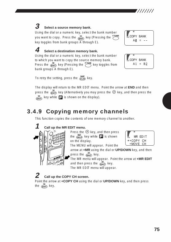
75
3 Select a source memory bank.
Using the dial or a numeric key, select the bank number
you want to copy. Press the key (Pressing the
key toggles from bank groups A through E).
4 Select a destination memory bank.Using the dial or a numeric key, select the bank numberto which you want to copy the source memory bank.Press the key (Pressing the key toggles frombank groups A through E).
To retry the setting, press the key.
The display will return to the MR EDIT menu. Point the arrow at END and then
press the key (Alternatively you may press the key, and then press the
key while is shown on the display).
3.4.9 Copying memory channelsThis function copies the contents of one memory channel to another.
1 Call up the MR EDIT menu.Press the key, and then pressthe key while is shownon the display.The MENU will appear. Point thearrow at +MR using the dial or UP/DOWN key, and thenpress the key.The MR menu will appear. Point the arrow at +MR EDITand then press the key.The MR EDIT menu will appear.
2 Call up the COPY CH screen.Point the arrow at +COPY CH using the dial or UP/DOWN key, and then pressthe key.ENT
TF
ENTTF
ENTTF
HELPSET
F
MODE
AUTO MW
MIC A-B S
M NAMESTEP
ATTSET
POWER
PMS
VFOMR MW
A B
SET
KL
�3
6
21 RF C
HELP
MONI
F
SRCH
LAMP
SQL VOL
DOWN UP
ENTTF
FENTTF
CLRSKIP
F TUNEENT
TF
F TUNE
ENTTF C
A = - -OPY BANK
CA 1 = B 2
OPY BANK
COP Y CHMOV E CH
MR ED I T
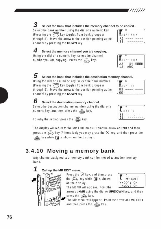
76
3 Select the bank that includes the memory channel to be copied.Select the bank number using the dial or a numeric key(Pressing the key toggles from bank groups Athrough E). Move the arrow to the position pointing at thechannel by pressing the DOWN key.
4 Select the memory channel you are copying.Using the dial or a numeric key, select the channelnumber you are copying. Press the key.
5 Select the bank that includes the destination memory channel.Using the dial or a numeric key, select the bank number(Pressing the key toggles from bank groups Athrough E). Move the arrow to the position pointing at thechannel by pressing the DOWN key.
6 Select the destination memory channel.Select the destination channel number using the dial or anumeric key, and then press the key.
To retry the setting, press the key.
The display will return to the MR EDIT menu. Point the arrow at END and then
press the key (Alternatively you may press the key, and then press the
key while is shown on the display).
3.4.10 Moving a memory bankAny channel assigned to a memory bank can be moved to another memorybank.
1 Call up the MR EDIT menu.Press the key, and then pressthe key while is shownon the display.The MENU will appear. Point thearrow at +MR using the dial or UP/DOWN key, and thenpress the key.The MR menu will appear. Point the arrow at +MR EDITand then press the key.ENT
TF
ENTTF
HELPSET
F
MODE
AUTO MW
MIC A-B S
M NAMESTEP
ATTSET
POWER
PMS
VFOMR MW
A B
SET
KL
�3
6
21 RF C
HELP
MONI
F
SRCH
LAMP
SQL VOL
DOWN UP
ENTTF
FENTTF
CLRSKIP
ENTTF
F TUNE
ENTTF
F TUNEC
A 2 - - - - . - - - -- - - - - - - -
O P Y F R OM
CA 2 8 4 . 51 2 A BC
O P Y F R OM
CB 3 - - - - . - - - -
- - - - - - - -
O P Y T O
CB 3 - - - - . - - - -
5 - - - - - - - -
O P Y T O
COP Y CHMOV E CH
MR ED I T
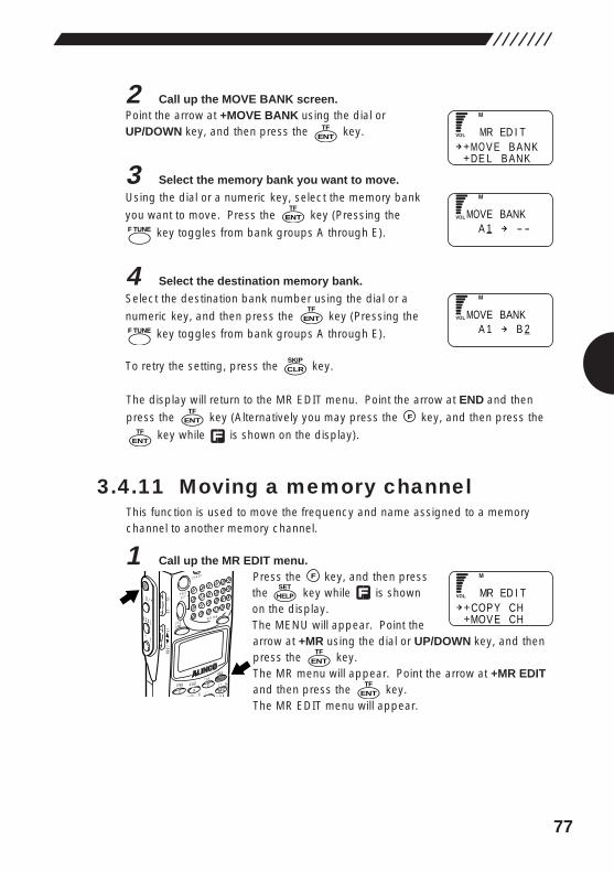
77
2 Call up the MOVE BANK screen.Point the arrow at +MOVE BANK using the dial orUP/DOWN key, and then press the key.
3 Select the memory bank you want to move.
Using the dial or a numeric key, select the memory bank
you want to move. Press the key (Pressing the
key toggles from bank groups A through E).
4 Select the destination memory bank.
Select the destination bank number using the dial or a
numeric key, and then press the key (Pressing the
key toggles from bank groups A through E).
To retry the setting, press the key.
The display will return to the MR EDIT menu. Point the arrow at END and then
press the key (Alternatively you may press the key, and then press the
key while is shown on the display).
3.4.11 Moving a memory channelThis function is used to move the frequency and name assigned to a memorychannel to another memory channel.
1 Call up the MR EDIT menu.Press the key, and then pressthe key while is shownon the display.The MENU will appear. Point thearrow at +MR using the dial or UP/DOWN key, and thenpress the key.The MR menu will appear. Point the arrow at +MR EDITand then press the key.The MR EDIT menu will appear.
ENTTF
ENTTF
HELPSET
F
MODE
AUTO MW
MIC A-B S
M NAMESTEP
ATTSET
POWER
PMS
VFOMR MW
A B
SET
KL
�3
6
21 RF C
HELP
MONI
F
SRCH
LAMP
SQL VOL
DOWN UP
ENTTF
FENTTF
CLRSKIP
F TUNE
ENTTF
F TUNE
ENTTF
ENTTF
MO V E B ANKDE L B ANK
MR ED I T
MA 1 - -
OVE BANK
MA 1 B 2
OVE BANK
COP Y CHMOV E CH
MR ED I T
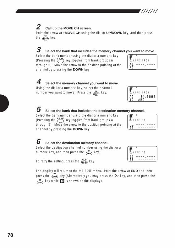
78
2 Call up the MOVE CH screen.Point the arrow at +MOVE CH using the dial or UP/DOWN key, and then pressthe key.
3 Select the bank that includes the memory channel you want to move.Select the bank number using the dial or a numeric key(Pressing the key toggles from bank groups Athrough E). Move the arrow to the position pointing at thechannel by pressing the DOWN key.
4 Select the memory channel you want to move.Using the dial or a numeric key, select the channelnumber you want to move. Press the key.
5 Select the bank that includes the destination memory channel.Select the bank number using the dial or a numeric key(Pressing the key toggles from bank groups Athrough E). Move the arrow to the position pointing at thechannel by pressing the DOWN key.
6 Select the destination memory channel.Select the destination channel number using the dial or anumeric key, and then press the key.
To retry the setting, press the key.
The display will return to the MR EDIT menu. Point the arrow at END and then
press the key (Alternatively you may press the key, and then press the
key while is shown on the display).ENT
TF
FENTTF
CLRSKIP
ENTTF
F TUNE
ENTTF
F TUNE
ENTTF
MA 2 - - - - . - - - -
- - - - - - - -
O V E F R OM
MA 2 8 4 . 51 2 A BC
O V E F R OM
MB 3 - - - - . - - - -
- - - - - - - -
O V E T O
MB 3 - - - - . - - - -
5 - - - - - - - -
O V E T O
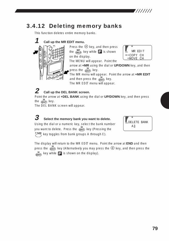
79
3.4.12 Deleting memory banksThis function deletes entire memory banks.
1 Call up the MR EDIT menu.
Press the key, and then press
the key while is shown
on the display.The MENU will appear. Point thearrow at +MR using the dial or UP/DOWN key, and thenpress the key.The MR menu will appear. Point the arrow at +MR EDITand then press the key.The MR EDIT menu will appear.
2 Call up the DEL BANK screen.Point the arrow at +DEL BANK using the dial or UP/DOWN key, and then pressthe key.The DEL BANK screen will appear.
3 Select the memory bank you want to delete.
Using the dial or a numeric key, select the bank number
you want to delete. Press the key (Pressing the
key toggles from bank groups A through E).
The display will return to the MR EDIT menu. Point the arrow at END and then
press the key (Alternatively you may press the key, and then press the
key while is shown on the display).ENT
TF
FENTTF
F TUNE
ENTTF
ENTTF
ENTTF
ENTTF
HELPSET
F
MODE
AUTO MW
MIC A-B S
M NAMESTEP
ATTSET
POWER
PMS
VFOMR MW
A B
SET
KL
�3
6
21 RF C
HELP
MONI
F
SRCH
LAMP
SQL VOL
DOWN UP
COP Y CHMOV E CH
MR ED I T
DA 3
ELETE BANK
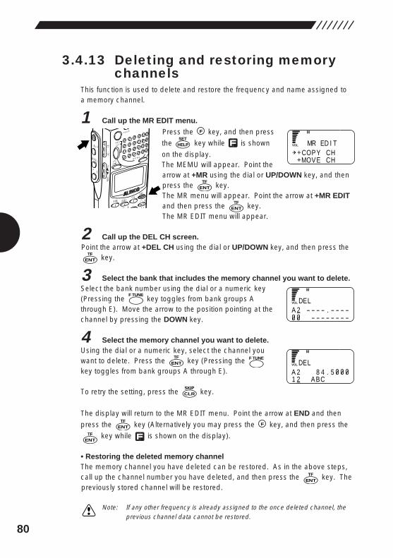
80
3.4.13 Deleting and restoring memorychannels
This function is used to delete and restore the frequency and name assigned toa memory channel.
1 Call up the MR EDIT menu.
Press the key, and then press
the key while is shown
on the display.The MEMU will appear. Point thearrow at +MR using the dial or UP/DOWN key, and thenpress the key.The MR menu will appear. Point the arrow at +MR EDITand then press the key.The MR EDIT menu will appear.
2 Call up the DEL CH screen.Point the arrow at +DEL CH using the dial or UP/DOWN key, and then press the
key.
3 Select the bank that includes the memory channel you want to delete.Select the bank number using the dial or a numeric key(Pressing the key toggles from bank groups Athrough E). Move the arrow to the position pointing at thechannel by pressing the DOWN key.
4 Select the memory channel you want to delete.Using the dial or a numeric key, select the channel youwant to delete. Press the key (Pressing the key toggles from bank groups A through E).
To retry the setting, press the key.
The display will return to the MR EDIT menu. Point the arrow at END and then
press the key (Alternatively you may press the key, and then press the
key while is shown on the display).
• Restoring the deleted memory channelThe memory channel you have deleted can be restored. As in the above steps,call up the channel number you have deleted, and then press the key. Thepreviously stored channel will be restored.
Note: If any other frequency is already assigned to the once deleted channel, theprevious channel data cannot be restored.
ENTTF
ENTTF
FENT
TF
CLRSKIP
F TUNEENT
TF
F TUNE
ENTTF
ENTTF
ENTTF
HELPSET
F
MODE
AUTO MW
MIC A-B S
M NAMESTEP
ATTSET
POWER
PMS
VFOMR MW
A B
SET
KL
�3
6
21 RF C
HELP
MONI
F
SRCH
LAMP
SQL VOL
DOWN UP
COP Y CHMOV E CH
MR ED I T
DA 2 - - - - . - - - -
- - - - - - - -
EL
DA 2 8 4 . 51 2 A BC
EL
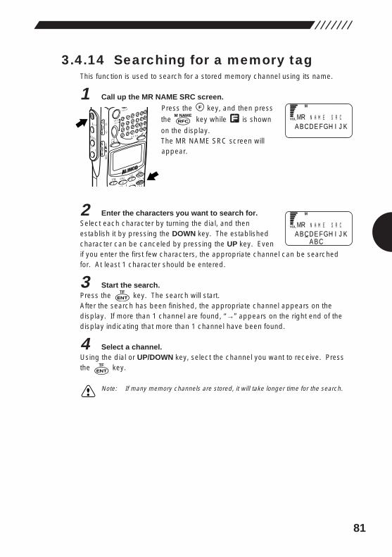
81
3.4.14 Searching for a memory tagThis function is used to search for a stored memory channel using its name.
1 Call up the MR NAME SRC screen.
Press the key, and then press
the key while is shown
on the display.The MR NAME SRC screen willappear.
2 Enter the characters you want to search for.Select each character by turning the dial, and thenestablish it by pressing the DOWN key. The establishedcharacter can be canceled by pressing the UP key. Evenif you enter the first few characters, the appropriate channel can be searchedfor. At least 1 character should be entered.
3 Start the search.Press the key. The search will start.After the search has been finished, the appropriate channel appears on thedisplay. If more than 1 channel are found, “→” appears on the right end of thedisplay indicating that more than 1 channel have been found.
4 Select a channel.Using the dial or UP/DOWN key, select the channel you want to receive. Pressthe key.
Note: If many memory channels are stored, it will take longer time for the search.
ENTTF
ENTTF
RFCM NAME
F
MODE
AUTO MW
MIC A-B S
M NAMESTEP
ATTSET
POWER
PMS
VFOMR MW
A B
SET
KL
�3
6
21 RF C
HELP
MONI
F
SRCH
LAMP
SQL VOL
DOWN UP
MA BCDE FGH I J K
R N AM E S R C
MA BCDE FGH I J K
A BC
R N AM E S R C
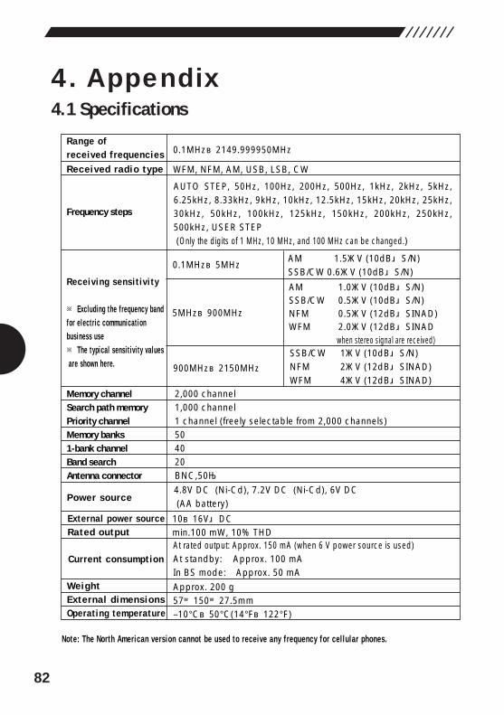
82
4. Appendix4.1 Specifications
Range of received frequenciesReceived radio type
Memory channelSearch path memoryPriority channelMemory banks1-bank channelBand searchAntenna connector
Frequency steps
Receiving sensit iv i ty
※ Excluding the frequency band for electr ic communication business use※ The typical sensit iv i ty values are shown here.
0.1MHz~2149.999950MHz
WFM, NFM, AM, USB, LSB, CW
2,000 channel1,000 channel1 channel (freely selectable from 2,000 channels)504020BNC,50Ω
AUTO STEP, 50Hz, 100Hz, 200Hz, 500Hz, 1kHz, 2kHz, 5kHz, 6.25kHz, 8.33kHz, 9kHz, 10kHz, 12.5kHz, 15kHz, 20kHz, 25kHz, 30kHz, 50kHz, 100kHz, 125kHz, 150kHz, 200kHz, 250kHz, 500kHz, USER STEP (Only the digits of 1 MHz, 10 MHz, and 100 MHz can be changed.)
0.1MHz~5MHzAM 1.5μV (10dB S/N)SSB/CW 0.6μV (10dB S/N)
5MHz~900MHz
AM 1.0μV (10dB S/N)SSB/CW 0.5μV (10dB S/N)NFM 0.5μV (12dB SINAD)WFM 2.0μV (12dB SINAD
when stereo signal are received)
900MHz~2150MHz
SSB/CW 1μV (10dB S/N)NFM 2μV (12dB SINAD)WFM 4μV (12dB SINAD)
Approx. 200 g57×150×27.5mm–10°C~50°C(14°F~122°F)
4.8V DC (Ni-Cd), 7.2V DC (Ni-Cd), 6V DC (AA battery)
10~16V DCmin.100 mW, 10% THDAt rated output: Approx. 150 mA (when 6 V power source is used)At standby: Approx. 100 mAIn BS mode: Approx. 50 mA
WeightExternal dimensionsOperating temperature
Power source
External power sourceRated output
Current consumption
Note: The North American version cannot be used to receive any frequency for cel lular phones.
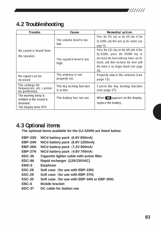
83
4.2 Troubleshooting
4.3 Optional itemsThe optional items available for the DJ-X2000 are listed below:
EBP-33N NiCd battery pack (4.8V 650mA)EBP-34N NiCd battery pack (4.8V 1200mA)EBP-35N NiCd battery pack (7.2V 900mA)EBP-37N NiCd battery pack (4.8V 700mA)EDC-36 Cigarette lighter cable with active filterEDC-88 Rapid recharger (120/230VAC)EME-6 EarphoneESC-28 Soft case (for use with EBP-33N)ESC-29 Soft case (for use with EBP-37N)ESC-30 Soft case (for use with EBP-34N or EBP-35N)EBC-6 Mobile bracketEDC-37 DC cable for station use
Trouble Cause Remedial action
No sound is heard from
the speaker.
No signal can be received.
The settings for frequencies, etc. cannot be performed.The warning beep is emitted or the sound is distorted. The display turns OFF.
The volume level is too low.
The squelch level is too high.
The antenna is not properly set.
The key locking function is active.
The battery has run out.
Press the VOL key on the left side of the DJ-X2000, and then turn up the volume (see page 19).Press the SQL key on the left side of the DJ-X2000, press the DOWN key to decrease the level until any noise can be heard, and then increase the level until the noise is no longer heard (see page 20).Properly attach the antenna (see page 13).
Cancel the key locking function (see page 27).
When appears on the display,
replace the battery.
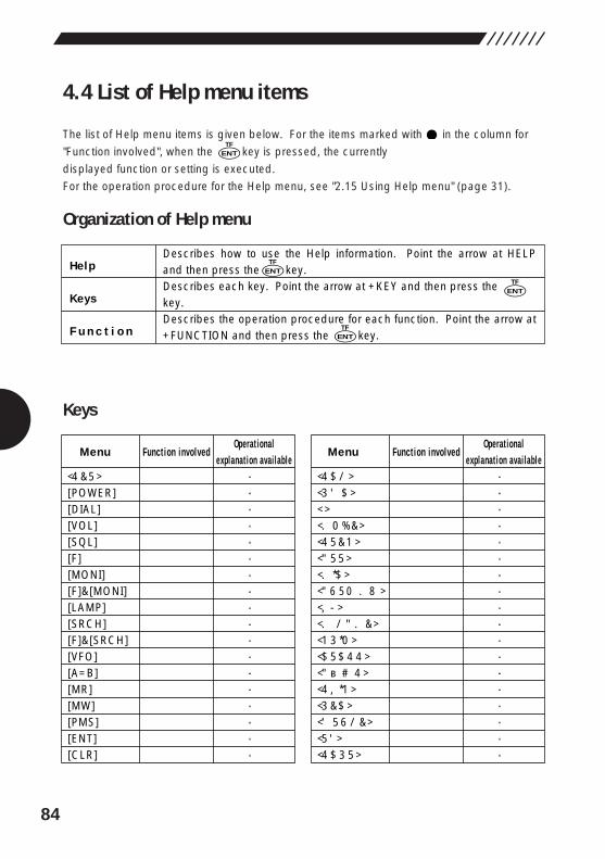
84
4.4 List of Help menu items
The list of Help menu items is given below. For the items marked with in the column for
"Function involved", when the key is pressed, the currently
displayed function or setting is executed.
For the operation procedure for the Help menu, see "2.15 Using Help menu" (page 31).
Organization of Help menu
Keys
ENTTF
Describes how to use the Help information. Point the arrow at HELP and then press the key.Describes each key. Point the arrow at +KEY and then press the key.Describes the operation procedure for each function. Point the arrow at +FUNCTION and then press the key.
Help
Keys
F u n c t i o n
ENTTF
ENTTF
ENTTF
Operational explanation avai lable
●�●�●�●�●�●�●�●�●�●�●�●�●�●�●�●�●�●�
Operational explanation avai lable
●●●●●●●●●●●●●●●●●●
Menu
[SET]� [POWER][DIAL][VOL][SQL][F][MONI][F]&[MONI][LAMP][SRCH][F]&[SRCH][VFO][A=B][MR][MW][PMS][ENT][CLR]
Function involved Function involved Menu
[SCN]� [RF C]� [.]� [MODE]� [STEP]� [ATT]� [MIC]� [AUTO MW]� [KL]� [M NAME]� [PRIO]� [CTCSS]� [A~B S]� [SKIP]� [REC]� [F TUNE]� [TF]� [SCRT]
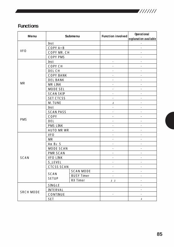
85
Functions
Menu Submenu Function involved��
Operational explanation avai lable
InstCOPY A=BCOPY MR. CHCOPY PMSInstCOPY CHDEL CHCOPY BANKDEL BANKMR LINKMODE SELSCAN SKIPSET CTCSSM. TUNEInstSCAN PASSCOPYDELPMS LINKAUTO MR WRVFOMRA~B SMODE SCANPMR SCANVFO LINKS_LEVELCTCSS SCAN
SCANSETUP
SINGLEINTERVALCONTINUESET
SCAN MODEBUSY TimerRX Timer
SRCH MODE
SCAN
PMS
MR
VFO
●�●�●�●�●�●�●�●�●�●�●�●�●�●�●�●�●�●�●�●�●�●�●�●�●�●�●�●�●�●�●�●�●�●� �
����●�●�●�●�●�●�●�●�●� �●�●�●�●�●�●�●�●�●�●�●�●�●�●�●�●� ���●��
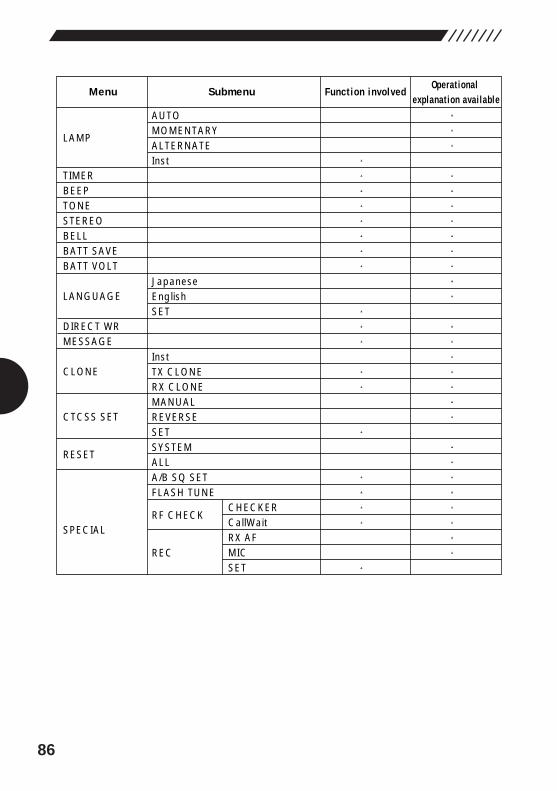
86
Function involvedMenu SubmenuOperational
explanation avai lableAUTOMOMENTARYALTERNATEInst
JapaneseEnglishSET
InstTX CLONERX CLONEMANUALREVERSESETSYSTEMALLA/B SQ SETFLASH TUNE
RF CHECK
REC
�
LAMP
TIMERBEEPTONESTEREOBELLBATT SAVEBATT VOLT
LANGUAGE
DIRECT WRMESSAGE
CLONE
CTCSS SET
RESET
SPECIAL
●�●�●��●�●�●�●�●�●�●�●�●��●�●�●�●�●�●�●��●�●�●�●�●�●�●�●��
●●●●●●●●
●●●
●●
●
●●●●
●
CHECKERCallWaitRX AFMICSET

Office: "TWIN 21" MID Tower Building 25F1-61, 2-chome, Shiromi, Chuo-ku, Osaka, 540-8580, JAPANPhone: 06-6946-8150 Fax: 06-6946-8175E-mail: [email protected]
Copyright 2000, Alinco,Inc. Osaka JapanPrinted in Japan PS0364A