WI-125 Indicator Series User’s Manual WI-125 Indicator Series User's Manual ... Push Button Zero...
20
WI-125 Indicator Series User’s Manual
Transcript of WI-125 Indicator Series User’s Manual WI-125 Indicator Series User's Manual ... Push Button Zero...

WI-125 Indicator SeriesUser’s Manual
2 WI-125 Indicator Series User's Manual03/05/03 125GRP_U.P65 PN 29559-0012i e2 Printed in USA
Risk of electrical shock. Do not remove cover. No user service-able parts inside. Refer servicing to qualified service personnel.
Weigh-Tronix reserves the right to changespecifications at any time.
CAUTION
3WI-125 Indicator Series User's Manual
Table of Contents
Introduction ................................................................................................5
Operations Mode........................................................................................5
Keyboard ....................................................................................................5
Key Functions .......................................................................................6Entering Numbers with Arrow Keys ......................................................6
Indicator Operation.....................................................................................7
Powering Up .........................................................................................7Annunciators .........................................................................................7Operations Menu ..................................................................................8Gross/Tare/Net Weighing Operations...................................................8
Gross Weighing ...............................................................................8Net Weighing ...................................................................................9
Pushbutton Tare ........................................................................9Entering a Scroll Tare ................................................................9Clearing the Active Tare ..........................................................10Net Weighing Operation...........................................................10
ID Number Entry .................................................................................10Viewing and Setting Time (Option) .....................................................11Viewing and Setting Date (Option)......................................................11Single Accumulator with Counter ........................................................12
Viewing Accumulated Weight and Count ......................................13Enabling or Disabling Display Backlight ..............................................13
Indicator Diagnostics ................................................................................14Test Mode ...........................................................................................14
Wiring Connections ..................................................................................15Pin Assignments .................................................................................15
Transmitting Data .....................................................................................17Communication Protocol .....................................................................18
Pages are numbered consecutively beginning with the cover page.
4 WI-125 Indicator Series User's Manual
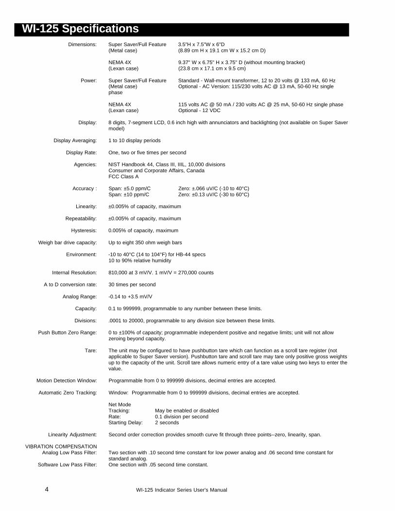
WI-125 SpecificationsDimensions: Super Saver/Full Feature 3.5"H x 7.5"W x 6"D
(Metal case) (8.89 cm H x 19.1 cm W x 15.2 cm D)
NEMA 4X 9.37" W x 6.75" H x 3.75" D (without mounting bracket)(Lexan case) (23.8 cm x 17.1 cm x 9.5 cm)
Power: Super Saver/Full Feature Standard - Wall-mount transformer, 12 to 20 volts @ 133 mA, 60 Hz(Metal case) Optional - AC Version: 115/230 volts AC @ 13 mA, 50-60 Hz singlephase
NEMA 4X 115 volts AC @ 50 mA / 230 volts AC @ 25 mA, 50-60 Hz single phase(Lexan case) Optional - 12 VDC
Display: 8 digits, 7-segment LCD, 0.6 inch high with annunciators and backlighting (not available on Super Savermodel)
Display Averaging: 1 to 10 display periods
Display Rate: One, two or five times per second
Agencies: NIST Handbook 44, Class III, IIIL, 10,000 divisionsConsumer and Corporate Affairs, CanadaFCC Class A
Accuracy : Span: ±5.0 ppm/C Zero: ±.066 uV/C (-10 to 40°C)Span: ±10 ppm/C Zero: ±0.13 uV/C (-30 to 60°C)
Linearity: ±0.005% of capacity, maximum
Repeatability: ±0.005% of capacity, maximum
Hysteresis: 0.005% of capacity, maximum
Weigh bar drive capacity: Up to eight 350 ohm weigh bars
Environment: -10 to 40°C (14 to 104°F) for HB-44 specs10 to 90% relative humidity
Internal Resolution: 810,000 at 3 mV/V. 1 mV/V = 270,000 counts
A to D conversion rate: 30 times per second
Analog Range: -0.14 to +3.5 mV/V
Capacity: 0.1 to 999999, programmable to any number between these limits.
Divisions: .0001 to 20000, programmable to any division size between these limits.
Push Button Zero Range: 0 to ±100% of capacity; programmable independent positive and negative limits; unit will not allowzeroing beyond capacity.
Tare: The unit may be configured to have pushbutton tare which can function as a scroll tare register (notapplicable to Super Saver version). Pushbutton tare and scroll tare may tare only positive gross weightsup to the capacity of the unit. Scroll tare allows numeric entry of a tare value using two keys to enter thevalue.
Motion Detection Window: Programmable from 0 to 999999 divisions, decimal entries are accepted.
Automatic Zero Tracking: Window: Programmable from 0 to 999999 divisions, decimal entries are accepted.
Net ModeTracking: May be enabled or disabledRate: 0.1 division per secondStarting Delay: 2 seconds
Linearity Adjustment: Second order correction provides smooth curve fit through three points--zero, linearity, span.
VIBRATION COMPENSATIONAnalog Low Pass Filter: Two section with .10 second time constant for low power analog and .06 second time constant for
standard analog.Software Low Pass Filter: One section with .05 second time constant.
5WI-125 Indicator Series User's Manual
Introduction
Operations Mode
Keyboard
The WI-125 Indicator comes in three versions: the Super Saver, Full Fea-ture, and NEMA 4X. The WI-125 Super Saver is a simple weight indicatorwhich includes push-button tare. The WI-125 Full Feature is a full-functionweight indicator with backlight display, RS-232 serial output and scroll tare.The WI-125 NEMA 4X Indicator is a full feature model enclosed in a NEMAIV Lexan case.
This set of instructions is divided into the following sections:
• Introduction• Operations Mode• Keyboard• Indicator Operation• Indicator Diagnostics• Wiring Connections• Transmitting Data• Specifications
Operations mode contains all normal weighing operations. In this mode youcan view or set the following parameters if the unit is so configured:
• pushbutton tare or scroll tare*• identification entry*• time*• date*• backlight*
Time, date and backlight can be secured behind a security code. Param-eters secured by the code number can be viewed but not changed unlessyou enter the security code.
*Scroll tare, id, time, date and backlight are not available on the Super Savermodel.
The keyboard consists of 7 keys. Five keys, or buttons, provide all the basicweighing functions:
• Tare• Gross/Net• Zero• Print• Units
The other keys are used to access the menus for purposes of accessinginformation, testing the indicator, and configuration. The keyboard is shownin Figure 1.
6 WI-125 Indicator Series User's Manual
Entering Numbers withArrow Keys
If at any time you enter anincorrect number, pressCLEAR to delete the number,then re-key.
Key Functions
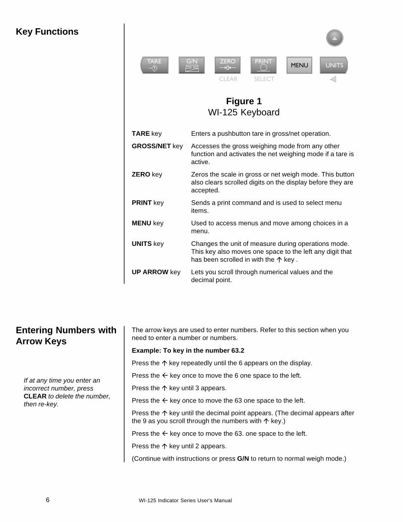
Figure 1WI-125 Keyboard
TARE key Enters a pushbutton tare in gross/net operation.
GROSS/NET key Accesses the gross weighing mode from any otherfunction and activates the net weighing mode if a tare isactive.
ZERO key Zeros the scale in gross or net weigh mode. This buttonalso clears scrolled digits on the display before they areaccepted.
PRINT key Sends a print command and is used to select menuitems.
MENU key Used to access menus and move among choices in amenu.
UNITS key Changes the unit of measure during operations mode.This key also moves one space to the left any digit thathas been scrolled in with the � key .
UP ARROW key Lets you scroll through numerical values and thedecimal point.
The arrow keys are used to enter numbers. Refer to this section when youneed to enter a number or numbers.
Example: To key in the number 63.2
Press the � key repeatedly until the 6 appears on the display.
Press the � key once to move the 6 one space to the left.
Press the � key until 3 appears.
Press the � key once to move the 63 one space to the left.
Press the � key until the decimal point appears. (The decimal appears afterthe 9 as you scroll through the numbers with � key.)
Press the � key once to move the 63. one space to the left.
Press the � key until 2 appears.
(Continue with instructions or press G/N to return to normal weigh mode.)
7WI-125 Indicator Series User's Manual
Annunciators
No annunciators appear whilemotion is detected.
Indicator OperationThe unit will power up in gross or net weighing mode, depending on whatmode the unit was in when last turned off. All calibration, zero, gross, andtare values will be maintained during power loss.
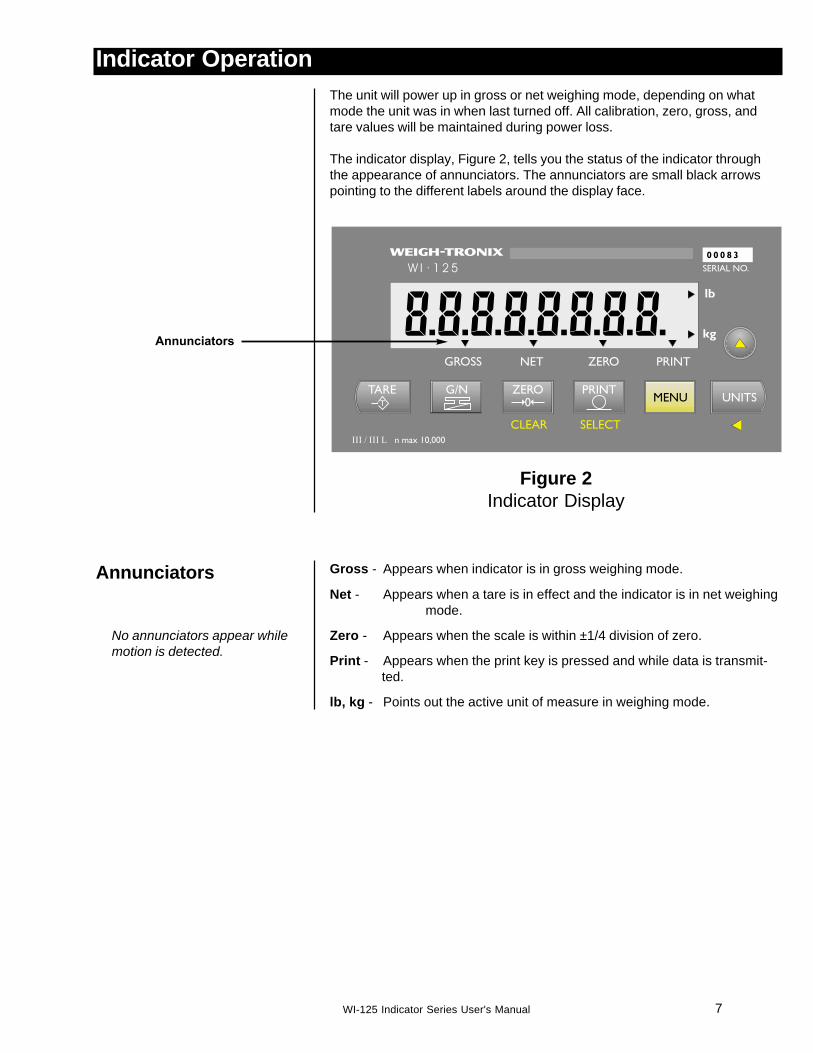
The indicator display, Figure 2, tells you the status of the indicator throughthe appearance of annunciators. The annunciators are small black arrowspointing to the different labels around the display face.
Figure 2Indicator Display
Gross - Appears when indicator is in gross weighing mode.
Net - Appears when a tare is in effect and the indicator is in net weighingmode.
Zero - Appears when the scale is within ±1/4 division of zero.
Print - Appears when the print key is pressed and while data is transmit-ted.
lb, kg - Points out the active unit of measure in weighing mode.

8 WI-125 Indicator Series User's Manual
Operations Menu
Gross / Tare / NetWeighing Operations
Gross Weighing
Depending on your model of WI-125 and firmware revision level, your unitmay be configured to display some or all of the following functions: pushbut-ton tare, time, date, accumulator, counter and backlight. These can beviewed and changed if allowed by the security code. This manual assumesthe unit is configured to allow full access to all functions. You candisable unneeded options. Instructions are in the Service Manual. Below is aflowchart and general instructions for moving around the operations modemenu.
Figure 3Operations Menu Diagram
Press MENU to go right in the diagram
Press and hold MENU to go left in the diagram
Press SELECT to go up and down in the diagram
Press SELECT to select new choice and go up in the diagram
Press G/N at any time to save changes and return to gross/net weighingmode
To perform gross/net weighing operations, follow these steps:
1. Power up the indicator. . . Indicator powers up in gross or netmode.
2. If the unit is not in gross mode,press the G/N key once to get togross mode. . . The annunciator illuminates next to
gross. See Figure 2.
3. Verify the scale is empty andzero the scale by pressing theZERO key. . . No weight is displayed and the zero
annunciator illuminates. See Figure2.
4. Select unit of measure bypressing the UNITS button. . . The units annunciator will point to
the chosen unit of measure.
5. Place weight on the scale. . . Gross weight is displayed.

9WI-125 Indicator Series User's Manual
Net Weighing
Pushbutton Tare
Entering a Scroll Tare
You may view the current oractive tare value at any timeduring a weighing process.From gross or net weighingmode, press MENU thenSELECT. If a tare value is inuse, it will be displayed. PressG/N to return to gross/netweighing mode. Refer to theOperations Menu on theprevious page.
For net weighing operations a tare needs to be entered. A tare can beentered by two methods: pushbutton tare or entering a numerical value whilein the operations menu.
1. With the scale empty, theindicator powered up in grossmode, zero the scale bypressing the ZERO key. . . No weight is displayed and the zero
annunciator illuminates.
2. Place the weight to be tared onthe scale. . . The weight of the object is dis-
played.
3. Press the TARE key on theindicator. . . The weight is tared, the display
reads zero and the net annunciatorilluminates.
4. Add more weight to the scale. . . Net weight is displayed.
5. View the gross weight bypressing the G/N button. . . Gross weight is displayed and the
gross annunciator illuminates.
6. Press the G/N key again to seenet weight. . . Net weight is displayed and the net
annunciator illuminates.
Scroll tare is not available on the Super Saver model.1. From gross/net weighing mode,
press the MENU key. . . tArE is displayed.
2. Briefly press the SELECT key. . . no tArE or the current tare value isdisplayed. You can toggle betweenno tArE and the current tare valueby pressing the MENU key.
NOTE: A tare value cannot beentered while no tArE is displayed.You must press MENU beforeentering a tare value.
3. With the current tare valuedisplayed, enter a numerical valuefor your tare. Refer to the sectionEntering Numbers with ArrowKeys, then press the SELECTkey. . . New tare value is displayed, then
tArE is displayed.
4. Press G/N to return to gross/netweighing mode. . . Display returns to gross or net
mode.

10 WI-125 Indicator Series User's Manual
Clearing the Active Tare
Net Weighing Operation
ID Number Entry
There are two ways to remove the current or active tare weight.
A. Remove all weight from the scaleand press TARE. . . Tare register is cleared, scale
returns to gross mode and no weightis displayed.
B. 1. With the gross or netannunciator illuminated,press MENU, then pressCLEAR. . . tArE is displayed, then no tArE is
displayed.
2. Press the G/N key. . . Gross weight is displayed and notare is active.
1. After a tare is established, placethe indicator in net mode bypressing the G/N key. . . Net annunciator illuminates. Zero
weight will be displayed with thecontainer on the scale.
2. Place material to be weighed inthe tared container on thescale. . . Net weight of material is displayed.
You may enter an ID number of up to 8 digits in length. The ID number mayinclude any combination of the numbers 0 through 9, a dash, and a decimalpoint.1. From gross weighing mode,
press MENU repeatedly. . . id. is displayed.
2. Press SELECT . . . The current ID number is displayed.
3. With the current ID numberdisplayed, enter a numericalvalue for your ID number. Refer tothe section Entering Numberswith Arrow Keys. . . The new ID number is displayed.
4. After your new ID number hasbeen displayed, press SELECT. . . id. is displayed.
5. Press G/N to return to theweighing mode. . . Display returns to gross or net
mode.

11WI-125 Indicator Series User's Manual
Setting A.M. & P.M.
Viewing and Setting theDate (Option)
If you enter an incorrect digit,press the ZERO/CLEAR key toclear the display one digit at atime.
Viewing and SettingTime (Option)
If you enter an incorrect digit,press CLEAR to clear thedisplay one digit at a time.
Your indicator must have the appropriate circuitry and be configured to allowthe following:
1. From gross/net weighing mode,press MENU repeatedly until. . . Hour is displayed.
2. Press SELECT. . . In the 12 hour clock configurationyou will see time displayed as hours,minutes and A for A.M. or P for P.M.(09.40 A). In the 24 hour clock youwill see hours, minutes and seconds(09.40.38).
3. To set the 12 hour clock, pressthe � key to delete the old timevalue. 0 A or 0 P is displayed. The A is for
A.M., P for P.M.
4. Key in the time as hh mm ss.Refer to the section EnteringNumbers with Arrow Keys.
5. Press the TARE key to togglebetween AM & PM after enteringat least one digit and beforepressing SELECT.
6. To set the 24 hour clock, key intime as hh mm ss.
7. After the clock is set, pressSELECT to start the clock andreturn to operations mode menu. . .Hour is displayed and the clock
begins at the new time setting.or
press G/N to return to gross/netweighing mode. . . Display returns to gross/net mode
and the clock begins at the new timesetting.
Your indicator must have the appropriate circuitry and be configured to allowthe following:
1. From gross/net weighing mode,press MENU repeatedly until. . . dAY is displayed.

12 WI-125 Indicator Series User's Manual
Single Accumulatorwith Counter
Weighing and Printing
A print/add function will occur ifyou have autoprint enabled orif a remote Print command isreceived by the indicator.
Printing the accumulatedweight and count can beaccomplished at any timeduring the weighing pro-cess; however, printingthese values automati-cally clears them frommemory! So take care toprint the accumulatedvalues only after you havemade all the necessaryweighments.
2. Press SELECT. . . Depending on the configuration ofyour indicator you will see the datedisplayed in one of three ways:• month-day-year, or• day-month-year,• year-month-day.
3. To change the date, key in thenew data. Refer to the sectionEntering Numbers with ArrowKeys. . . The old date is replaced with the
new date.
4. Press SELECT to return to theoperations mode menu. . . The old date is replaced with the
new date.or
press G/N to return to gross/netweighing mode. . . The date is accepted and the display
returns to gross/net mode.
There is a single channel accumulator in the indicator. The accumulator willadd the displayed weights automatically and print individual weights andtotals on command.
1. Weigh load. . . Indicator displays weight.
2. Press PRINT. . . Weight is printed.
3. For each additional load weighed,press PRINT. . . Each weight is printed individually
and the weight is totalled automati-cally within the indicator.
4. After the last load has beenweighed and printed, pressMENU, then TARE. . . The total weight and count are
printed and cleared from memory.
Sample printout
G 210 lb
G 200 lb
G 200 lb
Count 3
Total 610 lb
13WI-125 Indicator Series User's Manual
Enabling or DisablingDisplay Backlight
Viewing AccumulatedWeight and Count
GROSS may be pressed atany time during viewing toreturn to weighing mode.
1. With weight displayed, pressMENU until. . . ACC is displayed.
2. Press PRINT/SELECT. . . Total weight of all loads is displayed.
3. Press PRINT/SELECT to toggleback to ACC. . . ACC is displayed.
4. Press MENU once. . . count is displayed.
5. Press PRINT/SELECT. . . Total number of loads is displayed.
6. Press PRINT/SELECT to toggleback to count. . . count is redisplayed.
7. Press G/N to return to weighingmode. . . Current weight is displayed.There is
a single channel accumulator in theindicator. The accumulator will addthe displayed weights automaticallyand print individual weights andtotals on command.
The backlight is not available on the Super Saver model.
1. From gross/net weighing mode,press MENU repeatedly until. . . Light is displayed.
2. Press SELECT. . . ENABLED or diSAbLEd is dis-played
3. Press MENU to toggle betweenenabled or disabled. . . Configuration choices made during
setup of this unit will determine if thebacklight is on constantly or if itvaries according to ambient lightlevels. Refer to the Service Manual.
4. Press SELECT to return to theoperations mode menu. . . The light selection is accepted and
Light is displayed.or
press G/N to return to gross/netweighing mode. . . The light selection is accepted and
the display returns to gross/netmode.
14 WI-125 Indicator Series User's Manual
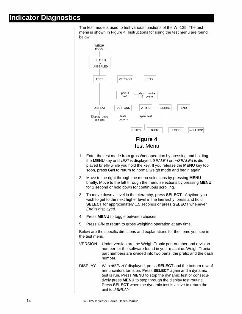
Indicator DiagnosticsThe test mode is used to test various functions of the WI-125. The testmenu is shown in Figure 4. Instructions for using the test menu are foundbelow.
Figure 4Test Menu
1. Enter the test mode from gross/net operation by pressing and holdingthe MENU key until tESt is displayed. SEALEd or unSEALEd is dis-played briefly while you hold the key. If you release the MENU key toosoon, press G/N to return to normal weigh mode and begin again.
2. Move to the right through the menu selections by pressing MENUbriefly. Move to the left through the menu selections by pressing MENUfor 1 second or hold down for continuous scrolling.
3. To move down a level in the hierarchy, press SELECT. Anytime youwish to get to the next higher level in the hierarchy, press and holdSELECT for approximately 1.5 seconds or press SELECT wheneverEnd is displayed.
4. Press MENU to toggle between choices.
5. Press G/N to return to gross weighing operation at any time.
Below are the specific directions and explanations for the items you see inthe test menu.
VERSION Under version are the Weigh-Tronix part number and revisionnumber for the software found in your machine. Weigh-Tronixpart numbers are divided into two parts: the prefix and the dashnumber.
DISPLAY With diSPLAY displayed, press SELECT and the bottom row ofannunciators turns on. Press SELECT again and a dynamictest is run. Press MENU to stop the dynamic test or consecu-tively press MENU to step through the display test routine.Press SELECT when the dynamic test is active to return theunit to diSPLAY.

15WI-125 Indicator Series User's Manual
Wiring Connections
WI-125 Super Saverand Full FeaturePin Assignments(optional NEMA 4X)
WI-125 NEMA 4XPin Assignments
BUTTONS With buttonS displayed, press SELECT and an underscore willappear on the screen. Press any key except MENU to checkfor proper key functioning. After testing the buttons, pressMENU to return to the display.
A to D Displays the analog to digital counts. The span is normally20000 counts per millivolt per volt. With a calibrator at zeromillivolts per volt, the displayed value should be between -200and +200.
SERIAL Tells you if the serial output is ready or busy. A jumper connect-ing pins DTR to CTS of the serial port will cause buSY to bedisplayed. Pressing the MENU key puts no LOOP on thedisplay. With pins XMITT to RECV connected, LOOP is dis-played. With them disconnected, no LOOP is displayed.
The following pin-outs refer to the connector on the back of the WI-125Super Saver and Full Feature. The colors mentioned in the table beloware Weigh-Tronix Weigh Bar colors only!
Following are instructions for connecting the weight sensors and the RS-232cables to the terminal boards on the WI-125 NEMA 4X Indicator. Refer toFigure 5 on the next page.
To access the terminal boards:
1. Remove power from the scale.
2. Remove display enclosure from the mounting bracket by removing thefour 1/2" 10-32 capscrews securing the display case to the mountingbracket.
3. Remove the two 3/8" 10-32 capscrews securing the enclosure bracketsand carefully pull the enclosure halves apart.
You may now access the two terminal blocks (TB1 and TB2) which arelocated in the back half of the enclosure on the left hand side. See Figure 6on the next page.
To reassemble the WI-125, reverse the steps listed above, making sure toreinsert the shorter capscrews in the middle position of the enclosurebracket.
B Green (+) Excitation
D Black (-) Excitation
F Yellow (+) Sense
E Blue (-) Sense
C White (+) Signal
A Red (-) Signal
G Wht/Orn Shield

16 WI-125 Indicator Series User's Manual
Figure 5Internal connections
On systems using remotesense (7 wires), store jumperon a single pin of P7 and P8.On systems not using remotesense (5 wires), jumper P7-1 toP7-2 and P8-1 to P8-2 withjumper.
Signal Cable Connections
Terminal Board Description WT Wire Color
TB201 +Excitation Green
TB2-2 +Sense Yellow
TB2-3 +Output White
TB2-4 Shield (Gnd) White/Orange
TB2-5 -Output Red
TB2-6 -Sense Blue
TB2-7 -Excitation Black
17WI-125 Indicator Series User's Manual
WI-125 Super Saverand Full Feature
WI-125 NEMA 4X
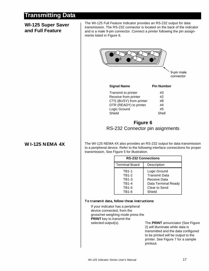
Transmitting DataThe WI-125 Full Feature Indicator provides an RS-232 output for datatransmission. The RS-232 connector is located on the back of the indicatorand is a male 9-pin connector. Connect a printer following the pin assign-ments listed in Figure 6.
Signal Name Pin Number
Transmit to printer #3Receive from printer #2CTS (BUSY) from printer #8DTR (READY) to printer #4Logic Ground #5Shield Shell
Figure 6RS-232 Connector pin asignments
The WI-125 NEMA 4X also provides an RS-232 output for data transmissionto a peripheral device. Refer to the following interface connections for propertransmission. See Figure 5 for illustration.
RS-232 Connections
Terminal Board Description
TB1-1 Logic GroundTB1-2 Transmit DataTB1-3 Receive DataTB1-4 Data Terminal ReadyTB1-5 Clear to SendTB1-6 Shield
To transmit data, follow these instructions:
If your indicator has a peripheraldevice connected, from thegross/net weighing mode press thePRINT key to transmit theselected output(s). The PRINT annunciator (See Figure
2) will illuminate while data istransmitted and the data configuredto be printed will be output to theprinter. See Figure 7 for a sampleprintout.
18 WI-125 Indicator Series User's Manual
Figure 6: Sample WI-125 Printout
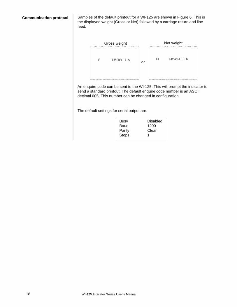
Communication protocol Samples of the default printout for a WI-125 are shown in Figure 6. This isthe displayed weight (Gross or Net) followed by a carriage return and linefeed.
An enquire code can be sent to the WI-125. This will prompt the indicator tosend a standard printout. The default enquire code number is an ASCIIdecimal 005. This number can be changed in configuration.
The default settings for serial output are:
Busy DisabledBaud 1200Parity ClearStops 1

19WI-125 Indicator Series User's Manual
Declaration of Conformance to SMA StandardYear of Declaration 2002Production Meets Type
® *
We the manufacturer of
Model Type Certificate and Number Issued by
WI-125 Electronic Indicator NTEP CC 92-167A4 NCWM
Declare in our responsibility the conformance of the above listed models and types to thementioned certificates and the requirements of the SMA standard.
This declaration becomes valid when the SMA Conformance Logo, having our name or trade-mark is applied to the device or its accompanying documentation.
* SMA PRODUCTION MEETS TYPE DEVICE MANUFACTURER Conformance Logo and Design are a registeredtrademark of the Scale Manufacturers Association

Weigh Bar® is a registered trademark of Weigh-Tronix Inc.
Avery Weigh-Tronix Canada, ULC217 Brunswick BoulevardPointe Claire, QC H9R 4R7 CanadaTelephone: 514-695-0380Toll free: 800-561-9461Facsimile: 514-695-6820www.weigh-tronix.ca
Avery Weigh-Tronix1000 Armstrong Dr.Fairmont, MN 56031 USATelephone: 507-238-4461Facsimile: 507-238-4195e-mail: [email protected]