Whole House Heat Recovery Unit for domestic and … LCD Ins 070817.pdf · rect connection of the...
5
EVO250DC Whole House Heat Recovery Unit for domestic and commercial use with Low Energy DC Motors Optional - Remote LCD Installation, Operating and Maintenance Instructions
Transcript of Whole House Heat Recovery Unit for domestic and … LCD Ins 070817.pdf · rect connection of the...

EVO250DC
Whole House Heat Recovery Unit
for domestic and commercial use
with Low Energy DC Motors
Optional - Remote LCD
Installation, Operating and Maintenance
Instructions
Page 2
"EVO250DC" - WHOLE HOUSE HEAT RECOVERY UNITINSTALLATION AND OpERATINg INSTRUCTIONS
Safety Notice
It is important to read this Instruction Manual carefully before installing or using the product. Following
these instructions will ensure that your ventilation system is installed, commissioned and used properly and
continues to operate effectively. Vectaire will not be held responsible and will not accept liability for any dam-
age caused to persons or property through failure to follow the guidance provided in this manual. It should
always be available with the product for easy reference.
EVO250DC: for dwellings up to 150m2m maximum capacity 320m3/hr
-general Information
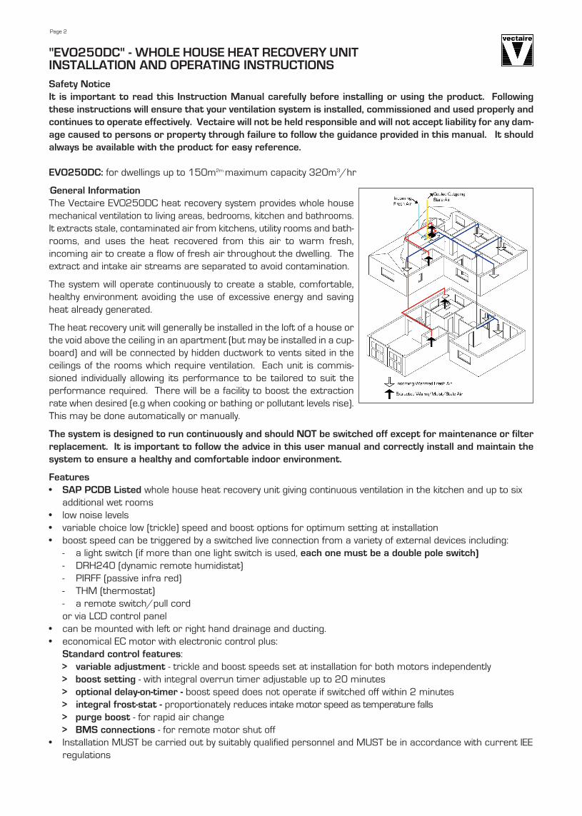
The Vectaire EVO250DC heat recovery system provides whole house
mechanical ventilation to living areas, bedrooms, kitchen and bathrooms.
It extracts stale, contaminated air from kitchens, utility rooms and bath-
rooms, and uses the heat recovered from this air to warm fresh,
incoming air to create a flow of fresh air throughout the dwelling. The
extract and intake air streams are separated to avoid contamination.
The system will operate continuously to create a stable, comfortable,
healthy environment avoiding the use of excessive energy and saving
heat already generated.
The heat recovery unit will generally be installed in the loft of a house or
the void above the ceiling in an apartment (but may be installed in a cup-
board) and will be connected by hidden ductwork to vents sited in the
ceilings of the rooms which require ventilation. Each unit is commis-
sioned individually allowing its performance to be tailored to suit the
performance required. There will be a facility to boost the extraction
rate when desired (e.g when cooking or bathing or pollutant levels rise).
This may be done automatically or manually.
The system is designed to run continuously and should NOT be switched off except for maintenance or filter
replacement. It is important to follow the advice in this user manual and correctly install and maintain the
system to ensure a healthy and comfortable indoor environment.
Features
• SAp pCDB Listed whole house heat recovery unit giving continuous ventilation in the kitchen and up to six
additional wet rooms
• low noise levels
• variable choice low (trickle) speed and boost options for optimum setting at installation
• boost speed can be triggered by a switched live connection from a variety of external devices including:
- a light switch (if more than one light switch is used, each one must be a double pole switch)
- DRH240 (dynamic remote humidistat)
- PIRFF (passive infra red)
- THM (thermostat)
- a remote switch/pull cord
or via LCD control panel
• can be mounted with left or right hand drainage and ducting.
• economical EC motor with electronic control plus:
Standard control features:
> variable adjustment - trickle and boost speeds set at installation for both motors independently
> boost setting - with integral overrun timer adjustable up to 20 minutes
> optional delay-on-timer - boost speed does not operate if switched off within 2 minutes
> integral frost-stat - proportionately reduces intake motor speed as temperature falls
> purge boost - for rapid air change
> BMS connections - for remote motor shut off
• Installation MUST be carried out by suitably qualified personnel and MUST be in accordance with current IEE
regulations

IT IS IMpORTANT THESE INSTRUCTIONS AREREAD FULLY BEFORE INSTALLATION• This product should not be used for any purpose
other than that for which it was designed and as shown in this leaflet.
• All packaging should be removed and the unit checked for damage in transit. If there is any damage, please contact your supplier.
• The EVO250DC will generally be fitted into a loft orceiling void. In order to comply with Construction(Design & Management) Regulations, sufficientaccess for safe maintenance (recommended onan annual basis), or removal following installa-tion, MUST be provided for this product. We recommend that a clearance of at least 150mmis available on each side of the cabinet to allow access to the motors. See dimensions diagram.
• Fire Dampers must be fitted to duct work at appropriate locations in accordance with Building Regulations
• Flue gases from fuel-burning equipment must not be drawn into a living area. If any room from which airis extracted contains a fuel burning appliance, such as a central heating boiler, then its flue must be of the sealed or balanced flue type, or allowance must be made for an adequate supply of air into the room.
• The unit must NOT be installed:- where there is excessive oil or grease- where there are hazardous gases, liquids or vapours that are flammable or corrosive- in ambient temperatures above 50ºC or lower than 5ºC (-28ºC using pre-heater)- in humidity levels above 90% or in a wet environment
• Where possible the unit should NOT be installed directly above a bedroom or living room. • The condensation drain MUST be fitted and if insulated, use the equivalent of at least 25mm of insulating
material with a thermal conductivity of 0.04 W/(mK)• Care should be taken to ensure that ducting is free from blockages before switching on the unit as this may
invalidate your guarantee• External grilles should be located a minimum of 600mm from any flue outlet in accordance with all
Regulations• The unit must be connected to a 230v-240v, 50Hz single phase electrical supply. • A triple pole isolation switch with contact separation of at least 3mm must be used to connect the appliance
to the fixed wiring when using the Switched Live.• The product should only be connected to the mains electricity supply or electrical outlet if:
- your electrical voltage and frequency correspond to those shown on the rating label.- the capacity of your electricity supply is sufficiently powerful to operate the product at its
maximum power.• If one of the spigots is not connected to ducting a safety grille MUST be fitted to that spigot, so that it is
impossible for any moving part to be touched.
Installation of the appliance MUST be carried out by a qualified and suitably competent person and should be carried out in clean, dry conditions where dust and humidity are at minimal levels. The unit is not suitable for installation to the exterior of the dwelling.
Transportation, packaging and storage prior to installation
• Care should be taken when transporting the unit. Dropping or knocking will damage the inner workings
of the unit.
• The unit should always be stored in a clean, dry environment.
• Remove all packaging before installation.
pre-inspection
• Inspect the unit and electrical supply cord for any damage (damage must be repaired by a suitably
qualified and competent person.)
Page 3

Duct and Duct Connections (refer to design drawing)• 4 x 204mmx 60mm spigots are provided for the connection of ducting. These are clearly marked for cor-
rect connection of the supply and exhaust ducts. • Where ducting is installed in an unheated space, all of the ducts should be insulated. Where ducting is in
stalled in a heated space, only the cold ducts should be insulated. i.e. the supply duct from outside and the ex-tract duct from the unit to the outside.
• The duct layout must be designed to suit the requirements of the ventilation/recovery system and building lay-out. If the ducting passes through a fire wall/barrier, suitable fire dampers must be installed.
• Where rigid duct is used, it should be installed using the least number of fittings to minimise air flow resist-ance. Where possible, final connection to the grilles and unit should be made with a flexible connection.
• Where flexible ducts are used, ensure that:- duct runs are kept as short as possible- the duct is stretched so that it is smooth and straight- where bends are necessary, they have large radii (ie avoid sharp bends)- the duct is not crushed if in a restricted area
Condensation(The unit may sometimes produce condensation which must be drained away. A 15mm dia pipe connection isprovided on this unit).• A 15mm dia pipe must be fitted to the pipe connection. If any part of the condensate drain is in an
unheated space it MUST be insulated with the equivalent of at least 25mm of insulating material with a thermal conductivity of 0.04 W/(mK).
• The pipe must drain into the normal household drainage system. • The drain must incorporate a wet or dry trap to prevent air penetration.• The unit must be tilted towards the side carrying the condensation exit point. It should be installed
horizontally with a 3º tilt towards the condensation drain used (equivalent of raising the opposite end by approximately 25mm).
• The drainage pipe must have a continuous fall from the unit to the drainage collection point.
Electrical ConnectionWARNINg: these appliances must be earthed and all wiring must conform to current IEE Regulations and all appli-cable standards and Building Regulations.• The unit is suitable for 230V, 50Hz Single phase supply.• The unit is supplied with:
- A mains rated 4 core flexible cord (black, brown, grey and green/yellow) and 2 core 0-10v cables for purge switching, or an external connector box.
Cables for any other external device will be provided and labelled on request• A triple pole isolation switch with contact separation of at least 3mm must be used to connect the appliance to the
fixed wiring when using the Switched Live. • Boost controls must not be located within 1 metre of a cooker or where they may be affected by excessive heat or
moisture.• Boost and other external controls should be clearly identified and conveniently located.• The boost facility can be activated by a switched live connection (in addition to the permanent supply live). The
switched live can be operated by a variety of external devices, including:- PIRFF (passive infra red)*- DRH240 (dynamic remote humidistat)*- THM (thermostat)*- a light switch (if more than one light switch is used, each one must be a double pole switch)- a remote switch/pull cord or via LCD control(*PIRFF, DRH240 and THM may have integral over-run timer which controls the length of time that the fan will continue to operate at its boost speed after the boost has been switched off.)
Page 4

Page 5
Commissioning
1. The commissioning must only be carried
out by a suitably qualified person.
2. Prior to starting the commissioning pro-
cedure, ensure that the ductwork con-
nections and airflow directions match
one of the options 1 or 2, shown on page
4. Check that the drain connection is on
the correct side.
3. Before making any adjustments, ensure
that the air valves or grilles are fully open.
4. please see separate "LCD Control panel
Commissioning Instructions" for details
on commissioning and user operations..
WARNINg : With the control board panel
removed, 230 volt live connections are
accessible.
Cleaning and Maintenance
WARNINg: The unit uses a 230V supply and contains rotating mechanical parts.
• Before carrying out any maintenance or cleaning operations the mains electrical supply MUST be dis-
connected.
The air filters and heat exchanger of the Vectaire EVO250DC should be cleaned regularly by a
suitably qualified person (the frequency of cleaning will vary depending on the installation environment). Filters should
be replaced after a maximum of 3 cleaning cycles.
Filters:
• Remove the filter covers on the front panel.
• Slide out the filters by pulling out the tabs
• Clean the filters carefully using a vacuum cleaner, replace in the slots and refit the filter covers
Heat Exchanger:
• Firstly remove filters as described above
• Remove the screws securing the front panel and carefully lift off. Using the plastic strap fitted, carefully pull
out the heat exchanger
• Caution: if this is done during cold weather, the heat exchanger may contain water. It is advisable to have a
plastic bowl available to avoid spillage.
• Lightly clean the faces of the heat exchanger with a vacuum cleaner. Replace the heat exchanger carefully,
by sliding the assembly back into the cabinet.
• Replace the front cover by hooking the top edge into the slots in the cabinet and secure in place using the
screws.
• Finally, replace the filters as above.
Never use water or any other fluids to clean the heat exchanger.
• Return the heat exchanger and filters to their original position.
• Replace the front cover and ensure it is securely located at the top before tightening all screws.
• Power to the unit can now be restored.
Filter Replacement
Filters should be replaced annually or after a maximum of 3 cleaning cycles.
Replacement filters are available from Vectaire - call us on +44 (0) 1494 522333 or via [email protected]
Vectaire Ltd, Lincoln Road, Cressex Business Park, High Wycombe, Buckinghamshire, HP12 3RH
Tel: +44 (0)1494 522333. Fax: +44 (0)1494 522337. Email: [email protected]
EVO250DC LCD 070817 E & O.E