White paper XDi-net/CANopen reference manual
75
DEIF A/S XDi-net/CANopen reference manual 4189350066A Table of contents White paper DEIF A/S, Frisenborgvej 33 Tel.: +45 9614 9614, Fax: +45 9614 9615 DK-7800 Skive, Denmark E-mail: [email protected], URL: www.deif.com
Transcript of White paper XDi-net/CANopen reference manual

DEI
F A
/S
XDi-net/CANopen reference manual 4189350066A
Table of contents
White paper
DEIF A/S, Frisenborgvej 33 Tel.: +45 9614 9614, Fax: +45 9614 9615 DK-7800 Skive, Denmark E-mail: [email protected], URL: www.deif.com

XDi series XDi-net/CANopen reference manual
DEIF A/S Page 2 of 75
Introduction .................................................................................................................................. 5 EDS FILE FOR THE XDI CANOPEN INDICATOR ............................................................................... 5 USE OF CAN IN XDI INDICATORS ................................................................................................... 6 CAN NODE-ID ............................................................................................................................. 6
Node-ID shift ......................................................................................................................................... 7 Node-ID shift via CANopen ................................................................................................................... 7
GENERAL CAN BUS SETUP ........................................................................................................... 7 CAN BUS MODES .......................................................................................................................... 8
XDi-net dual communication (mode 2) .................................................................................................. 8 XDI-net redundant communication (mode 3) ........................................................................................ 8
SUPPORTED BIT RATES ON CAN.................................................................................................... 9 Change of bit rate via CANopen ........................................................................................................... 9
CAN PROTOCOLS AVAILABLE IN XDI .............................................................................................. 9 CANopen mode .................................................................................................................................... 9 XDi-net mode ........................................................................................................................................ 9 XDI-net restrictions on CANopen ........................................................................................................ 10 Reserved CAN PDOs – COB-IDs ....................................................................................................... 10
RESTRICTED NODE-ID - SERVICE UNIT ......................................................................................... 10 XDi-net conflicts .................................................................................................................................. 10
SELF-STARTING DEVICE .............................................................................................................. 11 AUTOMATIC START COMMAND ..................................................................................................... 11 HEARTBEAT................................................................................................................................ 11
In CANopen mode .............................................................................................................................. 11 CAN data source for a virtual indicator ................................................................................... 12
OBJECT INDEX FOR VARIABLE DATA ............................................................................................. 12 Variable data format in object index .................................................................................................... 12 Indication of invalid variable data ........................................................................................................ 13 Data lost - variable data timeout ......................................................................................................... 13 Variable data type “Flag” .................................................................................................................... 13
HOW TO GET DATA INTO THE OBJECT INDEX TABLE ....................................................................... 14 XDI-NET DATA TRANSFER ............................................................................................................ 15 DATA DISTRIBUTION USING DAM-MPDO ..................................................................................... 15 TPDO OR RPDO AS DATA CARRIER ............................................................................................ 15
PDO converter .................................................................................................................................... 15 TPDO and RPDO used for data broadcast ......................................................................................... 16
EXTENSION MODULE DATA SHARING ............................................................................................ 17 OVERVIEW OF CAN DATA SOURCES ............................................................................................ 17
Distribution of XDi data ............................................................................................................. 18 DATA DISTRIBUTION USING XDI-NET BROADCAST ......................................................................... 18
Transmitting XDi-net data ................................................................................................................... 18 Receiving XDi-net data ....................................................................................................................... 18
CUSTOMER SYSTEMS’ USE OF XDI-NET BROADCAST ..................................................................... 18 CAN frame format for XDi-net broadcast ............................................................................................ 18
EXAMPLE 1: TRANSMITTING PROPELLER RPM USING XDI-NET ...................................................... 19 EXAMPLE 2: WRITING TO A CRITICAL BAND USING XDI-NET PROTOCOL ........................................... 20
Object index addresses of critical bands ............................................................................................ 20 Setup/activation of critical bands ........................................................................................................ 20
Product parameter setup via CAN ........................................................................................... 21 MANUFACTURER-SPECIFIC OBJECT INDEX .................................................................................... 21 0X2000 PARAMETERS ................................................................................................................. 22 0X4000 PARAMETERS ................................................................................................................. 22 SDO WRITE PROTECTION ............................................................................................................ 22
SDO write protection index ................................................................................................................. 22 SDO WRITE UNLOCK PROCEDURE ............................................................................................... 22
Automated XDi start-up configuration via CANopen ............................................................. 26
XDi series XDi-net/CANopen reference manual
DEIF A/S Page 3 of 75
AUTOMATED CONFIGURATION OF A SERVICE DEVICE ..................................................................... 26 FULLY AUTOMATED SETUP AFTER REPLACEMENT OF A FAULTY XDI................................................ 26 PROCEDURE FOR AUTOMATED INDICATOR SETUP ......................................................................... 26 EXAMPLE - AUTOMATED CONFIGURATION VIA CAN ....................................................................... 30
Emergency message – XDi is not set up ............................................................................................ 30 Changing headline on a virtual indicator via CAN ................................................................. 34
CHANGING HEADLINES ON A VIRTUAL INDICATOR .......................................................................... 34 Select new headline from pre-defined text list .................................................................................... 34 Write new custom headline text to the XDi and select it ..................................................................... 35 Make custom headline visible in the XDi menu................................................................................... 35 Select custom headline to be visible on the virtual indicator ............................................................... 35
CHANGE LABELS OR UNITS ON A VIRTUAL INDICATOR .................................................................... 35 Rotate the display presentation 180o via CAN ........................................................................ 36 Error and fault messages .......................................................................................................... 36
WARNINGS AND ALERTS .............................................................................................................. 36 Appendix 1 - CANopen standard object dictionary ............................................................... 38
OBJECT 0X1000 DEVICE TYPE (MANDATORY) ............................................................................... 38 OBJECT 0X1001 ERROR REGISTER .............................................................................................. 38 OBJECT 0X1008 MANUFACTURER DEVICE NAME (USED - OPTIONAL) ............................................ 39 OBJECT 0X100A MANUFACTURE SOFTWARE VERSION (USED - OPTIONAL) ................................... 39 OBJECT 0X100C GUARD TIME (CONDITIONAL) .............................................................................. 40 OBJECT 0X100D LIFETIME FACTOR (CONDITIONAL) ...................................................................... 40 OBJECT 0X1010 STORE PARAMETERS (USED - OPTIONAL) .......................................................... 40 OBJECT 0X1011 RESTORE DEFAULT PARAMETERS (USED - OPTIONAL) ........................................ 42 OBJECT 0X1014 COB-ID EMERGENCY MESSAGE......................................................................... 43 OBJECT 0X1016 CONSUMER HEARTBEAT TIME (USED - OPTIONAL) .............................................. 43 OBJECT 0X1017 PRODUCER HEARTBEAT TIME (USED - CONDITIONAL) ......................................... 43 OBJECT 0X1018 IDENTITY OBJECT (MANDATORY) ......................................................................... 44
Vendor ID ........................................................................................................................................... 44 Product code....................................................................................................................................... 45 XDi-net revision number ..................................................................................................................... 46 Serial number ..................................................................................................................................... 46
Appendix 2 - data directory - XDi object index 0x2000-2FFF ................................................ 47 OBJECT 0X2000 SELF-STARTING DEVICE (OPTIONAL) ................................................................... 47
Appendix 3 - XDi object index 0x3000-3FFF ........................................................................... 48 DATA TYPE GROUPING/DATA TYPE INSTANCE ................................................................................ 48
Location of data type at a given instance in the data object index table ............................................. 48 Pre-defined variable data indexes ...................................................................................................... 48
APPENDIX 3.1 - GENERAL RULES FOR XDI VARIABLE DATA AND PARAMETERS................................. 50 Indicator source data via CAN bus ..................................................................................................... 50
APPENDIX 3.2 - INPUT DATA STRUCTURE IN THE XDI DATA DIRECTORY .......................................... 51 Object index structure for all variable data types ................................................................................ 51 Object index structure for dimmer groups ........................................................................................... 55
Appendix 4 - index 0x4000-4FFF product parameters ........................................................... 57 OBJECT INDEX LIST 0X4000-0X40FF .......................................................................................... 58 XDI DIRECTORY 0X4100-0X42FF DEFINITIONS (VIRTUAL INDICATOR SETUP) ................................. 63
Definition of text lists for virtual indicators 0x4100 to 0x414F ............................................................. 63 Appendix 5 - XDi error and fault indication ............................................................................. 66
XDI-CAN BUS ERROR DETECTION IN MODE .................................................................................. 66 ERROR MESSAGING ON CAN....................................................................................................... 66 CAN FAILURE CAUSE AND TYPE ................................................................................................... 66 SUPPLY VOLTAGE FAILURES ........................................................................................................ 67

XDi series XDi-net/CANopen reference manual
DEIF A/S Page 4 of 75
Appendix 6 - MPDO parameter settings .................................................................................. 68 General CANopen header parameter settings .................................................................................... 68 SAM-MPDO communication parameter settings (index 0x1400-0x1403) ........................................... 68 SAM-MPDO mapping parameter settings (index 0x1600-0x17FF) ..................................................... 69 DAM-MPDO settings .......................................................................................................................... 69 DAM-MPDO communication parameter settings (index 0x1400-0x1403) ........................................... 69 DAM-MPDO mapping parameter settings (index 0x1600-0x17FF) ..................................................... 70
Appendix 7 - explanation of the “Obj. index table” fields ..................................................... 71 Index/sub-index .................................................................................................................................. 71 Object description ............................................................................................................................... 71 Obj. code – data type .......................................................................................................................... 71 Acc. (access) ...................................................................................................................................... 71 Default value ....................................................................................................................................... 71 Cat. M/O - object category in XDi-net ................................................................................................. 71 Default COB-ID/communication object ............................................................................................... 71
Appendix 8 - EDS file description ............................................................................................ 72 INTRODUCTION ........................................................................................................................... 72 EDS FILE - OBJECT INDEX CONTENT ............................................................................................ 72
CANopen defined object indexes, 0x1000 group ................................................................................ 72 MANUFACTURER-SPECIFIC CAN INDEXES, 0X2000 TO 0X5FFF .................................................... 74
Variable input data, 0x3000 group ...................................................................................................... 74 Product setup data 0x4000 group ....................................................................................................... 74
This document is subject to change and update without notification.
XDi series XDi-net/CANopen reference manual
DEIF A/S Page 5 of 75
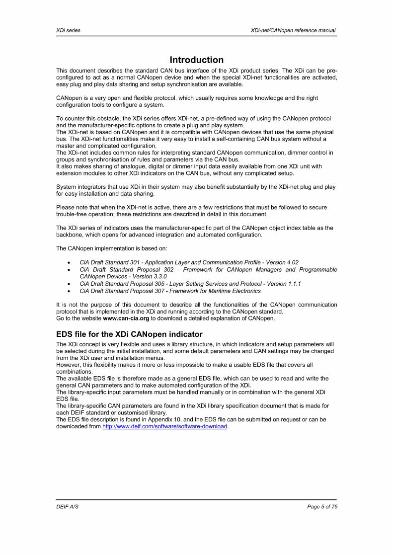
Introduction This document describes the standard CAN bus interface of the XDi product series. The XDi can be pre-configured to act as a normal CANopen device and when the special XDi-net functionalities are activated, easy plug and play data sharing and setup synchronisation are available. CANopen is a very open and flexible protocol, which usually requires some knowledge and the right configuration tools to configure a system. To counter this obstacle, the XDi series offers XDi-net, a pre-defined way of using the CANopen protocol and the manufacturer-specific options to create a plug and play system. The XDi-net is based on CANopen and it is compatible with CANopen devices that use the same physical bus. The XDi-net functionalities make it very easy to install a self-containing CAN bus system without a master and complicated configuration. The XDi-net includes common rules for interpreting standard CANopen communication, dimmer control in groups and synchronisation of rules and parameters via the CAN bus. It also makes sharing of analogue, digital or dimmer input data easily available from one XDi unit with extension modules to other XDi indicators on the CAN bus, without any complicated setup. System integrators that use XDi in their system may also benefit substantially by the XDi-net plug and play for easy installation and data sharing. Please note that when the XDi-net is active, there are a few restrictions that must be followed to secure trouble-free operation; these restrictions are described in detail in this document. The XDi series of indicators uses the manufacturer-specific part of the CANopen object index table as the backbone, which opens for advanced integration and automated configuration. The CANopen implementation is based on:
CiA Draft Standard 301 - Application Layer and Communication Profile - Version 4.02 CiA Draft Standard Proposal 302 - Framework for CANopen Managers and Programmable
CANopen Devices - Version 3.3.0 CiA Draft Standard Proposal 305 - Layer Setting Services and Protocol - Version 1.1.1 CiA Draft Standard Proposal 307 - Framework for Maritime Electronics
It is not the purpose of this document to describe all the functionalities of the CANopen communication protocol that is implemented in the XDi and running according to the CANopen standard. Go to the website www.can-cia.org to download a detailed explanation of CANopen.
EDS file for the XDi CANopen indicator The XDi concept is very flexible and uses a library structure, in which indicators and setup parameters will be selected during the initial installation, and some default parameters and CAN settings may be changed from the XDi user and installation menus. However, this flexibility makes it more or less impossible to make a usable EDS file that covers all combinations. The available EDS file is therefore made as a general EDS file, which can be used to read and write the general CAN parameters and to make automated configuration of the XDi. The library-specific input parameters must be handled manually or in combination with the general XDi EDS file. The library-specific CAN parameters are found in the XDi library specification document that is made for each DEIF standard or customised library. The EDS file description is found in Appendix 10, and the EDS file can be submitted on request or can be downloaded from http://www.deif.com/software/software-download.

XDi series XDi-net/CANopen reference manual
DEIF A/S Page 6 of 75
Use of CAN in XDi indicators The XDi series is designed for integration in a large variety of systems that utilise the CANopen protocol in many different ways, which this very open standard renders possible. Therefore, the goal has been to make the XDi CAN interface quite flexible and able to adapt to specific customer needs. The virtual indicator with scale and one or more pointers, bar graphs and digital readouts are defined in the “virtual indicator file” (VI). Input and configuration parameters for each virtual indicator (VI) are defined in a virtual indicator setup profile (VI setup profile, or VS). It is possible to specify up to 50 different VI setup profiles for each virtual indicator. This is quite useful if indicator inputs and default parameters must be set differently in different system configurations in which the indicator is used. The same applies to product-related parameters, like CAN bus and dimmer group settings; they are stored in a product profile (PP), and they are independent of the virtual indicator that is presented on the XDi display. There may also be up to 50 different product profiles in a library. XDi must always contain a virtual indicator library to be able to operate.
XDi library structure. The first time an XDi is started after the installation, a setup wizard will automatically appear and guide you through the selection of: Node-ID, product profile (PP), virtual indicator (VI) and VI setup profile (VS). In many cases, these five easy steps complete the installation. Virtual indicators, VI setups and product profiles are all identified by numbers, which makes it possible to make an automated setup via the CAN bus as soon as the Node-ID is assigned.
CAN Node-ID The CAN Node-ID is the unique identifier for a device in the XDi-net system, and it is fixed after installation/commissioning. The library contains a default Node-ID that will be suggested as the default selection in the start-up wizard. The Node-ID selection is the first operation that is performed in the start-up wizard. If heartbeat is active, the XDi will monitor this from all nodes on the CAN bus, and if there is a Node-ID conflict, the Node-ID will be greyed out in the wizard menu and cannot be selected. Recommendation: write the CAN Node-ID on the small white label behind the front frame of the XDi unit. The XDi unit will not be active on the CAN bus until the Node-ID is selected.
Virtual indicator 1 VI-setup 3 Product Profile 1
Virtual indicator 2
Virtual indicator N
VI-setup 2 VI-setup 1
VI-setup 4 VI-setup 3
VI-setup 2VI-setup 1
VI-setup 2 VI-setup 1
Product Profile 2
Product Profile X. . .
.
.
.

XDi series XDi-net/CANopen reference manual
DEIF A/S Page 7 of 75
Node-ID shift In normal CANopen installations, the Node-ID is very important for data routing and system configuration, so you should be very careful when you change the Node-ID in a running installation. If the XDi-net broadcast protocol is used, the Node-ID is not critical for the normal operation, but if your CAN system uses automated setup via CAN, you should be equally careful when you change the Node-ID. It is possible to re-open the setup wizard to change the Node-ID. If it is changed because the unit is to be used as a service unit elsewhere in the system, it is recommended to make a master reset instead, this will restore the factory settings of the XDi.
Node-ID shift via CANopen A CAN controller is able to shift the Node-ID by using the CANopen LLS setup procedure (standard CANopen procedure, not described in this document).
General CAN bus setup XDi 96, 144 and 192 all have two independent and galvanically insulated CAN ports. The general CAN bus setup for both CAN ports is pre-defined in the product profile. Settings can be changed from the XDi installation menu.
CAN function XDi-net ON XDi-net OFF Note CAN bus mode: Single
2 x single, redundant
Single 2 x single, redundant
May even be OFF, if the CAN bus is not used.
Bit rate CAN1 (kbps): 20, 50, 125, 250, (500, 1000)
20, 50, 125, 250, (500, 1000)
Bit rate CAN2 (kbps): 20, 50, 125, 250, (500, 1000)
20, 50, 125, 250, (500, 1000)
XDi-net functions: ON OFF XDi-net functions are disabled.
XDi-net variable data on: CAN1, CAN2, CAN1&2 (not OFF)
OFF Menu greyed out!
Broadcast of XDi data to other XDi units, dimmer values and variable data from analogue or digital inputs.
Send XDi-net setup synch. data on:
CAN1, CAN2, CAN1&2 (not OFF)
OFF Menu greyed out!
The XDi will not be able to synchronise parameter changes if this function is OFF.
Send CAN heartbeat on: CAN1, CAN2, CAN1&2 (not OFF)
NO, CAN1, CAN2, CAN1&2
Must be ON when running XDi-net and will be permanently ON if redundant CAN is selected.
Auto start XDi on the CAN bus:
YES YES/NO Must be ON when running XDi-net.
Send CAN start command on CAN bus:
NO, CAN1, CAN2, CAN1&2
NO, CAN1, CAN2, CAN1&2
Used to activate a CAN sensor without built-in auto-start
DAM-MPDO to be used: NONE or RPDO2-4
NONE or RPDO1-4
If MPDO data transfer is used, an RPDO must be selected.

XDi series XDi-net/CANopen reference manual
DEIF A/S Page 8 of 75
CAN bus modes Both CANopen and XDi-net can be set up to one of the following bus modes:
Mode 1: “Single CAN bus”, only CAN1 is active. Mode 2: for “two independent CAN buses” the settings are normally the same for both buses, but they may be set up differently for bus 1 and bus 2. However, the Node-ID will always be the same on both buses! Mode 3: redundant CAN bus mode may be used in systems controlled by a CAN master (NMT), it should not be used in systems without a master.
XDi-net dual communication (mode 2)
Service CAN1 CAN2 Note PDO TX/RX A TX/RX B MPDO TX/RX A TX/RX B XDi-net TX/RX A TX/RX B XDi-net broadcast (SAM-MPDO) SDO TX/RX A TX/RX B EMCY TX/RX A TX/RX B Sync TX/RX A TX B Not used by XDi Time TX/RX A TX B Not used by XDi NMT TX/RX A TX/RX B Error control TX/RX A TX/RX B
A and B indicate whether the same or different services are running on the two channels. A on both = same services (data) running on both buses, A and B = different services (data) on the two busss. In mode 2 it is possible to run two electrically independent CAN buses as one bus. Input and setup data on both channels will be handled equally. Input data for a virtual indicator can come from one of the two or from both CAN buses – this is defined in the VI setup profile.
XDI-net redundant communication (mode 3)
Service
CAN1 Primary (Default)
CAN2 Secondary (Redundant)
Note
PDO TX/RX A TX/RX A MPDO TX/RX A TX/RX A XDi-net TX/RX A TX/RX A XDi-net broadcast (SAM-MPDO) SDO TX/RX A TX/RX B EMCY TX/RX A TX/RX A Sync TX/RX A TX A Not used by XDi Time TX/RX A TX A Not used by XDi NMT TX/RX A TX/RX B Error control TX/RX A TX/RX B
A and B indicate whether the same or different services are running on the two channels. A on both = same services (data) running on both buses, A and B = different services (data) on the two buses. Variable data may be available on both channels. By default, data is accessed from the primary channel, shift to redundant data on the secondary channel is controlled via commands from the CAN master.
Mode # XDi CAN mode CAN1 CAN2 1 XDi-net/CANopen – single Active OFF 2 XDi-net/CANopen – 2 independent Active Active 3 Redundant CAN Primary active Secondary active

XDi series XDi-net/CANopen reference manual
DEIF A/S Page 9 of 75
Supported bit rates on CAN XDi supports: 20 kbit/s, 50 kbit/s, 125 kbit/s (default), 250 kbit/s, 500 kbit/s, 800 kbit/s and 1 Mbit/s. 20 kbit/s and 50 kbit/s are for long distance data transfer. Bit rate definition: Index
CiA 305 p. 10.
Bit rate CiA 301 Max. CAN
cable length
Max.recommended
total CAN cable length*)
Max. drop cable length
**)
Accumu-lated max. drop cable
length
Note
0x00 1000 kbit/s 25 m 18 m 0.5 m 4 m Not recommended 0x01 800 kbit/s 50 m 36 m 1 m 7 m Not recommended 0x02 500 kbit/s 100 m 70 m 3 m 16 m Good network layout 0x03 250 kbit/s 250 m 150 m 6 m 30 m 0x04 125 kbit/s 500 m 300 m 10 m 60 m Default 0x05 Reserved - - - - 0x06 50 kbit/s 1000 m 500 m 15 m 100 m 0x07 20 kbit/s 2500 m 1000 m 20 m 250 m 0x08 10 kbit/s - - - - Not supported by XDi 0x09 Automatic
bit rate detection
- - - Not supported by XDi
*) The recommended cable length allows for the use of connections without perfect impedance match and the use of some drop cables. **) The number of drop cables should be limited to a minimum, since it affects the network performance. Remember to include the length of any drop cable into the calculation of the total cable length.
Change of bit rate via CANopen Change of bit rate via CAN may be performed by using the LLS protocol and should be a bus wide command (note that not all devices on the bus may support LLS). Note: XDi products are not able to send a broadcast command to change the bit rate of all XDi devices on the CAN bus (NMT function).
CAN protocols available in XDi The CAN protocol is defined by the parameter settings in the product profile.
A. XDi-net if set to ON B. Pure CANopen if XDi-net is turned OFF
As a general rule, the CAN mode must be the same for all XDi devices in the CAN network.
CANopen mode When the XDi-net is disabled, the XDi will operate in standard CANopen mode and act as a slave device. It will normally be set up to act as a self-starting device, receiving CANopen data from a CANopen source without need for a CAN master (NMT) in the system.
XDi-net mode The XDi-net is built on top of CANopen to make it plug and play and still compatible with CANopen. A few restrictions must be taken into consideration for systems, in which XDi-net products are mixed with other standard CANopen products.

XDi series XDi-net/CANopen reference manual
DEIF A/S Page 10 of 75
In full XDi-net mode, the following XDi-net functions are available:
- Synchronisation of other XDi units after acknowledgement of changes like: zero set, max./min. adjustments and other parameter changes related to variable CAN input data.
- Manual adjustment of CAN data conversion, routing and synchronisation with other XDi-net units using the same CAN data source (RPDO or TPDO).
- Distribution of data from extension modules on CAN using XDi-net data broadcast (MPDO-bc) - Distribution of dimmer settings and colour shift commands using XDi-net broadcast.
The XDi-net functions may partly be selected for one or for both CAN ports: XDi-net variable data: use XDi-net for variable data sharing, transmit or receive. Send XDi-net setup synch. data: use XDi-net for synchronisation of changes.
XDI-net restrictions on CANopen When the XDi-net is activated in the product profile or via the XDi installation menu, there are some important restrictions to be taken into consideration.
Reserved CAN PDOs – COB-IDs
XDi-net setup synch. data If setup synchronisation via the XDi-net is activated, then Node-ID 127 and related RPDOs and TPDOs are restricted for XDi-net use only. The restricted COB-IDs are: TPDO 1-4: COB-ID: 0x1FF, 0x2FF, 0x3FF, 0x4FF RPDO 1-4: COB-ID: 0x27F, 0x37F, 0x47F, 0x57F All synch. data is by default sent using COB-ID: 0x27F (RPDO1/Node-ID 127) from any XDi on the network. XDi units are only listening for synchronisation data in this COB-ID.
XDi-net variable data If this function is activated, then RPDO1 for all nodes is reserved for XDi-net data distribution and it cannot not be used for any other types of communication. All COB-IDs in the range 0x200 to 27E are restricted for this use only.
Restricted Node-ID - service unit CAN Node-ID 127 is reserved as the parking address for a non-configured XDi (for example service unit). The related PDOs (COB-ID: 0x1FF, 0x27F, 0x2FF, 0x37F, 0x3FF, 0x47F, 0x4FF, 0x57F) are reserved for special XDi-net communication. Master reset of an XDi unit to “service unit mode” will park it on Node-ID 127, ready for setup either manually or via CAN. Node-ID 127 must not be selected as a normal node if XDi-net is active! Node-ID 127 must not be used as a normal CAN Node-ID for any CANopen device in a network using XDi-net functionality! As long as an XDi-net device has this “service Node-ID”, it will not send out data (PDOs or MPDOs), but it will send out heartbeat to indicate its existence, and it can be approached using SDOs, and the Node-ID can be shifted using LLS.
XDi-net conflicts If other CANopen devices in a CAN system require access to RPDO1 for non-XDi-net use or if Node-ID 127 is required for other use, then the XDi-net must be partly or entirely turned off.
XDi series XDi-net/CANopen reference manual
DEIF A/S Page 11 of 75
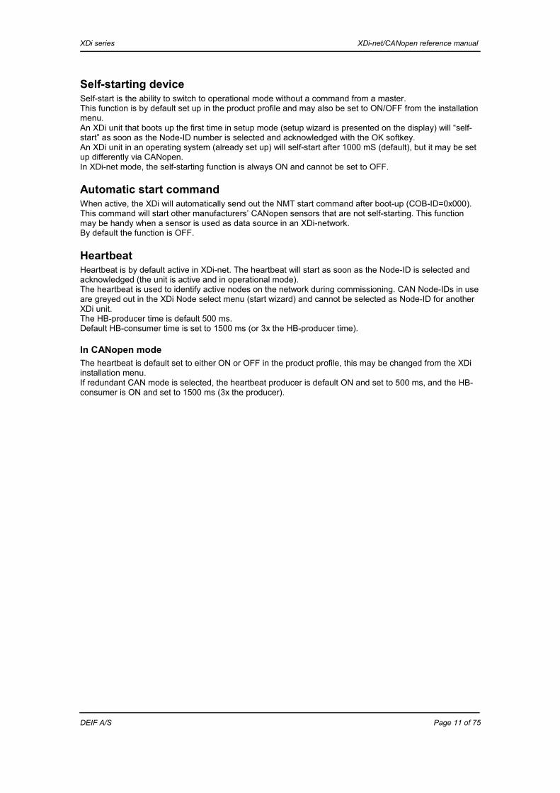
Self-starting device Self-start is the ability to switch to operational mode without a command from a master. This function is by default set up in the product profile and may also be set to ON/OFF from the installation menu. An XDi unit that boots up the first time in setup mode (setup wizard is presented on the display) will “self-start” as soon as the Node-ID number is selected and acknowledged with the OK softkey. An XDi unit in an operating system (already set up) will self-start after 1000 mS (default), but it may be set up differently via CANopen. In XDi-net mode, the self-starting function is always ON and cannot be set to OFF.
Automatic start command When active, the XDi will automatically send out the NMT start command after boot-up (COB-ID=0x000). This command will start other manufacturers’ CANopen sensors that are not self-starting. This function may be handy when a sensor is used as data source in an XDi-network. By default the function is OFF.
Heartbeat Heartbeat is by default active in XDi-net. The heartbeat will start as soon as the Node-ID is selected and acknowledged (the unit is active and in operational mode). The heartbeat is used to identify active nodes on the network during commissioning. CAN Node-IDs in use are greyed out in the XDi Node select menu (start wizard) and cannot be selected as Node-ID for another XDi unit. The HB-producer time is default 500 ms. Default HB-consumer time is set to 1500 ms (or 3x the HB-producer time).
In CANopen mode The heartbeat is default set to either ON or OFF in the product profile, this may be changed from the XDi installation menu. If redundant CAN mode is selected, the heartbeat producer is default ON and set to 500 ms, and the HB-consumer is ON and set to 1500 ms (3x the producer).

XDi series XDi-net/CANopen reference manual
DEIF A/S Page 12 of 75
CAN data source for a virtual indicator
Object index for variable data All normal data types used in marine bridge applications have pre-defined locations in the manufacturer-specific section of the object index table. Common for all types of pointers, bar graphs or digital readouts that are used in a virtual indicator, is that input data is picked from the pre-defined location in the object index table from 0x3000 to 0x3FFF. XDi index
Max. # objects
Instance
Object types Note
0x3000 – 0x3FFF
4096 Variable XDi input/output data
0x3000-0x31FF 512 Propulsion0x3000-0x300F 16 Azimuth & Rudder “-“ = bow turns to port 0x3010-0x301F 16 Rudder% “-“ = bow turns to port 0x3020-0x302F 16 Pitch angle “-“ = astern or portside 0x3030-0x303F 16 Pitch% “-“ = astern or portside 0x3040-0x307F 64 Reserved 0x3080-0x308F 16 Propeller RPM “-“ = astern or portside 0x3090-0x309F 16 Propeller RPM% “-“ = astern or portside 0x30A0-0x30AF 16 Propeller THRUST% “-“ = astern or portside 0x30B0-0x30BF 16 Propeller POWER% “-“ = astern or portside 0x30C0-0x30CF 16 Propeller LOAD %…… Reserved 0x3200-0x33FF 512 Engine data……… First part of the variable data index table. See Appendix 3 for the full table. The object index table has space for several instances of the same data type. For example, data type “Propeller RPM” is located in object index 0x3080 to 0x308F, where 0x3080 contains the data type header, and the first instance of “Propeller RPM” is located in object index 0x3081 with sub-indexes, “Propeller instance 2” in 0x3082 and so on. Pre-defined data types are scaled to an absolute data value (or defined % value) with a fixed pre-defined resolution, for example RPM with resolution 0.1 means that the data value 2000 is equal to 200.0 RPM. Scaling of all data types to an absolute value makes it possible to present the data value directly in a digital readout.
Variable data format in object index All the pre-defined data types are scaled to an absolute data value (or defined % value) with a fixed resolution, for example propeller RPM is defined with resolution 0.1, this means that if the absolute data value is 2000, it is equal to 200.0 RPM. Scaling of all data types to an absolute (or %) value makes it possible to present the data value directly in a digital readout. All standard variable data values are defined as signed 16 bit (I16), but there may be future data types using unsigned 16 bit or other formats. This is defined in the object index table. MSB LSB Byte 7 Byte 6 Byte 5 (Data MSB) Byte 4 (Data LSB)
Reserved (don’t care) Reserved (don’t care) DATA

XDi series XDi-net/CANopen reference manual
DEIF A/S Page 13 of 75
The actual data value of a data type is located in sub-index 0x02 and the related fixed resolution value can be read from sub-index 0x03. Commanded data or set point data is located in sub-index 0x07 and the fixed resolution value can be read from sub-index 0x08. Resolution value (R) is defined as: (actual value) x 10R Example: actual data 23456 with resolution -1 is equal to 2345.6
Indication of invalid variable data Some values in the 16 bit variable data field are reserved for error indication:
A. Max. positive value: (for example I16: 0x7FFF) = Data not valid or out of range (sign cannot be determined).
B. Max. positive value minus 1: (for example I16: 0x7FFE) = Totally out of range positive. C. Max. negative value plus 1: (for example I16: 0x8000) = Totally out of range negative.
This is used for example when an analogue input voltage is out of range.
Data lost - variable data timeout Variable data is supposed to be updated regularly; if data is not updated after the defined timeout period, (default 3000 ms), “Data lost” will be indicated on the display and the affected indicator will flash or change colour.
- The last valid data is still stored in the index/sub-index and will be presented on the indicator.
Variable data type “Flag” In object index directory 0x3xxx-3FFF some “Data flags” are defined. They are broadcast using the number of data bytes needed to transfer the content of the actual flag index (1 to 4 byte). The pre-defined index table of variable data makes it possible to easily broadcast data by using the XDi-net protocol, or to send data directly to an indicator via this index, using DAM-MPDO (or SDO) as described in the next section The object index and sub-index for each data type used by a virtual indicator, the resolution and other relevant information can be found in the relevant XDi library specification document (DEIF standard library or customer library), where indicator input is defined in the VI setup profile (VS). Note: in some applications, there may be a need for DAM-MPDO transmission of relative data (for example 16 bit integer) directly into the object index table as input to a kind of universal indicator. This is not the recommended way of using the XDi, but – with some care – it is possible. Space is reserved in the object index table for this type of universal data, but it is not very easy to use. Contact DEIF if you have the need for this in your system applications, and we will do our best to guide you so you obtain the best solution.
XDi series XDi-net/CANopen reference manual
DEIF A/S Page 14 of 75
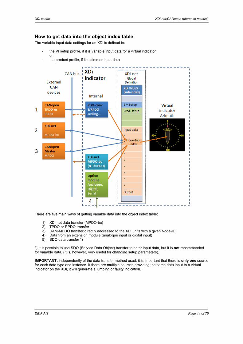
How to get data into the object index table The variable input data settings for an XDi is defined in:
- the VI setup profile, if it is variable input data for a virtual indicator or
- the product profile, if it is dimmer input data
There are five main ways of getting variable data into the object index table:
1) XDi-net data transfer (MPDO-bc) 2) TPDO or RPDO transfer 3) DAM-MPDO transfer directly addressed to the XDi units with a given Node-ID 4) Data from an extension module (analogue input or digital input) 5) SDO data transfer *)
*) It is possible to use SDO (Service Data Object) transfer to enter input data, but it is not recommended for variable data. (It is, however, very useful for changing setup parameters). IMPORTANT: independently of the data transfer method used, it is important that there is only one source for each data type and instance. If there are multiple sources providing the same data input to a virtual indicator on the XDi, it will generate a jumping or faulty indication.

XDi series XDi-net/CANopen reference manual
DEIF A/S Page 15 of 75
XDi-net data transfer To make data transfer easy and independent of Node-ID and other complicated configurations, XDi-net data is distributed using data broadcast. In XDi-net, PDO1 mode is configured as a SAM-MPDO (Source Address Mode Multiplexed PDO). Data is broadcast as an absolute (scaled) value from the data source, identified by its Node-ID and the data value is written directly into the pre-defined location for this data type/instance within the object index table (object index/sub-index) of the receiving XDi device. This SAM-MPDO broadcast is called the XDi-net Multiplexed PDO broadcast (MPDO-bc). When the data source for a virtual indicator is set up to be XDi-net, no further setup is needed; the indicator will simply receive the broadcast data directly. It does not need to know any COB-ID, source Node-ID or anything else, just plug and play.
Data distribution using DAM-MPDO In CANopen process, data may also be distributed using a “Destination Address Mode Multiplexed Process Data Object” (DAM-MPDO). DAM-MPDO data is addressed and sent from a CAN master or controller to each XDi individually. Like in XDi-net, data is routed directly into the defined object index/ sub-index. One of the RPDOs (2, 3 or 4) must be assigned as a DAM-MPDO channel, the default selection is made in the product profile and may be changed via the installation menu. DAM-PDO takes up more bandwidth in systems where many XDi indicators are presenting the same data, because data is sent to one indicator at a time. Note: the XDi requires variable data to be updated regularly, at least every 3 seconds (default). IMPORTANT: if XDi-net is active, restrictions apply to any other use of RPDO1 - see the section “XDi-net restrictions on CANopen”. IMPORTANT: when a data source is set up for XDi-net, it will receive either an XDi-net data broadcast or a DAM-MPDO data transfer. However, if XDi-net variable data is disabled in the product profile or via menu, then source data is limited to the DAM-MPDO transfer. In DAM-MPDO mode, the input source for an indicator (or a dimmer group) must be set up as XDi-net.
TPDO or RPDO as data carrier Transmit Process Data Object (TPDO) is very often used to transmit data from a CANopen-based sensor like a rudder angle transmitter (encoder). A TPDO contains a maximum of eight data bytes. The XDi supports the retraction of several mapped data types from the same TPDO, for example when: Actual pitch, %Pitch, Actual RPM and %RPM are mapped into the same TPDO using two bytes each. Receive Process Data Object (RPDO) is quite similar to TPDOs, and the XDi is able to use either type as input.
PDO converter The XDi software contains a number of “PDO converters” that are able to convert and route either a TPDO or an RPDO into the object index table. PDO converter setup parameters for variable input data are defined in the VI setup profile (VS), and dimmer input data is defined in the product profile (PP). A PDO converter receives the incoming data package contained in the defined TPDO (or RPDO), converts data using the default scaling rules from the setup profile and sends it as an absolute scaled data value to the defined object index location. The PDO converter may also be configured to pick one of several data packages out of a mapped PDO. The PDO converters are a very powerful tools, but it is a good idea to make a data structure before you start making a customised CAN solution using TPDO or RPDO broadcast. The XDi is also able to transmit data from the object index table carried in a TPDO. Either as single data type sent separately in a TPDO, or several data types can be mapped in one TPDO. Please note that data in the object index table is absolute values and cannot be scaled before transmission.

XDi series XDi-net/CANopen reference manual
DEIF A/S Page 16 of 75
TPDO and RPDO used for data broadcast The fact that the PDO converter in the XDi is able to receive and translate any of the TPDOs or RPDOs defined in CANopen makes it possible to use TPDOs and RPDOs for data broadcast. For each data type in use, you must assign either a unique RPDO or TPDO (TPDO1 if XL sCAN is also to be able to read it). Alternatively, define a unique mapping location for all used data types inside a TPDO or RPDO. Then an XDi unit on the CAN bus can be pre-configured to listen for precisely that TPDO or RPDO (and mapping) that contains the source data to be use. This will work as a data broadcast in line with the XDi-net, but it requires some work to define the structure of all TPDOs and/or RPDOs. Example A: the DEIF RTC 300 azimuth/rudder transmitter (encoder) is assigned Node-ID 1 and transmits the propeller angle data as a signed 16 bit integer (I16) mapped in byte 0 and 1 of TPDO1 – COB-ID 0x181. The XDi is set up to present azimuth virtual indicator 2 (VI002) designed for forward bridge and using VI setup 1 (VS01). In VS01, an azimuth PDO converter is assigned to receive and convert the azimuth angle data to the indicator. In this example, the RTC is set at 180 deg. and transmits value 0x7FFF, it is converted to an absolute angle value of 1800 (resolution 0.1) and stored in object index 0x3001-02. The virtual indicator azimuth disk pointer picks the absolute angle value (1800) from this index, presents it on the azimuth scale and, in addition, presents it in a digital readout as 180 deg. There are three other similar XDi units in the CAN network, one on each bridge wing. The ones on the wings must use the same indicator as above, VI002, and also the same VI setup, VS01. They will all receive the relative azimuth angle value directly from the RTC transmitter.
Alignment of TPDO data The data received in a TPDO (or RPDO) is available for all XDi units on the same CAN network, so normally data is not retransmitted using XDi-net broadcast. Instead any manual change of the PDO conversion parameters made via the XDi menu may be automatically synchronised with other XDi units on the CAN bus using the same TPDO, just select Y to “Synchronise parameter change on network” in the popup window when you leave the installation adjust menu. Example B: if a DEIF RTC 300 angle transmitter is not aligned correctly and has a zero offset, then this can be corrected via the XDi installation menu in one of the XDi units using this angle. When the adjustment is finished and you leave the menu, select “Yes” in the popup window to synchronise. Then the corrections are automatically sent via XDi-net to all other XDi units presenting this angle.
Integration with XL sCAN In systems where a combination of XDi and XL units (sCAN) is used, it can be beneficial to use the XDi as a data converter and router to supply calibrated and adjusted data to the XL units in the system. IMPORTANT: traditional XL indicators with sCAN interface do not support data mapping in a TPDO, data must be located in byte 0 and 1. Also note that sCAN only supports TPDO1. XL sCAN does not support TPDO adjustment synchronisation sent from an XDi. See alternative solution in example C below. Example C: the DEIF RTC 600 azimuth/rudder transmitter is used in a combined XDi and XL system. The XDi (Node-ID=17 (0x11)) is receiving relative angle data from the RTC (I16) located in COB-ID 0x181. The TPDO converter in the XDi translates the incoming angle to +/-500 (= +/-50.0 deg.) and transmits this on CAN using COB-ID 0x191 byte 0 and 1, to all the XL +/-50 deg. rudder indicators in the network. The XL must be set up with source ID 17 (sID = 17), and the scaling must be absolute where 50 deg. PS = -500; 0 deg. = 000; and 50 deg. SB = +500. After installation of the RTC on the rudder, alignment and calibration can be made directly in the XDi menu, and the angle value transmitted from this XDi will be aligned and calibrated correctly.

XDi series XDi-net/CANopen reference manual
DEIF A/S Page 17 of 75
Extension module data sharing Analogue or digital input signals from an AX1 or DX1 extension module are converted to absolute data values and/or % values and subsequently stored in the object index table, dependent on data type and instance. The conversion parameters are pre-configured in the VI setup profile for the selected virtual indicator.
Output - XDi-net data broadcast The converted analogue or digital data can be shared on CAN as an XDi-net broadcast; this is quite easy to use and always available in a VI setup profile that supports analogue or digital signals. The data that is sent out is the absolute (or %) data value from the object index table. All standard data is sent as a signed 16-bit value. An XDi with AX1 module snapped on acts as an analogue to CAN converter, and with a DX1 snapped on, the XDi acts as a digital to CAN converter (for example RPM from inductive pickup to CAN converter). Data will be available for all other XDi units on the CAN bus that are set up to use XDi-net data.
Output - TPDO/RPDO Alternatively, or in addition, the converted analogue and/or digital data may be sent in a TPDO or RPDO, however, this requires that support for T/RPDO output is pre-configured in the VI setup profile (VS). The data that is sent out is the absolute (or %) data value from the object index table. All standard data is sent as a signed 16-bit value. Up to four data types (2 bytes each) may be mapped into the same TPDO or RPDO, for example as input for other CAN devices on the bus. This must also be pre-configured in the VI setup profile. Note: unmapped transmission of TPDO1s is the method to use when XL sCAN indicators are integrated into the XDi system.
Overview of CAN data sources The following CAN input types can be used to source data into the object index: Data carrier
Absolute data
value *)
Relative data
value **)
CAN PDO converter used
Data can be manu-
ally adjust-ed ***)
Note
Routed Con-verter
XDi-net MPDO -bc
x Not recom-mended
o o No Data is absolute values and is routed directly to the multiplexer object index.
DAM-MPDO
x Not recom-mended
o o No Data is absolute values and is routed directly to the multiplexer object index.
TPDO/ RPDO
x o x o No Data is absolute values. The PDO converter is set up to route data to a defined ob-ject index. (No conversion).
TPDO/ RPDO
o x x x Yes Data is a relative value. The PDO converter is set up to convert to an absolute value and route it to a defined object index.
*) Absolute data means that the value represents the data directly; it is scaled according to the data definition for this index. **) Relative data may be scaled and off-set adjusted before it is stored in the object index as an absolute value. ***) Data can be manually adjusted from the XDi menu, and if you accept synchronisation when you leave the “Adjust” menu, the adjustments will be sent out to all other XDi units on the bus using the data value in this TPDO.

XDi series XDi-net/CANopen reference manual
DEIF A/S Page 18 of 75
Distribution of XDi data
Data distribution using XDi-net broadcast In XDi-net, data distribution between XDi units is broadcast from one source to all XDi nodes on the CAN bus that have the need for the broadcast data type and instance. The easy XDi-net plug and play is not only a protocol to use between XDi units, it can also be used in customer systems where PLCs or CAN controllers can use the XDi-net protocol to broadcast data to XDi indicators and avoid complicated setup.
Transmitting XDi-net data A unit transmitting XDi-net data must use RPDO1: COB-ID 0x200+Node-ID (its own RPDO1) to transmit XDi-net data, and the source address in the SAM-MPDO must be the unit’s own Node-ID. When “XDi-net variable data on:” in the product profile is set to have one or both CAN ports ON, then data is sent in COB-ID 0x200+Node-ID (range 0x200 to 0x27E).
Receiving XDi-net data When one or both CAN channels are selected for “XDi-net variable data on:” in the product profile, the XDi unit will listen for XDi-net data on the specified CAN port(s). When an XDi unit receives a SAM-RPD in any COB-ID from 0x200 to 0x27E, it will check that the source address is equal to the expected Node-ID, to which this COB-ID is reserved. For example, if the received RPDO1 has COB-ID: 0x260, the source Node-ID (address) in the MPDO must be 0x60; if not, the received SAM-PDO is ignored as “non XDi-net” compatible data. If data is received in RPDO1 for the special reserved service Node-ID 127with COB-ID: 0x27F, then the source address will be the transmitting unit’s own Node-ID, and therefore it is not checked. Note: such data may also be variable data from a very old XDi-net device that only transmits data in COB-ID: 0x27F; however, this should not be used for variable data broadcast since it may cause collisions if more than one node is sending periodic data. For occasional system calibration or synchronisation data, this is not a problem.
Customer systems’ use of XDi-net broadcast When SAM-MPDO broadcast (XDi-net) using 0x200 to 27E is used to broadcast variable data, it is very important that the data format and object index addressing is correct. The object index and sub-index used for each data type, including its resolution, will be available in the XDi library specification document. (This may be either the standard DEIF library specification or customer library specification).
CAN frame format for XDi-net broadcast The XDi-net broadcast protocol uses RPDO1 operated in SAM-MPDO mode. The COB-ID is 0x200+Node-ID. (One source to multiple receivers).

XDi series XDi-net/CANopen reference manual
DEIF A/S Page 19 of 75
BYTE 0: Bit 7: f = 0 The mode is SAM-MPDO Bits 0 to 6: 0x01 – 0x7F Source address is the Node-ID of the unit transmitting data BYTES 1-3: Field m is the multiplexer, where bytes 1 and 2 contain the object index number and byte 3 contains the sub-index number. BYTES 4-7: Data “d” contains the data value of the defined index/sub-index. If the index data is less than 32 bits, the range from MSB and up to 32 bit must be filled with 0s. (Data in an MPDO cannot be mapped).
Example 1: transmitting propeller RPM using XDi-net The virtual indicator below uses VI setup 1 (VS01), where the input source for the RPM bar graph and digital readout is defined as XDi-net broadcast of propeller RPM instance 1. This data type is located in object instance 0x3080+instance, in this case 0x3801, and the actual RPM data value is stored in sub-index 0x02 with a resolution of 0.1. (The resolution is fixed for each data type, it can be read from sub-index 0x03, in this case the value is -1 since resolution (R) is defined as x10R ). In normal operation, the XDi will listen for all RPDO1s that contain the propeller RPM instance 1 index.
In this example, the XDi receives data from a PLC with Node-ID 5 (0x05) using XDi-net broadcast (SAM-MPDO):
- The PLC sends RPM value 41.0 RPM to the indicator as a 16 bit signed value of 410 (0x019A) because the defined RPM resolution is 0.1 RPM.
- COB-ID for RPDO1, Node-ID 5 is 0x200-0x05=0x205 Transmit data type Propeller RPM COB-ID 0c200+ Node-ID
Byte 0 Address
Byte Index XLSB
Byte 2 Index XMSB
Byte 3 Sub-index
Byte 4 Value XLSB
Byte 5 Value XMSB
Byte 6 Don’t care
Byte 7 Don’t care
0x205 05 0x81 0x30 0x02 0x9A 0x01 0x00 0x00 The XDi will present the value 41.0 RPM on the bar graph and present RPM with 1 RPM resolution in the digital readout.

XDi series XDi-net/CANopen reference manual
DEIF A/S Page 20 of 75
Example 2: writing to a critical band using XDi-net protocol All standard variable data types in the XDi object index table have four sets of critical band data, this parameter may, as in this example, be used to mark restricted RPM sectors on an RPM scale where it is not preferable to run the engine, in this example shown as a red section inside the RPM bar graph. (See the picture below). Critical band can be designed into bar graphs and round indicators used in a virtual indicator, they can also be used to change pointer colour or bar graph colour. However, in order for it to work, the virtual indicator must be designed to support the desired critical band indication function. This example describes the use of XDi-net to make a global red sector setup.
Example of two pairs of critical bands used on bar graph
Object index addresses of critical bands In this example, the virtual indicator is designed with support for two critical bands, indicated as red sectors on the RPM bar graph. The data type RPM instance 1 is always located in index 0x3081. Critical band 1: 0x3081 at sub-index 0x0A (critical band 1 high) and 0x0B (critical band 1 low). Critical band 2: 0x3081 at sub-index 0x10 (critical band 1 high) and 0x11 (critical band 2 low). (Note: up to four critical bands may be defined for an indicator).
Setup/activation of critical bands The default parameter value of the critical band is 0x7FFF . When the index holds this value, the critical band is not activated. When an absolute value is written to one of the indexes, the critical band will be shown on the graph. If both values high and low for a band hold the same value, then the band will be invisible. Scaling of the critical band value is the same as the scaling used for absolute data. Example: writing to critical band From the CAN controller with Node-ID=0x01, the following must be set up: When a critical band from 25 to 40 is desired, it is possible to use either critical band 1 or critical band 2. Here the critical band 1 is chosen, and the additional critical band is then placed from 50 to 70. (RPM data resolution is default = 0.1, so critical band data to send is 250 (0x00FA), 400(0x0190) , 500 (0x01F4) and 700(0x02BC). The XDi-net commands used to place the two bands are shown in the tables below.

XDi series XDi-net/CANopen reference manual
DEIF A/S Page 21 of 75
Set the value for critical band 1 low at 25.0 RPM (0x00FA) in sub-index 0x3081-0B: Critical band 1 lowCOB-ID 0c200+ Node-ID
Byte 0 Addr.
Byte 1 Index XLSB
Byte 2 Index XMSB
Byte 3 Sub-index
Byte 4 Value XLSB
Byte 5 Value XMSB
Byte 6 Don’t care
Byte 7 Don’t care
0x201 0x01 0x81 0x30 0x0B 0xFA 0x00 0xFF 0xFF Set the value for critical band 1 high at 40.0 RPM (0x0190) in sub-index 0x3081-0B: Critical band 1 highCOB-ID 0c200+ Node-ID
Byte 0 Addr.
Byte 1 Index XLSB
Byte 2 Index XMSB
Byte 3 Sub-index
Byte 4 Value XLSB
Byte 5 Value
Byte 6 Don’t care
Byte 7 Don’t care
0x201 0x01 0x81 0x30 0x0B 0x90 0x01 0xFF 0xFF Set the value for critical band 2 low at 500 RPM (0x01F4) in sub-index 0x3081-10: Critical band 2 lowCOB-ID 0c200+ Node-ID
Byte 0 Addr.
Byte 1 Index XLSB
Byte 2 Index XMSB
Byte 3 Sub-index
Byte 4 Value XLSB
Byte 5 Value XMSB
Byte 6 Don’t care
Byte 7 Don’t care
0x201 0x01 0x81 0x30 0x11 0xF4 0x01 0xFF 0xFF Set the value for critical band 2 high at 700 RPM (0x02BC) in sub-index 0x3081-11: Critical band 2 high COB-ID 0c200+ Node-ID
Byte 0 Addr.
Byte 1 Index XLSB
Byte 2 Index XMSB
Byte 3 Sub-index
Byte 4 Value XLSB
Byte 5 Value
Byte 6 Don’t care
Byte 7 Don’t care
0x201 0x01 0x81 0x30 0x10 0xBC 0x02 0xFF 0xFF The XDi-net setup commands above are broadcast to all XDi units on the CAN bus, therefore they will all be set up to use the same critical band values for the data type RPM instance 1. Note: a DAM-MPDO (if activated) or an SDO may also be used to set the critical band parameters, but it will be a unit-by-unit setup, not a global setup. (If you use SDO, then remember to unlock first).
Product parameter setup via CAN
Manufacturer-specific object index The whole backbone of the XDi is the manufacturer-specific section of the CANopen object index table; this makes it possible to control more or less all key functions of the XDi via SDO communication on CAN. To protect the XDi configuration from unintentional parameter changes, the SDO communication is protected by a lock/unlock procedure. The grouping of the manufacturer-specific sector from 0x2000 to 0x5FFF is illustrated in the table below: XDi index 0x2000 – 0x5FFF
Max. # objects
Instance
Object types Note
0x2000 – 0x2FFF 4096 System and main control parameters Only indexes in appendix must be accessed
0x3000 – 0x3FFF 4096 Variable XDi input/output data Global parameters 0x4000 – 0x4FFF 4096 Product parameters Specific for this XDi unit 0x5000 – 0x5FFF 4096 RESERVED/RESTRICTED Must not be accessed

XDi series XDi-net/CANopen reference manual
DEIF A/S Page 22 of 75
0x2000 parameters Parameters in the 0x2000 group are system-specific parameters. Most of these parameters are not relevant for normal operation, setup and control of an XDi system. The relevant parameters in the 0x2000 group can be found in Appendix 2. IMPORTANT: indexes that are not listed in the appendix must not be accessed or changed.
0x4000 parameters Object indexes 0x4000 to 0x4FFF contain product-specific parameters like:
- Product type - Software and hardware version - Library information and version - Selected virtual indicator and setup profiles - Command for automated setup - VI headline selection and text - VI label selection and text - VI unit selection
This type of control parameters can be used by a CAN controller to automatically configure the XDi during installation or afterwards in a service situation. The list of relevant 0x4000 parameters is located in Appendix 4.
SDO write protection It is only possible to change parameter values in the 0x2000 or 0x4000 sections in the object index table by using SDO communication, and since changes may seriously affect the operation of the XDi, the SDO write function is protected extra by a special lock and unlock function. The lock (SDO write protection) is enabled by default. Before you write new data into an index/sub-index, it is required to unlock (disable the SDO write lock). The unlock function has an adjustable timeout (default 5 seconds); if there is no SDO communication when the time runs out, the XDi will automatically lock the SDO write function again. It is possible to change the automatic timeout from 1 to 65 sec. Setting the timeout to 0 will disable the timeout function. In this case it is important to send a lock command when SDO communication is finalised. IMPORTANT: it is not recommended to disable the automatic SDO write lock function, as this may leave the XDi open for accidental or unintentional changes of parameters. Note: the protection does not affect the possibility to read indexes by using an SDO read request.
SDO write protection index
Index - sub Description Default value 0x401F-01 Locking/unlocking
of SDO write 0x80000000 0x7FFFFFFF: normal unlocked SDO write operation.
0x80000000: all manufacturer-specific object indexes (0x2000…0x5FFF) are blocked for SDO write operations (except the SDO protection object index 0x401F itself).
0x401F-02 SDO write protection timeout
5000 0: no timeout on SDO write operation. SDO write operation is only controlled by sub-index 0x01. >0: timeout in [ms]. When the time that has passed since the last successful SDO write exceeds the timeout, sub-index 0x01 is forced to: 0x80000000. Values 1…999 are forced to 1000, to ensure minimum 1 sec. timeout.
SDO write unlock procedure Send the unlock code 0x7FFFFFFF to index 0x401F-01 by using SDO write.

XDi series XDi-net/CANopen reference manual
DEIF A/S Page 23 of 75
Make the changes you want to make by using SDO read/write commands. When you have finalised the SDO write communication with the XDi unit, it will still be open for accidental changes for another 5 seconds, before the automatic lock function will set the value of index 0x401F-01 to 0x80000000 (locked). If a timeout longer that 5000 ms is needed, the timeout should be changed before unlock.
Note: to lock the XDi immediately after finishing SDO writing, you must send the lock command 0x80000000 to index 0x401F- 01. This is also the correct procedure to use if automatic activation of protection is disabled. Note: you may at any time read the lock code in index 0x401F- 01 to determine whether or not the XDi is locked.
Examples of the SDO commands used The Node-ID for the XDi in the following example: 0x79 (=121) Read timeout value
COB-ID Byte 0 Byte 1 Byte 2 Byte 3 Byte 4 Byte 5 Byte 6 Byte 7 0x600+ Node-ID
Read Obj. index (LSB)
Obj. index(MSB)
Sub-index
Data value (LSB)
Data value (MSB)
Don’t care Don’t care
0x679 0x40 0x1F 0x40 0x02 0x00 0x00 0x00 0x00 Response from XDi:
COB-ID Byte 0 Byte 1 Byte 2 Byte 3 Byte 4 Byte 5 Byte 6 Byte 7 0x580+ Node-ID
Response Obj. index (LSB)
Obj. index(MSB)
Sub-index
Resp. Resp. Resp. Resp.
0x5F9 0x60 0x1F 0x40 0x02 0x60 0xEA 0x00 0x00
The timeout value is 0xEA60, equal to 60000 ms.
Write protection is automatically set when timeout is exceeded.
0x401F-02
Write SDO command before timeout is
exceeded.
Set unlock in 0x401F-01

XDi series XDi-net/CANopen reference manual
DEIF A/S Page 24 of 75
Change the timeout value Change value to 0x0000, this will disable timeout.
COB-ID Byte 0 Byte 1 Byte 2 Byte 3 Byte 4 Byte 5 Byte 6 Byte 7 0x600+ Node-ID
Write Obj. index (LSB)
Obj. index(MSB)
Sub-index
Data value (LSB)
Data value (MSB)
Don’t care Don’t care
0x679 0x2B 0x1F 0x40 0x02 0x00 0x00 0x00 0x00 Response from XDi:
COB-ID Byte 0 Byte 1 Byte 2 Byte 3 Byte 4 Byte 5 Byte 6 Byte 7 0x580+ Node-ID
Response Obj. index (LSB)
Obj. index(MSB)
Sub-index
Resp. Resp. Resp. Resp.
0x5F9 0x60 0x1F 0x40 0x02 0x00 0x00 0x00 0x00
Set SDO protection to unlock
COB-ID Byte 0 Byte 1 Byte 2 Byte 3 Byte 4 Byte 5 Byte 6 Byte 7 0x600+ Node-ID
Write Obj. index (LSB)
Obj. index(MSB)
Sub-index
Data value (LSB)
Data value
Data value
Data value (MSB)
0x679 0x23 0x1F 0x40 0x01 0xFF 0xFF 0xFF 0x7F Data value: 0x7FFFFFFF. Response from XDi:
COB-ID Byte 0 Byte 1 Byte 2 Byte 3 Byte 4 Byte 5 Byte 6 Byte 7 0x580+ Node-ID
Response Obj. index (LSB)
Obj. index(MSB)
Sub-index
Resp. Resp. Resp. Resp.
0x5F9 0x60 0x1F 0x40 0x01 0xFF 0xFF 0xFF 0xFF
Set SDO protection to lock
COB-ID Byte 0 Byte 1 Byte 2 Byte 3 Byte 4 Byte 5 Byte 6 Byte 7 0x600+ Node-ID
Write Obj. index (LSB)
Obj. index(MSB)
Sub-index
Data value (LSB)
Data value
Data value
Data value (MSB)
0x679 0x23 0x1F 0x40 0x01 0x00 0x00 0x00 0x80 Data value: 0x80000000. Response from XDi:
COB-ID Byte 0 Byte 1 Byte 2 Byte 3 Byte 4 Byte 5 Byte 6 Byte 7 0x580+ Node-ID
Response Obj. index (LSB)
Obj. index(MSB)
Sub-index
Resp. Resp. Resp. Resp.
0x5F9 0x60 0x1F 0x40 0x01 0x00 0x00 0x00 0x80
XDi series XDi-net/CANopen reference manual
DEIF A/S Page 25 of 75
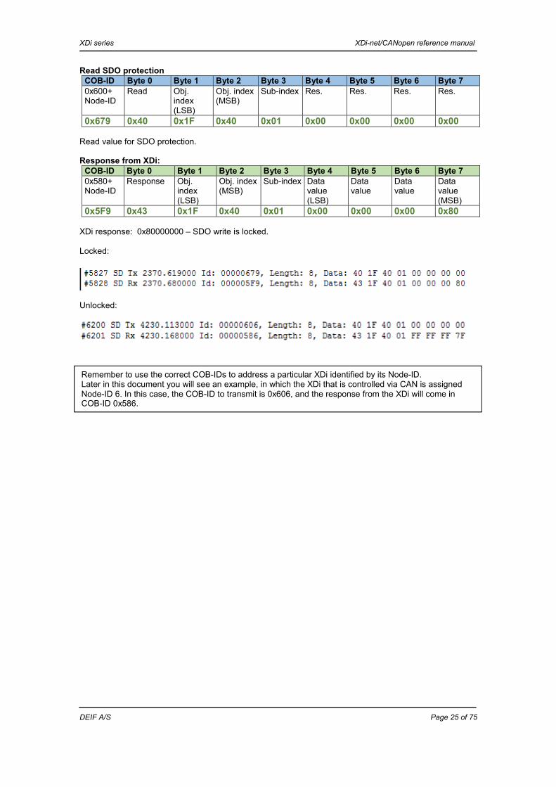
Read SDO protection COB-ID Byte 0 Byte 1 Byte 2 Byte 3 Byte 4 Byte 5 Byte 6 Byte 7 0x600+ Node-ID
Read Obj. index (LSB)
Obj. index(MSB)
Sub-index
Res. Res. Res. Res.
0x679 0x40 0x1F 0x40 0x01 0x00 0x00 0x00 0x00 Read value for SDO protection. Response from XDi:
COB-ID Byte 0 Byte 1 Byte 2 Byte 3 Byte 4 Byte 5 Byte 6 Byte 7 0x580+ Node-ID
Response Obj. index (LSB)
Obj. index(MSB)
Sub-index
Data value (LSB)
Data value
Data value
Data value (MSB)
0x5F9 0x43 0x1F 0x40 0x01 0x00 0x00 0x00 0x80 XDi response: 0x80000000 – SDO write is locked. Locked:
Unlocked:
Remember to use the correct COB-IDs to address a particular XDi identified by its Node-ID. Later in this document you will see an example, in which the XDi that is controlled via CAN is assigned Node-ID 6. In this case, the COB-ID to transmit is 0x606, and the response from the XDi will come in COB-ID 0x586.

XDi series XDi-net/CANopen reference manual
DEIF A/S Page 26 of 75
Automated XDi start-up configuration via CANopen It is possible to implement what we call a “base master” (BM) configuration function in a CANopen master or CAN controller (PLC) to automatically make system configuration of XDi units in a CAN bus system. The only requirement is that each XDi is assigned a Node-ID and that the controller knows the configuration parameters for each node. Node-ID is the first selection in the XDi start-up wizard, and when the Node-ID is selected, the XDi will send a message that it is on the bus and ready to be set up. When this message is received, the controller should immediately take over and make the configuration via CAN. The installer will not even see the rest of the steps in the wizard before the XDi boots up again with the automatically selected virtual indicator and setup profiles.
Automated configuration of a service device Integrating automated configuration in your CAN controller will also open up easy service replacement of the XDi. A faulty XDi in a system can just be replaced by a new XDi unit, assigned the same Node-ID as the old faulty unit. Now the CAN controller can take over and configure the new service unit via CAN. An XDi from a non-critical location can also be used as a replacement unit, if an XDi at a more critical location is faulty. Just perform a master reset to factory settings, and it will be as good as new. Remember: write the Node-ID number on the label behind the front frame on all XDi units in the system. The Node-ID is then easily available in a service situation.
Fully automated setup after replacement of a faulty XDi The scenario is that the technician on board replaces a faulty XDi with an XDi in “service unit mode”. Any XDi can be brought into “service unit mode” simply by making a master reset to “service unit”. In this mode the XDi is “parked” on the service node (Node-ID 127) and reset to factory settings, and the start-up wizard is shown. In addition, it sends heartbeat (must be active) to indicate its presence on the CAN bus. The BM controller monitors all XDi units on the CAN bus by their heartbeat and detects that the replaced XDi Node is no longer available, but a service unit is present on Node127. The BM controller is now able to shift the Node-ID of the “XDi service unit” to the Node-ID that was detected to be lost. The Node-ID shift is performed using CANopen LLS procedure, and immediately after the controller makes the automated configuration of the new XDi service device. Replacement of one faulty unit can be fully automatic; if more than one unit is missing on the CAN bus, the installer may have to decide the order of replacement.
Procedure for automated indicator setup When an XDi is installed in a CAN network and powered up the first time, the start-up wizard will automatically start and ask for a Node-ID. As soon as the Node-ID is assigned, the XDi will send an emergency message on CAN:
Alarm type When Duration
Error register Obj. in 0x1001
Emer-gency error code
CAN manufacturer- specific error code in EMCY Warning Byte 3
Alert Byte 4
Emergency Setup wizard is active and Node-ID is assigned
While setup wizard is active
0x81 0xFF00 0xFF 0xFF
XDi series XDi-net/CANopen reference manual
DEIF A/S Page 27 of 75
When a CAN master or CAN controller detects this message on the CAN bus, it can start an auto-configuration process as follows:
1) Read 0x1018, sub-index 0x01 to verify that the vendor ID is DEIF: 0x0000B2 and that the DPM code is 0x10 (standard XDi-net product). Then read sub-index 0x02 to verify that it is the correct XDi size (for example 0x02 = XDi144) and performance class (0x00 = Single, 0x01 = Dual, 0x02 = Multi).
2) If 1) is OK, read index 0x4001, sub-indexes 0x02, 0x03, 0x05 and 0x07 to verify that the XDi contains the correct library.
3) If 2) is OK, unlock the XDi for SDO write (see unlock procedure). 4) If the XDi is mounted upside down, send value 0x01 to the 180o rotation index 0x400B-04. This
must be done even if the XDi starts up in “upside down mode”. (You may also rotate the display presentation manually after setup, or later via the user menu).
5) Write the desired VI, VS and PP numbers to the XDi in index 0x4007-01(configuration command). 6) The XDi will reboot and start up in normal mode with the desired indicator setup.
To verify setup from the CAN controller:
7) Wait until heartbeat is received from the XDi after boot-up. 8) Read 0x4007-01, if it reads 0x00000000 the setup process was successful.
If it reads 0xFFFFFFFF, the configuration has failed, for example because the selected PP, VI or VS does not exist. (If it reads the same configuration that you just sent, it is because you have not changed anything and the XDi has not rebooted either).
9) If 8) is OK, you may read the active VI number in 0x4002-02, the active VI setup number in 0x4002-11 and the active product profile number in 0x4003-02 and compare the result with the desired selection made in 5).
10) If 9) is OK, the setup is successfully completed. 11) The lock function (SDO write protection) will activate automatically after timeout (or you can send
the lock command to terminate timeout).
XDi series XDi-net/CANopen reference manual
DEIF A/S Page 28 of 75
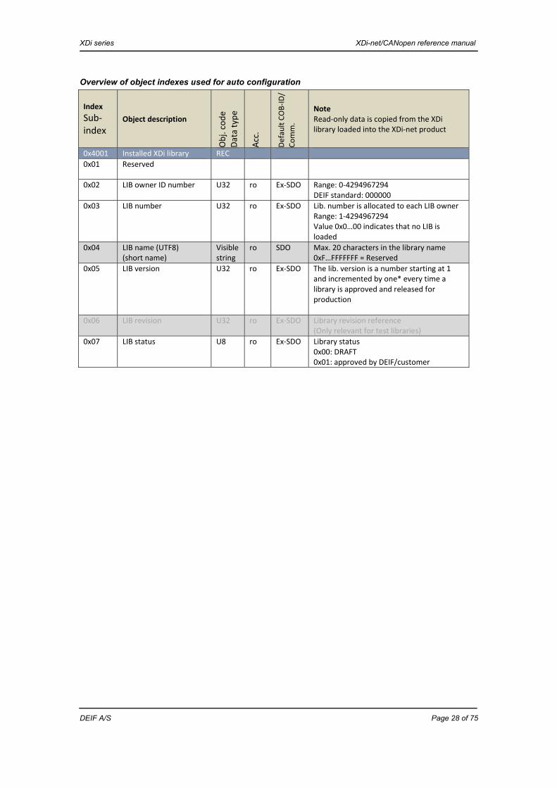
Overview of object indexes used for auto configuration
Index Sub-index
Object description
Obj.
code
Da
ta ty
pe
Acc.
Defa
ult C
OB-
ID/
Com
m.
Note Read-only data is copied from the XDi library loaded into the XDi-net product
0x4001 Installed XDi library REC 0x01 Reserved
0x02 LIB owner ID number U32 ro Ex-SDO Range: 0-4294967294 DEIF standard: 000000
0x03 LIB number U32 ro Ex-SDO Lib. number is allocated to each LIB owner Range: 1-4294967294 Value 0x0…00 indicates that no LIB is loaded
0x04 LIB name (UTF8) (short name)
Visible string
ro SDO Max. 20 characters in the library name 0xF…FFFFFFF = Reserved
0x05 LIB version U32 ro Ex-SDO The lib. version is a number starting at 1 and incremented by one* every time a library is approved and released for production
0x06 LIB revision U32 ro Ex-SDO Library revision reference (Only relevant for test libraries)
0x07 LIB status U8 ro Ex-SDO Library status 0x00: DRAFT 0x01: approved by DEIF/customer

XDi series XDi-net/CANopen reference manual
DEIF A/S Page 29 of 75
0x4007 OD status handling 0x01 Select indicator and
setup U32 wo Ex-SDO Setup PP (product profile), VI (virtual
indicator) and VS (virtual indicator setup) Byte 0: VS 1-255 Bytes 1-2: VI 1-65535 Byte 3: PP 1-255 Value will be set to command status when the command has been executed (after less than 30 seconds) Command status: 0xFFFFFFFF: ERROR 0x00000000: idle (new setup has been executed) 0xXXYYYYZZ: setup not changed (XX = old VS, YYYY = old VI, ZZ = old PP. XDi already has this setup)
…. 0x400B Product sound and
display setup
… 0x04 Display rotation
Normal/up-side down U8 rw Ex-SDO 0x00 = Normal
0x01 = Up-side down (rotated 180 deg.) Rest is reserved
Index Sub-index
Object description
Obj.
code
Dat
a ty
pe
Acc.
Defa
ult C
OB-
ID/
Com
m.
Note Read-only data is copied from the XDi library loaded into the XDi-net product
0x4002 Virtual indicator and VI setup selection
REC
0x01 Total number of virtual indicators in LIB
U16 ro Ex-SDO Normally up to 100 VIs in one LIB Range: 1-65534 0 indicates that no VIs are available in LIB 0xFFFF is reserved
0x02 Active virtual indicator number
U16 rw Ex-SDO
Virtual indicator setup: 0x10 Total number of VI
setup (VS) files for the active VI
U16 ro Ex-SDO Normally max. 50 VI setups for one virtual indicator Range: 1-65534 0 indicates that no VI setup is available in the LIB 0xFFFF is reserved
0x11 Active VI setup (VS) file number
U16 rw Ex-SDO
0x4003 Product profile: REC 0x01 Total number of
product profiles (PP) in this LIB
U16 ro Ex-SDO Normally max. 50 product profiles in one XDi LIB Range: 1-65534 0 indicates that no PP is available in LIB 0xFFFF is reserved
0x02 Active PP file number U16 rw Ex-SDO

XDi series XDi-net/CANopen reference manual
DEIF A/S Page 30 of 75
Example - automated configuration via CAN An XDi 144 Multi is powered up for the first time on the CAN bus with a CAN controller (Node-ID 1) with automatic configuration. The installer has selected Node-ID: 6 (0x06) in the first step of the XDi start-up wizard. Immediately after, the XDi sends out an emergency message on CAN, indicating that Node-ID: 0x06 is on the bus, but not configured.
Emergency message – XDi is not set up COB-ID
Byte 0 Byte 1 Byte 2 Byte 3 Byte 4 Byte 5 Byte 6 Byte 7
0x080+ Node-ID
Emrg. Error code (LSB)
Emrg. Error code (MSB)
Error register
Manuf. spec.
Manuf. spec.
Manuf. spec. (Not used)
Manuf. spec. (Not used)
Manuf. spec. (Not used)
0x086 0x00 0xFF 0x81 0xFF 0xFF 0x00 0x00 0x00 On receipt of this message, the CAN controller (Node-ID 1) takes over. The controller has the configuration for Node-ID 6 stored:
- The XDi at node 6 must be set up to use: PP 02, VI 014 and VS 03 - XDi must be type: XDi 144 (size 0x02) and type Multi (performance type 0x03) - XDi must have a pre-loaded library identified by: owner: 400413 (0x061c1d), Lib. no. 02 version
100 (0x64) - Library must be the approved version (the one released for production - not a draft library).
The CAN controller can now run the automated setup process using Expedited SDO communication:
In the following steps, use the SDO read procedure to read the indexes (XXXX)/sub-indexes (YY): COB-ID Byte 0 Byte 1 Byte 2 Byte 3 Byte 4 Byte 5 Byte 6 Byte 7 0x600+ Node-ID
Read Obj. index (LSB)
Obj. index (MSB)
Sub-index
Res. Res. Res. Res.
0x606 0x40 0xXX 0xXX 0xYY 0x00 0x00 0x00 0x00
1. Read index 0x1018, sub-index 0x01 using SDO exp. upload:
COB-ID Byte 0 Byte 1 Byte 2 Byte 3 Byte 4 Byte 5 Byte 6 Byte 7 0x600+ Node-ID
Read Obj. index (LSB)
Obj. index (MSB)
Sub-index
Res. Res. Res. Res.
0x606 0x40 0x18 0x10 0x01 0x00 0x00 0x00 0x00 COB-ID
Byte 0 Byte 1 Byte 2 Byte 3 Byte 4 Byte 5 Byte 6 Byte 7
0x580+ Node-ID
Read response
Obj. index (LSB)
Obj. index (MSB)
Sub-index
Data (LSB)
Vendor ID (LSB)
Data Vendor ID
Data Vendor ID (MSB)
Data (MSB) DPM code
0x586 0x43 0x18 0x10 0x01 0xB2 0x00 0x00 0x10
Now verify that the vendor ID is DEIF: 0x0000B2 and that the DPM code is 0x10 (standard XDi-net product).
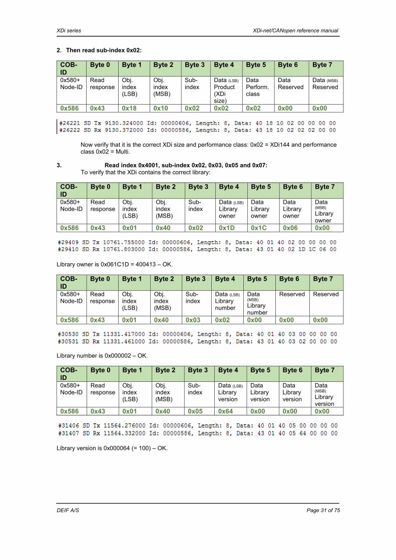
XDi series XDi-net/CANopen reference manual
DEIF A/S Page 31 of 75
2. Then read sub-index 0x02:
COB-ID
Byte 0 Byte 1 Byte 2 Byte 3 Byte 4 Byte 5 Byte 6 Byte 7
0x580+ Node-ID
Read response
Obj. index (LSB)
Obj. index (MSB)
Sub-index
Data (LSB)
Product (XDi size)
Data Perform. class
Data Reserved
Data (MSB)
Reserved
0x586 0x43 0x18 0x10 0x02 0x02 0x02 0x00 0x00
Now verify that it is the correct XDi size and performance class: 0x02 = XDi144 and performance class 0x02 = Multi.
3. Read index 0x4001, sub-index 0x02, 0x03, 0x05 and 0x07: To verify that the XDi contains the correct library:
COB-ID
Byte 0 Byte 1 Byte 2 Byte 3 Byte 4 Byte 5 Byte 6 Byte 7
0x580+ Node-ID
Read response
Obj. index (LSB)
Obj. index (MSB)
Sub-index
Data (LSB)
Library owner
Data Library owner
Data Library owner
Data (MSB) Library owner
0x586 0x43 0x01 0x40 0x02 0x1D 0x1C 0x06 0x00
Library owner is 0x061C1D = 400413 – OK.
COB-ID
Byte 0 Byte 1 Byte 2 Byte 3 Byte 4 Byte 5 Byte 6 Byte 7
0x580+ Node-ID
Read response
Obj. index (LSB)
Obj. index (MSB)
Sub-index
Data (LSB)
Library number
Data (MSB) Library number
Reserved Reserved
0x586 0x43 0x01 0x40 0x03 0x02 0x00 0x00 0x00
Library number is 0x000002 – OK.
COB-ID
Byte 0 Byte 1 Byte 2 Byte 3 Byte 4 Byte 5 Byte 6 Byte 7
0x580+ Node-ID
Read response
Obj. index (LSB)
Obj. index (MSB)
Sub-index
Data (LSB)
Library version
Data Library version
Data Library version
Data (MSB) Library version
0x586 0x43 0x01 0x40 0x05 0x64 0x00 0x00 0x00
Library version is 0x000064 (= 100) – OK.

XDi series XDi-net/CANopen reference manual
DEIF A/S Page 32 of 75
COB-ID
Byte 0 Byte 1 Byte 2 Byte 3 Byte 4 Byte 5 Byte 6 Byte 7
0x580+ Node-ID
Read response
Obj. index (LSB)
Obj. index (MSB)
Sub-index
Data (LSB)
Library status
0x586 0x4F 0x01 0x40 0x07 0x01
Library status is 0x01 = approved (= released) – OK.
All preconditions are OK to continue the setup process!
1. Unlock the XDi for SDO write (see description in chapter “SDO write unlock procedure”). 2. If the XDi is mounted upside down, write the 180o rotation command 0x01 to 0x400B-04:
COB-ID Byte 0 Byte 1 Byte 2 Byte 3 Byte 4 Byte 5 Byte 6 Byte 7 0x600+ Node-ID
Write Obj. index (LSB)
Obj. index(MSB)
Sub-index
Data (LSB)
Line no. Don’t care
Don’t care
Don’t care
0x606 0x2F 0x0B 0x40 0x04 0x01 - - - Note: must always be sent if the XDi is mounted upside down.
3. Write the desired VI, VS and PP numbers in the configuration command, index 0x4007-01:
COB-ID Byte 0 Byte 1 Byte 2 Byte 3 Byte 4 Byte 5 Byte 6 Byte 7 0x600+ Node-ID
Write Obj. index (LSB)
Obj. index (MSB)
Sub-index
Data (LSB) VS
Data VI (LSB)
Data VI (MSB)
Data (MSB)
PP
0x606 0x23 0x07 0x40 0x01 0x01 0x09 0x00 0x01 PP 01 (0x01), VI 009 (0x0009) and VS 01 (0x01).
4. The XDi will reboot and start up with the selected settings. It may take several seconds before the reboot and setup are finalised and the XDi can return the status command. (The XDi will make 3 beeps when it is up and running again).
5. Listen for heartbeat from Node 6 – when heartbeat is received, you can continue.
6. Verify that configuration was successful: To verify that the setup is performed correctly. Read 0x4007-01 = setup has been executed, or 0xFFFFFFFF = setup has failed, for example the selected PP, VI or VS may not exist.
COB-ID Byte 0 Byte 1 Byte 2 Byte 3 Byte 4 Byte 5 Byte 6 Byte 7 0x580+ Node-ID
Read response
Obj. index (LSB)
Obj. index (MSB)
Sub-index
Data (LSB)
Data
Data
Data (MSB)
0x586 0x43 0x07 0x40 0x01 0x00 0x00 0x00 0x00 Status is 0x00000000: setup is successfully completed. Status: 0xFFFFFFFF = setup has failed, for example the selected PP, VI or VS does not exist. Note: if you write the configuration command with the exact same selection of VI, VS and PP as the XDi is already configured to use (= no change), it will not reboot, and when reading 0x4007-01, the response will be exactly the VI, VS and PP that were just written (not the command status: 0x00000000 or 0xFFFFFFFF).
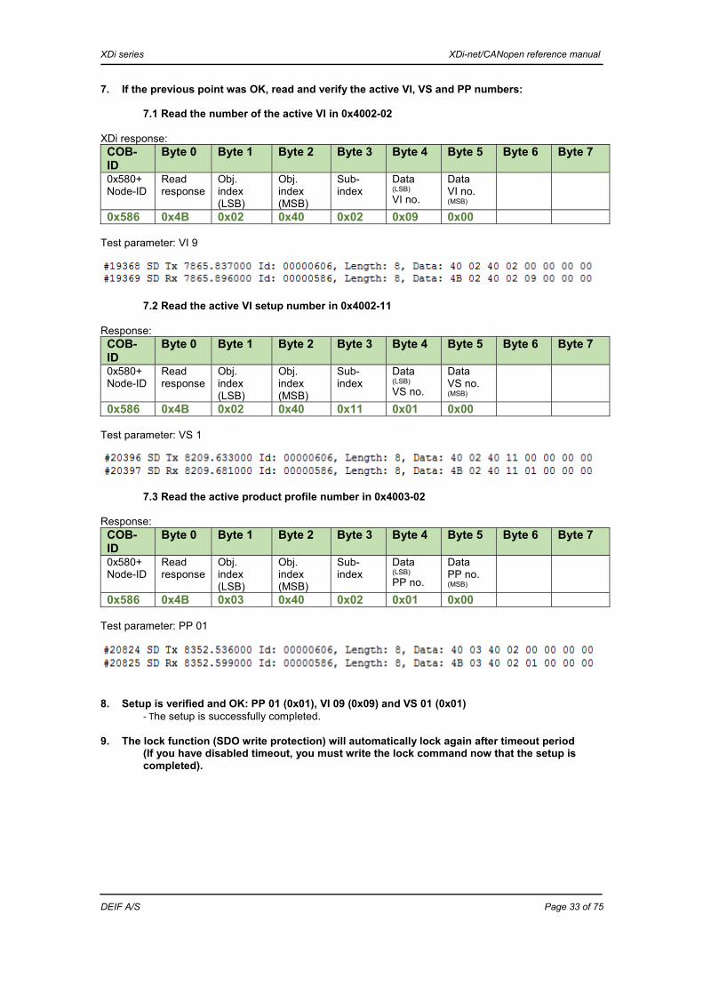
XDi series XDi-net/CANopen reference manual
DEIF A/S Page 33 of 75
7. If the previous point was OK, read and verify the active VI, VS and PP numbers: 7.1 Read the number of the active VI in 0x4002-02
XDi response: COB-ID
Byte 0 Byte 1 Byte 2 Byte 3 Byte 4 Byte 5 Byte 6 Byte 7
0x580+ Node-ID
Read response
Obj. index (LSB)
Obj. index (MSB)
Sub-index
Data (LSB) VI no.
Data VI no. (MSB)
0x586 0x4B 0x02 0x40 0x02 0x09 0x00
Test parameter: VI 9
7.2 Read the active VI setup number in 0x4002-11
Response: COB-ID
Byte 0 Byte 1 Byte 2 Byte 3 Byte 4 Byte 5 Byte 6 Byte 7
0x580+ Node-ID
Read response
Obj. index (LSB)
Obj. index (MSB)
Sub-index
Data (LSB) VS no.
Data VS no. (MSB)
0x586 0x4B 0x02 0x40 0x11 0x01 0x00 Test parameter: VS 1
7.3 Read the active product profile number in 0x4003-02
Response: COB-ID
Byte 0 Byte 1 Byte 2 Byte 3 Byte 4 Byte 5 Byte 6 Byte 7
0x580+ Node-ID
Read response
Obj. index (LSB)
Obj. index (MSB)
Sub-index
Data (LSB) PP no.
Data PP no. (MSB)
0x586 0x4B 0x03 0x40 0x02 0x01 0x00
Test parameter: PP 01
8. Setup is verified and OK: PP 01 (0x01), VI 09 (0x09) and VS 01 (0x01)
- The setup is successfully completed.
9. The lock function (SDO write protection) will automatically lock again after timeout period (If you have disabled timeout, you must write the lock command now that the setup is completed).
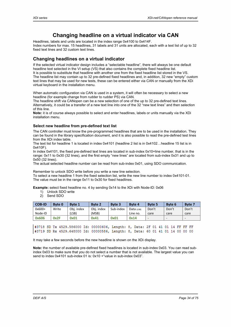
XDi series XDi-net/CANopen reference manual
DEIF A/S Page 34 of 75
Changing headline on a virtual indicator via CAN Headlines, labels and units are located in the index range 0x4100 to 0x414F. Index numbers for max. 15 headlines, 31 labels and 31 units are allocated, each with a text list of up to 32 fixed text lines and 32 custom text lines.
Changing headlines on a virtual indicator If the selected virtual indicator design includes a “selectable headline”, there will always be one default headline text selected in the VI setup (VS) that also contains the complete fixed headline list. It is possible to substitute that headline with another one from the fixed headline list stored in the VS. The headline list may contain up to 32 pre-defined fixed headlines and, in addition, 32 new “empty” custom text lines that may be used for new tests, these can be entered either via CAN or manually from the XDi virtual keyboard in the installation menu. When automatic configuration via CAN is used in a system, it will often be necessary to select a new headline (for example change from rudder to rudder PS) via CAN. The headline shift via CANopen can be a new selection of one of the up to 32 pre-defined text lines. Alternatively, it could be a transfer of a new text line into one of the 32 “new text lines” and then selection of this line. Note: it is of course always possible to select and enter headlines, labels or units manually via the XDi installation menu.
Select new headline from pre-defined text list The CAN controller must know the pre-programmed headlines that are to be used in the installation. They can be found in the library specification document, and it is also possible to read the pre-defined test lines from the XDi index table. The text list for headline 1 is located in index 0x4101 (headline 2 list is in 0x4102…headline 15 list is in 0x410F). In index 0x4101, the fixed pre-defined text lines are located in sub-index 0x10+line number, that is in the range: 0x11 to 0x30 (32 lines), and the first empty “new lines” are located from sub-index 0x31 and up to 0x50 (32 lines). The actual selected headline number can be read from sub-index 0x01, using SDO communication. Remember to unlock SDO write before you write a new line selection. To select a new headline 1 from the fixed selection list, write the new line number to index 0x4101-01. The value must be in the range 0x11 to 0x30 for fixed headlines. Example: select fixed headline no. 4 by sending 0x14 to the XDi with Node-ID: 0x06
1) Unlock SDO write 2) Send SDO
COB-ID Byte 0 Byte 1 Byte 2 Byte 3 Byte 4 Byte 5 Byte 6 Byte 7 0x600+ Node-ID
Write Obj. index (LSB)
Obj. index(MSB)
Sub-index
Data (LSB)
Line no. Don’t care
Don’t care
Don’t care
0x606 0x2F 0x01 0x41 0x01 0x14 - - -
It may take a few seconds before the new headline is shown on the XDi display. Note: the number of available pre-defined fixed headlines is located in sub-index 0x03. You can read sub-index 0x03 to make sure that you do not select a number that is not available. The largest value you can send to index 0x4101 sub-index 01 is: 0x10 +“value in sub-index 0x03”.
XDi series XDi-net/CANopen reference manual
DEIF A/S Page 35 of 75
Write new custom headline text to the XDi and select it New custom headlines can be written in the index range 0x4101-31 (0x31 is the first custom text line) to 0x4101-50 (32 lines in total). The text format is UTF8 (Unicode type with variable length characters). Reading and writing text to these indexes requires implementation of SDO block upload and download in the CAN controller that makes the automatic setup via CAN. It is recommended to use a CAN management tool or software module for this operation. For testing, DEIF engineers have used “Device Manager software”. Remember to unlock SDO write. Start writing the first custom headline in sub-index 0x31, max. length is 32 characters. In in practice, the max. length depends on the space available for headline text in the VI design. Always use the next available sub-index when you write a new headline into the list. For example, if “custom text 1” is located in index 0x4101-31, then “custom text 2” must be located in 0x4101-32. It is possible to overwrite an existing text line in the sub-index range 0x31 to 0x50.
Important when reading and writing text strings Note 1: reading a text string from an XDi using SDO will always return 44 bytes, the actual text string followed by the “end of string character” 0x00. Note 2: text in a write text string must be followed by the “end of string character” 0x00 Note 3: if you receive an error when writing short texts, it is recommended to write a minimum of 4 characters (fill up with spaces) to avoid this. This applies to all text strings in the XDi.
Make custom headline visible in the XDi menu To make the new custom headline in index 0x4101-31 visible in the XDi menu for headline selection (recommended), it is necessary to set the number of new text lines to 1 in index 4101-04. The default value is 0. Every time a new custom text line is added, index 0x4101-04 must be incremented by one - the value informs the XDi menu system of the available number of custom headlines. For example, if two custom headlines are added in index 0x4101-31 and 0x4101-32 respectively, then write the value 0x02 in index 0x4101-04. If 0x4101-04 is updated as described, the largest available custom headline number is 0x30 + value in sub-index 0x04.
Select custom headline to be visible on the virtual indicator To make the new customer headline text in index 0x4101-31 visible on the virtual indicator, write the line number 0x31 to index 0x4101-01. To select custom headline 2, index 0x4101-32, write 0x32 to 0x4101-01, and so on.
Change labels or units on a virtual indicator The principles described in the previous section also applies if selectable labels or units are designed into a virtual indicator. (Note that unit is only a text string and can only be another representation of the unit on the indicator, for example RPM can be changed to 1/min). The variable labels are located in index 0x4110 to 412F (max. 31 different labels can be defined in one virtual indicator, each with a text list as described for headlines). The variable units are located in index 0x4130 to 414F (max. 31 different units). The maximum length of a text string for labels and units is 20 characters, but in practice, again, it is limited to the space provided in the virtual indicator design.

XDi series XDi-net/CANopen reference manual
DEIF A/S Page 36 of 75
Rotate the display presentation 180o via CAN The display orientation may be rotated 180o via CAN, using SDO communication. 1. Unlock the XDi for SDO write (see description in chapter “SDO write unlock procedure”). 2. If the XDi is mounted upside down, write the 180o rotation command 0x01 to 0x400B-04:
COB-ID Byte 0 Byte 1 Byte 2 Byte 3 Byte 4 Byte 5 Byte 6 Byte 7 0x600+ Node-ID
Write Obj. index (LSB)
Obj. index(MSB)
Sub-index
Data (LSB)
Don’t care
Don’t care
Don’t care
0x606 0x2F 0x0B 0x40 0x04 0x01 - - -
3. Save the new value immediately by sending the save command in index 0x1010-04:
COB-ID Byte 0 Byte 1 Byte 2 Byte 3 Byte 4 Byte 5 Byte 6 Byte 7 0x600+ Node-ID
Write Obj. index (LSB)
Obj. index(MSB)
Sub-index
Data (LSB)
Data Data Data (MSB)
0x606 0x23 0x10 0x10 0x04 0x73 0x61 0x76 0x65 This is equal to ASCII: “Save”. The display presentation will rotate and this setting is saved. (The XDi will periodically make an auto-save).
Error and fault messages The XDi supports the CANopen emergency message. In addition to the mandatory messages required by CANopen, a number of manufacturer-specific warnings and alerts are added.
Warnings and alerts No valid CAN data on the bus CAN data lost Power supply drop-out, or low The details are described in Appendix 5.

XDi series XDi-net/CANopen reference manual
DEIF A/S Page 37 of 75
APPENDIX

XDi series XDi-net/CANopen reference manual
DEIF A/S Page 38 of 75
Appendix 1 - CANopen standard object dictionary The following describes the CAN settings for an XDi indicator, RC20 or UC20.
Object 0x1000 device type (mandatory)
MSB LSB Additional info (16b) Device profile (16b)0x0000 0x0000
Object 0x1001 error register
XDi-net supports (S): Single bit field MSB LSB
7 6 5 4 3 2 1 0S 0 0 0 0 0 0 M
S = supported, M = mandatory
Supported errors: Generic error: 0x01
Manufacture: 0x81 This index is sent in the emergency object EMCY (0x080+Node-ID) if an error occurs. When the error situation is cleared, “Reset error/No Error” is sent in the same EMCY object.
Access ro PDO mapping No Value range Unsigned 32Default value No
Access ro PDO mapping No (optional)Value range Unsigned 8Default value No

XDi series XDi-net/CANopen reference manual
DEIF A/S Page 39 of 75
Emergency Object (EMCY):
See section: “XDi error and fault indication” for details about error codes and “manufacturer-specific error codes” sent in the event of an error.
Object 0x1008 manufacturer device name (USED - optional) Contains the XDi device name
Maximum string length in XDi-net: 20 characters Device name example: XDi 192M
Object 0x100A manufacture software version (USED - optional) This field contains the console application software version of the XDi. The manufacturer-specific index: 0x4000, sub-index 10..., 20…, 30… contains versions of additional software modules contained in the XDi.
Format: Software version X.YZ.V (for example 1.23.4) represented as ASCII figures.
Access ConstantPDO mapping No Value range NoDefault value No
Access ConstantPDO mapping No Value range NoDefault value No
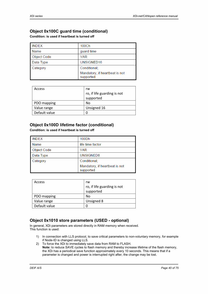
XDi series XDi-net/CANopen reference manual
DEIF A/S Page 40 of 75
Object 0x100C guard time (conditional) Condition: is used if heartbeat is turned off
Object 0x100D lifetime factor (conditional) Condition: is used if heartbeat is turned off
Object 0x1010 store parameters (USED - optional) In general, XDi parameters are stored directly in RAM memory when received. This function is used:
1) In connection with LLS protocol, to save critical parameters to non-voluntary memory, for example if Node-ID is changed using LLS.
2) To force the XDi to immediately save data from RAM to FLASH. Note: to reduce SAVE cycles to flash memory and thereby increase lifetime of the flash memory, the XDi has a periodical save function approximately every 10 seconds. This means that if a parameter is changed and power is interrupted right after, the change may be lost.
Access rw ro, if life guarding is not supported
PDO mapping No Value range Unsigned 16Default value 0
Access rw ro, if life guarding is not supported
PDO mapping No Value range Unsigned 8Default value 0

XDi series XDi-net/CANopen reference manual
DEIF A/S Page 41 of 75
SAVE function supported: READ the device storage functionality of the device by:
Bit sequence
SAVE command: the device to store parameters or data:
This is equal to ASCII: “Save”. Sub-index 0x00 Description Largest sub-index supportedEntry category MandatoryAccess ro PDO mapping No Value range 0x01-7FDefault value No Sub-index 0x01 Description Save all parametersEntry category MandatoryAccess rw PDO mapping No Value range Unsigned 32 (see r/w format
above) Default value No

XDi series XDi-net/CANopen reference manual
DEIF A/S Page 42 of 75
Object 0x1011 restore default parameters (USED - optional) This function is used to restore the factory settings; it is equal to making a manual master reset to factory settings.
RESTORE function supported: READ the device restore functionality from the device by:
XDi-net devices support the restore function, bit 0 = 1 . RESTORE command:
This is equal to ASCII: “Load”.
This is the XDi “Factory reset” command.
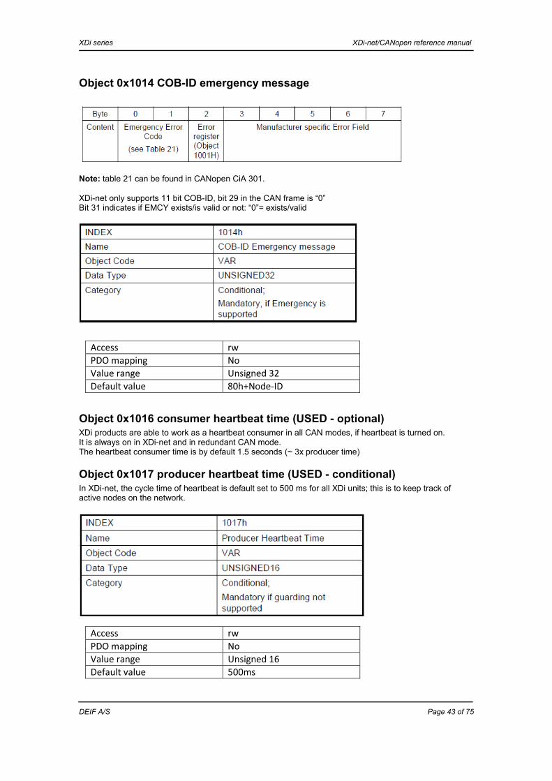
XDi series XDi-net/CANopen reference manual
DEIF A/S Page 43 of 75
Object 0x1014 COB-ID emergency message
Note: table 21 can be found in CANopen CiA 301. XDi-net only supports 11 bit COB-ID, bit 29 in the CAN frame is “0” Bit 31 indicates if EMCY exists/is valid or not: “0”= exists/valid
Object 0x1016 consumer heartbeat time (USED - optional) XDi products are able to work as a heartbeat consumer in all CAN modes, if heartbeat is turned on. It is always on in XDi-net and in redundant CAN mode. The heartbeat consumer time is by default 1.5 seconds (~ 3x producer time)
Object 0x1017 producer heartbeat time (USED - conditional) In XDi-net, the cycle time of heartbeat is default set to 500 ms for all XDi units; this is to keep track of active nodes on the network.
Access rw PDO mapping No Value range Unsigned 16Default value 500ms
Access rw PDO mapping No Value range Unsigned 32Default value 80h+Node-ID

XDi series XDi-net/CANopen reference manual
DEIF A/S Page 44 of 75
Object 0x1018 identity object (mandatory) The object at index 0x1018 contains general information about the XDi-net device. Sub-index 0x01: the vendor ID contains the unique manufacturer ID. Sub-index 0x02: the manufacturer-specific product code identifies a specific device version. Sub-index 0x03: the manufacturer-specific revision number consists of a major revision number and a minor revision number. The major revision number identifies a specific XDi-net/CANopen behaviour. If the XDi-net/CANopen functionality is expanded or changed significantly, so that it is no longer compatible with older versions, the major revision will be increased by one. The minor revision number identifies different versions with the same XDi-net/CANopen behaviour, those protocols are backward compatible, but may not include all functionality if interfacing with an XDi unit with an earlier minor revision. Sub-index 0x04: the manufacturer-specific serial number identifies a specific device.
Vendor ID
Sub-index 0x01Description Vendor ID Entry category MandatoryAccess ro PDO mapping No Value range Unsigned 32 Default value DEIF vendor ID

XDi series XDi-net/CANopen reference manual
DEIF A/S Page 45 of 75
The vendor ID consists of: 31 24 23 0
Department (DPM) Company (CompID) Vendor number and department number are both assigned by CiA. CANopen vendor ID (U24): CompID = 0x0000B2 DEIF Department (DPM) (U8): DPM=0x10 DEIF Bridge department - standard XDi-net products DPM=0x11 DEIF branded OEM Bridge product (typically a sensor) where DEIF CANopen vendor ID is implemented IMPORTANT: DEIF vendor ID and DPM = 0x10 may be used to identify an XDi unit from other types of CAN devices. All undefined DPM numbers are considered not valid.
Product code
Standard XDi-net product code format 31 24 23 16 15 8 7 0
Reserved Reserved Type (byte 1) Product (byte 0)
MSB LSB Defined product codes for DPM=0x10 Product type Product
(byte 0) Performance
type Type (byte 1)
Reserved 0x00 Single 0x00 XDi96 0x01 Dual 0x01 XDi144 0x02 Multi 0x02 XDi192 0x03 0x03 0x04 0x04 Note: For DPM=0x11, the OEM may have their own definition.
Sub-index 0x02Description Product code Entry category Used (optional) Access ro PDO mapping No Value range Unsigned 32 Default value No

XDi series XDi-net/CANopen reference manual
DEIF A/S Page 46 of 75
XDi-net revision number
Revision number structure
First major revision is 0x0001 Minor revision is 0x0001
Serial number
Serial number format The DEIF serial number consists of 6 digits + 4 digits. The first 6 digits are fixed for a manufacturing order of one or more XDi devices. The last 4 digits are the serial number within this manufacturing order, which starts from 0001 in each new order. To make the product serial number fit inside a 32-bit unsigned number, the first digit of the 4-digit serial number is removed and will not cause any problems, since the maximum order size is always less than 1000 XDi units. Example:
Full serial number
Short serial number
The “short serial number” is stored as an unsigned 32 bit value.
Sub-index 0X03Description XDi-net revision number Entry category Used (optional)Access ro PDO mapping No Value range Unsigned 32 Default value No
Sub-index 0x04Description Serial number Entry category Used (optional) Access ro PDO mapping No Value range Unsigned 32 Default value No
1 2 3 4 5 6 0 0 0 1
1 2 3 4 5 6 0 0 0 1
1 2 3 4 5 6 0 0 1

XDi series XDi-net/CANopen reference manual
DEIF A/S Page 47 of 75
Appendix 2 - data directory - XDi object index 0x2000-2FFF The 0x2000 section of the manufacturer-specific object index is used for system and main control parameters.
Object 0x2000 self-starting device (optional) Self-starting device is the ability to automatically enter operational state without an NMT command from a master. Timeout period in index 0x2000 sub 0x00 defines the time, in which an NMT “change state command” is expected. If the period expires without such a command, the XDi will automatically enter operational state. If the value of index 0x2000 sub-index 0x00 is set to zero, the device will stay in pre-operational mode and wait for an NMT command. Note: if the “XDi-net functions” or “Auto-start XDi on the CAN bus” is set to ON in the XDi CAN bus settings, this object has no effect and the device will go directly from pre-operational state to operational state. The default CAN settings are located in a product profile, and they can be changed from the CAN installation menu. Object description
Index 0x2000Name Self-starting device time periodObject code VAR*Data type Unsigned 16Category Optional
Entry description
Access rw PDO mapping NoDefault value 0x0001 (ms)Lower limit 0x0000Upper limit 0xFFFFUnit -

XDi series XDi-net/CANopen reference manual
DEIF A/S Page 48 of 75
Appendix 3 - XDi object index 0x3000-3FFF In the manufacturer-specified part of the CANopen object directory, the index sector from 0x3000 to 3FFF is called the “data directory” and is used to store and define the different variable input data types used by a virtual indicator. The sub-indexes are used to describe in details the data type, value, resolution and parameters directly related to this data type (for example critical bands related to the actual data type). The default setting of all used data types in an indicator are collected from the VI setup file. If setup parameters are changed via “Menu” or CAN, the corrected value is stored in the object index/sub-index and the sequence counter is increased by one.
Data type grouping/data type instance The data directory contains a large number of data types (for example “Propeller RPM”), and each data type contains a group of the same type of data, but with different instance. The group is called a “data type” with a reference index as header, and typically it consists of (additional) 15 indexes, all containing the same type of data but with a different instance. They are called “data type instances” (or just “data instances”), each defined by their “instance number” (i#). For example, the “Engine RPM” data type consists of a group of 16 indexes, where the first index 0x3200 (main index) contains general group information, and the rest represent RPM for engines 1 to 15, each assigned an RPM instance number (engine RPM-i#) . In the VI setup (VS) each indicator source is preset to use a fixed data type and instance, this cannot be changed from the menu. But it is possible to define several VI setups with different instances.
Location of data type at a given instance in the data object index table Data type number (main index) + instance number in the group, for example the index for RPM data from engine 5 is located in this object index: 0x3200+0x05= 0x3205. Note: it is only in case that there is more than one of the same data type on the CAN bus that it is necessary to use different instances to separate data.
Pre-defined variable data indexes XDi index
Max # objects
Instance
Object types Note
0x3000 – 0x3FFF
4096 Variable XDi input/output data
0x3000-0x31FF 512 Propulsion0x3000-0x300F 16 Azimuth & Rudder “-“ = bow turns to port 0x3010-0x301F 16 Rudder% “-“ = bow turns to port 0x3020-0x302F 16 Pitch angle “-“ = astern 0x3030-0x303F 16 Pitch% “-“ = astern 0x3040-0x307F 64 Reserved 0x3080-0x308F 16 Propeller RPM “-“ = astern 0x3090-0x309F 16 Propeller RPM% “-“ = astern 0x30A0-0x30AF 16 Propeller THRUST% “-“ = astern 0x30B0-0x30BF 16 Propeller POWER% “-“ = astern 0x30C0-0x30CF 16 Propeller LOAD%…… Reserved 0x3200-0x33FF 512 Engine data0x3200-0x320F 16 Engine RPM (eng. 1-15) “-“ = reverse, astern 0x3210-0x321F 16 Engine RPM% “-“ = reverse, astern

XDi series XDi-net/CANopen reference manual
DEIF A/S Page 49 of 75
XDi index
Max # objects
Instance
Object types Note
0x3220-0x322F 16 Engine THRUST% “-“ = reverse, astern 0x3230-0x323F 16 Engine POWER% “-“ = reverse, astern 0x3240-0x324F 16 Engine LOAD% “-“ = reverse, astern … 80 Reserved 0x32A0-0x32AF 16 Engine fuel consumption 0x32B0-0x32BF 16 Engine fuel consumption% … 64 Reserved 0x3300-0x330F 16 Pressure type 1 (eng. 1-15) 0x3310-0x331F 16 Pressure type 2 (eng. 1-15)…. 96 Reserved 0x3380-0x338F 16 Temperature type 1 (eng. 1-15)0x3390-0x339F 16 Temperature type 2 (eng. 1-15)…. Reserved 0x3400-0x34FF 256 Electrical 0x3400 - 340F 16 Electrical power AC10x3410 - 341F 16 Electrical power AC1%0x3420 - 342F 16 Electrical power AC20x3430 - 343F 16 Electrical power AC2%0x3440 - 345F 32 Reserved 0x3460 - 346F 16 Voltage AC10x3470 - 347F 16 Voltage AC20x3480 - 348F 16 Voltage DC0x3490 - 349F 16 Current AC10x34A0 – 34AF 16 Current AC20x34B0 – 34BF 16 Current DC0x34C0-0x34CF 16 Frequency A0x34D0-0x34DF
16 Frequency B
0x34E0-0x34EF 16 Insulation resistance AC0x34F0-0x34FF 16 Insulation resistance DC0x3500-0x351F 16 Dimmer 0x3500-0x350A 11 Dimmer group 1 to 9 (dimmer and
indicator day/night colour) 0x350B-0x351F - Reserved 0x3520-0x353F 32 Reserved 0x3540-0x354F 32 XDi-net “global” flags0x3540-0x354F 32 16 bit flag group (U16)0x3550-0x35FF 96 Reserved 0x3600-0x36FF Reserved 0x3700-0x37FF 256 Universal data (7 instance groups)0x3700-0x3707 8 Universal data group 0 (I16) Default resolution 0.1 0x3708-0x370F 8 Universal data group 1 (I16) Default resolution 0.1 0x3710-0x3717 8 Universal data group 2 (I16) Default resolution 0.1 0x3718-0x371F 8 Universal data group 3 (I16) Default resolution 0.1 0x3720-0x3727 8 Universal data group 4 (I16) Default resolution 1

XDi series XDi-net/CANopen reference manual
DEIF A/S Page 50 of 75
XDi index
Max # objects
Instance
Object types Note
0x3728-0x372F 8 Universal data group 5 (I16) Default resolution 1 0x3730-0x3737 8 Universal data group 6 (I16) Default resolution 1 0x3738-0x373F 8 Universal data group 7 (I16) Default resolution 1 0x3740-0x37FF 192 Reserved for “7 instance groups”0x3800-0x38FF 256 Reserved 0x3900-0x3AFF 512 Navigation data (TBD)0x3900-0x3907 8 Speed through water
(longitudinal) “-“ = reverse, astern and unit
is knot 0x3908-0x3AFF 504 Reserved for “7 instance groups”……. Reserved
Appendix 3.1 - general rules for XDi variable data and parameters Data specified in the XDi object directory as variable actual data (for example propeller RPM) is always located in sub-index 0x02, the fixed data resolution is located in sub-index 03 and it has a defined valid data range depending on the data type format (for example I16). If the data type also contains a set point value (commanded value), this value will be located in sub-index 0x07, and its resolution is stored in 0x08. The positive data range is limited to the max. positive value minus 2, and for “signed” data (integer) the largest negative signed value is limited to max. negative value plus one. For example, if the data type is using the full range of a 2 byte “I16” field, the valid value range is -32767 to +32765 [0x8000 (-32768) and 0x7FFE (32766) and 0x7FFF(32767) are reserved for error indication]. This applies to all variable data or parameters, if nothing else is specifically defined.
Indicator source data via CAN bus The virtual indicator in an XDi unit is collecting its input data from the pre-defined location in the object index table, where data is stored as an absolute (or %) value defined by the integer and a resolution defined for the data type. Example: propeller RPM1 at index 0x3081-02 contains the integer 1000, and the index 0x3081-03 contains the resolution value -1, this means that the absolute value to be indicated is: 1000x10-1 = 100 RPM. Note 1: the resolution is a fixed resolution pre-defined for each data type (for example propeller RPM) in the object index table. This table is stored in the XDi library and must be the same for all indicators that share data via the CAN bus network.

XDi series XDi-net/CANopen reference manual
DEIF A/S Page 51 of 75
Appendix 3.2 - input data structure in the XDi data directory All variable data is located in a “data type group” in the “data directory”. Data can either be an absolute data value or a relative % value. The “data directory” is located in index 0x3000 - 0x3FFF, and all data is stored following a standard index and sub-index structure. Each data type can have up to 15 instances (for example propeller RPM instance 1, 2, 3,…., 15), which identify several individual data sources delivering this type of data. Variable data broadcast on XDi-net or received via a DAM-MPDO is identified by its object index and sub-index. Actual data is sent in sub-index 0x02 and if it is a set point (commanded) value in sub-index 0x07.
Object index structure for all variable data types All XDi variable data types are defined as the examples in the table below for the azimuth angle data type.
Index Sub-index
Object description
Obj.
code
Da
ta ty
pe
Acc.
Defa
ult
valu
e
Cat.
M/O
Defa
ult C
OB-
ID/C
om. o
bj
Note
0x3000 Data group def. This describes the parameters for each instance in a data type carrying a value
0x00 Largest sub-index supported
U8 ro M -
0x01 Data type name Visible string 0-20 char.
ro See variable data list
M SDO The name of the data type defined by this 0x3xxx index group.
Ox02 Number of instances of this data type
U8 ro 0x0F M Ex-SDO
The number of instances is typically 15 (0x0F) that is instance 1 to 15 of the same type of data. For example azimuth 1 to azimuth 15.
Ox03 Variable data type and format
U8 ro 0x00 M Ex-SDO
The type of data stored in this data group: 0x00 Standard variable data actual and set
point, format I16 with resolution identifier.
0x01 Standard variable data actual and set point, format U16 with resolution identifier.
0xF0 Dimmer data type 1 0xF1 Source identifier
- Reserved 0x3001 Instance 1 of this data
type REC C
0x00 Largest sub-index supported
U8 ro 0x2F M -
0x01 Source name: {This is a menu, so the text in this field must be used as the menu text}
Visible string 0-20 char.
rw Az/Rd1
O SDO
Default name for this index for example “Rudder 1”. To be able to change this name is optional, but it is very useful to precisely identify the location of the device, for example “STBD Rudder 1”. The default name is located in the VI setup file.
0x02 Variable source data
I16 (U16)
rw 0x7FFF C XDi-net
The main data value of this data type is always located in sub-index 0x02, and it is used by an indicator as source data. Valid data range is indicated. For angle data

XDi series XDi-net/CANopen reference manual
DEIF A/S Page 52 of 75
Index Sub-index
Object description
Obj.
code
Da
ta ty
pe
Acc.
Defa
ult
valu
e
Cat.
M/O
Defa
ult C
OB-
ID/C
om. o
bj
Note
it may be: Range: -1800 – 0 – 1800 or 0xF8F8 – 0 – 0x0708 Out of range is defined: 0x8000 = Out of range “–“ (or 0xF8F7 - 0x8000) 0x7FFE = Out of range “+” (or 0x0709 - 0x7FFE) Additional information may be added: Positive value is STBD and negative is PORT. Error: 0x7FFF = is set according to general rules.
0x03 Data resolution (angle) I8
ro 0xFF O Ex-SDO
Indicates how data in sub-index is to be interpreted, A x 10r where [r] is the resolution parameter in this index Important: this is a fixed parameter for each data type in the data directory version used. 0xFD equals 0.001 0xFE equals 0.01 0xFF equals 0.1 0x00 equals 1 0x01 equals 10 0x02 equals 100 1x03 equals 1000 (See CiA 303 for details) Example: if the value in sub-index 02 = 2000 and resolution = 0xFF (r = -1) then the data value is 2000x10-1 equal to 200.0 0x7E restricted 0x7F = data is full 16 bit range (I16) (not restricted).
0x04 Data unit (angle in degrees) Not supported - reserved
U8 ro 0x41 O SDO Data unit notation index, the standard codes for data units can be found in CiA 303. This is a fixed unit for the data directory and cannot be changed. In this case: 0x41 = Degree This is not used in the present XDi release.
0x05 Change sequence number SEQ#
U16 rw 0x0000 M XDi-net Ex-SDO
Standard change identification is described elsewhere in this document.
0x06 Set point source name:
Visiblestring 0-20 char
rw Az/Rd1 TBD
O SDO
Default name for the set point for this data type, for example “Rudder 1 command”. See source name for more details.
0x07 SET POINT value I16 (U16)
rw 0x7FFF O XDi-net
The set point value for the data type. (Data unit is the same as main data).
0x08 SET POINT I8 ro 0xFF O Ex- Same format as for actual data value 0x02.

XDi series XDi-net/CANopen reference manual
DEIF A/S Page 53 of 75
Index Sub-index
Object description
Obj.
code
Da
ta ty
pe
Acc.
Defa
ult
valu
e
Cat.
M/O
Defa
ult C
OB-
ID/C
om. o
bj
Note
Data resolution SDO Typically it is the same resolution as the actual source value.
0x09 Actual data presentation flag
U8 rw 0x01 Ex-SDO
Flag that indicates the presentation status of the data type. 0x00 = Hide actual data of this type 0x01 = Present actual data of this type 0x02...0xFF reserved
0x0A Set point data presentation flag
U8 rw 0x01 O Ex-SDO
Flag that indicates the presentation status of the data type. 0x00 = Hide actual data of this type 0x01 = Present actual data of this type 0x02...0xFF reserved
….. Reserved Critical band 1 Used for sector marking on indicator 0x10 Critical band 1 High:
{Pair1}
I16 rw 0x7FFF O Ex-SDO
Value referred to is sub-index 0x02 range 0x7FFF = Band is not used.
0x11 Critical band 1 Low: {Pair1}
I16 rw 0x7FFF O Ex-SDO
Value referred to is sub-index 0x02 range 0x7FFF = Band is not used.
0x12 Band 1 text: Visible string 0-20 char.
rw Band 1 O SDO
0x13 Band 1 text control flag U8 rw - O Ex-SDO
0x14 Band 1 pointer colour select
U8 rw - O Ex-SDO
Defines pointer colour, when within band. 0x00 = Normal 0x01 = Alert 0x02 = Warning
…. Reserved (band 1) Critical band 2 Used for sector marking on indicator 0x18 Critical band 2 High:
{Pair1}
I16 rw 0x7FFF O Ex-SDO
Value referred to is sub-index 0x02 range 0x7FFF = Band is not used.
0x19 Critical band 2 Low: {Pair1}
I16 rw 0x7FFF O Ex-SDO
Value referred to is sub-index 0x02 range 0x7FFF = Band is not used.
0x1A Band 2 text: Visible string 0-20 char.
Band 2 O Ex-SDO
0x1B Band 2 text control flag U8 rw O Ex-SDO
0x1C Band 2 pointer colour select
U8 rw - O Ex-SDO
Defines pointer colour, when within band. 0x00 = Normal 0x01 = Alert 0x02 = Warning
…. Reserved (band 2) Critical band 3 Used for sector marking on indicator 0x20 Critical band 3 High:
{Pair3}
I16 rw 0x7FFF O Ex-SDO
Value referred to is sub-index 0x02 range 0x7FFF = Band is not used.
0x21 Critical band 3 Low:
I16 rw 0x7FFF O Ex-SDO
Value referred to is sub-index 0x02 range 0x7FFF = Band is not used.

XDi series XDi-net/CANopen reference manual
DEIF A/S Page 54 of 75
Index Sub-index
Object description
Obj.
code
Da
ta ty
pe
Acc.
Defa
ult
valu
e
Cat.
M/O
Defa
ult C
OB-
ID/C
om. o
bj
Note
{Pair3} 0x22 Band 3 text: Visible
string 0-20 char.
Band 3 O Ex-SDO
0x23 Band 3 text control flag U8 rw O Ex-SDO
0x24 Band 3 pointer colour select
U8 rw - O Ex-SDO
Defines pointer colour, when within band. 0x00 = Normal 0x01 = Alert 0x02 = Warning
…. Reserved (band 3) Critical band 4 Used for sector marking on indicator 0x28 Critical band 4 High:
{Pair3}
I16 rw 0x7FFF O Ex-SDO
Value referred to is sub-index 0x02 range 0x7FFF = Band is not used.
0x29 Critical band 4 Low: {Pair4}
I16 rw 0x7FFF O Ex-SDO
Value referred to is sub-index 0x02 range 0x7FFF = Band is not used.
0x2A Band 4 text: Visible string 0-20 char
Band 4 O Ex-SDO
0x2B Band 4 text control flag U8 rw O Ex-SDO
0x2C Band 4 pointer colour select
U8 rw - O Ex-SDO
Defines pointer colour, when within band. 0x00 = Normal 0x01 = Alert 0x02 = Warning
…. Reserved (band 4) 0x22 Reserved ….. Reserved More instances of this
data type Note: the structure is the same for all
instances of the data type. 0x3002 Instance 2
of this data type REC Same as 0x3001 default XDi-net
0x3003 Instance 3 of this data type
REC Same as 0x3001 default XDi-net
……. 0x300F Instance 15
of this data type REC Same as 0x3001 default XDi-net
Note: critical band is only working if the virtual indicator is designed with functions that utilise this function. For example red sectors on an RPM indicator.

XDi series XDi-net/CANopen reference manual
DEIF A/S Page 55 of 75
Object index structure for dimmer groups Each dimmer group has a set of parameters. The most important for control via CAN is the actual dimmer level, sub-index 0x02 and the actual colour pallet 0x03 (if colour is not automatically controlled from the dimmer level).
Index Sub-index
Object description
Obj.
code
Da
ta ty
pe
Acc.
Defa
ult
valu
e
Cat.
M/O
.
Defa
ult
COB-
ID/
Com
. obj
.
Note
0x3500 Dimmer general definition
See index 0x3000 above for data type heading specification.
0x3501 Dimmer and colour pallet group 1
REC System wide setup, all units using this dimmer group will store this setup and keep it updated if changes are made.
0x00 Largest sub-index supported
U8 ro M -
0x01 Dimmer group name (short name)
Text string max. 20 char.
rw DimGr.1 M SDO Max. 20 characters
0x02 Actual dimmer level U8 rw TBD M XDi-net (MPDO) (TPFO)
The dimmer level set for the group. Valid range 0-100 equal to 0 to 100 % backlight. For example controlled by the analogue input.
0x03 Actual colour pallet U8 rw / ro
00 O XDi-net Ex-SDO
Bit 0,1: 00 = Day 01 = Night 10 = Dusk 11 = Reserved (illegal value) Bits 2-7 are reserved (Don’t care) Read only if auto pallet shift is active. If library only contains day/night pallet, then bit 1 must be ignored.
0x04 Change sequence number SEQ#
U32 rw 0x0000 M XDi-net Ex-SDO
See detailed description of SEQ# and synch. process in this document.
0x05 Default dimmer start-up and menu level
U8 rw 50 O XDi-net Ex-SDO
Default value at power-up (in %). Also used as minimum menu level. Local setting.
0x06 Dimmer colour pallet mode
U8 rw 0 O XDi-net Ex-SDO
0x00 = Separate dim and colour 0x01 = Auto day/night 0x02 = Auto day/dusk/night >0x02 = Reserved
0x07 Pallet shift level low Day or dusk to night
U8 rw 30 O XDi-net Ex-SDO
Shift between: Mode 1: day and night (mode 1). Mode 2: dusk and night (mode 2). Shift to night at this input dimmer %. If shift is 0xFF function is inhibit.
0x08 Pallet shift level high Day to dusk
U8 rw 70 O XDi-net Ex-SDO
Only mode 2. Shift between day and dusk. Shift from day to dusk at this input dimmer %. If shift is 0xFF function is inhibit.
0x09 Colour shift hysteresis %
U8 rw 0x01 O XDi-net Ex-SDO
Hysteresis before dimmer makes a change, when going from a higher value to a lower value.

XDi series XDi-net/CANopen reference manual
DEIF A/S Page 56 of 75
Index Sub-index
Object description
Obj.
code
Da
ta ty
pe
Acc.
Defa
ult
valu
e
Cat.
M/O
.
Defa
ult
COB-
ID/
Com
. obj
.
Note
0 = No hysteresis, every step is used. 1 = 1 % change before shift. 2 = 2 % change before shift. 10 = 10 % change before shift.
0x0A Day min. backlight level U8 rw 0x00 O XDi-net Ex-SDO
Sets the backlight level to a new min. level at the point where the colour pallet is just about to shift from day to dusk or night pallet. (Separate description is available).
0x0B Dusk max. backlight level
U8 rw 0x00 O XDi-net Ex-SDO
Raises the backlight level to a new max. level when the colour pallet has just shifted from day to dusk pallet. (Separate description is available).
0x0C Dusk min. backlight level
U8 rw 0x00 O XDi-net Ex-SDO
Sets the backlight level to a new min. level at the point where the colour pallet has just shifted from night to dusk pallet.
0x0D Night max. backlight level
U8 rw 0x00 O XDi-net Ex-SDO
Raises the backlight level to a new max. level at the point where the colour pallet is about to shift from night to dusk or day pallet.
0x0E Min. global backlight offset level
U8 rw 0x00 O XDi-net Ex-SDO
Lowest backlight level that equals lowest allowed dimming level. Backlight level offset range 0-50. Global setting.
0x3502 Dimmer and colour pallet group 2
REC System wide setup, all units using this dimmer group will store this setup.
0x3503 Dimmer and colour pallet group 3
REC System wide setup, all units using this dimmer group will store this setup.
0x3504 Dimmer and colour pallet group 4
REC System wide setup, all units using this dimmer group will store this setup.
0x3505 Dimmer and colour pallet group 5
REC System wide setup, all units using this dimmer group will store this setup.
0x3506 Dimmer and colour pallet group 6
REC System wide setup, all units using this dimmer group will store this setup.
0x3507 Dimmer and colour pallet group 7
REC System wide setup, all units using this dimmer group will store this setup.
0x3508 Dimmer and colour pallet group 8
REC System wide setup, all units using this dimmer group will store this setup.
0x3509 Dimmer and colour pallet group 9
REC System wide setup, all units using this dimmer group will store this setup.
0x350A Dimmer and colour pallet group 0 (LOCAL)
REC System wide setup, all units using this dimmer group will store this setup.

XDi series XDi-net/CANopen reference manual
DEIF A/S Page 57 of 75
Appendix 4 - index 0x4000-4FFF product parameters Product setup and status data is stored in this sector of the manufacturer-specific index. Data in this section is individually set for each XDi unit in a CAN system and is therefore not synchronised by broadcast throughout the network.
0x4000 - 0x48FF
2304 Product and product profile Note
0x4000 1 Product ID and profile type 0x4001 1 Installed XDi library and data
directory
0x4002 1 Virtual indicator and VI setup selection
0x4003 1 Product profile parameters 0x4004 1 Dimmer and colour pallet 0x4005 1 HW options 0x4006 1 SW options 0x4007 1 Library setup select
…. 0x400A-401F 21 Product data Product setup, for example warnings,
sound, HW monitor data… ….. 225 Reserved
0x4100-42FF 512 Virtual indicator setup 0x4100 1 Reserved (headline header)
0x4101-410F 15 Headline lists Selectable headlines (menu or CAN) 0x4110 1 Reserved (label header)
0x4111-412F 31 Label lists Selectable headlines (menu or CAN) 0x4130 1 Reserved (units header)
0x4131-414F 31 Unit lists Selectable headlines (menu or CAN) 0x4150 1 Reserved (scale header)
0x4151-416F 31 Scale values Local CAN programmable values used locally in the selected VI indicator
…. 0x4200 1 Reserved (source header)
0x4201-0x423F 63 Source list Selectable indicator data source list …. Reserved

XDi series XDi-net/CANopen reference manual
DEIF A/S Page 58 of 75
Object index list 0x4000-0x40FF
Index Sub-index
Object description
Obj.
code
Da
ta ty
pe
Acc.
Defa
ult
valu
e
Cat.
M/O
.
Defa
ult C
OB-
ID/
Com
m.
Note Read-only data is copied from the XDi library loaded into the XDi-net product
0x4000 to 0x401F
Product profile for this XDi Node
Virtual indicator setup and XDi product profile data
0x4000 Product prof., library and VI setup
REC
0x00 Largest sub-index supported
U8 ro M Ex-SDO
0x01 Product Node-ID no. U8 ro 0x01 M Ex-SDO The Node-ID of the XDi units that contain this XDi object index.
0x02 Product profile type U16 ro 0x0000 M Ex-SDO 0x0000 = XDi standard profile. If this has another value, the product profile section 0x4001-0x4xxx does not follow the description below. There will be another unique description. Valid range: 0x0000-0xFFFE 0xFFFF = Reserved
0x03 Hardware configuration U16 ro 0x0000 M Ex-SDO 0x0000 = Basis configuration. 0x0001-0x0FFF reserved for DEIF HW config. 0x1000 to 0x1FFF = Customer HW configuration. 0x2000 and up is reserved.
0x04 Product ID U16 ro 0 M Ex-SDO Used for product identification and reference for logged reliability data in the product. Valid range: 10.001-11.000 (0x2711-2AF8) 0 for undefined.
0x05 Product S/N String ro - M SDO Used for product identification. … Reserved 0x11 Platform SW version U32 ro - C Ex-SDO Software version X.YZ.V (for example
1.23.4) represented in decimal XYZV (for example 1234) represented as hex value in the U32 format (for example 0x0000 04D2).
0x21 QT application SW version
U32 ro - C Ex-SDO Same
0x31 Console application SW version
U32 ro - C Ex-SDO Same
0x4001 Installed XDi library REC 0x00 Largest sub-index
supported U8 ro M Ex-SDO
0x01 Reserved
0x02 LIB owner ID number U32 ro - M Ex-SDO Range: 0-4294967294 0xFFFFFFFF = Reserved
0x03 LIB number U32 ro - M Ex-SDO Lib. number is allocated to each LIB owner. Range: 1-4294967294 Value 0x0…00 indicates that no LIB is loaded.
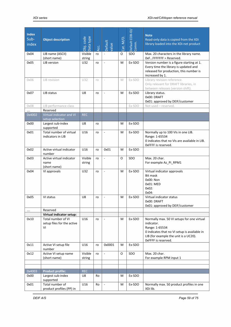
XDi series XDi-net/CANopen reference manual
DEIF A/S Page 59 of 75
Index Sub-index
Object description
Obj.
code
Da
ta ty
pe
Acc.
Defa
ult
valu
e
Cat.
M/O
.
Defa
ult C
OB-
ID/
Com
m.
Note Read-only data is copied from the XDi library loaded into the XDi-net product
0x04 LIB name (ASCII) (short name)
Visible string
ro - O SDO Max. 20 characters in the library name. 0xF…FFFFFFF = Reserved.
0x05 LIB version U32 ro - M Ex-SDO Version number is a figure starting at 1. Every time the library is updated and released for production, this number is increased by 1.
0x06 LIB revision U32 ro - M Ex-SDO Library revision reference. Only relevant for DRAFT libraries, in between releases (version shift).
0x07 LIB status U8 ro - M Ex-SDO Library status. 0x00: DRAFT 0x01: approved by DEIF/customer
0x08 LIB performance class Ex-SDO Not used – reserved. …. Reserved 0x4002 Virtual indicator and VI
setup selection REC
0x00 Largest sub-index supported
U8 ro M Ex-SDO
0x01 Total number of virtual indicators in LIB
U16 ro - M Ex-SDO Normally up to 100 VIs in one LIB. Range: 1-65534 0 indicates that no VIs are available in LIB. 0xFFFF is reserved.
0x02 Active virtual indicator number
U16 ro 0x01 M Ex-SDO
0x03 Active virtual indicator name (short name)
Visible string
ro - O SDO Max. 20 char. For example Az_Pi_RPM1
0x04 VI approvals U32 ro - M Ex-SDO Virtual indicator approvals Bit mask 0x00: Non 0x01: MED 0x02: 0x04:
0x05 VI status U8 ro - M Ex-SDO Virtual indicator status 0x00: DRAFT 0x01: approved by DEIF/customer
…. Reserved Virtual indicator setup: 0x10 Total number of VI
setup files for the active VI
U16 ro - M Ex-SDO Normally max. 50 VI setups for one virtual indicator. Range: 1-65534 0 indicates that no VI setup is available in LIB (for example the unit is a UC20). 0xFFFF is reserved.
0x11 Active VI setup file number
U16 ro 0x0001 M Ex-SDO
0x12 Active VI setup name (short name)
Visible string
ro - O SDO Max. 20 char. For example RPM input 1
0x4003 Product profile: REC 0x00 Largest sub-index
supported U8 Ro M Ex-SDO
0x01 Total number of product profiles (PP) in
U16 Ro - M Ex-SDO Normally max. 50 product profiles in one XDi lib.

XDi series XDi-net/CANopen reference manual
DEIF A/S Page 60 of 75
Index Sub-index
Object description
Obj.
code
Da
ta ty
pe
Acc.
Defa
ult
valu
e
Cat.
M/O
.
Defa
ult C
OB-
ID/
Com
m.
Note Read-only data is copied from the XDi library loaded into the XDi-net product
this LIB Range: 1-65534 0 indicates that no PP is available in LIB. 0xFFFF is reserved.
0x02 Active PP file number U16 ro 0x0001 M Ex-SDO 0x03 Active product profile
name (short name)
Visible string
ro - O SDO Max. 20 char. For example PP17_Dim1_AutoColor
0x4004 Dimmer and colour
pallet REC
0x00 Largest sub-index supported
U8 ro M Ex-SDO
0x01 Selected dimmer group for this unit (Node-ID)
U8 rw 0x01 M Ex-SDO The dimmer group that this unit is assigned to follow. (Dimmer group settings are in 0x3500) Dimmer group 0x00 is local – no dimming via network 0x01 Group 1 0x02 Group 2 …. 0x08 Group 8 0x09 Group 9 0x0A to 0xFE is reserved (set to 0) 0xFF = Reserved
0x02 Dimmer source for this unit (Node-ID)
U8 rw 0x02 M Ex-SDO The active dimmer source for this unit: 0x00 = Digital option module 0x01 = Analogue option module 0x02 = XDi-net 0x03 = DAMPDO (controlled by CAN master) 0x04 = PDO converter (RPDO/TPDO input) 0x05 = Front buttons 0x06 = Front buttons and digital option (both) 0x07…0xFF reserved
0x03 Colour select source for this unit (Node-ID)
U8 rw 0x02 M Ex-SDO The active colour select source for this unit: 0x00 = Non – fixed colour 0x01 = Digital option module 0x02 = XDi-net 0x03 = DAMPDO (controlled by CAN master) 0x04 = PDO converter (RPDO/TPDO input) 0x05 = Front buttons 0x06 = Front buttons and digital option (both) 0x07…0xFF reserved
0x04 Min. local backlight level
U8 rw 0 O Ex-SDO Lowest backlight level that equals 0 % dimming input. Backlight level offset range 0-100. Local setting for the unit.
0x05 Max. local backlight level. Dimmer 100 % calibration
U8 rw 250 O Ex-SDO Parameter to adjust backlight setting to be equal to other XDi units (for example new/ old), local setting for the actual unit – not

XDi series XDi-net/CANopen reference manual
DEIF A/S Page 61 of 75
Index Sub-index
Object description
Obj.
code
Da
ta ty
pe
Acc.
Defa
ult
valu
e
Cat.
M/O
.
Defa
ult C
OB-
ID/
Com
m.
Note Read-only data is copied from the XDi library loaded into the XDi-net product
shared on CAN bus. Backlight level (scaled) = 0 to 250 Valid range for this parameter is 50 to 250. 255 = Not available or valid.
0x4005 HW options 0x00 Largest sub-index
supported U8 ro M Ex-SDO
0x01 Option type slot 1 U32 ro - C Ex-SDO TYPE: Byte 0: 0x00 = No module 0x01 = DX1 (digital module) 0x02 = AX1 (analogue module) 0x03 = NX 1 (serial data module) 0x04 = NX 2 (serial data module) >0x04 = Reserved for new modules 0xFF = Slot is not available in product. Bytes 1-3 are reserved.
… Reserved 0x11 Option type slot 2 U32 ro - C Ex-SDO Same as above for slot 1. …. Reserved 0x4006 SW options 0x00 Largest sub-index
supported U8 ro M Ex-SDO
0x4007 OD status handling 0x00 Largest sub-index
supported U8 ro M Ex-SDO
0x01 Select indicator and setup
U32 wo
- C Ex-SDO Setup PP (product profile), VI (virtual indicator) and VS (virtual indicator setup). Byte 0: VS 1-255 Bytes 1-2: VI 1-65535 Byte 3: PP 1-255 Value will be set to command status when the command has been executed (after less than 30 seconds). Command status: 0xFFFFFFFF: ERROR 0x00000000: idle (new setup has been executed). 0xXXYYYYZZ: setup not changed (XX = old VS, YYYY = old VI, ZZ = old PP. The XDi already has this setup).
0x4008 Reserved …… Reserved 0x400A Product warning setup 0x00 Largest sub-index
supported U8 ro M Ex-SDO
0x01 CAN1 bus error warning ON/OFF
U8 rw 0x01 M Ex-SDO 0x00 = OFF 0x01 = ON Rest is reserved.

XDi series XDi-net/CANopen reference manual
DEIF A/S Page 62 of 75
Index Sub-index
Object description
Obj.
code
Da
ta ty
pe
Acc.
Defa
ult
valu
e
Cat.
M/O
.
Defa
ult C
OB-
ID/
Com
m.
Note Read-only data is copied from the XDi library loaded into the XDi-net product
0x02 CAN2 bus error warning ON/OFF
U8 rw 0x01 M Ex-SDO 0x00 = OFF 0x01 = ON Rest is reserved.
0x03 Supply voltage 1 monitor ON/OFF
U8 rw 0x01 M Ex-SDO 0x00 = OFF 0x01 = ON Rest is reserved.
0x04 Supply voltage 2 monitor ON/OFF
U8 rw 0x01 M Ex-SDO 0x00 = OFF 0x01 = ON Rest is reserved.
0x05 Data lost warning pop-up ON/OFF
U8 rw 0x01 M Ex-SDO 0x00 = OFF 0x01 = ON Rest is reserved.
0x06 Parameter error ON/OFF
U8 rw 0x01 M Ex-SDO 0x00 = OFF 0x01 = ON Rest is reserved.
0x400B Product sound and display setup
0x00 Largest sub-index supported
U8 ro M Ex-SDO
0x01 Beep on key press ON/OFF
U8 rw 0x01 M Ex-SDO 0x00 = OFF 0x01 = ON Rest is reserved.
0x02 Acoustic warnings ON/OFF
U8 rw 0x01 M Ex-SDO 0x00 = OFF 0x01 = ON Rest is reserved.
0x03 Acoustic alerts ON/OFF U8 rw 0x01 M Ex-SDO 0x00 = OFF 0x01 = ON Rest is reserved.
0x04 Display rotation Normal/upside down
U8 rw 0x00 M Ex-SDO 0x00 = Normal 0x01 = Upside down (rotated 180 deg.) Rest is reserved.
…. 0x401F SDO write protection 0x00 Largest sub-index
supported U8 ro 0x02 M Ex-SDO
0x01 Lock/unlock of SDO write
U32 rw 0x80000000
M Ex-SDO 0x7FFFFFFF: normal unlocked SDO (write) operation. 0x80000000: all manufacturer-specific profile parameters (0x2000…0x5FFF) are blocked for SDO (write) operations (except the SDO protection object index itself).
0x02 SDO write protection timeout
U16 rw 5000 M Ex-SDO 0: no timeout on SDO (write) operation. SDO (write) operation is only controlled from sub-index 0x01. >0: timeout in [ms]. When time, since last successful SDO (write), exceeds timeout, force sub-index 0x01 value to 0x80000000. Value between 1…999 is forced to 1000, to ensure that timeout is never lower than 1000 [ms].
….. Reserved 0x40FF Reserved

XDi series XDi-net/CANopen reference manual
DEIF A/S Page 63 of 75
XDi directory 0x4100-0x42FF definitions (virtual indicator setup)
Definition of text lists for virtual indicators 0x4100 to 0x414F This object index section is used to store “text lists” of the following types: headline, label and unit. For each list, sub-index 0x01 to 0x10 contains parameters that describe the text list. The number of fixed text lines is limited to max. 32 lines (sub-index 0x11 to 0x30), and the number of empty lines in which new text lines may be entered via menu or via CAN bus is also limited to 32 lines (0x31 to 0x50). A text list is only active if it is designed into the selected virtual indicator and pre-defined in the relevant VI setup profile. Note: adding or changing this type of text lines either via menu or via CAN will only affect the selected indicator and will not be shared globally.
Index Sub-index
Object description
Obj.
code
Da
ta ty
pe
Acc.
Defa
ult
valu
e
Cat.
M/O
.
Defa
ult C
OB-
ID/
Com
m.
Note Read-only data is copied from the XDi library loaded into the XDi-net product
0x4100 Data type “Headline list” definition
0x00 Largest sub-index supported
U8 ro 0x2F M -
0x01 Text label type name Visible string 0-20 char.
ro Head-lines
M SDO The name of the data type defined by this 0x4xxx index group.
0x02 Number of instances of this data type
U8 ro 0x0F M The reserved number of instances of this type is default 15 (0x0F). Note: instance in 0x4000 is not the same as for variable data in the 0x3000 area.
0x03 Data type and format U8 ro 0x90 M The type of data stored in this object type. See 0x3000 0x90 text lines
- Reserved 0x4101 Headline list 1 for the
selected indicator REC Is used to present a headline from a pre-
defined list of headlines. List and content is defined in the VI setup
0x00 Largest sub-index supported
U8 ro 0xXX M -
0x01 Selected text line sub- index (TXTL)
U8 rw 0x00 M Ex-SDO
The text is located in sub-index no. = 0x11 – 0x50 => TXTL Valid range 0x11 to 0x50. The line number must be validated when selected via menu. External CAN controller must validate this, if this sub-index has an invalid value the text line must be empty. If TXTL value is 0x00, the headline must be presented as empty (invisible).
0x02 Max. number of characters allowed in the text line
U8 ro 32 M Ex-SDO
The number of characters may be limited by the indicator design, in that case this value is less than 32 and indicates the max. number of characters.
0x03
Number of fixed text lines
U8 ro 01 M Ex-SDO
This number indicates the number of available pre-defined text lines ( cannot be

XDi series XDi-net/CANopen reference manual
DEIF A/S Page 64 of 75
Index Sub-index
Object description
Obj.
code
Da
ta ty
pe
Acc.
Defa
ult
valu
e
Cat.
M/O
.
Defa
ult C
OB-
ID/
Com
m.
Note Read-only data is copied from the XDi library loaded into the XDi-net product
(FTL) changed – read-only). Fixed lines always start from 0x11 and upwards, new lines entered via menu are located after the last fixed line.
0x04
Number of new text lines (NTL)
U8 rw 01 O Ex-SDO
This number indicates how many text lines that have been added as “new or editable text”.
….. Reserved 0x11 Fixed text line 1 Visible
string 0-32 char.
ro - CM
SDO
Contains the text to be used as the first text line in the menu list and, if selected, presented on the virtual indicator as the headline. May be read as one string using normal SDO transfer.
0x12 Fixed text line 2 Visible string 0-32 char.
ro - CM
SDO
Contains the text to be used as the 2nd text line in the menu list and, if selected, presented on the virtual indicator as the headline. May be read as one string using normal SDO transfer.
…. 0x30 Fixed text line 32 0x31 New text line 1 Visible
string 0-32 char.
rw - CM
SDO
Contains the text to be used as the text line in the menu list and, if selected, presented on the virtual indicator as the headline. May be transferred (read/write) as one string using normal SDO transfer. If the string is not yet used but is available for use, it may contain an empty text string, defined by “” (should not be presented then for menu selection). It is allowed to add or delete the content of this type of string, by menu or CAN.
….. 0x50 New text line 32 Last text line defined. 0x4102 Headline list 2 REC …. 0x410F Headline list 15 REC 0x4110 Data type “Label list”
definition
0x00 Largest sub-index supported
U8 ro 0x03 M -
0x01 Text label type name Visible string 0-20 char.
ro Labels M SDO The name of the data type defined by this 0x4xxx index group.
0x02 Number of instances of this data type
U8 ro 0x1F M The reserved number of instances of this type is default 31 (0x1F). Note: instance in 0x4000 is not the same as for variable data in the 0x3000 area.
0x03 Data type and format U8 ro 0x90 M The type of data stored in this object type. See 0x3000 0x90 text lines

XDi series XDi-net/CANopen reference manual
DEIF A/S Page 65 of 75
Index Sub-index
Object description
Obj.
code
Da
ta ty
pe
Acc.
Defa
ult
valu
e
Cat.
M/O
.
Defa
ult C
OB-
ID/
Com
m.
Note Read-only data is copied from the XDi library loaded into the XDi-net product
0x4111 Label list 1 for the
selected indicator REC Is used to present a headline from a pre-
defined list of headlines. List and content is defined in the VI setup
0x00… Same format as for 0x4101
Same definition as for 0x4101, but labels instead of headlines.
0x4112 Label list 2 REC …. 0x412F Label list 31 REC 0x4130 Data type “Unit list”
definition
0x00 Largest sub-index supported
U8 ro 0x03 M -
0x01 Text label type name Visible string 0-20 char.
ro Units M SDO The name of the data type defined by this 0x4xxx index group.
0x02 Number of instances of this data type
U8 ro 0x1F M The reserved number of instances of this type is default 31 (0x1F). Note: instance in 0x4000 is not the same as for variable data in the 0x3000 area.
0x03 Data type and format U8 ro 0x90 M The type of data stored in this object type. See 0x3000 0x90 text lines
0x4131 Label 1 for the selected indicator
REC Is used to present a headline from a pre-defined list of headlines. List and content is defined in the VI setup
0x00… Same format as for 0x4101
Same definition as for 0x4101, but labels instead of headlines.
0x4132 Unit list 2 REC …. 0x414F Unit list 31 REC
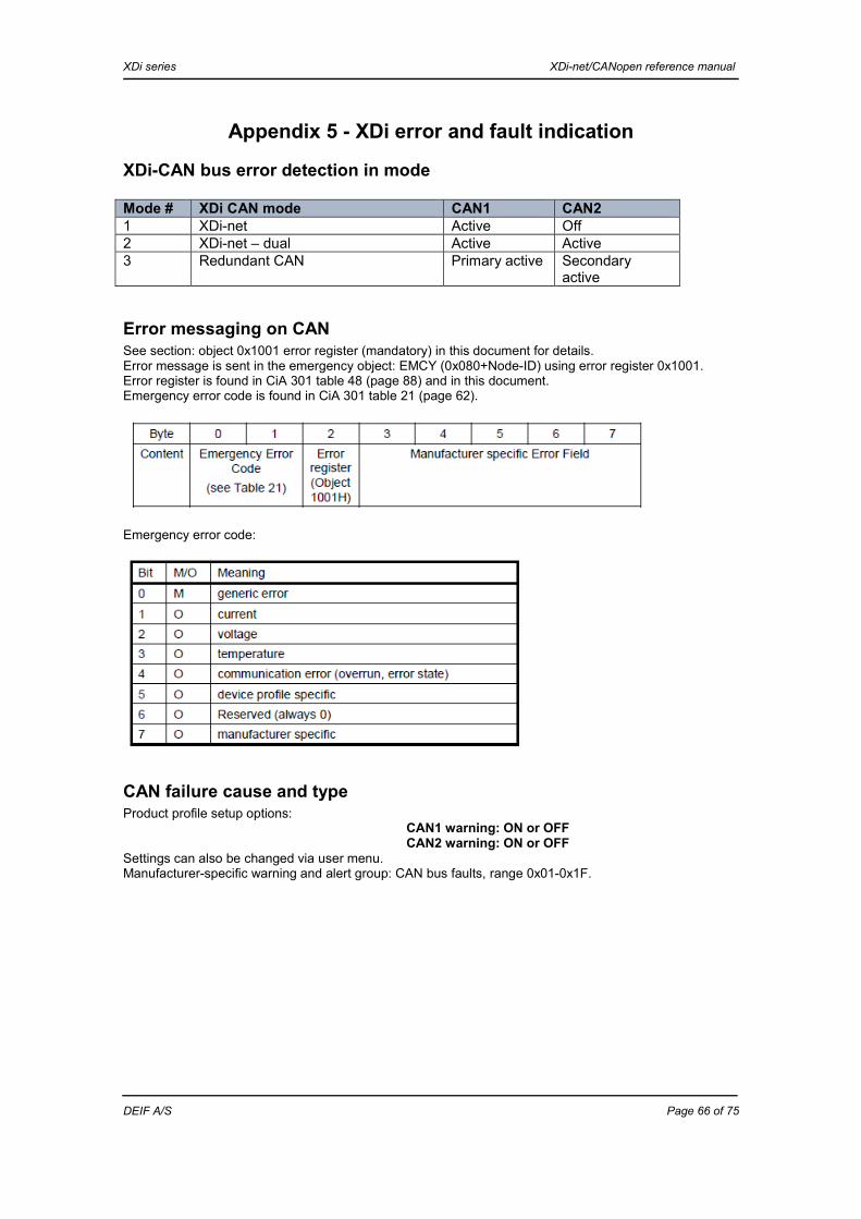
XDi series XDi-net/CANopen reference manual
DEIF A/S Page 66 of 75
Appendix 5 - XDi error and fault indication
XDi-CAN bus error detection in mode Mode # XDi CAN mode CAN1 CAN21 XDi-net Active Off 2 XDi-net – dual Active Active 3 Redundant CAN Primary active Secondary
active
Error messaging on CAN See section: object 0x1001 error register (mandatory) in this document for details. Error message is sent in the emergency object: EMCY (0x080+Node-ID) using error register 0x1001. Error register is found in CiA 301 table 48 (page 88) and in this document. Emergency error code is found in CiA 301 table 21 (page 62).
Emergency error code:
CAN failure cause and type Product profile setup options:
CAN1 warning: ON or OFF CAN2 warning: ON or OFF
Settings can also be changed via user menu. Manufacturer-specific warning and alert group: CAN bus faults, range 0x01-0x1F.
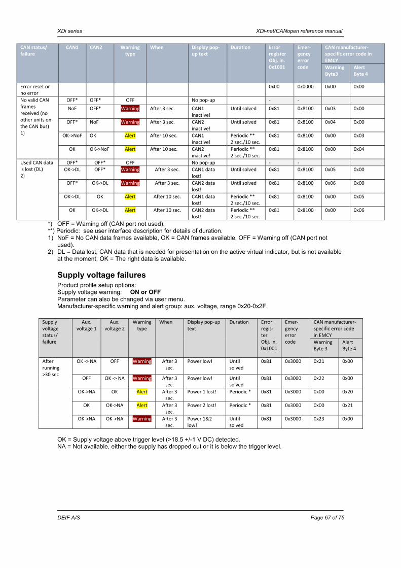
XDi series XDi-net/CANopen reference manual
DEIF A/S Page 67 of 75
*) OFF = Warning off (CAN port not used). **) Periodic: see user interface description for details of duration. 1) NoF = No CAN data frames available, OK = CAN frames available, OFF = Warning off (CAN port not
used). 2) DL = Data lost, CAN data that is needed for presentation on the active virtual indicator, but is not available
at the moment, OK = The right data is available.
Supply voltage failures Product profile setup options: Supply voltage warning: ON or OFF Parameter can also be changed via user menu. Manufacturer-specific warning and alert group: aux. voltage, range 0x20-0x2F.
OK = Supply voltage above trigger level (>18.5 +/-1 V DC) detected. NA = Not available, either the supply has dropped out or it is below the trigger level.
CAN status/ failure
CAN1 CAN2 Warning type
When Display pop-up text
Duration
Error register Obj. in. 0x1001
Emer-gency error code
CAN manufacturer-specific error code in EMCY WarningByte3
AlertByte 4
Error reset or no error
0x00 0x0000 0x00 0x00
No valid CAN frames received (no other units on the CAN bus) 1)
OFF* OFF* OFF No pop-up - - NoF OFF* Warning After 3 sec. CAN1
inactive! Until solved 0x81 0x8100 0x03 0x00
OFF* NoF Warning After 3 sec. CAN2 inactive!
Until solved 0x81 0x8100 0x04 0x00
OK->NoF
OK Alert After 10 sec. CAN1 inactive!
Periodic ** 2 sec./10 sec.
0x81 0x8100 0x00 0x03
OK OK->NoF Alert After 10 sec. CAN2 inactive!
Periodic ** 2 sec./10 sec.
0x81 0x8100 0x00 0x04
Used CAN data is lost (DL) 2)
OFF* OFF* OFF No pop-up - - OK->DL OFF* Warning After 3 sec. CAN1 data
lost! Until solved 0x81 0x8100 0x05 0x00
OFF* OK->DL Warning After 3 sec. CAN2 data lost!
Until solved 0x81 0x8100 0x06 0x00
OK->DL
OK Alert After 10 sec. CAN1 data lost!
Periodic ** 2 sec./10 sec.
0x81 0x8100 0x00 0x05
OK
OK->DL Alert After 10 sec. CAN2 data lost!
Periodic ** 2 sec./10 sec.
0x81 0x8100 0x00 0x06
Supply voltage status/ failure
Aux. voltage 1
Aux. voltage 2
Warning type
When Display pop-up text
Duration
Error regis-ter Obj. in. 0x1001
Emer-gency error code
CAN manufacturer-specific error code in EMCY Warning Byte 3
AlertByte 4
After running >30 sec
OK -> NA OFF Warning After 3 sec.
Power low! Until solved
0x81 0x3000 0x21 0x00
OFF
OK -> NA Warning After 3 sec.
Power low! Until solved
0x81 0x3000 0x22 0x00
OK->NA OK Alert After 3 sec.
Power 1 lost! Periodic * 0x81 0x3000 0x00 0x20
OK OK->NA Alert After 3 sec.
Power 2 lost! Periodic * 0x81 0x3000 0x00 0x21
OK->NA OK->NA Warning After 3 sec.
Power 1&2 low!
Until solved
0x81 0x3000 0x23 0x00

XDi series XDi-net/CANopen reference manual
DEIF A/S Page 68 of 75
Appendix 6 - MPDO parameter settings The following appendix describes the correct settings of the communication parameters for MPDOs.
General CANopen header parameter settings
Bit 31: 0 = PDO exists Bit 30: 1 = No RTR allowed on this PDO Bit 29: 0 = 11-bit ID
SAM-MPDO communication parameter settings (index 0x1400-0x1403) Used for XDi-net broadcast communication.
Index Sub-index
Object description
Obj.
code
Da
ta ty
pe
Acc.
Defa
ult
valu
e
Cat.
M/O
.
Defa
ult C
OB-
ID/C
om. o
bj.
Note
0x1400
Receive PDO parameter (setup for XDi-net)
PDO comm.Par.
M
0x00 Largest sub-index supp. U8 ro 0x02 M Ex-SDO
0x01 COB-ID used by PDO U32 ro 0x27F M Ex-SDO
(Fixed in XDi-net)
0x02 Transmission type U8 ro 254 M Ex-SDO
Manufacturer-specific part of dir.
0x03 Inhibit time U16 rw Not used
O - Not used by XDi-net
0x04 Compatibility entry U8 rw Not used
O Not used by XDi-net
0x05 Event timer U16 rw 0x0000 = Not used
O Not used

XDi series XDi-net/CANopen reference manual
DEIF A/S Page 69 of 75
SAM-MPDO mapping parameter settings (index 0x1600-0x17FF)
Index Sub-index
Object description
Obj.
code
Da
ta ty
pe
Acc.
Defa
ult
valu
e
Cat.
M/O
.
Defa
ult C
OB-
ID/C
om. o
bj.
Note
0x1600 Receive PDO1 mapping (set up as MPDO)
Rec M
0x00 Number of mapped application objects in PDO
U8 ro 0xFE M Ex-SDO
0xFE indicates that it is an MPDO in SAM (source address mode)
DAM-MPDO settings When an XDi unit is set up to accept DAM-MPDO input communication to the XDi-net object index directly from a CAN master or controller, one of the four default RPDOs is used for this. The following shows the setup of RPDO2 as DAM-MPDO for an XDi unit, followed by a table giving the overview of how to set up all XDi-related RPDOs as multiplexed PDOs. RPDO1 settings for use as DAM-MPDO2 with access to the XDi object index area. Bit 31: 0 = PDO exists Bit 30: 1 = No RTR allowed on this PDO Bit 29: 0 = 11-bit ID
DAM-MPDO communication parameter settings (index 0x1400-0x1403)
Index Sub-index
Object description
Obj.
code
Da
ta ty
pe
Acc.
Defa
ult
valu
e
Cat.
M/O
.
Defa
ult C
OB-
ID/C
om. o
bj.
Note
0x1401
Receive PDO1 parameter (set up as MPDO)
PDO Comm. Par.
M
0x00 Largest sub-index supp. U8 ro 0x02 M Ex-SDO
0x01 COB-ID used by PDO U32 ro 0x200+Node-ID
M Ex-SDO
0x02 Transmission type U8 ro 254 M Ex-SDO
Manufacturer-specific part of dir.
0x03 Inhibit time U16 rw Not used
O - Not used by XDi-net.
0x04 Compatibility entry U8 rw Not used
O Not used by XDi-net.
0x05 Event timer U16 rw 0x0000 = Not used
O Set to “Not used” in XDi-net. Data transmissions depend on data type, and parameter change is only sent when they are changed.
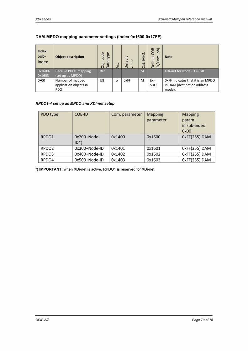
XDi series XDi-net/CANopen reference manual
DEIF A/S Page 70 of 75
DAM-MPDO mapping parameter settings (index 0x1600-0x17FF)
Index Sub-index
Object description
Obj.
code
Da
ta ty
pe
Acc.
Defa
ult
valu
e
Cat.
M/O
.
Defa
ult C
OB-
ID/C
om. o
bj.
Note
0x1600-0x1603
Receive PDO1 mapping (set up as MPDO)
Rec M XDi-net for Node-ID = 0x01
0x00 Number of mapped application objects in PDO
U8 ro 0xFF M Ex-SDO
0xFF indicates that it is an MPDO in DAM (destination address mode).
RPDO1-4 set up as MPDO and XDi-net setup
PDO type COB-ID Com. parameter Mapping parameter
Mapping param. in sub-index 0x00
RPDO1 0x200+Node-ID*)
0x1400 0x1600 0xFF(255) DAM
RPDO2 0x300+Node-ID 0x1401 0x1601 0xFF(255) DAMRPDO3 0x400+Node-ID 0x1402 0x1602 0xFF(255) DAMRPDO4 0x500+Node-ID 0x1403 0x1603 0xFF(255) DAM
*) IMPORTANT: when XDi-net is active, RPDO1 is reserved for XDi-net.
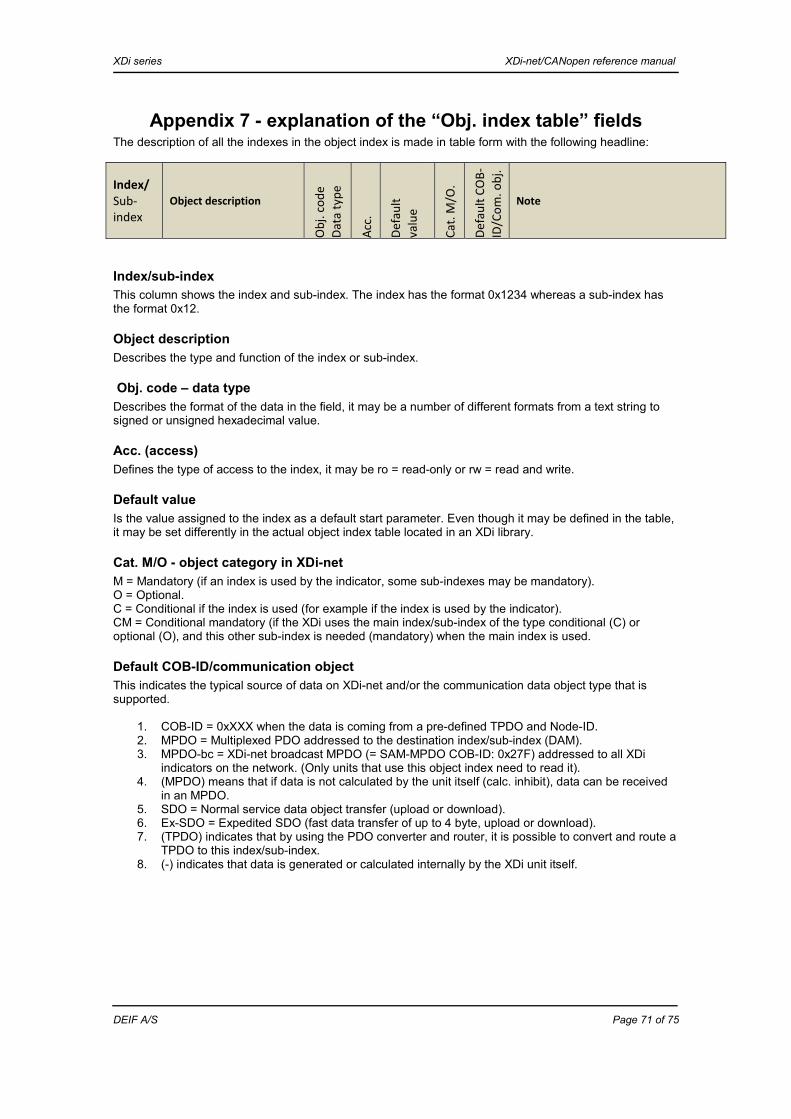
XDi series XDi-net/CANopen reference manual
DEIF A/S Page 71 of 75
Appendix 7 - explanation of the “Obj. index table” fields The description of all the indexes in the object index is made in table form with the following headline:
Index/ Sub-index
Object description
Obj.
code
Da
ta ty
pe
Acc.
Defa
ult
valu
e
Cat.
M/O
.
Defa
ult C
OB-
ID/C
om. o
bj.
Note
Index/sub-index This column shows the index and sub-index. The index has the format 0x1234 whereas a sub-index has the format 0x12.
Object description Describes the type and function of the index or sub-index.
Obj. code – data type Describes the format of the data in the field, it may be a number of different formats from a text string to signed or unsigned hexadecimal value.
Acc. (access) Defines the type of access to the index, it may be ro = read-only or rw = read and write.
Default value Is the value assigned to the index as a default start parameter. Even though it may be defined in the table, it may be set differently in the actual object index table located in an XDi library.
Cat. M/O - object category in XDi-net M = Mandatory (if an index is used by the indicator, some sub-indexes may be mandatory). O = Optional. C = Conditional if the index is used (for example if the index is used by the indicator). CM = Conditional mandatory (if the XDi uses the main index/sub-index of the type conditional (C) or optional (O), and this other sub-index is needed (mandatory) when the main index is used.
Default COB-ID/communication object This indicates the typical source of data on XDi-net and/or the communication data object type that is supported.
1. COB-ID = 0xXXX when the data is coming from a pre-defined TPDO and Node-ID. 2. MPDO = Multiplexed PDO addressed to the destination index/sub-index (DAM). 3. MPDO-bc = XDi-net broadcast MPDO (= SAM-MPDO COB-ID: 0x27F) addressed to all XDi
indicators on the network. (Only units that use this object index need to read it). 4. (MPDO) means that if data is not calculated by the unit itself (calc. inhibit), data can be received
in an MPDO. 5. SDO = Normal service data object transfer (upload or download). 6. Ex-SDO = Expedited SDO (fast data transfer of up to 4 byte, upload or download). 7. (TPDO) indicates that by using the PDO converter and router, it is possible to convert and route a
TPDO to this index/sub-index. 8. (-) indicates that data is generated or calculated internally by the XDi unit itself.

XDi series XDi-net/CANopen reference manual
DEIF A/S Page 72 of 75
Appendix 8 - EDS file description
Introduction CANopen is designed for a system controlled by a central master, to which data of all sensors is sent, and the master will then distribute the data to all consumers that need the data. Most systems that use XDi are built without a master, and data is distributed directly from the sensor (or controller) to the data consumer (indicator). The EDS file structure is made for the master-based system, and therefore direct data routing without a master is not included in the EDS. The available EDS file for XDi is a generic type, which can be used to read and write the general CANopen parameters as described in the following. The generic EDS can be downloaded from: http://www.deif.com/software/software-download or it can be sent by email on request. The library-specific input parameters must be handled manually or in combination with the general XDi EDS file. The definition of all library-specific CAN parameters, for example CAN input for virtual indicators, are all found in the specification document that is made for each DEIF standard or customised XDi library.
EDS file - object index content CANopen defines the first part of the object index from 0x1000 to 0x1FFF. The second part from 0x2000 to 0x5FFF is the manufacturer-specific part of the CANopen object index table. You can find the detailed description in the relevant sections of this document.
CANopen defined object indexes, 0x1000 group 0x1000 Device type 0x1001 Error register 0x1002 Manufacturer status register 0x1008 Manufacturer device name 0x100A Manufacturer software version 0x100C Guard time 0x100D Lifetime factor 0x1010 Store parameter field 0x1011 Restore default parameters 0x1014 COB-ID emergency object 0x1016 Heartbeat consumer entries 0x1017 Producer heartbeat time 0x1018 Identity object See Appendix 1 for details.
PDO parameters The following parameters define the PDOs that will be used by the XDi itself for receiving or transmitting data. The default settings in the generic EDS may be different in a customised library, and they may also change dependent on active virtual indicator/VI setup. It may therefore be necessary to adjust the EDS manually to fit the actual indicator and system.
Receive PDOs 0x1400 Receive PDO communication parameter 1 0x1401 Receive PDO communication parameter 2 0x1402 Receive PDO communication parameter 3 0x1403 Receive PDO communication parameter 4 0x1600 Receive PDO mapping parameter 1 0x1601 Receive PDO mapping parameter 2 0x1602 Receive PDO mapping parameter 3 0x1603 Receive PDO mapping parameter 4

XDi series XDi-net/CANopen reference manual
DEIF A/S Page 73 of 75
The generic EDS is set up to define RPDO1 for XDi-net communication using SAM-MPDO, and RPDO2-4 are defined as DAM-MPDOs. XDi-net is using the CANopen source address mode - multiplexed PDO communication format – SAM MPDO to broadcast data using the manufacturer-specific object index directory. Index 0x1400-02 is set up for transmission type 0xFE (asynchronous, manufacturer-specified object index), and 0x1600-00 is set up for 0xFE (254), that means SAM-MPDO operation.
RPDO 2 to 4 are pre-defined for DAM-MPDO, also using manufacturer-specific object index directory. This function is default off, but it can be activated in a customised “product profile” (PP), or it can be activated manually on the XDi from the CAN setup menu. XDi supports one RPDO in DAM-MPDO mode. If you want to use that, it must either be activated in the PP in your custom XDi indicator library, or you will have to activate it via menu. (Ask DEIF product management if you want to use RPDO1 for other applications than XDi-net).
Transmit PDOs The XDi is by default not transmitting any TPDOs, it has to be defined in the VI setup for the active virtual indicator. 0x1800 Transmit PDO communication parameter 1 0x1801 Transmit PDO communication parameter 2 0x1802 Transmit PDO communication parameter 3 0x1803 Transmit PDO communication parameter 4 0x1A00 Transmit PDO mapping parameter 1 0x1A01 Transmit PDO mapping parameter 2 0x1A02 Transmit PDO mapping parameter 3 0x1A03 Transmit PDO mapping parameter 4 By default, 0x1800 to1803 are set up to transmission type 0xFE (asynchronous, manufacturer-specified object index) and 0x1A00 to 1A03 are set up as deactivated. If the virtual indicator is set up to share data in a TPDO, the correct parameter settings should be manually added to the EDS file, if needed in the CAN tool used for setup.
Redundancy configuration parameters The two CAN ports on the XDi can be set up for redundant CAN operation. The below index is only relevant when this function is activated. 0x1F60 Redundancy configuration parameters For more details use: “CiA 307 Technical Report Proposal - Framework for maritime electronics”, where redundant system for marine applications and related parameters are described.
From CiA 301:
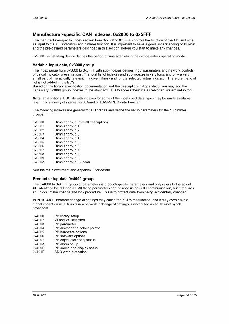
XDi series XDi-net/CANopen reference manual
DEIF A/S Page 74 of 75
Manufacturer-specific CAN indexes, 0x2000 to 0x5FFF The manufacturer-specific index section from 0x2000 to 0x5FFF controls the function of the XDi and acts as input to the XDi indicators and dimmer function. It is important to have a good understanding of XDi-net and the pre-defined parameters described in this section, before you start to make any changes. 0x2000: self-starting device defines the period of time after which the device enters operating mode.
Variable input data, 0x3000 group The index range from 0x3000 to 0x3FFF with sub-indexes defines input parameters and network controls of virtual indicator presentations. The total list of indexes and sub-indexes is very long, and only a very small part of it is actually relevant in a given library and for the selected virtual indicator. Therefore the total list is not added in the EDS. Based on the library specification documentation and the description in Appendix 3, you may add the necessary 0x3000 group indexes to the standard EDS to access them via a CANopen system setup tool. Note: an additional EDS file with indexes for some of the most used data types may be made available later, this is mainly of interest for XDi-net or DAM-MPDO data transfer. The following indexes are general for all libraries and define the setup parameters for the 10 dimmer groups: 0x3500 Dimmer group (overall description) 0x3501 Dimmer group 1 0x3502 Dimmer group 2 0x3503 Dimmer group 3 0x3504 Dimmer group 4 0x3505 Dimmer group 5 0x3506 Dimmer group 6 0x3507 Dimmer group 7 0x3508 Dimmer group 8 0x3509 Dimmer group 9 0x350A Dimmer group 0 (local) See the main document and Appendix 3 for details.
Product setup data 0x4000 group The 0x4000 to 0x4FFF group of parameters is product-specific parameters and only refers to the actual XDi identified by its Node-ID. All these parameters can be read using SDO communication, but it requires an unlock, make change and lock procedure. This is to protect data from being accidentally changed. IMPORTANT: incorrect change of settings may cause the XDi to malfunction, and it may even have a global impact on all XDi units in a network if change of settings is distributed as an XDi-net synch. broadcast. 0x4000 PP library setup 0x4002 VI and VS selection 0x4003 PP parameter 0x4004 PP dimmer and colour palette 0x4005 PP hardware options 0x4006 PP software options 0x4007 PP object dictionary status 0x400A PP alarm setup 0x400B PP sound and display setup 0x401F SDO write protection

XDi series XDi-net/CANopen reference manual
DEIF A/S Page 75 of 75
Headline lists The following indexes are only used, if one or more headlines are available in the selected virtual indicator: Selectable headline lists, one list is used for each headline on a virtual indicator: 0x4100 VS headline list group (header for the group) 0x4101 VS headline list 1 0x4102 VS headline list 2 0x4103 VS headline list 3 0x4104 VS headline list 4 0x4105 VS headline list 5 One index list is used for each headline that is used in a virtual indicator design. Labels and units use a similar format, but since it has not been used in any library yet, it is not included in the present generic EDS file. If you require an updated generic EDS, contact DEIF product management.