WHITE PAPER - Nexenta€¦ · WHITE PAPER NexentaStorTM: ZFS File System Features, ... Databases...
13
WHITE PAPER NexentaStor TM : ZFS File System Features, Technical Overview
Transcript of WHITE PAPER - Nexenta€¦ · WHITE PAPER NexentaStorTM: ZFS File System Features, ... Databases...

WHITE PAPER
NexentaStorTM: ZFS File System Features, Technical Overview
Copyright © 2014 Nexenta All Rights Reserved
2
Table of Contents
Overview ....................................................................................................................................................... 3
ZFS Hybrid Storage Pool (HSP) ...................................................................................................................... 4
Adaptive Replacement Cache (ARC) ....................................................................................................... 4
Level-Two ARC (L2ARC) .......................................................................................................................... 4
ZFS Intent Log (ZIL) ................................................................................................................................. 4
Hard Disk Drives (HDD) ........................................................................................................................... 5
New Storage Parameter: Working Set Size (WSS) .................................................................................. 5
Conclusion: Hybrid Storage Pools........................................................................................................... 5
ZFS Copy on Write (COW) ............................................................................................................................. 6
ZFS Never Modifies Data in Place ........................................................................................................... 6
ZFS Checksums ....................................................................................................................................... 7
ZFS Always Consistent on Disk ............................................................................................................... 8
ZFS Snapshots ............................................................................................................................................. 10
ZFS Replication ............................................................................................................................................ 11
ZFS Resilvering ............................................................................................................................................ 12
Creating a New RAID Set ...................................................................................................................... 12
Recovering from a Transient Outage ................................................................................................... 12
Replacing a Failed Drive ....................................................................................................................... 13
Nexenta is a registered trademark of Nexenta Systems Inc., in the United States and other countries. All other trademarks, service marks and company names mentioned in this document are properties of their respective owners. © 2014 Nexenta

Copyright © 2014 Nexenta All Rights Reserved
3
Overview
The Nexenta HA Cluster consists of NexentaStor™ appliances running a defined set of services and
monitoring each other for failures. It enables two NexentaStor instances to be configured as an active / active pair. Neither system is designated specifically as primary or secondary. Both systems can be actively managing shared storage, although volumes are owned by only one system at any given time.
When installed and configured, each instance of NexentaStor is able to perform all functions. At the same time, along with another NexentaStor instance, the licensed feature provides high availability for shared storage accessible from both appliances.
Volume services can be migrated between cluster appliances either manually or automatically upon failure of one appliance.
NexentaStor HA Cluster management can be configured via both Nexenta Management Console (NMC) and the appliance’s Web GUI (NMV).
Storage is jointly managed via the HA Cluster and is configured as shared storage. RAID and replication policies can be established to protect data in a number of ways with the aid of NexentaStor.
Copyright © 2014 Nexenta All Rights Reserved
4
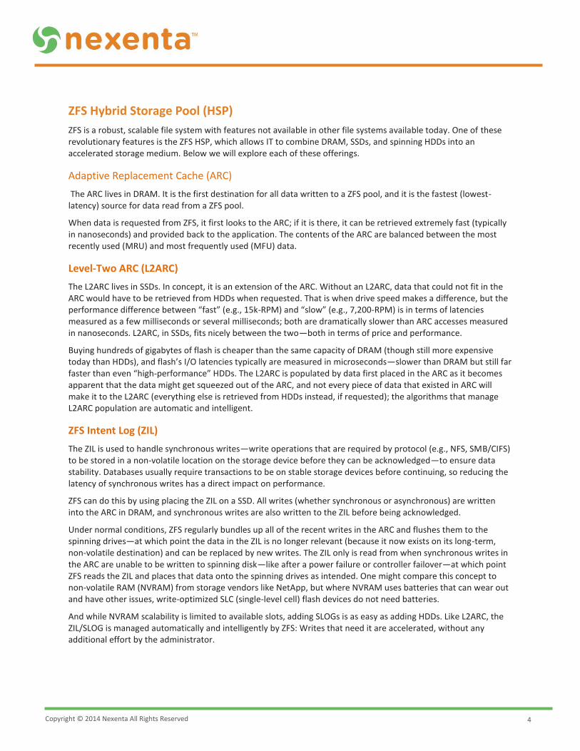
ZFS Hybrid Storage Pool (HSP)
ZFS is a robust, scalable file system with features not available in other file systems available today. One of these revolutionary features is the ZFS HSP, which allows IT to combine DRAM, SSDs, and spinning HDDs into an accelerated storage medium. Below we will explore each of these offerings.
Adaptive Replacement Cache (ARC)
The ARC lives in DRAM. It is the first destination for all data written to a ZFS pool, and it is the fastest (lowest-latency) source for data read from a ZFS pool.
When data is requested from ZFS, it first looks to the ARC; if it is there, it can be retrieved extremely fast (typically in nanoseconds) and provided back to the application. The contents of the ARC are balanced between the most recently used (MRU) and most frequently used (MFU) data.
Level-Two ARC (L2ARC)
The L2ARC lives in SSDs. In concept, it is an extension of the ARC. Without an L2ARC, data that could not fit in the ARC would have to be retrieved from HDDs when requested. That is when drive speed makes a difference, but the performance difference between “fast” (e.g., 15k-RPM) and “slow” (e.g., 7,200-RPM) is in terms of latencies measured as a few milliseconds or several milliseconds; both are dramatically slower than ARC accesses measured in nanoseconds. L2ARC, in SSDs, fits nicely between the two—both in terms of price and performance.
Buying hundreds of gigabytes of flash is cheaper than the same capacity of DRAM (though still more expensive today than HDDs), and flash’s I/O latencies typically are measured in microseconds—slower than DRAM but still far faster than even “high-performance” HDDs. The L2ARC is populated by data first placed in the ARC as it becomes apparent that the data might get squeezed out of the ARC, and not every piece of data that existed in ARC will make it to the L2ARC (everything else is retrieved from HDDs instead, if requested); the algorithms that manage L2ARC population are automatic and intelligent.
ZFS Intent Log (ZIL)
The ZIL is used to handle synchronous writes—write operations that are required by protocol (e.g., NFS, SMB/CIFS) to be stored in a non-volatile location on the storage device before they can be acknowledged—to ensure data stability. Databases usually require transactions to be on stable storage devices before continuing, so reducing the latency of synchronous writes has a direct impact on performance.
ZFS can do this by using placing the ZIL on a SSD. All writes (whether synchronous or asynchronous) are written into the ARC in DRAM, and synchronous writes are also written to the ZIL before being acknowledged.
Under normal conditions, ZFS regularly bundles up all of the recent writes in the ARC and flushes them to the spinning drives—at which point the data in the ZIL is no longer relevant (because it now exists on its long-term, non-volatile destination) and can be replaced by new writes. The ZIL only is read from when synchronous writes in the ARC are unable to be written to spinning disk—like after a power failure or controller failover—at which point ZFS reads the ZIL and places that data onto the spinning drives as intended. One might compare this concept to non-volatile RAM (NVRAM) from storage vendors like NetApp, but where NVRAM uses batteries that can wear out and have other issues, write-optimized SLC (single-level cell) flash devices do not need batteries.
And while NVRAM scalability is limited to available slots, adding SLOGs is as easy as adding HDDs. Like L2ARC, the ZIL/SLOG is managed automatically and intelligently by ZFS: Writes that need it are accelerated, without any additional effort by the administrator.

Copyright © 2014 Nexenta All Rights Reserved
5
Hard Disk Drives (HDD)
With the ARC, L2ARC, and ZIL/SLOG providing the bulk of the performance from a ZFS Hybrid Storage Pool, spinning drives are relegated to the job they do well—providing lower-performance, higher-density, low-cost storage capacity. Until the day that flash competes with HDDs on a dollar-per-gigabyte front, the right balance of DRAM and flash for performance, and HDDs for capacity, results in a total cost of ownership (TCO) that is less—both initially and over the long-term—than solving both requirements using all flash or all HDDs.
New Storage Parameter: Working Set Size (WSS)
For legacy storage systems, sizing means determining necessary capacity, IOPS, and throughput and then performing some simple math to determine the number of spindles that could provide those numbers.
As the industry moves towards more sophisticated caching methodologies in storage systems, a new parameter for expressing storage needs has become evident: The WSS can be described as the subset of total data that is actively worked upon (e.g., 500GB of this quarter’s sales data out of a total database of 20TB).
Knowing the WSS makes it possible to size ARC, L2ARC, and even HDDs more accurately, but few applications today have an awareness of WSS.
Conclusion: Hybrid Storage Pools
ZFS hybrid storage pools intelligently combine DRAM, flash, and hard disk drives to achieve the right balance of cost and performance for any given working set, while reducing the need for administrators to constantly monitor storage for I/O bottlenecks.
By reducing both read and write latency with the use of flash in a ZFS hybrid storage pool, we end up with a system that performs far better than legacy storage systems, while having a much lower total cost of ownership (TCO).
Copyright © 2014 Nexenta All Rights Reserved
6
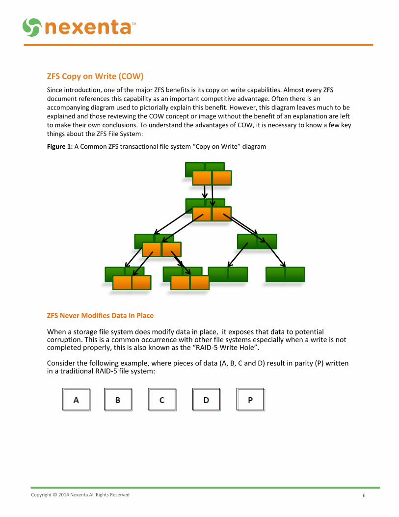
ZFS Copy on Write (COW)
Since introduction, one of the major ZFS benefits is its copy on write capabilities. Almost every ZFS document references this capability as an important competitive advantage. Often there is an accompanying diagram used to pictorially explain this benefit. However, this diagram leaves much to be explained and those reviewing the COW concept or image without the benefit of an explanation are left to make their own conclusions. To understand the advantages of COW, it is necessary to know a few key things about the ZFS File System:
Figure 1: A Common ZFS transactional file system “Copy on Write” diagram
ZFS Never Modifies Data in Place When a storage file system does modify data in place, it exposes that data to potential corruption. This is a common occurrence with other file systems especially when a write is not completed properly, this is also known as the “RAID-5 Write Hole”. Consider the following example, where pieces of data (A, B, C and D) result in parity (P) written in a traditional RAID-5 file system:

Copyright © 2014 Nexenta All Rights Reserved
7
If (A) is to be modified to (A’) the parity must be recalculated to (P’) and updated as well—as shown below:
However, should the storage file system get interrupted between the modification of (A) to (A’) and (P) to (P’), it is possible to end up with the following situation—where (P) is the old and incorrect parity value for (A’), (B), (C) and (D). Now this is corrupted data! The traditional RAID-5 file system is unaware of the problem. In fact, most traditional file systems blindly trust parity data. This problem may go undetected for a long period of time, but if (P) is ever called upon to reconstruct a drive that contains (A’), it would result in entirely incorrect data in the file system. By never modifying data in place, ZFS avoids this problem.
ZFS Checksums
ZFS File System Checksums are stored with the parent and are present in every data and metadata block. Whereas, traditional file systems store a data block’s checksum physically next to the data. If the checksum algorithm is strong (and not all file systems use a strong checksum algorithm), reading the checksum and comparing it to the data will detect an error within the data block (often called bit rot or digital decay).
This does not, however, protect against several other very real problems—things like phantom writes (where a drive claimed to have written data but never did), misdirected reads or writes (where a drive read or wrote a data block with a matching checksum but in the wrong location), and other problems (like drive firmware bugs).
However, ZFS can detect all these conditions and correct them in mirrored or RAIDZ configurations! ZFS has this ability because the checksums for each data and metadata block are stored in physically separate locations with pointer information from “parent” to “child”—often depicted as a tree as in the following diagram.
These checksums are calculated and compared every time ZFS walks through this tree to retrieve a piece of data, and if data is found to be in error, ZFS will use parity to return the correct data. It then goes ahead and fixes any bad data blocks as well! Note that even the highest parent metadata block is itself protected by a checksum stored in an “uberblock” (the entry point of a ZFS file system)—of which there are multiple copies stored in strategic places on disk.
Copyright © 2014 Nexenta All Rights Reserved
8
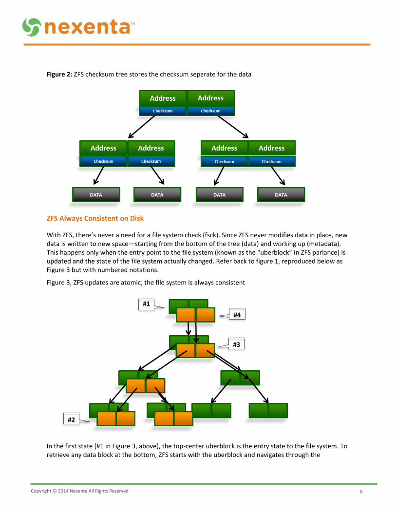
Figure 2: ZFS checksum tree stores the checksum separate for the data
ZFS Always Consistent on Disk
With ZFS, there’s never a need for a file system check (fsck). Since ZFS never modifies data in place, new data is written to new space—starting from the bottom of the tree (data) and working up (metadata). This happens only when the entry point to the file system (known as the “uberblock” in ZFS parlance) is updated and the state of the file system actually changed. Refer back to figure 1, reproduced below as Figure 3 but with numbered notations.
Figure 3, ZFS updates are atomic; the file system is always consistent
In the first state (#1 in Figure 3, above), the top-center uberblock is the entry state to the file system. To retrieve any data block at the bottom, ZFS starts with the uberblock and navigates through the
#1
#2
#4
#3
Copyright © 2014 Nexenta All Rights Reserved
9
appropriate metadata block pointers (comparing checksums along the way) to retrieve the appropriate data and be sure of its integrity.
In the next state (#2, above), the process of modifying the bottom-left two data blocks has begun. The green blocks depict the new data written in a new place, but that means that new parent block pointers, with checksums for the new data, are required as well.
In the third state (#3, above), most of the necessary new metadata block pointers have been written, but the uberblock has not yet been updated. Note that the orange state of the file system still is perfectly consistent, because all metadata and data is still intact. In the event of a power loss at this point, the storage system could still navigate the orange file system state without error after the system restarts.
Finally (step #4, above), the uberblock is updated in what is known as an “atomic” operation—meaning it either happens successfully or it does not happen at all. At this point, the new state of the file system—containing all of the green blocks and the unchanged orange blocks from the right-hand side—also is perfectly consistent and updated with the new bottom-left data. Note that ZFS moves from one perfectly consistent file system state to another. The old orange data and metadata blocks are then freed for future use.
The 4 step process just described is also known as “copy on write”. There are times when multiple parent block pointers can refer to a single physical block of data on disk. This poses no problem for ZFS; when a user of this data needs to modify it, the new data is written to a new place and all the necessary metadata changes are made (this is also known as “redirect on write”.
Note: Not all the updates depicted in the diagrams above are necessarily writes to disk; many of these updates happen simultaneously when ZFS flushes its transaction groups from memory to disk. In addition, there are numerous optimizations not described above.
Copyright © 2014 Nexenta All Rights Reserved
10
ZFS Snapshots
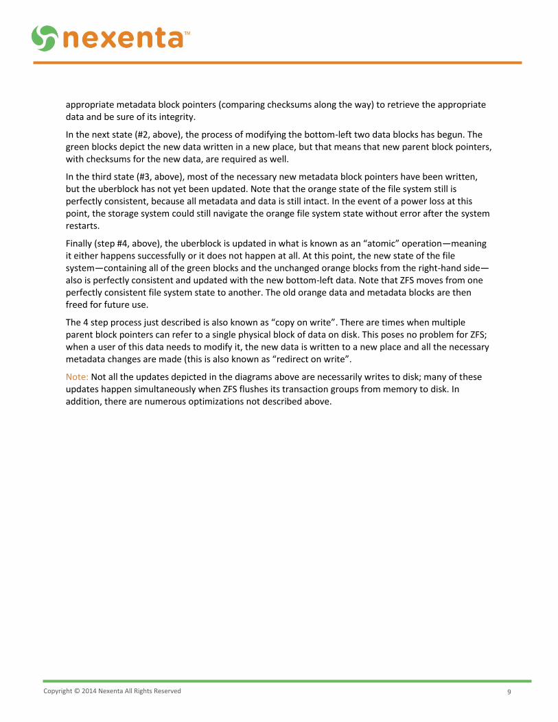
In the following diagram, if a snapshot of the all-orange state of the file system were desired, ZFS would just skip the freeing of all the old orange blocks and the orange uberblock step. (In concept, taking a snapshot actually is less work for ZFS, because it skips the of freeing old blocks step!) Finding data in the current file system is as easy as following the relevant pointers from the green uberblock, and finding data in the snapshot is simply following the relevant pointers from the orange uberblock. Thus, in ZFS there is no need for separate “snapshot space”, and snapshots only consume as much space as is changed in the file system since the snapshot was taken.
Figure 4: Updates are atomic – the file system state is always consistent
Observe how ZFS’s application of “copy on write” in regards to snapshots is different than many other storage industry snapshot technologies. Some other file systems will perform a snapshot by literally copying the original data into a special snapshot space before the new write is completed in the original location. For others, new writes after a snapshot are directed into the special snapshot space, and when the snapshot is deleted, those writes are merged back into the original locations.
Figure 5: ZFS snapshots simply keep some pointers that would have otherwise been discarded
Initial Block Tree COW Some Data
COW Metadata Update Uberblocks and Free
Current State SnapShot
Copyright © 2014 Nexenta All Rights Reserved
11
ZFS Replication
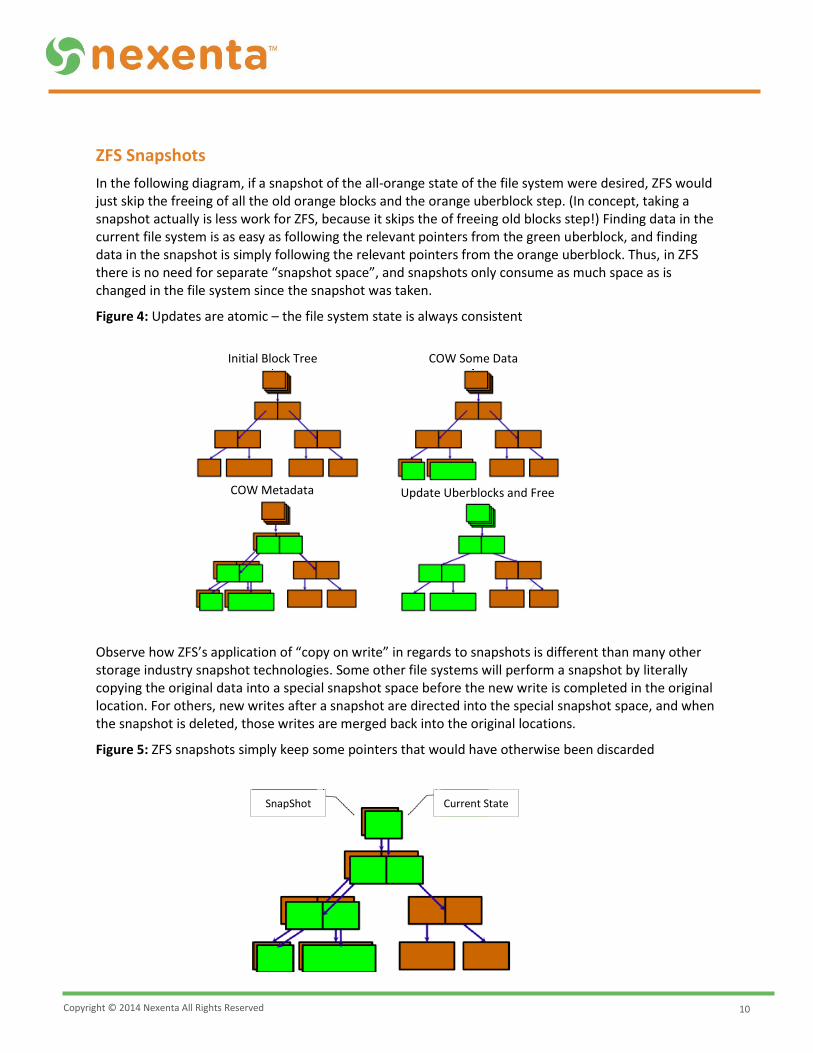
The simplicity of ZFS snapshots helps us understand ZFS’s built-in replication feature known as “ZFS send and receive”. Replication is based on a concept known as “birth times”. In addition to checksum and pointer information, each “parent” block contains the “birth times” of the children to which it points. The birth time is simply the transaction group number for the block that was written. With birth times, it becomes an easy task to identify any changes made between times 19 and 37. Refer to Figure 6 for an example.
Figure 6: Using birth times to determine any changes between two points in time
If ZFS replicates updates between snapshots taken at time 19 and time 37, the logical process would be as follows: Starting from the orange uberblock, the question asked is whether the child’s birth time (37) is greater than 19? Yes, the state of the file system has changed and all changes should be found and sent. Moving down and left first, the question asked is whether the child’s birth time (37 again) is greater than 19? Yes! Again moving down and left; is 37 greater than 19? Yes! So send that bottom-left orange data block, then back up one level and move right; is 25 greater than 19? Yes! So send that green data block, then back up one level and move right; is 19 greater than 19? No! This means that nothing on the right side of the above diagram has changed and there is no need to traverse any further into that part of the file system.
Note: that any parent block always is as “new” as its newest child. It is also worth noting that only the data in those data blocks are sent and not the various block pointers. Data changes are applied on the target file system but the block pointer tree may be different! This allows for differing compression levels on source and target, deduplication, or any other ZFS metadata-related configurable options!
This differs significantly from other replication technologies that require complete file system bitmaps and comparisons of the entire file system state in order to know what changes to send. Rsync, must examine the entire file structure on both source and target to determine if anything has changed. This can result in hours of metadata analysis even to send changes to one file!
Note: NexentaStor’s Auto-Sync replication feature uses ZFS’s built-in send and receive technology, as described in this paper. Auto-Tier uses rsync which, while less efficient, offers the ability to replicate between NexentaStor and non-ZFS storage.
Copyright © 2014 Nexenta All Rights Reserved
12
ZFS Resilvering
Much like replication, resilvering with ZFS technology is efficient due to its file system layout and use of birth times. More specifically, there are three traditions used by most file systems upon which ZFS improves significantly:
Creating a New RAID Set
In traditional file systems, when a new mirror (e.g., RAID-1 or RAID-10) or a new RAID stripe (e.g., RAID-5 or RAID-6) is created, the disks have to be initialized. Initialization means that disks are either written with all zeroes or by copying one disk to the other (or XOR-ing them together). The goal is to make all disks in the RAID set self-consistent but in reality the data on the drives is irrelevant! Instead of this wasted effort, as depicted in Figure 7; ZFS only copies “live” or relevant blocks of data when creating mirrors or RAID groups. This means that it takes nearly zero time to create and “initialize” new RAID sets! Compare that to the time required to initialize today’s highest capacity disks.
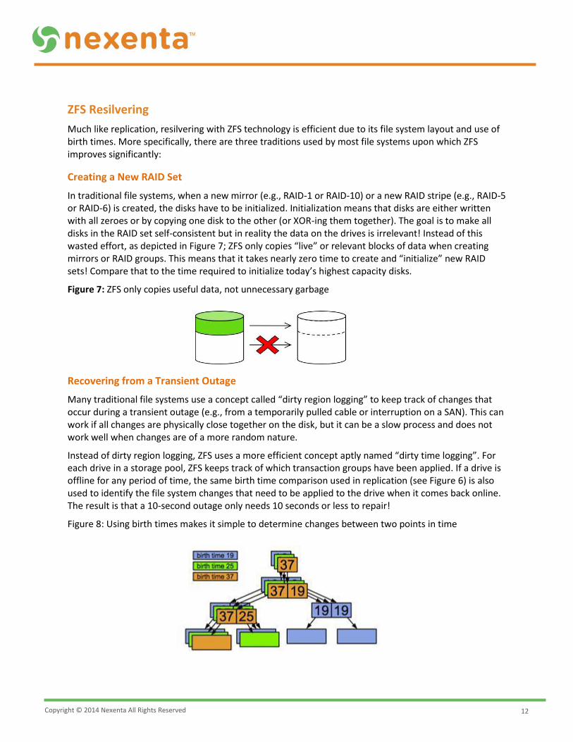
Figure 7: ZFS only copies useful data, not unnecessary garbage
Recovering from a Transient Outage
Many traditional file systems use a concept called “dirty region logging” to keep track of changes that occur during a transient outage (e.g., from a temporarily pulled cable or interruption on a SAN). This can work if all changes are physically close together on the disk, but it can be a slow process and does not work well when changes are of a more random nature.
Instead of dirty region logging, ZFS uses a more efficient concept aptly named “dirty time logging”. For each drive in a storage pool, ZFS keeps track of which transaction groups have been applied. If a drive is offline for any period of time, the same birth time comparison used in replication (see Figure 6) is also used to identify the file system changes that need to be applied to the drive when it comes back online. The result is that a 10-second outage only needs 10 seconds or less to repair!
Figure 8: Using birth times makes it simple to determine changes between two points in time
Copyright © 2014 Nexenta All Rights Reserved
13
Replacing a Failed Drive
Much like the creation of a new RAID set, when a drive is replaced in traditional file systems, the entire drive is reconstructed from the surviving members of the RAID set (either a RAID-5 mirrored disk or multiple disks) even if the failed disk had only a few bytes of relevant data. Imagine the time required and performance impact of reconstructing 4TB of data when only 50MB mattered! In addition, traditional file systems reconstruct drives from one end to the other without any thought to the importance of the data on the disk. Consider if the root directory inode was one of the last things to be reconstructed on a replacement drive, and a second disk failure occurred before the reconstruction completed.
Perhaps worse than the wasted effort and non-prioritized order, traditional file systems have no significant means to check the validity of the reconstructed data along the way. Remember the RAID-5 write hole discussion above, if a data update had completed without the associated parity update, the reconstruction process would use the incorrect parity to “correct,” i.e., corrupt, the data on the replacement drive.
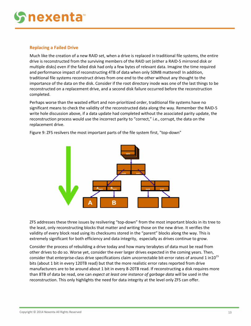
Figure 9: ZFS resilvers the most important parts of the file system first, "top-down"
ZFS addresses these three issues by resilvering “top-down” from the most important blocks in its tree to the least, only reconstructing blocks that matter and writing those on the new drive. It verifies the validity of every block read using its checksums stored in the “parent” blocks along the way. This is extremely significant for both efficiency and data integrity, especially as drives continue to grow.
Consider the process of rebuilding a drive today and how many terabytes of data must be read from other drives to do so. Worse yet, consider the ever larger drives expected in the coming years. Then, consider that enterprise-class drive specifications claim uncorrectable bit-error rates of around 1 in1015
bits (about 1 bit in every 120TB read) but that the more realistic error rates reported from drive manufacturers are to be around about 1 bit in every 8-20TB read. If reconstructing a disk requires more than 8TB of data be read, one can expect at least one instance of garbage data will be used in the reconstruction. This only highlights the need for data integrity at the level only ZFS can offer.