WHITE PAPER Balconies and thermal bridging -...
16
WHITE PAPER : Balconies and thermal bridging
Transcript of WHITE PAPER Balconies and thermal bridging -...
WHITE PAPER: Balconies and thermal bridging
Balconies and thermal bridging
2
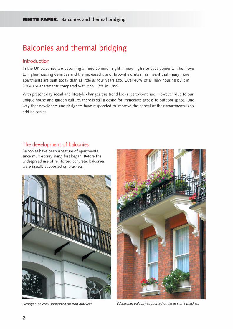
The development of balconiesBalconies have been a feature of apartments since multi-storey living first began. Before thewidespread use of reinforced concrete, balconieswere usually supported on brackets.
Georgian balcony supported on iron brackets Edwardian balcony supported on large stone brackets
WHITE PAPER: Balconies and thermal bridging
IntroductionIn the UK balconies are becoming a more common sight in new high rise developments. The move
to higher housing densities and the increased use of brownfield sites has meant that many more
apartments are built today than as little as four years ago. Over 40% of all new housing built in
2004 are apartments compared with only 17% in 1999.
With present day social and lifestyle changes this trend looks set to continue. However, due to our
unique house and garden culture, there is still a desire for immediate access to outdoor space. One
way that developers and designers have responded to improve the appeal of their apartments is to
add balconies.

WHITE PAPER: Balconies and thermal bridging
From the 1930s onwards, concrete was the materialof choice for balconies. The projecting balcony wasusually a direct extension of the floor slab.
3
Classic 1930s balcony design with projecting concrete slab and brick balustrade
Balconies at Highpointin Highgate, London,an icon of their day
4
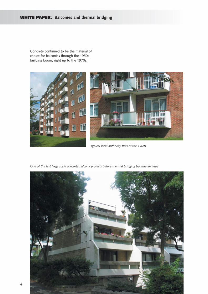
Concrete continued to be the material ofchoice for balconies through the 1950sbuilding boom, right up to the 1970s.
Typical local authority flats of the 1960s
One of the last large scale concrete balcony projects before thermal bridging became an issue
WHITE PAPER: Balconies and thermal bridging
WHITE PAPER: Balconies and thermal bridging
5
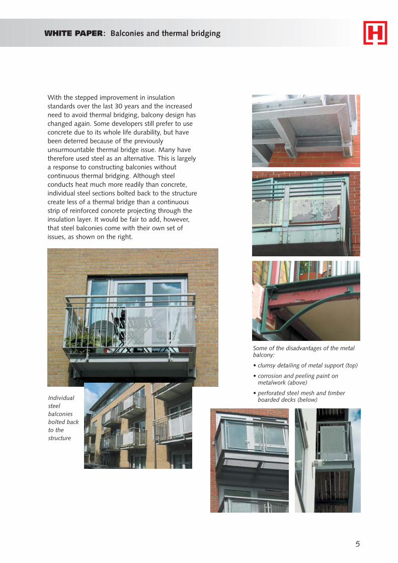
With the stepped improvement in insulationstandards over the last 30 years and the increasedneed to avoid thermal bridging, balcony design haschanged again. Some developers still prefer to useconcrete due to its whole life durability, but havebeen deterred because of the previouslyunsurmountable thermal bridge issue. Many havetherefore used steel as an alternative. This is largelya response to constructing balconies withoutcontinuous thermal bridging. Although steelconducts heat much more readily than concrete,individual steel sections bolted back to the structurecreate less of a thermal bridge than a continuousstrip of reinforced concrete projecting through theinsulation layer. It would be fair to add, however,that steel balconies come with their own set ofissues, as shown on the right.
Individualsteelbalconiesbolted backto thestructure
Some of the disadvantages of the metalbalcony:
• clumsy detailing of metal support (top)
• corrosion and peeling paint onmetalwork (above)
• perforated steel mesh and timberboarded decks (below)
6
WHITE PAPER: Balconies and thermal bridging
Building Regulations and thermalbridgingThe 2002 edition of Part L1 of the BuildingRegulations states in paragraph 1.30 that “Thebuilding fabric should be constructed so that thereare no significant thermal bridges or gaps in theinsulation layer(s) within the various elements ofthe fabric . .”
Unfortunately, the standard reference on detailingto avoid thermal bridging, ‘Limiting thermalbridging and air leakage: Robust constructiondetails for dwellings and similar buildings’ does not contain a balcony detail. However, the messagefrom the Building Regulations is clear, do not bridgethe insulation layer. As insulation standardscontinue to rise, the importance of eliminatingthermal bridging becomes even greater.
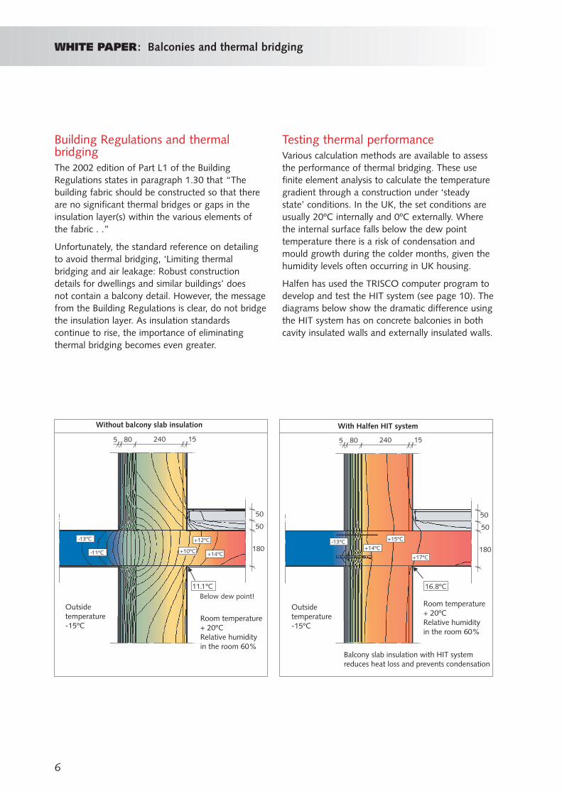
Testing thermal performanceVarious calculation methods are available to assessthe performance of thermal bridging. These usefinite element analysis to calculate the temperaturegradient through a construction under ‘steadystate’ conditions. In the UK, the set conditions areusually 20ºC internally and 0ºC externally. Wherethe internal surface falls below the dew pointtemperature there is a risk of condensation andmould growth during the colder months, given thehumidity levels often occurring in UK housing.
Halfen has used the TRISCO computer program todevelop and test the HIT system (see page 10). Thediagrams below show the dramatic difference usingthe HIT system has on concrete balconies in bothcavity insulated walls and externally insulated walls.
16.8ºC
+14ºC
+15ºC
+17ºC
80 152405
50
180
50
-13ºC-13ºC
-11ºC +10ºC
+12ºC
+14ºC
80 152405
50
180
50
11.1ºCBelow dew point!
Without balcony slab insulation With Halfen HIT system
Room temperature+ 20ºCRelative humidityin the room 60%
Room temperature+ 20ºCRelative humidityin the room 60%
Outsidetemperature-15ºC
Outsidetemperature-15ºC
Balcony slab insulation with HIT systemreduces heat loss and prevents condensation
WHITE PAPER: Balconies and thermal bridging
7
The condensation riskDesigners and builders have learnt throughexperience that if the insulation layer is bridged by a projecting concrete balcony, the likely result is condensation and mould on the underside of the concrete slab.
This is an extract from an article by charteredsurveyor Peter Fall in the Newcastle Journal:
“Our homeowner this week was suffering from a problem of constant dampness on the wall justbelow the ceiling above his “balcony” doors. Hethought that the water must be leaking throughthe doorway of the flat above and down into hisroom. The problem was a little more complex thanthat. Having checked the doorway above and theupper balcony, we soon found that no matter howmuch water was played onto the surface of thedoor upstairs, none of it came through to the flatbeneath.
The problem in this instance was the reinforcedconcrete cantilever balcony. This projected throughto the inside face where the warm moistatmosphere of the living room condensed on the plaster finish to the cold reinforced concrete.The reinforced concrete balcony in effect bridged across the thermal insulation to the wall. Hence the expression ‘cold bridging’.”
Other considerations
Drainage
Concrete balconies are normally finished with awaterproof membrane and water is usually thendirected to a drainage outlet. Alternatively, forsmaller balconies, rainwater is sometimes drainedaway by means of a small overflow pipe ordischarged over the front edge.
Steel and timber balconies often have a permeabledeck. The deck can be timber decking or steelmesh, which allows water to drip down onto thebalconies directly below. This type of ‘open’ deck is unsatisfactory for balconies on lower floors. Not
only is the balcony less useable because of drippingrainwater from upper balconies, but there is alsothe chance of spillages from upper balconies, apotential health and safety hazard.
For the proper enjoyment of lower balconies, thebalcony deck should be impermeable and surfacewater should be drained away.
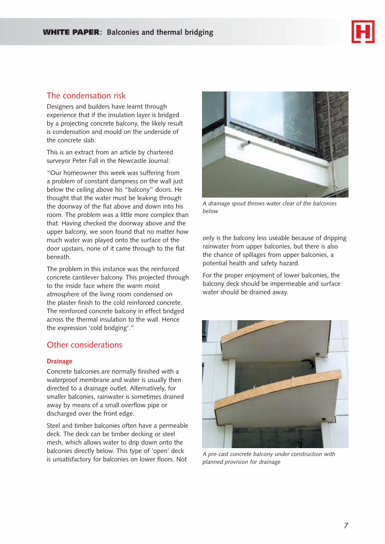
A pre-cast concrete balcony under construction withplanned provision for drainage
A drainage spout throws water clear of the balconiesbelow
8
WHITE PAPER: Balconies and thermal bridging
Marine environments
It is no surprise that many coastal developmentsinclude balconies to make the most of the views. However, the salt spray in marine environments canbe corrosive particularly to steel and, to a lesserextent, concrete.
Certain grades of stainless steel are specified fortheir corrosion resistance. These are mainly used for balustrading and fixings, but the high costnormally prohibits their use for the structuralcomponents of a balcony. Galvanising and otherprotective coatings are available for structural steel,but most require regular maintenance in order toretain their original appearance.
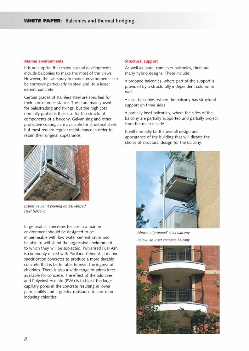
Above: a ‘propped’ steel balcony
Below: an inset concrete balcony
Extensive paint peeling on galvanisedsteel balcony
In general all concretes for use in a marineenvironment should be designed to beimpermeable with low water cement ratios and be able to withstand the aggressive environment to which they will be subjected. Pulverised Fuel Ashis commonly mixed with Portland Cement in marinespecification concretes to produce a more durableconcrete that is better able to resist the ingress ofchlorides. There is also a wide range of admixturesavailable for concrete. The effect of the additivesand Polyvinyl Acetate (PVA) is to block the largecapillary pores in the concrete resulting in lowerpermeability and a greater resistance to corrosion-inducing chlorides.
Structural support
As well as ‘pure’ cantilever balconies, there aremany hybrid designs. These include:
• propped balconies, where part of the support isprovided by a structurally independent column orwall
• inset balconies, where the balcony has structuralsupport on three sides
• partially inset balconies, where the sides of thebalcony are partially supported and partially projectfrom the main facade
It will normally be the overall design andappearance of the building that will dictate thechoice of structural design for the balcony.

9
Preservation of view
One of the main purposes of a balcony is to takeadvantage of the view. In order to preserve ‘theview’ from inside the dwelling, the balustradingshould offer the minimum of obstruction. Clearglass is an obvious choice where enjoyment of theview is important. Vertical metal balustrading is alsocommonly used. Horizontal metal framing shouldnot be used because it is too easy to climb.
In all cases the balustrading must comply with therequirements of Building Regulation ApprovedDocument K2: Protection from falling. This sets aminimum height of 1100mm for all ‘guarding’. The guarding must be able to resist a minimumforce of 0.74 kN/m at the top edge.
In addition the balustrading must be able to resist a point load equivalent to 50 kgs applied through a 25mm square indent, when applied to the mostvulnerable point.
Clear glass balconies allow uninterrupted views frominside the apartment - etched horizontal lines are used asa safety feature
0.74 kN/m
MinimumHeight
1100mm
Balcony
Building Regulation requirements for the guardingof external balconies in single family dwellings
Horizontal rails should be avoided -a fine mesh is used here to preventclimbing the rails
Perforated metal panels are used toprovide a good level of privacy
Narrow, closely spaced verticalmetal bars allow a virtuallyuninterrupted view
WHITE PAPER: Balconies and thermal bridging
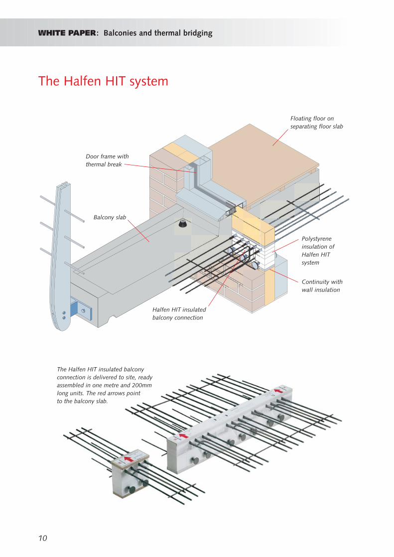
The Halfen HIT system
10
WHITE PAPER: Balconies and thermal bridging
Balcony slab
Halfen HIT insulatedbalcony connection
Floating floor onseparating floor slab
Continuity withwall insulation
Polystyreneinsulation ofHalfen HITsystem
Door frame withthermal break
The Halfen HIT insulated balconyconnection is delivered to site, readyassembled in one metre and 200mmlong units. The red arrows point to the balcony slab.
WHITE PAPER: Balconies and thermal bridging
11
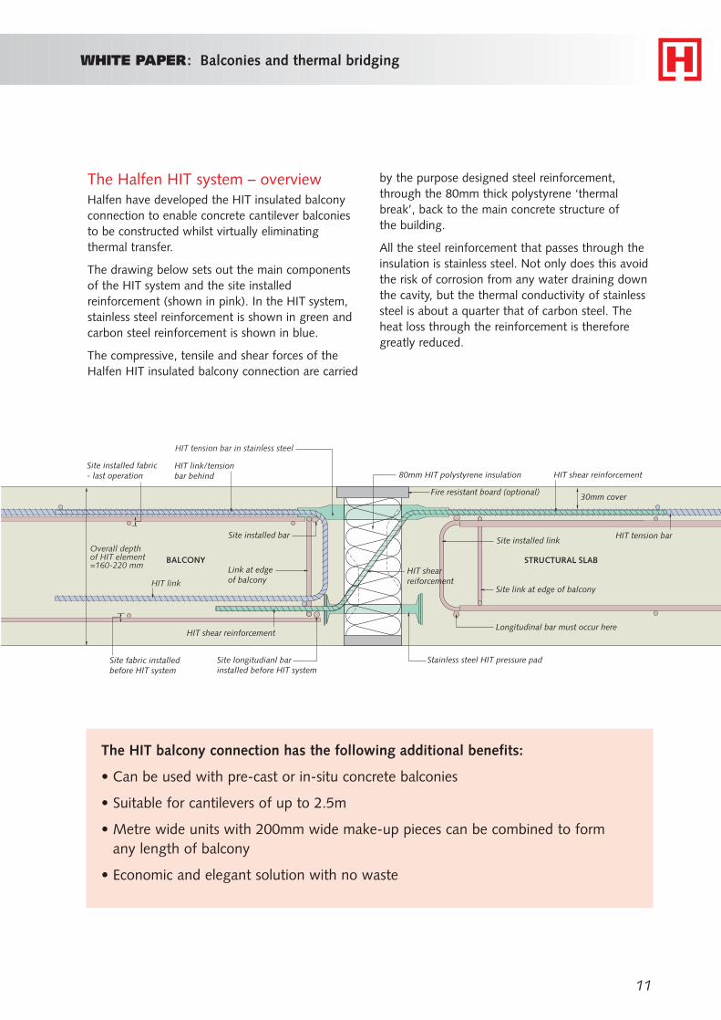
The Halfen HIT system – overviewHalfen have developed the HIT insulated balconyconnection to enable concrete cantilever balconiesto be constructed whilst virtually eliminatingthermal transfer.
The drawing below sets out the main componentsof the HIT system and the site installedreinforcement (shown in pink). In the HIT system,stainless steel reinforcement is shown in green andcarbon steel reinforcement is shown in blue.
The compressive, tensile and shear forces of theHalfen HIT insulated balcony connection are carried
The HIT balcony connection has the following additional benefits:
• Can be used with pre-cast or in-situ concrete balconies
• Suitable for cantilevers of up to 2.5m
• Metre wide units with 200mm wide make-up pieces can be combined to formany length of balcony
• Economic and elegant solution with no waste
by the purpose designed steel reinforcement,through the 80mm thick polystyrene ‘thermalbreak’, back to the main concrete structure of the building.
All the steel reinforcement that passes through theinsulation is stainless steel. Not only does this avoidthe risk of corrosion from any water draining downthe cavity, but the thermal conductivity of stainlesssteel is about a quarter that of carbon steel. Theheat loss through the reinforcement is thereforegreatly reduced.
HIT link
Overall depthof HIT element=160-220 mm
HIT tension bar in stainless steel
BALCONY
Site installed fabric- last operation
Site fabric installedbefore HIT system
Site longitudianl barinstalled before HIT system
HIT shear reinforcement
Link at edge of balcony
HIT link/tensionbar behind
Site installed bar
Fire resistant board (optional) 30mm cover
HIT shear reinforcement
HIT tension bar
STRUCTURAL SLAB
Longitudinal bar must occur here
Stainless steel HIT pressure pad
80mm HIT polystyrene insulation
HIT shearreiforcement
Site installed link
Site link at edge of balcony
12
WHITE PAPER: Balconies and thermal bridging
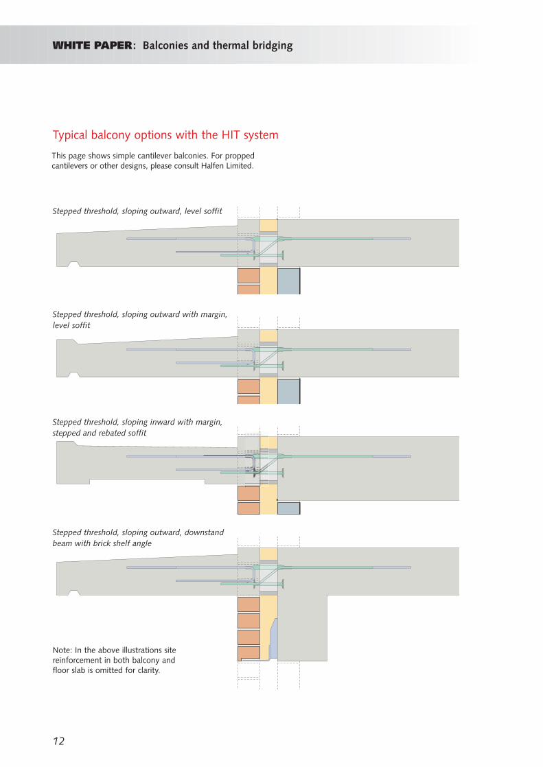
Note: In the above illustrations sitereinforcement in both balcony andfloor slab is omitted for clarity.
Typical balcony options with the HIT system
Stepped threshold, sloping outward, level soffit
Stepped threshold, sloping outward with margin,level soffit
Stepped threshold, sloping inward with margin,stepped and rebated soffit
Stepped threshold, sloping outward, downstandbeam with brick shelf angle
This page shows simple cantilever balconies. For proppedcantilevers or other designs, please consult Halfen Limited.

WHITE PAPER: Balconies and thermal bridging
13
Typical balcony detail
Halfen HIT system
Suspended ceiling to complywith Approved Document E
‘Soft’ joints
Floating floor to complywith Approved Document E
Double glazed doorgives access to balcony
Halfen cast-inchannels providefixings forbalustrading
Cross section through balcony doors
Isometric of balcony
Floor slab
Balcony slab
Isometric of metre long HIT unit
Polystyreneinsulation
Tension bars
Pressure pads
Shear reinforcement
Continuity of wall insulation
14
WHITE PAPER: Balconies and thermal bridging
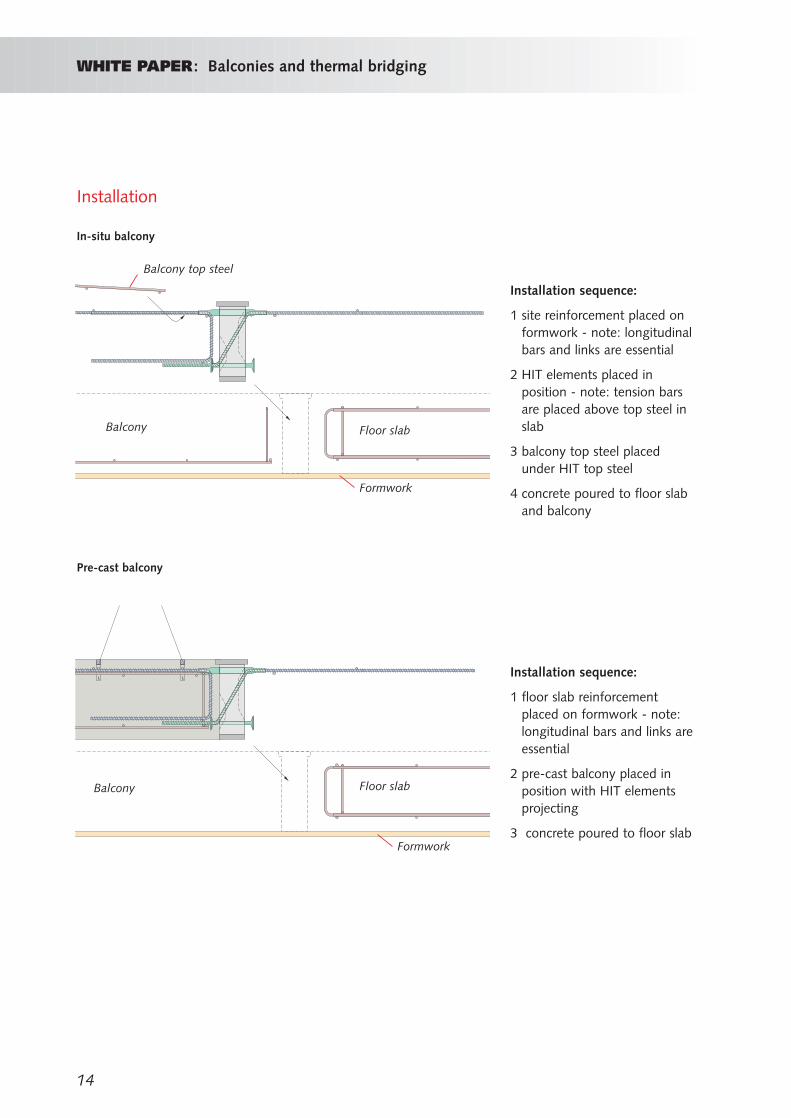
Installation
In-situ balcony
Pre-cast balcony
Installation sequence:
1 site reinforcement placed onformwork - note: longitudinalbars and links are essential
2 HIT elements placed inposition - note: tension barsare placed above top steel inslab
3 balcony top steel placedunder HIT top steel
4 concrete poured to floor slaband balcony
Installation sequence:
1 floor slab reinforcementplaced on formwork - note:longitudinal bars and links areessential
2 pre-cast balcony placed inposition with HIT elementsprojecting
3 concrete poured to floor slab
Balcony top steel
Balcony
Balcony Floor slab
Floor slab
Formwork
Formwork
15
WHITE PAPER: Balconies and thermal bridging
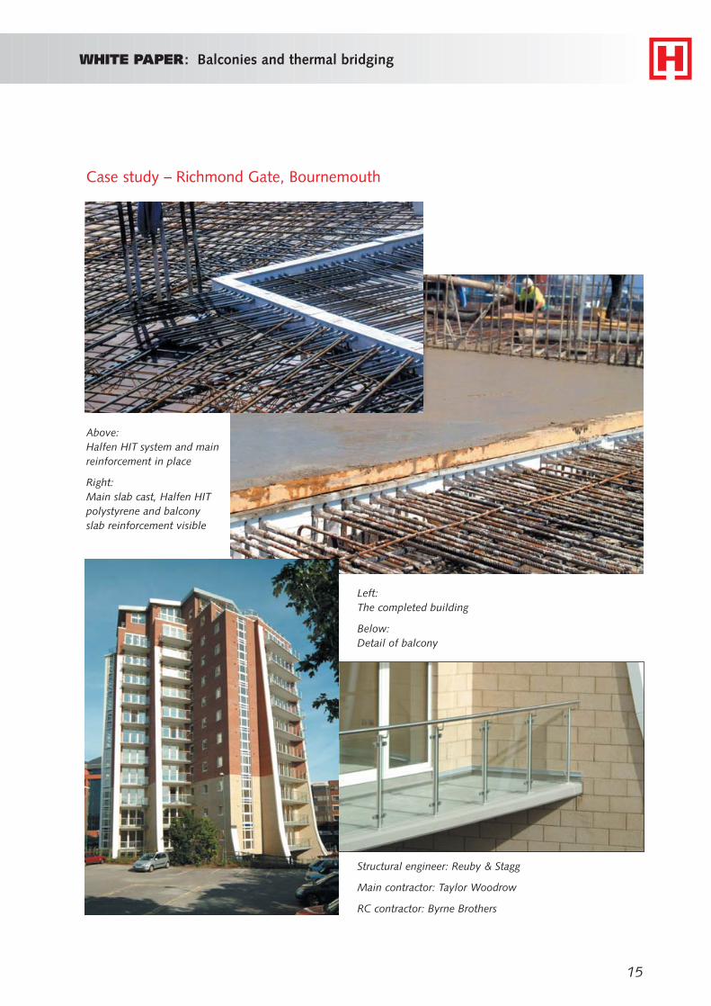
Case study – Richmond Gate, Bournemouth
Above: Halfen HIT system and mainreinforcement in place
Right:Main slab cast, Halfen HITpolystyrene and balconyslab reinforcement visible
Structural engineer: Reuby & Stagg
Main contractor: Taylor Woodrow
RC contractor: Byrne Brothers
Left: The completed building
Below:Detail of balcony
HALFEN.DEHAY O U R B E S T C O N N E C T I O N S
For further information about the Halfen HIT system, please contact:HALFEN Ltd, Humphrys Road, Woodside Estate, Dunstable LU5 4TP
Tel: +44 (0)8705 316300 - Fax: +44 (0)8705 316304www.halfen.co.uk
ReferencesBuilding Regulations
Approved Document K, Protection from falling, collision and impact
Approved Document L, Conservation of fuel and power
British Standards
BS 6180: 1995 Code of practice for protective barriers in and aboutbuildings
October 2004