White Paper… - Autotech Controls · Unit (CPU) according to the ladder program and the ... i.e.,...
2
White Paper… Interfacing Absolute Position Decoders . . . Microcomputers and PLCs are sequential logic devices. In contrast to a real-time hardware logic, which can perform many operations at the same time, a PLC can perform only a single operation before proceeding to the next logical step. The figure describes the logical operation of a PLC, which is cyclical in nature. During the I/O scan, the PLC looks at the input terminals and activates the outputs based on the ladder logic. During the processor scan, the new input data is processed by the Central Processing Unit (CPU) according to the ladder program and the outputs are updated during the next I/O scan. This cycle repeats again and again. The expression “garbage in, garbage out” fits very well with the PLC. If the input data is invalid or incorrect, the corresponding machine operation will also be incorrect. Therefore, it is very important that when the PLC reads the decoder input during the I/O scan, the decoder data is valid and free of any ambiguities. There are two main inherent characteristics of electronic devices that could cause wrong decoder data into the PLC: a) PLC Reading the Changing Bit Pattern: As we all know, a BCD, binary, or gray code number is composed of various bits that change state when decoder position passes from one number to the next. Inherently, in Gray Code only 1 bit changes state when changing from one number to the next, while in BCD or Binary data more than one bits may change for each number change. Let us consider the example of changing decoder position from 199° to 200°. In a BCD code, for this 1° change of position, 6 bits will change state, i.e., 100, 80, 10, 8, and 1 bits go LOW and 200 bit will go HIGH. And, due to the reaction time of electronic components, all these bits do not change state at the same time. At a given time when PLC reads the data, some bits might have gone LOW while others may still be HIGH. Therefore, while reading the above changing bit pattern the PLC is liable to read a wrong number. b) Reaction Time of Input Modules: PLC I/O modules, even the TTL compatible ones, have lengthy and inconsistent time delays when they change their logic state. This inconsistency gets further compounded by long wiring runs between the decoder and the PLC, and also the limited current drive capab- ility of the decoder outputs. In the above example, when the input to the I/O modules goes from 199° to 200°, the output may stay at 000 for a time, depend- ing on the I/O module reaction time. An I/O scan during this time (2 to 10 ms in typical installations) will read false data to the PLC. The solid line is the field side of the I/O module and the dashed line is the PLC side. During the switching time (TS), the decoder information as seen on the PLC side is 0, which is invalid. Even dedicated microprocessor controls with faster scan times are faced with the above two problems, though to a lesser degree. In microprocessors the TS is in microseconds (μs) and software can be designed to ignore inconsistent data. If your micro- processor does not have this software provision or if you are using a PLC, the hardware synchronisation described below must be used to assure the integrity of the incoming decoder data. 1/O Scan PROCESSOR SCAN 199 200 Bit 100, 80, 10, 8, 1 Bit 200 t ”On” ts = t ”on” - t “off” t “Off” : I/O turning off delay t “On” : I/O turning on delay ts : Switching interval t “off” Field side of I/O PLC side of I/O 199 200 Bit 100, 80, 10, 8, 1 Bit 200 Autotech offers one of the broadest lines of Encoders in the industry.
Transcript of White Paper… - Autotech Controls · Unit (CPU) according to the ladder program and the ... i.e.,...
White Paper…
Interfacing Absolute Position Decoders . . .Microcomputers and PLCs are sequential logicdevices. In contrast to a real-time hardware logic,which can perform many operations at the same time,a PLC can perform only a single operation beforeproceeding to the next logical step. The figure describes the logical operation of a PLC, which is cyclical in nature. During the I/O scan, the PLC looks at the input terminals and activates the outputsbased on the ladderlogic. During theprocessor scan, the new input data is processed by the Central Processing Unit (CPU) according to the ladder program and the outputs are updated during the next I/O scan. This cycle repeats again and again.
The expression “garbage in, garbage out” fits verywell with the PLC. If the input data is invalid orincorrect, the corresponding machine operation willalso be incorrect. Therefore, it is very important thatwhen the PLC reads the decoder input during theI/O scan, the decoder data is valid and free of anyambiguities.
There are two main inherent characteristics ofelectronic devices that could cause wrong decoderdata into the PLC:
a) PLC Reading the Changing Bit Pattern:As we all know, a BCD, binary, or gray code numberis composed of various bits that change state whendecoder position passes from one number to thenext. Inherently, in Gray Code only 1 bit changesstate when changing from one number to the next,while in BCD or Binary data more than one bits maychange for each number change. Let us considerthe example of changing decoder position from 199°
to 200°. In a BCD code, for this 1° change of position,6 bits will change state, i.e., 100, 80, 10, 8, and 1 bitsgo LOW and 200 bit will go HIGH. And, due to thereaction time of electronic components, all these bitsdo not change state at the same time. At a given timewhen PLC reads the data, some bits might have goneLOW while others may still be HIGH. Therefore, whilereading the above changing bit pattern the PLC is liableto read a wrong number.
b) Reaction Time of Input Modules:PLC I/O modules, even the TTL compatible ones,have lengthy and inconsistent time delays when theychange their logic state. This inconsistency gets furthercompounded by long wiring runs between the decoderand the PLC, and also the limited current drive capab-ility of the decoder outputs. In the above example,when the input to the I/O modules goes from 199° to200°, the output may stay at 000 for a time, depend-ing on the I/O module reaction time.
An I/O scan during this time (2 to 10 ms in typicalinstallations) will read false data to the PLC. The solidline is the field side of the I/O module and the dashedline is the PLC side. During the switching time (TS), the decoder information as seen on the PLC side is 0, which is invalid.
Even dedicated microprocessor controls with faster scan times are faced with the above two problems, though to a lesser degree. In microprocessors the TS is in microseconds (µs) and software can be designed to ignore inconsistent data. If your micro-processor does not have this software provision or if you are using a PLC, the hardware synchronisationdescribed below must be used to assure the integrity of the incoming decoder data.
1/O Scan
PROCESSOR SCAN
199
200 Bit
100, 80, 10, 8, 1 Bit
200
t ”On”
ts = t ”on” - t “off”t “Off” : I/O turning off delayt “On” : I/O turning on delayts : Switching interval
t “off”
Field side of I/OPLC side of I/O
199
200 Bit
100, 80, 10, 8, 1 Bit
200
Autotech offers one of the broadest lines of Encoders in the industry.
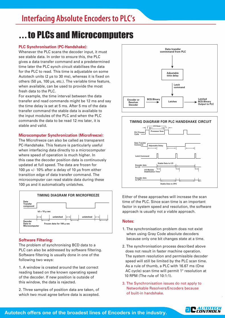
. . . to PLCs and MicrocomputersPLC Synchronisation (PC-Handshake):Whenever the PLC scans the decoder input, it must see stable data. In order to ensure this, the PLCgives a data transfer command and a predeterminedtime later the PLC synch circuit stabilises the data for the PLC to read. This time is adjustable on some Autotech units (2 µs to 30 ms), whereas it is fixed on others (50 µs, 100 µs, etc.). The variable time feature, when available, can be used to provide the most fresh data to the PLC.For example, the time interval between the datatransfer and read commands might be 12 ms and saythe time delay is set at 5 ms. After 5 ms of the datatransfer command the stable data is available to the input modules of the PLC and when the PLC commands the data to be read 12 ms later, it is stable and valid.
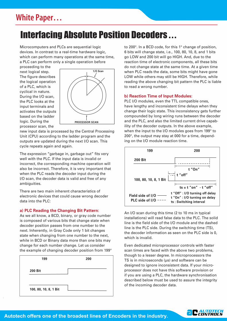
Microcomputer Synchronization (Microfreeze):The Microfreeze can also be called as transparentPC-Handshake. This feature is particularly usefulwhen interfacing data directly to a microcomputerwhere speed of operation is much higher. Inthis case the decoder position data is continuouslyupdated at full speed. The data are frozen for100 µs +/- 10% after a delay of 10 µs from eithertransition edge of data transfer command. Themicrocomputer can read stable data during these100 µs and it automatically unlatches.
Either of these approaches will increase the scantime of the PLC. Since scan time is an importantfactor in system speed and resolution, the software approach is usually not a viable approach.
Notes:
1. The synchronisation problem does not existwhen using Gray Code absolute decodersbecause only one bit changes state at a time.
2. The synchronisation process described abovedoes not result in faster machine operation.The system resolution and permissible decoderspeed will still be limited by the PLC scan time.As a rule of thumb, a PLC with 16.67 ms (OneAC cycle) scan time will permit 1° resolution at
10 RPM (The rule of 10:1:1).
3. The Synchronisation issues do not apply toNetworkable Resolvers/Encoders becauseof built-in handshake.
Software Filtering:The problem of synchronising BCD data to aPLC can also be addressed by software filtering.Software filtering is usually done in one of thefollowing two ways:
1. A window is created around the last correctreading based on the known operating speedof the decoder. If new position is outside ofthis window, the data is rejected.
2. Three samples of position data are taken, ofwhich two must agree before data is accepted.
TIMING DIAGRAM FOR MICROFREEZE
DataTransfercompound
DecoderData toMicrocomputer
Frozen data for 100 µ sec
td = 10 µ sec
unlatched unlatched
Data transfercommmand from PLC
Adjustabletime delay
LatchesLatched BCD/BinaryOutput to PLC
Latchcommand
BCD/Binary
PLC ProcessCycle
Adjustable Delay
Stable Data to I/O
Stable Data to CPU
Latch Command
Encoder datato I/O
Encoder datato CPU
I/O ModuleStabilisation Time
Data TransferCommand
Processor Scan
I/O Scan
Encoder orResolverDecoder
TIMING DIAGRAM FOR PLC HANDSHAKE CIRCUIT
Interfacing Absolute Encoders to PLC’s
Autotech offers one of the broadest lines of Encoders in the industry.