Whirlpool Wed7500vw Use And Care Manual · PDF fileIf you have a Whirlpool washer model...
20
240-VOLT ELECTRIC DRYER Use & Care Guide For questions about features, operation/performance, parts, accessories or service, call: 1-800-253-1301. or visit our website at...www.whirlpool.com Table of Contents ................................................. 2 W10189310B ®
-
Upload
truongcong -
Category
Documents
-
view
227 -
download
4
Transcript of Whirlpool Wed7500vw Use And Care Manual · PDF fileIf you have a Whirlpool washer model...
240-VOLTELECTRIC DRYER
Use & Care GuideFor questions about features, operation/performance,parts, accessories or service, call: 1-800-253-1301.
or visit our website at...www.whirlpool.com
Table of Contents ................................................. 2
W10189310B
®
2
TABLE OF CONTENTSDRYER SAFETY..............................................................................3INSTALLATION REQUIREMENTS................................................4
Tools and Parts ............................................................................4Options.........................................................................................4Location Requirements................................................................4Electrical Requirements ...............................................................6Venting Requirements..................................................................7
INSTALLATION INSTRUCTIONS..................................................8Electrical Connection ...................................................................8Plan Vent System.......................................................................11Install Vent System.....................................................................12Connect Vent..............................................................................12Level Dryer .................................................................................13Complete Installation .................................................................13
DRYER USE ..................................................................................14Starting Your Dryer.....................................................................14Stopping and Restarting ............................................................14Changing Cycles and Temperatures .........................................14Controls ......................................................................................15Drying, Cycle and Temperature Tips .........................................15Cycles.........................................................................................15
DRYER CARE...............................................................................16Cleaning the Dryer Location.......................................................16Cleaning the Lint Screen ............................................................16Cleaning the Dryer Interior .........................................................17Cleaning the Control Panel ........................................................17Removing Accumulated Lint......................................................17Vacation and Moving Care.........................................................17
TROUBLESHOOTING ..................................................................18ASSISTANCE OR SERVICE.........................................................19WARRANTY ..................................................................................20
®
3
DRYER SAFETY
You can be killed or seriously injured if you don't immediately
You can be killed or seriously injured if you don't follow
All safety messages will tell you what the potential hazard is, tell you how to reduce the chance of injury, and tell you what canhappen if the instructions are not followed.
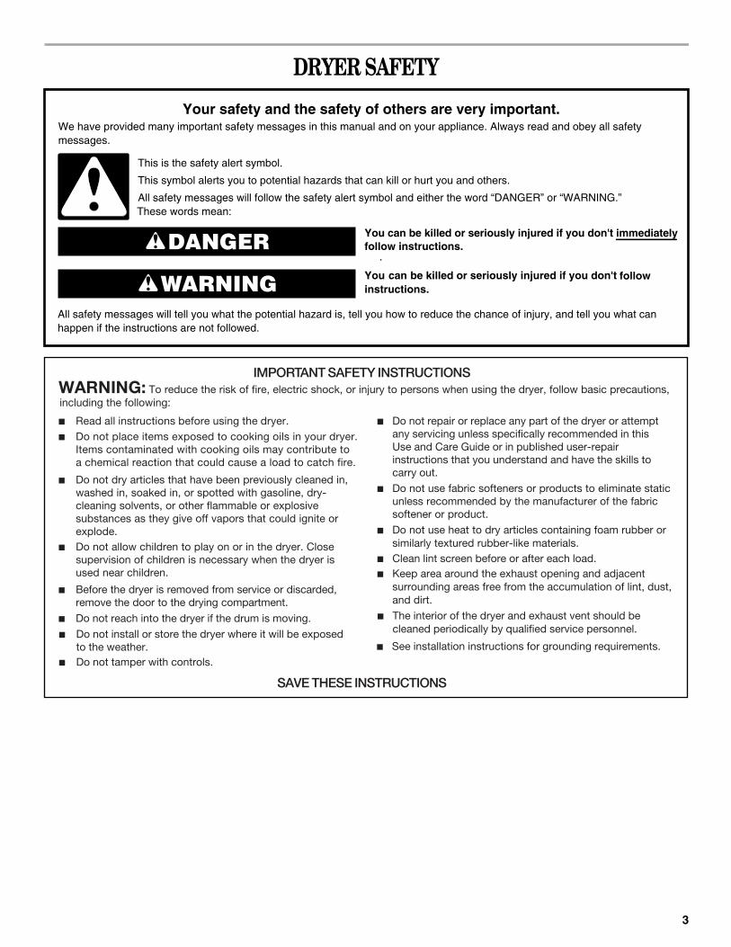
Your safety and the safety of others are very important.We have provided many important safety messages in this manual and on your appliance. Always read and obey all safety messages.
This is the safety alert symbol.
This symbol alerts you to potential hazards that can kill or hurt you and others.
All safety messages will follow the safety alert symbol and either the word “DANGER” or “WARNING.”These words mean:
follow instructions.
instructions.
DANGER
WARNING
IMPORTANT SAFETY INSTRUCTIONS To reduce the risk of fire, electric shock, or injury to persons when using the dryer, follow basic precautions, including the following:WARNING:
■ Read all instructions before using the dryer.■ Do not place items exposed to cooking oils in your dryer.
Items contaminated with cooking oils may contribute to a chemical reaction that could cause a load to catch fire.
■ Do not dry articles that have been previously cleaned in, washed in, soaked in, or spotted with gasoline, dry-cleaning solvents, or other flammable or explosive substances as they give off vapors that could ignite or explode.
■ Do not allow children to play on or in the dryer. Close supervision of children is necessary when the dryer is used near children.
■ Before the dryer is removed from service or discarded, remove the door to the drying compartment.
■ Do not reach into the dryer if the drum is moving.
■ Do not repair or replace any part of the dryer or attempt any servicing unless specifically recommended in this Use and Care Guide or in published user-repair instructions that you understand and have the skills to carry out.
■ Do not use fabric softeners or products to eliminate static unless recommended by the manufacturer of the fabric softener or product.
■ Do not use heat to dry articles containing foam rubber or similarly textured rubber-like materials.
■ Clean lint screen before or after each load.■ Keep area around the exhaust opening and adjacent
surrounding areas free from the accumulation of lint, dust, and dirt.
SAVE THESE INSTRUCTIONS
■ The interior of the dryer and exhaust vent should be cleaned periodically by qualified service personnel.
■ Do not install or store the dryer where it will be exposed to the weather.
■ Do not tamper with controls.
■ See installation instructions for grounding requirements.
4
INSTALLATION REQUIREMENTS
Tools and PartsTools neededGather the required tools and parts before starting installation. Read and follow the instructions provided with any tools listed here.
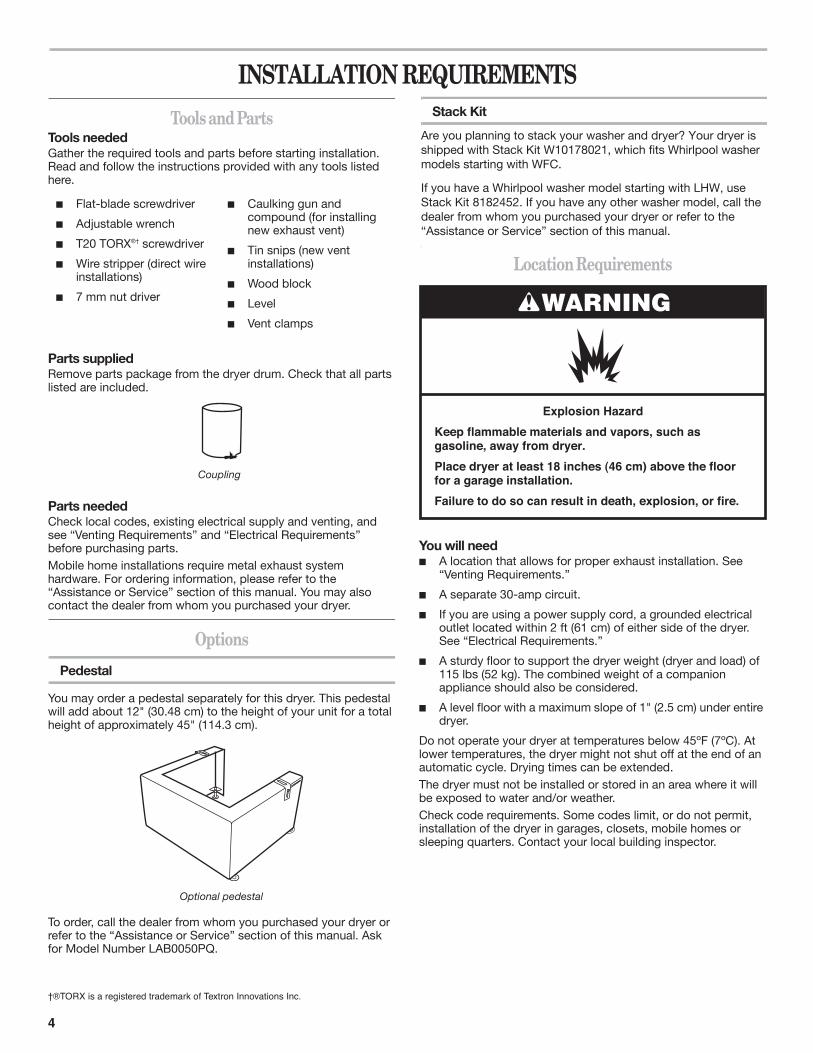
Parts supplied Remove parts package from the dryer drum. Check that all parts listed are included.
Parts neededCheck local codes, existing electrical supply and venting, and see “Venting Requirements” and “Electrical Requirements” before purchasing parts.Mobile home installations require metal exhaust system hardware. For ordering information, please refer to the “Assistance or Service” section of this manual. You may also contact the dealer from whom you purchased your dryer.
Options
Pedestal
You may order a pedestal separately for this dryer. This pedestal will add about 12" (30.48 cm) to the height of your unit for a total height of approximately 45" (114.3 cm).
To order, call the dealer from whom you purchased your dryer or refer to the “Assistance or Service” section of this manual. Ask for Model Number LAB0050PQ.
Location Requirements
You will needA location that allows for proper exhaust installation. See “Venting Requirements.”
A separate 30-amp circuit.
If you are using a power supply cord, a grounded electrical outlet located within 2 ft (61 cm) of either side of the dryer. See “Electrical Requirements.”
A sturdy floor to support the dryer weight (dryer and load) of 115 lbs (52 kg). The combined weight of a companion appliance should also be considered.
A level floor with a maximum slope of 1" (2.5 cm) under entire dryer.
Do not operate your dryer at temperatures below 45ºF (7ºC). At lower temperatures, the dryer might not shut off at the end of an automatic cycle. Drying times can be extended.The dryer must not be installed or stored in an area where it will be exposed to water and/or weather.Check code requirements. Some codes limit, or do not permit, installation of the dryer in garages, closets, mobile homes or sleeping quarters. Contact your local building inspector.
Flat-blade screwdriver
Adjustable wrench
T20 TORX®† screwdriver
Wire stripper (direct wire installations)
7 mm nut driver
Caulking gun and compound (for installing new exhaust vent)
Tin snips (new vent installations)
Wood block
Level
Vent clamps
Coupling
Optional pedestal
†®TORX is a registered trademark of Textron Innovations Inc.
WARNING
Explosion HazardKeep flammable materials and vapors, such asgasoline, away from dryer.Place dryer at least 18 inches (46 cm) above the floorfor a garage installation.Failure to do so can result in death, explosion, or fire.
Stack Kit
Are you planning to stack your washer and dryer? Your dryer isshipped with Stack Kit W10178021, which fits Whirlpool washermodels starting with WFC.
If you have a Whirlpool washer model starting with LHW, use Stack Kit 8182452. If you have any other washer model, call the dealer from whom you purchased your dryer or refer to the “Assistance or Service” section of this manual.
5
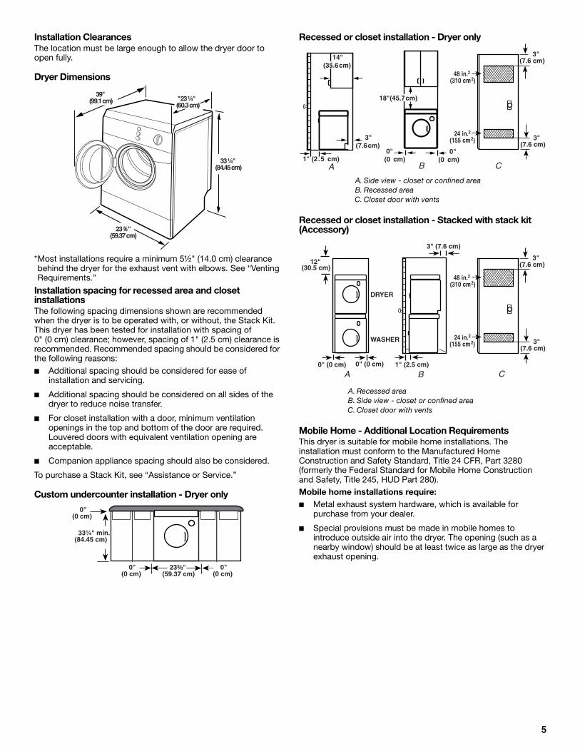
Installation ClearancesThe location must be large enough to allow the dryer door to open fully.
Dryer Dimensions
*Most installations require a minimum 5½" (14.0 cm) clearance behind the dryer for the exhaust vent with elbows. See “Venting Requirements.”
Installation spacing for recessed area and closet installationsThe following spacing dimensions shown are recommended when the dryer is to be operated with, or without, the Stack Kit. This dryer has been tested for installation with spacing of 0" (0 cm) clearance; however, spacing of 1" (2.5 cm) clearance is recommended. Recommended spacing should be considered for the following reasons: ■ Additional spacing should be considered for ease of
installation and servicing.
■ Additional spacing should be considered on all sides of the dryer to reduce noise transfer.
■ For closet installation with a door, minimum ventilation openings in the top and bottom of the door are required. Louvered doors with equivalent ventilation opening are acceptable.
■ Companion appliance spacing should also be considered.
To purchase a Stack Kit, see “Assistance or Service.”
Custom undercounter installation - Dryer only
Recessed or closet installation - Dryer only
Recessed or closet installation - Stacked with stack kit (Accessory)
Mobile Home - Additional Location RequirementsThis dryer is suitable for mobile home installations. The installation must conform to the Manufactured Home Construction and Safety Standard, Title 24 CFR, Part 3280 (formerly the Federal Standard for Mobile Home Construction and Safety, Title 245, HUD Part 280).Mobile home installations require:■ Metal exhaust system hardware, which is available for
purchase from your dealer.
■ Special provisions must be made in mobile homes to introduce outside air into the dryer. The opening (such as a nearby window) should be at least twice as large as the dryer exhaust opening.
33 ¼" (84.45 cm)
23 ³⁄₈"(59.37 cm)
39" (99.1 cm) 23 ¼"
(60.3 cm)*
0"(0 cm)
0"(0 cm)
0"(0 cm)
33¹⁄₄" min.(84.45 cm)
23³⁄₈"(59.37 cm)
A. Side view - closet or confined areaB. Recessed areaC. Closet door with vents
A. Recessed areaB. Side view - closet or confined areaC. Closet door with vents
BA
3"(7.6cm)
14"(35.6cm)
18"(45.7cm)
0"(0 cm)
0"(0 cm)
48 in.2 (310 cm2)
24 in.2(155 cm2)
3"(7.6 cm)
3"(7.6 cm)
C1" (2.5 cm)
DRYER
WASHER
(30.5 cm) 12"
0" (0 cm)
0" (0 cm)
A B C1" (2.5 cm)
48 in.2 (310 cm2)
24 in.2(155 cm2)
3"(7.6 cm)
3"(7.6 cm)
3" (7.6 cm)
6
Electrical RequirementsIt is your responsibility■ To contact a qualified electrical installer.
■ To be sure that the electrical connection is adequate and in conformance with the National Electrical Code, ANSI/NFPA 70-latest edition and all local codes and ordinances.
The National Electric Code requires a 4-wire supply connection for homes built after 1996, dryer circuits involved in remodeling after 1996 and all mobile home installations.
A copy of the above code standards can be obtained from: National Fire Protection Association, One Batterymarch Park, Quincy, MA 02269.
■ To supply the required 3 or 4 wire, single phase, 120/240 volt, 60 Hz., AC only electrical supply (or 3 or 4 wire, 120/208 volt electrical supply, if specified on the serial/rating plate) on a separate 30-amp circuit, fused on both sides of the line. A time-delay fuse or circuit breaker is recommended. Connect to an individual branch circuit. Do not have a fuse in the neutral or grounding circuit.
■ Do not use an extension cord.
■ If codes permit and a separate ground wire is used, it is recommended that a qualified electrician determine that the ground path is adequate.
Electrical ConnectionTo properly install your dryer, you must determine the type of electrical connection you will be using and follow the instructions provided for it here.■ This dryer is manufactured ready to install with a 3-wire
electrical supply connection. The neutral ground wire is permanently connected to the neutral conductor (white wire) within the dryer. If the dryer is installed with a 4-wire electrical supply connection, the neutral ground wire must be removed from the external ground conductor screw (green screw), and secured under the neutral terminal (center or white wire) of the terminal block. When the neutral ground wire is secured under the neutral terminal (center or white wire) of the terminal block, the dryer cabinet is isolated from the neutral conductor.
■ Use a 4-wire conductor cord when the dryer is installed in a mobile home or an area where local codes do not permit grounding through the neutral.
■ A 4-wire power supply connection must be used when the appliance is installed in a location where grounding through the neutral conductor is prohibited. Grounding through the neutral is prohibited for (1) new branch-circuit installations, (2) mobile homes, (3) recreational vehicles and (4) areas where local codes prohibit grounding through the neutral conductors.
If using a power supply cord:Use a UL listed power supply cord kit marked for use with clothes dryers. The kit should contain:■ A UL listed 30-amp power supply cord, rated
120/240 volt minimum. The cord should be type SRD or SRDT and be at least 4 ft (1.22 m) long. The wires that connect to the dryer must end in ring terminals or spade terminals with upturned ends.
■ A UL listed strain relief.
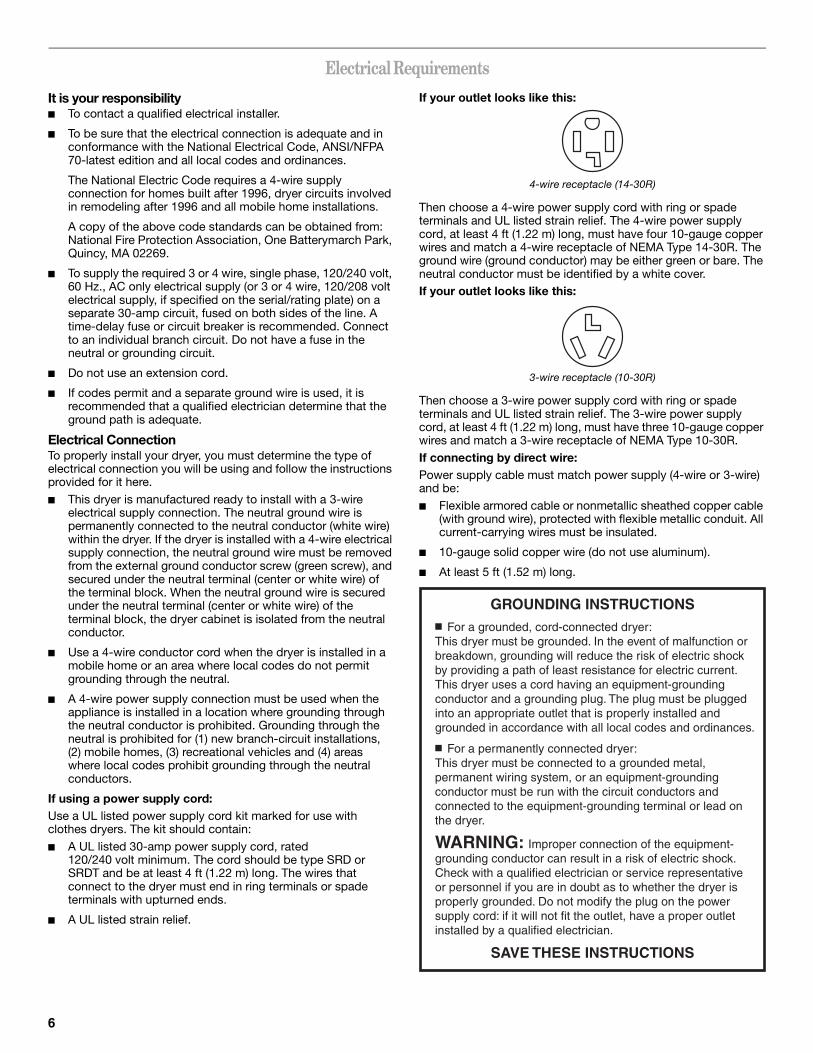
If your outlet looks like this:
4-wire receptacle (14-30R)
Then choose a 4-wire power supply cord with ring or spade terminals and UL listed strain relief. The 4-wire power supply cord, at least 4 ft (1.22 m) long, must have four 10-gauge copper wires and match a 4-wire receptacle of NEMA Type 14-30R. The ground wire (ground conductor) may be either green or bare. The neutral conductor must be identified by a white cover.If your outlet looks like this:
3-wire receptacle (10-30R)
Then choose a 3-wire power supply cord with ring or spade terminals and UL listed strain relief. The 3-wire power supply cord, at least 4 ft (1.22 m) long, must have three 10-gauge copper wires and match a 3-wire receptacle of NEMA Type 10-30R.If connecting by direct wire:Power supply cable must match power supply (4-wire or 3-wire) and be:■ Flexible armored cable or nonmetallic sheathed copper cable
(with ground wire), protected with flexible metallic conduit. All current-carrying wires must be insulated.
■ 10-gauge solid copper wire (do not use aluminum).
■ At least 5 ft (1.52 m) long.
GROUNDING INSTRUCTIONS
SAVE THESE INSTRUCTIONS
■ For a grounded, cord-connected dryer: This dryer must be grounded. In the event of malfunction or breakdown, grounding will reduce the risk of electric shock by providing a path of least resistance for electric current. This dryer uses a cord having an equipment-grounding conductor and a grounding plug. The plug must be plugged into an appropriate outlet that is properly installed and grounded in accordance with all local codes and ordinances.
■ For a permanently connected dryer:This dryer must be connected to a grounded metal, permanent wiring system, or an equipment-grounding conductor must be run with the circuit conductors and connected to the equipment-grounding terminal or lead on the dryer.
WARNING: Improper connection of the equipment-grounding conductor can result in a risk of electric shock.Check with a qualified electrician or service representative or personnel if you are in doubt as to whether the dryer is properly grounded. Do not modify the plug on the power supply cord: if it will not fit the outlet, have a proper outlet installed by a qualified electrician.
7
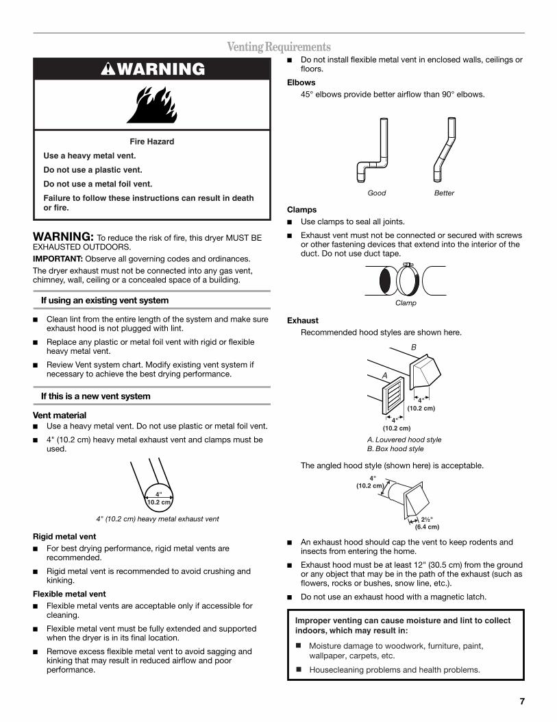
Venting Requirements
WARNING: To reduce the risk of fire, this dryer MUST BE EXHAUSTED OUTDOORS.IMPORTANT: Observe all governing codes and ordinances.The dryer exhaust must not be connected into any gas vent, chimney, wall, ceiling or a concealed space of a building.
If using an existing vent system
■ Clean lint from the entire length of the system and make sure exhaust hood is not plugged with lint.
■ Replace any plastic or metal foil vent with rigid or flexible heavy metal vent.
■ Review Vent system chart. Modify existing vent system if necessary to achieve the best drying performance.
If this is a new vent system
Vent material■ Use a heavy metal vent. Do not use plastic or metal foil vent.
■ 4" (10.2 cm) heavy metal exhaust vent and clamps must be used.
Rigid metal vent■ For best drying performance, rigid metal vents are
recommended.
■ Rigid metal vent is recommended to avoid crushing and kinking.
Flexible metal vent■ Flexible metal vents are acceptable only if accessible for
cleaning.
■ Flexible metal vent must be fully extended and supported when the dryer is in its final location.
■ Remove excess flexible metal vent to avoid sagging and kinking that may result in reduced airflow and poor performance.
■ Do not install flexible metal vent in enclosed walls, ceilings or floors.
Elbows45° elbows provide better airflow than 90° elbows.
Clamps■ Use clamps to seal all joints.
■ Exhaust vent must not be connected or secured with screws or other fastening devices that extend into the interior of the duct. Do not use duct tape.
ExhaustRecommended hood styles are shown here.
The angled hood style (shown here) is acceptable.
■ An exhaust hood should cap the vent to keep rodents and insects from entering the home.
■ Exhaust hood must be at least 12" (30.5 cm) from the ground or any object that may be in the path of the exhaust (such as flowers, rocks or bushes, snow line, etc.).
■ Do not use an exhaust hood with a magnetic latch.
4" (10.2 cm) heavy metal exhaust vent
WARNING
Fire Hazard
Use a heavy metal vent.
Do not use a plastic vent.
Do not use a metal foil vent.
Failure to follow these instructions can result in deathor fire.
4"10.2 cm
Good Better
Clamp
A. Louvered hood styleB. Box hood style
4"(10.2 cm)
4"(10.2 cm)
B
A
4"(10.2 cm)
2½"(6.4 cm)
Improper venting can cause moisture and lint to collect indoors, which may result in:
Moisture damage to woodwork, furniture, paint,
Housecleaning problems and health problems.
wallpaper, carpets, etc.
8
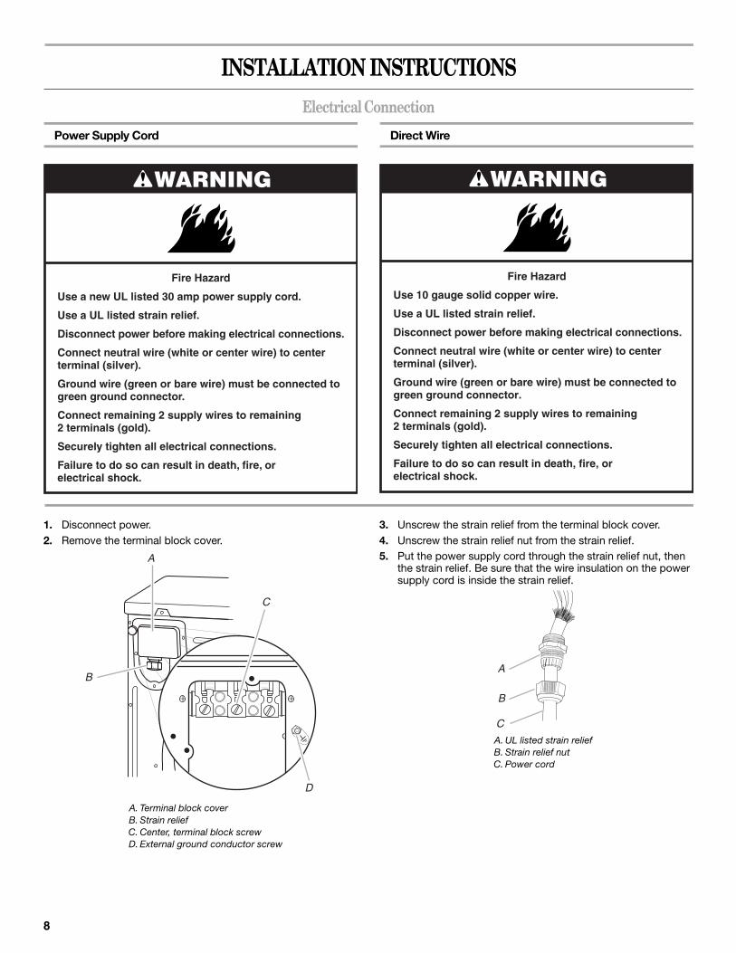
INSTALLATION INSTRUCTIONSElectrical Connection
Power Supply Cord Direct Wire
1. Disconnect power.2. Remove the terminal block cover.
3. Unscrew the strain relief from the terminal block cover.4. Unscrew the strain relief nut from the strain relief.5. Put the power supply cord through the strain relief nut, then
the strain relief. Be sure that the wire insulation on the power supply cord is inside the strain relief.
WARNING
Fire Hazard
Use a new UL listed 30 amp power supply cord.
Use a UL listed strain relief.
Disconnect power before making electrical connections.
Connect neutral wire (white or center wire) to centerterminal (silver).
Ground wire (green or bare wire) must be connected togreen ground connector.
Connect remaining 2 supply wires to remaining2 terminals (gold).
Securely tighten all electrical connections.
Failure to do so can result in death, fire, orelectrical shock.
WARNING
Fire Hazard
Use 10 gauge solid copper wire.
Use a UL listed strain relief.
Disconnect power before making electrical connections.
Connect neutral wire (white or center wire) to centerterminal (silver).
Ground wire (green or bare wire) must be connected togreen ground connector.
Connect remaining 2 supply wires to remaining2 terminals (gold).
Securely tighten all electrical connections.
Failure to do so can result in death, fire, orelectrical shock.
A. Terminal block coverB. Strain reliefC. Center, terminal block screwD. External ground conductor screw
A
D
B
C
A. UL listed strain reliefB. Strain relief nutC. Power cord
B
C
A
9
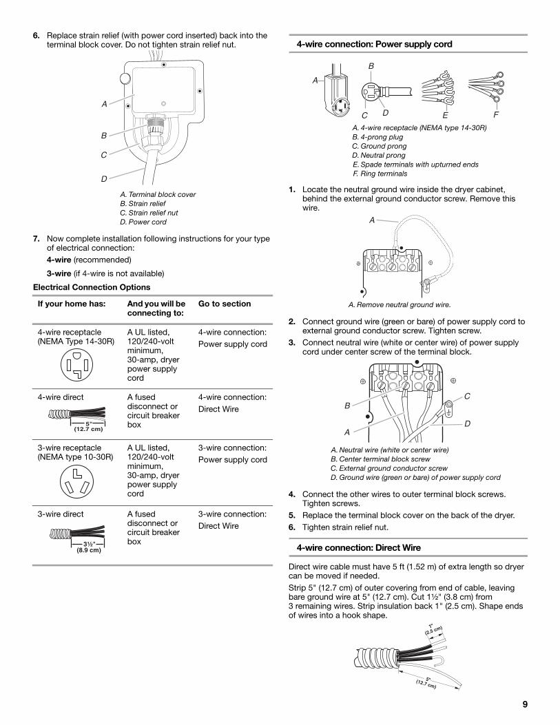
6. Replace strain relief (with power cord inserted) back into the terminal block cover. Do not tighten strain relief nut.
7. Now complete installation following instructions for your type of electrical connection:4-wire (recommended)
3-wire (if 4-wire is not available)
Electrical Connection Options
4-wire connection: Power supply cord
1. Locate the neutral ground wire inside the dryer cabinet, behind the external ground conductor screw. Remove this wire.
2. Connect ground wire (green or bare) of power supply cord to external ground conductor screw. Tighten screw.
3. Connect neutral wire (white or center wire) of power supply cord under center screw of the terminal block.
4. Connect the other wires to outer terminal block screws. Tighten screws.
5. Replace the terminal block cover on the back of the dryer.6. Tighten strain relief nut.
4-wire connection: Direct Wire
Direct wire cable must have 5 ft (1.52 m) of extra length so dryer can be moved if needed. Strip 5" (12.7 cm) of outer covering from end of cable, leaving bare ground wire at 5" (12.7 cm). Cut 1¹⁄₂" (3.8 cm) from 3 remaining wires. Strip insulation back 1" (2.5 cm). Shape ends of wires into a hook shape.
A. Terminal block coverB. Strain reliefC. Strain relief nutD. Power cord
If your home has: And you will be connecting to:
Go to section
4-wire receptacle(NEMA Type 14-30R)
A UL listed, 120/240-volt minimum, 30-amp, dryer power supply cord
4-wire connection:Power supply cord
4-wire direct A fused disconnect or circuit breaker box
4-wire connection:Direct Wire
3-wire receptacle(NEMA type 10-30R)
A UL listed, 120/240-volt minimum, 30-amp, dryer power supply cord
3-wire connection:Power supply cord
3-wire direct A fused disconnect or circuit breaker box
3-wire connection:Direct Wire
B
A
C
D
(12.7 cm)5"
(8.9 cm)3¹⁄₂"
A. 4-wire receptacle (NEMA type 14-30R)B. 4-prong plugC. Ground prongD. Neutral prongE. Spade terminals with upturned endsF. Ring terminals
A. Remove neutral ground wire.
A. Neutral wire (white or center wire) B. Center terminal block screw C. External ground conductor screwD. Ground wire (green or bare) of power supply cord
A
B
C D E F
A
BC
AD
10
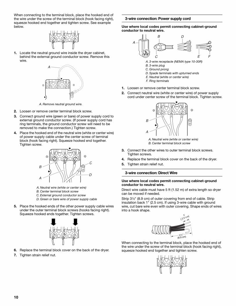
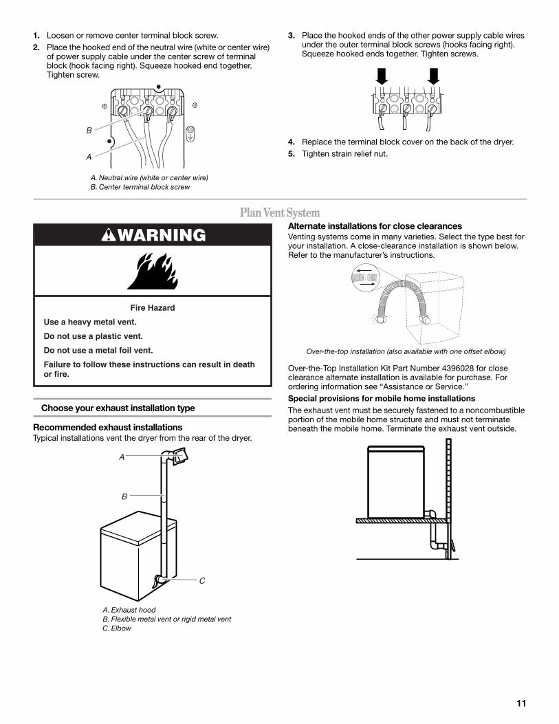
When connecting to the terminal block, place the hooked end of the wire under the screw of the terminal block (hook facing right), squeeze hooked end together and tighten screw. See example below.
1. Locate the neutral ground wire inside the dryer cabinet, behind the external ground conductor screw. Remove this wire.
2. Loosen or remove center terminal block screw.3. Connect ground wire (green or bare) of power supply cord to
external ground conductor screw. (If power supply cord has ring terminals, the ground conductor screw will need to be removed to make the connection.) Tighten screw.
4. Place the hooked end of the neutral wire (white or center wire) of power supply cable under the center screw of terminal block (hook facing right). Squeeze hooked end together. Tighten screw.
5. Place the hooked ends of the other power supply cable wires under the outer terminal block screws (hooks facing right). Squeeze hooked ends together. Tighten screws.
6. Replace the terminal block cover on the back of the dryer.7. Tighten strain relief nut.
3-wire connection: Power supply cord
Use where local codes permit connecting cabinet-ground conductor to neutral wire.
1. Loosen or remove center terminal block screw.2. Connect neutral wire (white or center wire) of power supply
cord under center screw of the terminal block. Tighten screw.
3. Connect the other wires to outer terminal block screws. Tighten screws.
4. Replace the terminal block cover on the back of the dryer.5. Tighten strain relief nut.
3-wire connection: Direct Wire
Use where local codes permit connecting cabinet-ground conductor to neutral wire.Direct wire cable must have 5 ft (1.52 m) of extra length so dryer can be moved if needed. Strip 3¹⁄₂" (8.9 cm) of outer covering from end of cable. Strip insulation back 1" (2.5 cm). If using 3-wire cable with ground wire, cut bare wire even with outer covering. Shape ends of wires into a hook shape.
When connecting to the terminal block, place the hooked end of the wire under the screw of the terminal block (hook facing right), squeeze hooked end together and tighten screw.
A. Remove neutral ground wire.
A. Neutral wire (white or center wire)B. Center terminal block screw C. External ground conductor screwD. Green or bare wire of power supply cable
A
BC
AD
A. 3-wire receptacle (NEMA type 10-30R)B. 3-wire plugC. Ground prongD. Spade terminals with upturned endsE. Neutral (white or center wire)F. Ring terminals
A. Neutral wire (white or center wire) B. Center terminal block screw
A
B D
C FE
B
A
1
11
1. Loosen or remove center terminal block screw.2. Place the hooked end of the neutral wire (white or center wire)
of power supply cable under the center screw of terminal block (hook facing right). Squeeze hooked end together. Tighten screw.
3. Place the hooked ends of the other power supply cable wires under the outer terminal block screws (hooks facing right). Squeeze hooked ends together. Tighten screws.
4. Replace the terminal block cover on the back of the dryer.5. Tighten strain relief nut.
Plan Vent System
Choose your exhaust installation type
Recommended exhaust installationsTypical installations vent the dryer from the rear of the dryer.
Alternate installations for close clearancesVenting systems come in many varieties. Select the type best for your installation. A close-clearance installation is shown below. Refer to the manufacturer’s instructions.
Over-the-Top Installation Kit Part Number 4396028 for close clearance alternate installation is available for purchase. For ordering information see “Assistance or Service.”Special provisions for mobile home installationsThe exhaust vent must be securely fastened to a noncombustible portion of the mobile home structure and must not terminate beneath the mobile home. Terminate the exhaust vent outside.
A. Neutral wire (white or center wire)B. Center terminal block screw
B
A
A. Exhaust hoodB. Flexible metal vent or rigid metal ventC. Elbow
WARNING
Fire Hazard
Use a heavy metal vent.
Do not use a plastic vent.
Do not use a metal foil vent.
Failure to follow these instructions can result in deathor fire.
A
B
C
Over-the-top installation (also available with one offset elbow)
12
Determine vent path
■ Select the route that will provide the straightest and most direct path outdoors.
■ Plan the installation to use the fewest number of elbows and turns.
■ When using elbows or making turns, allow as much room as possible.
■ Bend vent gradually to avoid kinking.
■ Use the fewest 90° turns possible.
Determine vent length and elbows needed for best drying performance
■ Use the following Vent system chart to determine type of vent material and hood combinations acceptable to use.
NOTE: Do not use vent runs longer than those specified in the Vent system chart. Exhaust systems longer than those specified will:
■ Shorten the life of the dryer.
■ Reduce performance, resulting in longer drying times and increased energy usage.
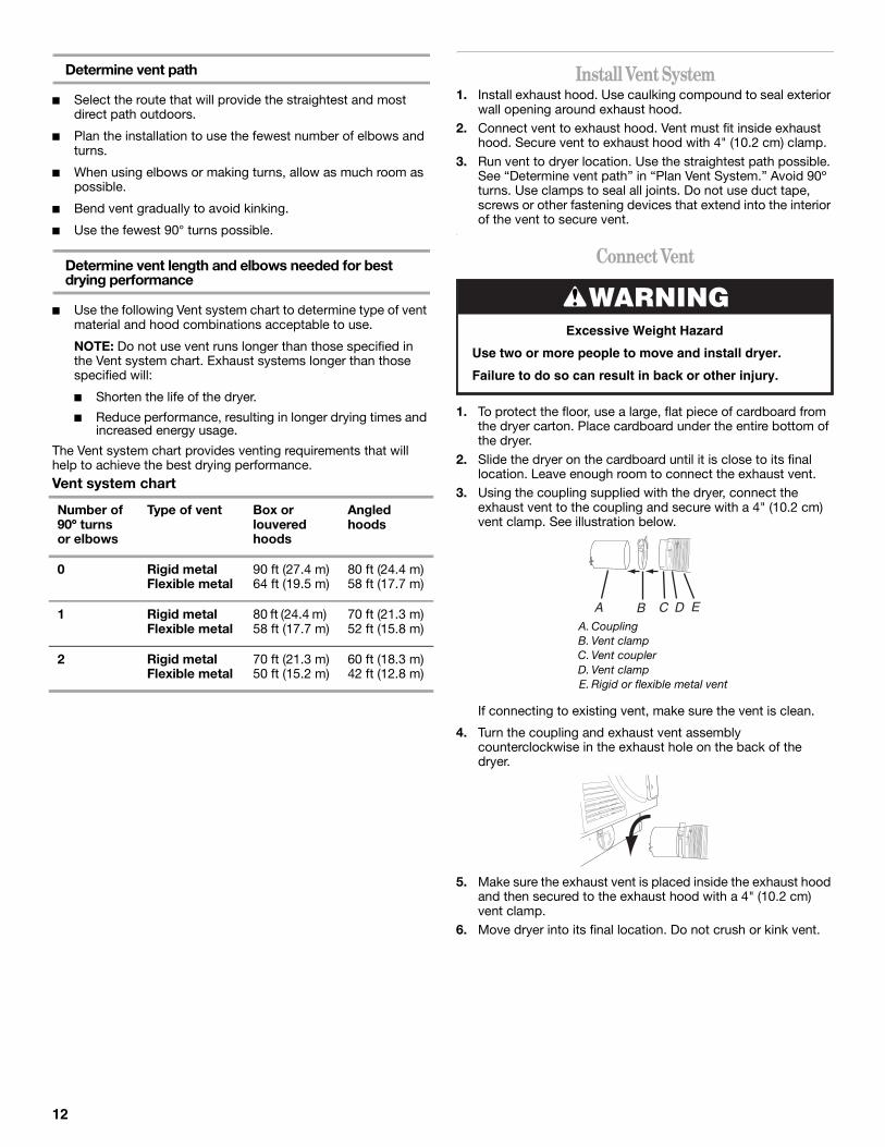
The Vent system chart provides venting requirements that will help to achieve the best drying performance. Vent system chart
Install Vent System1. Install exhaust hood. Use caulking compound to seal exterior
wall opening around exhaust hood.2. Connect vent to exhaust hood. Vent must fit inside exhaust
hood. Secure vent to exhaust hood with 4" (10.2 cm) clamp.3. Run vent to dryer location. Use the straightest path possible.
See “Determine vent path” in “Plan Vent System.” Avoid 90º turns. Use clamps to seal all joints. Do not use duct tape, screws or other fastening devices that extend into the interior of the vent to secure vent.
Connect Vent
1. To protect the floor, use a large, flat piece of cardboard from the dryer carton. Place cardboard under the entire bottom of the dryer.
2. Slide the dryer on the cardboard until it is close to its final location. Leave enough room to connect the exhaust vent.
3. Using the coupling supplied with the dryer, connect the exhaust vent to the coupling and secure with a 4" (10.2 cm) vent clamp. See illustration below.
If connecting to existing vent, make sure the vent is clean.
4. Turn the coupling and exhaust vent assembly counterclockwise in the exhaust hole on the back of the dryer.
5. Make sure the exhaust vent is placed inside the exhaust hood and then secured to the exhaust hood with a 4" (10.2 cm) vent clamp.
6. Move dryer into its final location. Do not crush or kink vent.
Number of 90º turns or elbows
Type of vent Box or louvered hoods
Angledhoods
0 Rigid metalFlexible metal
90 ft (27.4 m)64 ft (19.5 m)
80 ft (24.4 m)58 ft (17.7 m)
1 Rigid metalFlexible metal
80 ft (24.4 m) 58 ft (17.7 m)
70 ft (21.3 m)52 ft (15.8 m)
2 Rigid metalFlexible metal
70 ft (21.3 m)50 ft (15.2 m)
60 ft (18.3 m)42 ft (12.8 m)
A. CouplingB. Vent clampC. Vent couplerD. Vent clampE. Rigid or flexible metal vent
WARNINGExcessive Weight Hazard
Use two or more people to move and install dryer.
Failure to do so can result in back or other injury.
A B C D E
13
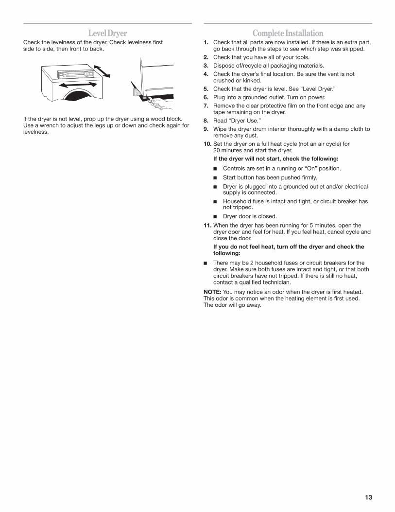
Level DryerCheck the levelness of the dryer. Check levelness first side to side, then front to back.
If the dryer is not level, prop up the dryer using a wood block. Use a wrench to adjust the legs up or down and check again for levelness.
Complete Installation1. Check that all parts are now installed. If there is an extra part,
go back through the steps to see which step was skipped.2. Check that you have all of your tools.3. Dispose of/recycle all packaging materials.
4. Check the dryer’s final location. Be sure the vent is not crushed or kinked.
5. Check that the dryer is level. See “Level Dryer.”
6. Plug into a grounded outlet. Turn on power.7. Remove the clear protective film on the front edge and any
tape remaining on the dryer.
8. Read “Dryer Use.”9. Wipe the dryer drum interior thoroughly with a damp cloth to
remove any dust.
10. Set the dryer on a full heat cycle (not an air cycle) for 20 minutes and start the dryer.If the dryer will not start, check the following:
Controls are set in a running or “On” position.
Start button has been pushed firmly.
Dryer is plugged into a grounded outlet and/or electrical supply is connected.
Household fuse is intact and tight, or circuit breaker has not tripped.
Dryer door is closed.
11. When the dryer has been running for 5 minutes, open the dryer door and feel for heat. If you feel heat, cancel cycle and close the door.
If you do not feel heat, turn off the dryer and check the following:
There may be 2 household fuses or circuit breakers for the dryer. Make sure both fuses are intact and tight, or that both circuit breakers have not tripped. If there is still no heat, contact a qualified technician.
NOTE: You may notice an odor when the dryer is first heated.This odor is common when the heating element is first used. The odor will go away.
14
DRYER USE
Starting Your Dryer
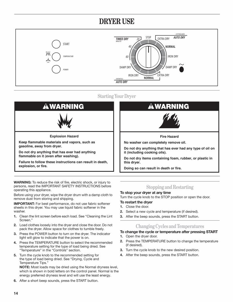
WARNING: To reduce the risk of fire, electric shock, or injury to persons, read the IMPORTANT SAFETY INSTRUCTIONS before operating this appliance.Before using your dryer, wipe the dryer drum with a damp cloth to remove dust from storing and shipping.IMPORTANT: For best performance, do not use fabric softener sheets in this dryer. You may use liquid fabric softener in the washer.1. Clean the lint screen before each load. See “Cleaning the Lint
Screen.”2. Load clothes loosely into the dryer and close the door. Do not
pack the dryer. Allow space for clothes to tumble freely.3. Press the POWER button to turn on the dryer. The indicator
light will glow to indicate that the power is on.4. Press the TEMPERATURE button to select the recommended
temperature setting for the type of load being dried. See “Temperature” in the “Controls” section.
5. Turn the cycle knob to the recommended setting forthe type of load being dried. See “Drying, Cycle and Temperature Tips.”NOTE: Most loads may be dried using the Normal dryness level, which is shown in bold letters on the control panel. Normal is the energy preferred dryness level and will use the least energy.
6. After a short beep sounds, press the START button.
Stopping and RestartingTo stop your dryer at any timeTurn the cycle knob to the STOP position or open the door.
To restart the dryer1. Close the door.2. Select a new cycle and temperature (if desired).3. After the beep sounds, press the START button.
Changing Cycles and TemperaturesTo change the cycle or temperature after pressing START1. Open the dryer door.2. Press the TEMPERATURE button to change the temperature
(if desired).3. Turn the cycle knob to the new desired position.4. After the beep sounds, press the START button.
WARNING
Explosion HazardKeep flammable materials and vapors, such asgasoline, away from dryer.Do not dry anything that has ever had anythingflammable on it (even after washing).Failure to follow these instructions can result in death,explosion, or fire.
WARNING
Fire HazardNo washer can completely remove oil.Do not dry anything that has ever had any type of oil on it (including cooking oils).Do not dry items containing foam, rubber, or plastic in this dryer.Doing so can result in death or fire.
15
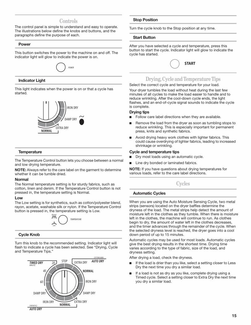
ControlsThe control panel is simple to understand and easy to operate. The illustrations below define the knobs and buttons, and the paragraphs define the purpose of each.
Power
This button switches the power to the machine on and off. The indicator light will glow to indicate the power is on.
Indicator Light
This light indicates when the power is on or that a cycle has started.
Temperature
The Temperature Control button lets you choose between a normal and low drying temperature.
NOTE: Always refer to the care label on the garment to determine whether it can be tumble dried.
NormalThe Normal temperature setting is for sturdy fabrics, such as cotton, linen and denim. If the Temperature Control button is not pressed in, the temperature setting is Normal.
LowThe Low setting is for synthetics, such as cotton/polyester blend, rayon, acetate, washable silk or nylon. If the Temperature Control button is pressed in, the temperature setting is Low.
Cycle Knob
Turn this knob to the recommended setting. Indicator light will flash to indicate a cycle has been selected. See “Drying, Cycle and Temperature Tips.”
Stop Position
Turn the cycle knob to the Stop position at any time.
Start Button
After you have selected a cycle and temperature, press this button to start the cycle. Indicator light will glow to indicate the cycle has started.
Drying, Cycle and Temperature TipsSelect the correct cycle and temperature for your load.
Your dryer tumbles the load without heat during the last few minutes of all cycles to make the load easier to handle and to reduce wrinkling. After the cool-down cycle ends, the light flashes, and an end-of-cycle signal sounds to indicate the cycle is complete.
Drying tipsFollow care label directions when they are available.
Remove the load from the dryer as soon as tumbling stops to reduce wrinkling. This is especially important for permanent press, knits and synthetic fabrics.
Avoid drying heavy work clothes with lighter fabrics. This could cause overdrying of lighter fabrics, leading to increased shrinkage or wrinkling.
Cycle and temperature tips Dry most loads using an automatic cycle.
Line dry bonded or laminated fabrics.
NOTE: If you have questions about drying temperatures for various loads, refer to the care label directions.
Cycles
Automatic Cycles
When you are using the Auto Moisture Sensing Cycle, two metal strips (sensors) located on the dryer baffles determine the dryness of the load. The metal strips help detect the amount of moisture left in the clothes as they tumble. When there is moisture left in the clothes, the machine will continue to run. As clothes begin to dry, the amount of water left in the clothes decreases, and the timer advances through the remainder of the cycle. When the selected dryness level is reached, the dryer goes into a cool down period of up to 15 minutes. Automatic cycles may be used for most loads. Automatic cycles give the best drying results in the shortest time. Drying time varies according to the type of fabric, size of the load, and dryness setting.After drying a load, check the dryness.
If the load is drier than you like, select a setting closer to Less Dry the next time you dry a similar load.
If a load is not as dry as you like, complete drying using a Timed cycle. Select a setting closer to Extra Dry the next time you dry a similar load.
16
See following table for recommended cycles and temperature settings.
Timed Dry
Use this cycle to get up to 60 minutes of heated drying time or to complete drying if items are still damp after the automatic cycle. Timed Dry is also useful for:
Heavyweight items and work clothes that require a long drying time.
Lightweight items, such as lingerie, blouses and knits that require a short drying time.
See following table for recommended cycles and temperature settings.
End of Cycle Signal
The dryer sounds a signal to let you know when the cycle is complete. The signal is not adjustable and cannot be turned off. The signal is helpful when you are drying permanent press, synthetics, and other items that should be removed promptly at the end of the cycle.
Anti-Wrinkle
Anti-Wrinkle helps smooth out wrinkles that form when clothes are not removed promptly at the end of a cycle. Anti-Wrinkle tumbles the load every minute until the cycle knob is set to the Stop position or the dryer door is opened.During Anti-Wrinkle, the End of Cycle Signal will sound until the cycle knob is set to the Stop position or the dryer door is opened.
DRYER CARE
Cleaning the Dryer LocationKeep dryer area clear and free from items that would obstruct the flow of combustion and ventilation air.
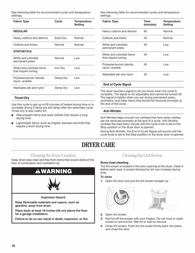
Cleaning the Lint ScreenEvery load cleaningThe lint screen is located in the door opening of the dryer. Clean it before each load. A screen blocked by lint can increase drying time.To clean1. Open the door and pull the lint screen straight up.
2. Open lint screen.3. Roll lint off the screen with your fingers. Do not rinse or wash
screen to remove lint. Wet lint is hard to remove.
4. Close lint screen. Push the lint screen firmly back into place and close the door.
Fabric Type Cycle Temperature Setting
REGULAR
Heavy cottons and denims Extra Dry Normal
Cottons and linens Normal Normal
SYNTHETICS
White and colorfast permanent press
Normal Low
White and colorfast items that require ironing
Iron Dry Low
Polyester/acrylic blends, rayon, acetate
Damp Dry Low
Washable silk and nylon Damp Dry Low
Fabric Type Time (minutes)
Temperature Setting
Heavy cottons and denims 60 Normal
Cottons and linens 40 Normal
White and colorfast permanent press
40 Low
White and colorfast items that require ironing
40 Low
Polyester/acrylic blends, rayon, acetate
40 Low
Washable silk and nylon 40 Low
WARNING
Explosion Hazard
Keep flammable materials and vapors, such asgasoline, away from dryer.
Place dryer at least 18 inches (46 cm) above the floorfor a garage installation.
Failure to do so can result in death, explosion, or fire.
17
IMPORTANT:■ Do not run the dryer with the lint screen loose, damaged,
blocked or missing. Doing so can cause overheating and damage to both the dryer and fabrics.
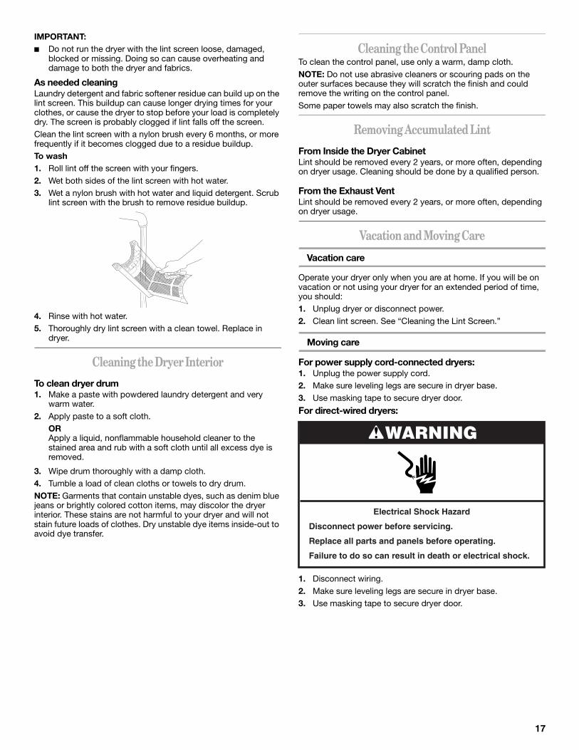
As needed cleaningLaundry detergent and fabric softener residue can build up on the lint screen. This buildup can cause longer drying times for your clothes, or cause the dryer to stop before your load is completely dry. The screen is probably clogged if lint falls off the screen. Clean the lint screen with a nylon brush every 6 months, or more frequently if it becomes clogged due to a residue buildup.To wash1. Roll lint off the screen with your fingers.2. Wet both sides of the lint screen with hot water.3. Wet a nylon brush with hot water and liquid detergent. Scrub
lint screen with the brush to remove residue buildup.
4. Rinse with hot water.5. Thoroughly dry lint screen with a clean towel. Replace in
dryer.
Cleaning the Dryer InteriorTo clean dryer drum1. Make a paste with powdered laundry detergent and very
warm water.2. Apply paste to a soft cloth.
ORApply a liquid, nonflammable household cleaner to the stained area and rub with a soft cloth until all excess dye is removed.
3. Wipe drum thoroughly with a damp cloth.4. Tumble a load of clean cloths or towels to dry drum.NOTE: Garments that contain unstable dyes, such as denim blue jeans or brightly colored cotton items, may discolor the dryer interior. These stains are not harmful to your dryer and will not stain future loads of clothes. Dry unstable dye items inside-out to avoid dye transfer.
Cleaning the Control PanelTo clean the control panel, use only a warm, damp cloth.NOTE: Do not use abrasive cleaners or scouring pads on the outer surfaces because they will scratch the finish and could remove the writing on the control panel.Some paper towels may also scratch the finish.
Removing Accumulated LintFrom Inside the Dryer CabinetLint should be removed every 2 years, or more often, depending on dryer usage. Cleaning should be done by a qualified person.
From the Exhaust VentLint should be removed every 2 years, or more often, depending on dryer usage.
Vacation and Moving Care
Vacation care
Operate your dryer only when you are at home. If you will be on vacation or not using your dryer for an extended period of time, you should:1. Unplug dryer or disconnect power.2. Clean lint screen. See “Cleaning the Lint Screen.”
Moving care
For power supply cord-connected dryers:1. Unplug the power supply cord. 2. Make sure leveling legs are secure in dryer base.3. Use masking tape to secure dryer door.
For direct-wired dryers:
1. Disconnect wiring.2. Make sure leveling legs are secure in dryer base.3. Use masking tape to secure dryer door.
WARNING
Electrical Shock Hazard
Disconnect power before servicing.
Replace all parts and panels before operating.
Failure to do so can result in death or electrical shock.
18
TROUBLESHOOTINGFirst try the solutions suggested here and possibly avoid the cost of a service call...
Dryer Operation
Dryer will not run
■ Has a household fuse blown, or has a circuit breaker tripped? There may be 2 fuses or circuit breakers for the dryer. Make sure both fuses are intact and tight, or that both circuit breakers have not tripped. Replace the fuse or reset the circuit breaker. If the problem continues, call an electrician.
■ Is the correct power supply available?Electric dryers require 240-volt power supply. Check with a qualified electrician.
■ Was a regular fuse used? Use a time-delay fuse.
■ Is the dryer door firmly closed?
■ Was the Start button firmly pressed?
■ Is the motor running but the drum isn’t turning?The belt may be broken. Call for service.
■ Is the indicator light glowing? If not, press the POWER button.
No heat
■ Has a household fuse blown, or has a circuit breaker tripped? Electric dryers use 2 household fuses or circuit breakers. The drum may be turning, but you may not have heat. Replace the fuse or reset the circuit breaker. If the problem continues, call an electrician.
Unusual sounds
■ Has the dryer had a period of non-use? If the dryer hasn’t been used for a while, there may be a thumping sound during the first few minutes of operation.
■ Is a coin, button or paper clip caught between the drum and front or rear of the dryer? Check the front and rear edges of the drum for small objects. Clean out pockets before laundering.
■ Are the four legs installed, and is the dryer level front to back and side to side? The dryer may vibrate if not properly installed. See “Installation Instructions.”
■ Is the clothing knotted or balled up? When balled up, the load will bounce, causing the dryer to vibrate. Separate the load items and restart the dryer.
Dryer Results
Clothes are not drying satisfactorily, drying times are too long, or load is too hot
NOTE: The compact dryer operates at a lower wattage. Expect longer drying times.■ Is the lint screen clogged with lint?
Lint screen should be cleaned before each load.
■ Is the exhaust vent or outside exhaust hood clogged with lint, restricting air movement? Run the dryer for 5-10 minutes. Hold your hand under the outside exhaust hood to check air movement. If you do not feel air movement, clean exhaust system of lint or replace exhaust vent with heavy metal or flexible metal vent. See “Installation Instructions.”
■ Is the exhaust vent the correct length? Check that the exhaust vent is not too long or has too many turns. Long venting will increase drying times. See “Installation Instructions.”
■ Is the exhaust vent diameter the correct size? Use 4" (10.2 cm) diameter vent material.
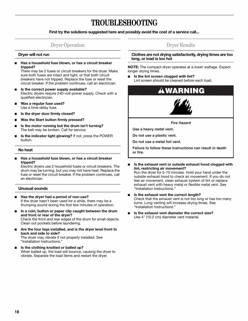
WARNING
Fire Hazard
Use a heavy metal vent.
Do not use a plastic vent.
Do not use a metal foil vent.
Failure to follow these instructions can result in deathor fire.
19
■ Is the dryer located in a room with temperature below45ºF (7ºC)? Proper operation of dryer cycles requires temperatures above 45ºF (7ºC).
■ Is the dryer located in a closet? Closet doors must have ventilation openings at the top and bottom of the door. The rear of the dryer requires a minimum of 5½" (14 cm) of airspace, and 1" (2.5 cm) is recommended for the sides and front of the dryer. See “Installation Instructions.”
■ Is the load too large and heavy to dry quickly? Separate the load to tumble freely.
Cycle time too short
■ Is the automatic cycle ending early? The load may not be contacting the sensor strips. Level the dryer.
Change the dryness level setting on Automatic Cycles. Increasing or decreasing the dryness level will change the amount of drying time in a cycle.
Lint on load
■ Is the lint screen clogged?Lint screen should be cleaned before each load.
Stains on load or drum
■ Drum stains are caused by dyes in clothing (usually blue jeans). This will not transfer to other clothing.
Loads are wrinkled
■ Was the load removed from dryer at the end of the cycle?
■ Was the dryer overloaded? Dry smaller loads that can tumble freely.
Odors
■ Have you recently been painting, staining or varnishing in the area where your dryer is located?If so, ventilate the area. When the odors or fumes are gone from the area, rewash and dry the clothing.
■ Is the dryer being used for the first time?The new electric heating element may have an odor. The odor will be gone after the first cycle.
ASSISTANCE OR SERVICEBefore calling for assistance or service, please check “Troubleshooting.” It may save you the cost of a service call. If you still need help, follow the instructions below.When calling, please know the purchase date and the complete model and serial number of your appliance. This information will help us to better respond to your request.
If you need replacement partsIf you need to order replacement parts, we recommend that you use only FSP® replacement parts. FSP® replacement parts will fit right and work right because they are made with the same precision used to build every new WHIRLPOOL® appliance. To locate FSP® replacement parts in your area, call us or your nearest Whirlpool designated service center.
In the U.S.A.Call the Whirlpool Customer eXperience Center toll free: 1-800-253-1301.
Our consultants provide assistance with:■ Features and specifications on our full line of appliances.
■ Installation information.
■ Use and maintenance procedures.
■ Accessory and repair parts sales.
■ Specialized customer assistance (Spanish speaking, hearing impaired, limited vision, etc.).
■ Referrals to local dealers, repair parts distributors and service companies. Whirlpool designated service technicians are trained to fulfill the product warranty and provide after-warranty service, anywhere in the United States.
To locate the Whirlpool designated service company in your area, you can also look in your telephone directory Yellow Pages.
For further assistanceIf you need further assistance, you can write to Whirlpool Corporation with any questions or concerns at:
Whirlpool Brand Home AppliancesCustomer eXperience Center553 Benson RoadBenton Harbor, MI 49022-2692
Please include a daytime phone number in your correspondence.
WARNING
Explosion Hazard
Keep flammable materials and vapors, such asgasoline, away from dryer.
Place dryer at least 18 inches (46 cm) above the floorfor a garage installation.
Failure to do so can result in death, explosion, or fire.
WARNINGExcessive Weight Hazard
Use two or more people to move and install dryer.
Failure to do so can result in back or other injury.
W10189310B© 2008 Whirlpool CorporationAll rights reserved ® Registered Trademark/TM Trademark of Whirlpool U S A
4/08Printed in Italy
WHIRLPOOL CORPORATION MAJOR APPLIANCE WARRANTYONE YEAR LIMITED WARRANTY
For one year from the date of purchase, when this major appliance is operated and maintained according to instructions attached to or furnished with the product, Whirlpool Corporation or Whirlpool Canada LP (hereafter “Whirlpool”) will pay for Factory Specified Parts and repair labor to correct defects in materials or workmanship. Service must be provided by a Whirlpool designated service company. This limited warranty applies only when the major appliance is used in the country in which it was purchased.
ITEMS WHIRLPOOL WILL NOT PAY FOR1. Service calls to correct the installation of your major appliance, to instruct you how to use your major appliance, to replace or repair
house fuses or to correct house wiring or plumbing. 2. Service calls to repair or replace appliance light bulbs, air filters or water filters. Those consumable parts are excluded from warranty
coverage.3. Repairs when your major appliance is used for other than normal, single-family household use.4. Damage resulting from accident, alteration, misuse, abuse, fire, flood, acts of God, improper installation, installation not in
accordance with electrical or plumbing codes, or use of products not approved by Whirlpool.5. Any food loss due to refrigerator or freezer product failures.6. Replacement parts or repair labor costs for units operated outside the United States or Canada.7. Pickup and delivery. This major appliance is designed to be repaired in the home.8. Repairs to parts or systems resulting from unauthorized modifications made to the appliance.9. Expenses for travel and transportation for product service in remote locations.10. The removal and reinstallation of your appliance if it is installed in an inaccessible location or is not installed in accordance with
published installation instructions.11. Replacement parts or repair labor costs when the major appliance is used in a country other than the country in which it was
purchased.
DISCLAIMER OF IMPLIED WARRANTIES; LIMITATION OF REMEDIESCUSTOMER'S SOLE AND EXCLUSIVE REMEDY UNDER THIS LIMITED WARRANTY SHALL BE PRODUCT REPAIR AS PROVIDED HEREIN. IMPLIED WARRANTIES, INCLUDING WARRANTIES OF MERCHANTABILITY OR FITNESS FOR A PARTICULAR PURPOSE, ARE LIMITED TO ONE YEAR OR THE SHORTEST PERIOD ALLOWED BY LAW. WHIRLPOOL SHALL NOT BE LIABLE FOR INCIDENTAL OR CONSEQUENTIAL DAMAGES. SOME STATES AND PROVINCES DO NOT ALLOW THE EXCLUSION OR LIMITATION OF INCIDENTAL OR CONSEQUENTIAL DAMAGES, OR LIMITATIONS ON THE DURATION OF IMPLIED WARRANTIES OF MERCHANTABILITY OR FITNESS, SO THESE EXCLUSIONS OR LIMITATIONS MAY NOT APPLY TO YOU. THIS WARRANTY GIVES YOU SPECIFIC LEGAL RIGHTS AND YOU MAY ALSO HAVE OTHER RIGHTS, WHICH VARY FROM STATE TO STATE OR PROVINCE TO PROVINCE.
Outside the 50 United States and Canada, this warranty does not apply. Contact your authorized Whirlpool dealer to determine if another warranty applies.If you need service, first see the “Troubleshooting” section of the Use & Care Guide. After checking “Troubleshooting,” additional help can be found by checking the “Assistance or Service” section or by calling Whirlpool. In the U.S.A., call 1-800-253-1301. In Canada, call 1-800-807-6777. 12/05
Keep this book and your sales slip together for future reference. You must provide proof of purchase or installation date for in-warranty service.Write down the following information about your major appliance to better help you obtain assistance or service if you ever need it. You will need to know your complete model number and serial number. You can find this information on the model and serial number label located on the product.
Dealer name____________________________________________________
Address ________________________________________________________
Phone number__________________________________________________
Model number __________________________________________________
Serial number __________________________________________________
Purchase date __________________________________________________


![Whirlpool Front Load Washer Instructions IFU[1]](https://static.fdocuments.net/doc/165x107/54faef7f4a79590b398b4ff0/whirlpool-front-load-washer-instructions-ifu1.jpg)