When fitting this product, the following ... - futronix.com · PROGRAMMABLE LIGHTING CONTROLLER...
64
Transcript of When fitting this product, the following ... - futronix.com · PROGRAMMABLE LIGHTING CONTROLLER...


This User’ s Guide & Technical Reference is to help Qualified Electrical Engineers install and set upFutronix Dimming Equipment. This guide is split into 2 sections; the first section covers fitting yourdimmer, and the second explains how to program your dimmer. If you are the INSTALLER OR ELECTRICIANthen please leave this guide behind for the customer.
Every effort has been made to ensure that the information in this manual is accurate. Futronix is notresponsible for printing or clerical errors. Information in this document is subject to change without notice anddoes not represent a commitment on the part of Futronix.
Futronix provides this manual “As is” without warranty of any kind, either express or implied, including but notlimited to implied warranties or conditions of merchantability or fitness for a particular purpose. In no event shallFutronix be liable for any loss or profits, loss of business, losses arising from the loss of lighting, interruptionof business, or for indirect, special, incidental,or consequential damages of any kind, even if Futronix has been advised of the possibility of suchdamages arising from any defect or error in this manual or any product. Specifications are subjectto change without any notice or obligation on the part of the manufacturer.
When fitting this product, the following should be observed:
This product must be fitted by a qualified electrician.Do not overload the dimmer. You must check the wattage of the lamps and how many there areon each circuit. The load on each circuit must be less than the wattage described for eachchannel on the dimmer. The TOTAL wattage of all the lights connected to any one dimmer mustnot exceed the TOTAL rating indicated.
The P100 is designed for domestic use and is not considered suitable for commercialapplications.
Do not insulation test (Megger) any circuits connected to this product.
USER NOTICE
Futronix 1A

PROGRAMMABLE LIGHTING CONTROLLER INSTALLATION GUIDE FOR
P100, P400 & P800
Thank you for purchasing this programmable lighting controller.
At Futronix we dedicate ourselves to the manufacture of high qualityproducts. This unit is a sophisticated all digital dimmer incorporatingFutronix’s patented ‘dimmer on a chip’ technology.
Futronix dimmers are designed to be easy to install, versatile and operatereliably for many years. We are grateful that you have chosen thisproduct and would welcome any comments that you may have.
Futronix House143 Croydon Road,CaterhamSurrey, UKCR3 6PFTel: 01883 373 3333Website: http//www.futronix.comTechnical support: [email protected]
USAFreephone: 1-8888-033-604Call for state distributorEmail: [email protected]

Futronix
Contents List
Important installation information & warnings - MUST BE READ......................
Introduction - Thank You...................................................................................
P100, P400 & P800 description........................................................................
Dimmer ratings and fuse information................................................................
Types of lamp that are dimmable or switchable................................................
Transformers low voltage - suitable types.........................................................
Dimmer mounting location & wall mounting boxes...........................................
Wiring diagrams...............................................................................................
Dimmer load capacities & connections.............................................................
Connecting 12v transformers............................................................................
Programming DEFAULT FEATURES...............................................................
How to program lighting levels, fade rates (CUSTOMER SETTINGS)..............
Remote control.................................................................................................
Flow charts for CUSTOMER SETTINGS..........................................................
Programming CIRCUIT PARAMETERS...........................................................
Programming the Timer....................................................................................
Programming the Timer to select scenes..........................................................
Sleep Timer / Exit delay....................................................................................
Autosequence and display................................................................................
P400 / P800 special features............................................................................
Interconnecting dimmers and setting up zones.................................................
Switch panel outstations...................................................................................
Switch panels - programming...........................................................................
Fault Finding.....................................................................................................
Glossary of terms.............................................................................................
1A
1
3
7
8
9
10
12
16
17
19
21
22
23
28
31
33
38
40
43
46
50
53
56
59
2

Futronix
The P100 DIMMERSwitch functionality
The ON button will turn allthe circuits on to 75% offull brightness with 0.5
second fade.
The OFF button willturn all the circuits
OFF at fade rate setby the user.
The UP scene scrollkey will sequencethrough the scene
numbers from 1-20.Once the correct
scene is shown onthe display, releasingthe button will let the
scene fade in.
The DOWN scenescroll key will
sequence downthrough the scene
numbers.Once the correct
scene is shown onthe display, releasing
the button will letthe scene fade in.
This window is acombined display and
Infra-red receiver.The display in normal
mode shows thescene selected.
In program mode itshows the relevant
programminginformation.
3
Futronix
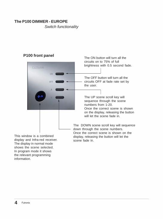
The P100 DIMMER - EUROPE Switch functionality
The ON button will turn all thecircuits on to 75% of fullbrightness with 0.5 second fade.
The OFF button will turn all thecircuits OFF at fade rate set bythe user.
The UP scene scroll key willsequence through the scenenumbers from 1-20.Once the correct scene is shownon the display, releasing the buttonwill let the scene fade in.
The DOWN scene scroll key will sequencedown through the scene numbers.Once the correct scene is shown on thedisplay, releasing the button will let thescene fade in.
This window is a combineddisplay and Infra-red receiver.The display in normal modeshows the scene selected.In program mode it showsthe relevant programminginformation.
P100 front panel
4

Futronix
P400 DIMMERSwitch functionality
P400 front panel
This window is a combined display andInfra-red receiver. The display in normal
mode shows the scene selected. Inprogram mode it shows the relevant
programming information.
The ON button will turn all thecircuits to 75% of full brightness
with a 0.5 second fade.
The OFF button will turn all thecircuits OFF at the fade rate set
by the user.
The UP scene scroll key will sequencethrough the scene numbers from 1-20.
Once the correct scene is shown on thedisplay, releasing the button will let the
scene fade in.
The DOWN scene scroll key will sequencedown through the scene numbers. Once the
correct scene is shown on the display,releasing the button will let the scene fade in.
5

Futronix
P800 DIMMERSwitch functionality
P800 front panel The ON button will turn allthe circuits to 75% of fullbrightness with a 0.5second fade.
The OFF button will turn allthe circuits OFF at the faderate set by the user.
The UP scene scroll key willsequence through the scenenumbers from 1-20. Once thecorrect scene is shown on thedisplay, releasing the button will letthe scene fade in.
The DOWN scene scroll key willsequence down through the scenenumbers. Once the correct scene isshown on the display, releasing thebutton will let the scene fade in.
This window is a combined display andInfra-red receiver. The display in normal
mode shows the scene selected.In program mode it shows the relevant
programming information.
6
Futronix
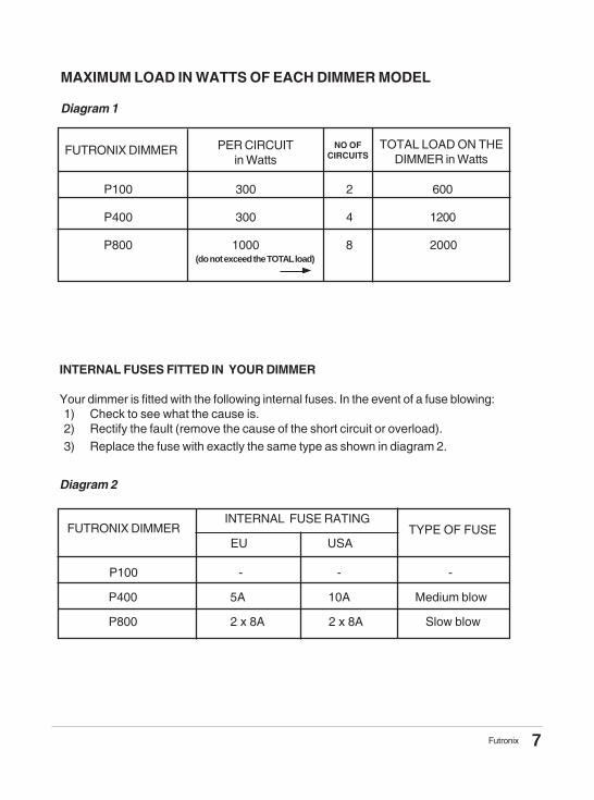
MAXIMUM LOAD IN WATTS OF EACH DIMMER MODEL
Diagram 1
FUTRONIX DIMMER TOTAL LOAD ON THEDIMMER in Watts
PER CIRCUITin Watts
P100 300 2 600
P400 300 4 1200
P800 1000 8 2000
INTERNAL FUSES FITTED IN YOUR DIMMER
Your dimmer is fitted with the following internal fuses. In the event of a fuse blowing:1) Check to see what the cause is.2) Rectify the fault (remove the cause of the short circuit or overload).3) Replace the fuse with exactly the same type as shown in diagram 2.
Diagram 2
FUTRONIX DIMMERINTERNAL FUSE RATING
P100 - - -
P400 5A 10A Medium blow
P800 2 x 8A 2 x 8A Slow blow
TYPE OF FUSE
(do not exceed the TOTAL load)
NO OFCIRCUITS
EU USA
7
Futronix
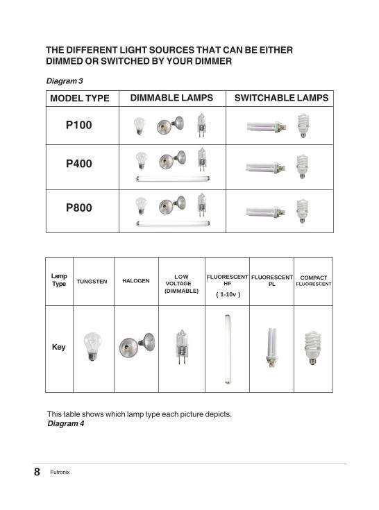
THE DIFFERENT LIGHT SOURCES THAT CAN BE EITHERDIMMED OR SWITCHED BY YOUR DIMMER
Diagram 3
MODEL TYPE DIMMABLE LAMPS SWITCHABLE LAMPS
P100
P400
P800
This table shows which lamp type each picture depicts.Diagram 4
LampType
Key
FLUORESCENTH F
TUNGSTEN HALOGENLOW
VOLTAGEFLUORESCENT
HF
( 1-10v )
FLUORESCENTPL
COMPACTFLUORESCENT
(DIMMABLE)
8

Futronix
* If you are using low voltage lamps (12v) then read this section as it is veryimportant.
TRANSFORMERS FOR LOW VOLTAGE LIGHTING - COMPATABILITY
Your Futronix dimmer is designed to dim on the LEADING EDGE of the mains AC powersupply sine wave. This is superior technology to LAGGING EDGE dimming used in someEuropean countries. If you are using transformers supplied from these countries or lightfittings with integral transformers, you will have to check to see that they can be dimmed byLEADING EDGE dimmers. This only applies to electronic transformers, Wire wound ones canbe dimmed by either type of dimmer. However, wire wound transformers are becoming lesspopular due to their larger size/ weight and lower efficiency.
If your electronic transformers are LAGGING EDGE, you will need to replace them with aquality LEADING EDGE electronic transformer. The UK/USA and most other countries in theworld use LEADING EDGE dimming as standard. Exceptions are European countries suchas Germany and Italy. If the transformer is of the wrong type it will not dim properly, it willgenerate more noise than usual and may damage the dimmer. If you don’t wish to changethe transformer you can always just set the circuit to “switching only”. The circuit can then beset up to either turn ON or OFF on any scene without dimming. (See the section describingthis on Page 29).
SELECTING THE LOCATION FOR MOUNTING YOUR DIMMER
The first thing when fitting a scene dimmer is to select the location where it is to bemounted. This is usually near to an entrance or where an existing light switch or manualdimmer is located.
The next thing to consider is the lighting in the room. Do you wish to upgrade it by fitting newlights or additional lighting? New lighting you might consider adding include wall lights, floor-mounted lights and low voltage lighting. All the lighting, new or old, should be wired back toyour new dimmer. The Lives enter the dimmer itself but the neutrals need to be commonedelsewhere. If you are unsure about this, then refer to the wiring diagrams in the sectionfurther on in the guide. If you have floor or table mounted lights, they should have their ownsocket; this is usually a 2A one or of a different type from the normal mains sockets used inyour country. This is simply to prevent accidentally plugging in another piece of electricalequipment. The number of circuits (also known as channels on the dimmer itself) should notbe greater than the number of channels on the dimmer.So, if you have a P400 dimmer, you should not have more than 4 circuits of lights, but youcould have less. There are no minimum loads on this range of Futronix dimmers. This meansunused channels can be left unconnected.
All the P100-400-800 range dimmers require a live and neutral supply (see diagram). If youare fitting your dimmer in an existing switch position, then there is very likely to be an existingLive supply. However, there may not be a Neutral supply. If this is the case, then one willneed to be fitted. This can be done at the same time as fitting any additional wiring for anynew circuits. All wiring should be done prior to fitting the mounting box and doing theplastering.
9

Futronix
* Wall box supplied with dimmer. All measurements in mm.
WALL BOX SIZES FOR EACH MODELDiagram 5
Question: Can I mount two dimmers near each other?Yes. During use, the switches on the front of each dimmer will operate just thatdimmer. The remote control will operate both dimmers, setting them to the samescene (subject to them being in proximity to each other). However, you will need toprogram them independently. To do so, give one of the dimmers a NEW uniqueprogramming “lock code” (see page 27). The dimmers can then be programmed oneat a time by entering the correct lock code for each one. Only the dimmer with thecorrect lock code will program.
FUTRONIX DIMMER Height Width Depth / Type
FITTING THE MOUNTING BOX
The P100 USA fits all existing standard American light switch wall boxes. In the caseof the P100 EU, an existing switch or dimmer wall box can be used if the box is 47mmdepth or greater. If you are using a new wall box, it should be a standard single gangsize of 47mm depth. These are available from most wholesalers and DIY stores.
The P400 and the P800 come with their own wall mounting box. The box should bemounted into the wall. A hole of the correct dimensions will need to be made in the wallto fit the box into it. The box needs to be secured to the back of the hole using masonryplugs and screws. The box then needs to be plastered around with filler to make it flushwith the final plastered surface of the wall.
P100 EU 75 75 (Metal)
P100 USA 77 50 60 (Metal/Plastic)
P400 * 88 108 50 (Plastic)
P800 * 102 160 70 (Metal)
10

Futronix
AN ELECTRICIAN’S TIPS ON HOW TO FIT A WALL BOX
Below a professional electrician gives his opinion on how to fit a new wall back boxwithout damaging the existing plaster or decoration.
The tools you will need are (a) Sharp razor bladed knife; (b) Sharp stone chisel 10mm orso wide; (c) Hammer - heavy for chisel; (d) Electric drill with bits; (e) Screws and wallplug pack.1) Put the new wall box in position up against the wall and hold it there. Use a spirit
level to make sure the box is straight.2) Use the sharp knife to cut round the box. This is done slowly, one side at a time.
The technique is to use many strokes starting at one end of each edge andmoving slowly along. Slow down near the end of each side to prevent over shootingthe box. Cut through the wallpaper and down to the depth of the plaster.NEVER HAVE ANY PART OF YOUR BODY IN FRONT OF THE CUTTINGEDGE OF A KNIFE - it could slip.
3) Once you hit the wall (brick or block wall) on all four sides, stop. Take away thebox and use the chisel to remove the plaster inside the cut out. Then start to chipaway at the wall inside the cut out, working from the centre out. Work slowly andchip a bit at a time to avoid cracking the wall. Carry on till you reach the correctdepth of the box and then chisel the corners out last. Carry on till the box will fitinto the hole.
4) Bring the wiring into the box and tape it out of the way. Drill the holes for the wallplugs. Fit them and screw the box into the wall. If the wall is not deep enough forwall plugs use quick setting cement behind & sides of the box to set it into.
Fit box flush with final surface
Diagram 6
Wall Box
Use screws and wallplugs to secure box to wall
Filler
Wall
Cut out section in thewall large enough to fitwall box
11

Futronix
A typical Wiring diagram for the P100 USA
Consumer unit
Diagram 7
12

Futronix
Wiring information.
All dimmers from this residential range require an EARTH connection*. Failure toensure an adequate EARTH connection renders the unit unsafe, invalidates thewarranty and is likely to mean the remote control will not function properly. It isthe responsibility of the person installing this dimmer to make sure that it isadequately EARTHED.
* The only exception is the P400 FUTURE which has a plastic front plate and does notrequire an earth connection.
Diagram 8
Consumer unit
13

Futronix
Consumer unit
Diagram 9
14

Futronix
A typical Wiring diagram for the P800
Diagram 10
Consumer unit
15

Futronix
Diagram 11
The Lives to the lighting circuits are connected to the terminals marked “1, 2, 3, 4, etc...”Neutral’s and Earth’s from each circuit should be commoned together (if not already).
P800Connect the supply and lighting connections to the terminal blocks pre-mounted in thewall box. Then firmly push the pre-wired terminal connector into the back of the dimmerunit, making sure it is fitted the correct way round.
DO NOT POWER UP BEFORE CONNECTING THE TERMINAL CONNECTORS
WARNING*All connections must be securely made before the power to the unit isturned ON. Similarly the power must always be turned OFF before any of theconnections are disconnected.
DO NOT PUT ANY SWITCHES on the channel outputs from the controller or onthe neutral side of the circuit.
Diagram 10 - above
All the dimmers require a Live and Neutral supply. These should be connected to theterminals marked L & N (L for LIVE and N for NEUTRAL). The supply from the powerboard should be MCB (miniature circuit breaker) protected or fuse protected. The protectionshould be rated at the maximum value of the dimmer rating. This is shown in Diagram 11below:Under the column “MCB or Fuse input protection”, the supply should be provided from theconsumer unit using a 1.5 mm2 cable, or a 2.5mm2 cable in the case of the P800.
FUTRONIX DIMMER
Maximum dimmerLOAD in Watts
Dimmerconnections to lighting
MCB or Fuse Protection
in consumer Unit
1, 2, 3, 4
L1,L26A
4A
6A
10 - 16A
600
600
1200
2000
P100 US
P100 EU
P400
P800
L1,L2
1, 2, 3, 45, 6, 7, 8
16

Futronix
Futronix recommend several makers of transformers which have been tested andapproved for use with Futronix dimmers. These are in addition to the range of Futronixtransformers which are of a high quality design and are guaranteed 100% compatablewith all Futronix dimmers. For information, contact Sales or see more details on ourWebsite: www.futronix.com
How to connect a transformer?
Common Neutral
Dimmer Live
12v.dimmed output
“ DIMMED ” OUTPUT FROM DIMMER
Low voltage12 v. lamp
etc..
L
L
N
NElectronic transformer
Futronix
Electronic transformerFutronix
Electronic transformerFutronix
17

Futronix
This range of sophisticated dimmers has many in-built features. In order to get the bestfrom your dimmer, please spend some time reading the next few pages before going onto program the unit.
What is scene setting?This is one of the most often asked questions. If you access webpage www.futronix.com/sceneset.htm, you will see a picture of the same room depicting different scenes. Sceneslike these can be set up by yourself and can be re-programmed at anytime. Eachcontroller has 20 Scenes, though in practice most customers are unlikely to use morethan 10. Each one of the 20 Scenes is a complete “look” to the room.
Once programmed, the different “Scenes” are selected using the switches on the frontof the controller or by remote control or timer.
When a new Scene is selected, it fades from the original set of Scene levels to the newset. This is called the ‘Fade rate’ and can be set from 0.5 sec to 2 hours.You can also think of it as the time taken for one scene to fade to become the next scene.This time is programmed from the remote control handset along with all otherfunctions. *
If you wish to override the fade rate and go straight to the new Scene, press the Up keyon the remote control after selecting the new scene. The Scene will change immediatelywith no fade.
When you wish to set up or alter a Scene, you must firstly enter program mode. Thenselect the scene to program, followed by the individual circuit to be adjusted. After that,use the raise/ lower keys to increase or decrease the level of brightness.
Then, select the next circuit on the same scene to be adjusted. Once all the circuits havebeen set up correctly on that scene they are automatically stored. *
P100, P400, P800 SCENE DIMMER
PROGRAMMING GUIDE
* see remote control layout page 22.* see flow chart diagram on page 24.
18

Futronix
The first thing to do once your dimmer has been installed is to set-up the DEFAULTFEATURES. It is important to set these up at this stage; if they are not set up correctlyyour dimmer may not function properly. Most of the features are for the P400 & P800,except for the power up defaults “C” and timer event zone “E” which apply to all models.
The following is a list of the parameters you need to set up.(for how to set up, see page 20)
Function P100 P400/ P800A The address of the
controllerSet the first controller to0, the next to 1, and soon. There are 16 possibleaddresses from 0-9, A-F
Set to 0 on this model
B Determines whichzone/s the controlleris operating
Set to F on this model The controller can operateany zone/s (see P800Zone table page 49)
C Selects the differentpower up options.
If 0 is selected: at power up, thecontroller will select scene 1If 1 is selected: at power up,the controller will select thelast scene in all zonesIf 2 is selected: at power up, thecontroller will select trailerIf 3 is selected: at power up, thecontroller will select houseIf 4 is selected: at power up, thecontroller will select Autorotate
Same as for P100
D Set to F on this model Autosequence can operateany zone/s (see P800Zone table page 49.)
Selects which zoneis controlled byAutosequence
E Timer Event zone:selects which zoneis affected bythe timer events
Set to F on this model The timer can operate anyzone/s (see P800 Zonetable page 49.)
F Occupancy Detectionsetup for P800
N/A Occupancy Detectioncan operate any zone/s(see P800 Zone tablepage 49.)
DEFAULT FEATURES
19

Futronix
How do I set up the DEFAULT FEATURES ?
If no keys are pressedfor 30 Sec then the unit
will EXIT programmode automatically.
Press and hold the sceneselect buttons on thefront of the dimmer for 5seconds until the display
shows A0 or A+some characters.
By pressing the ON key you can now select thedifferent defaults A to F.See the table for the list
of what the defaults are for.
The default setting letteris displayed on the left
while the setting value isdisplayed on the right.
Use the scroll scene keys tochange the default settings.
Once the default settingshave been correctly setup press OFF to exit.
or
20

Futronix
All the other dimmer parameters are programmed using the remote control handset.This is shown on the next page along with a description of the keys and their functionality.To be able to program any of the CUSTOMER SETTINGS, you will have to enter the lockcode first. This is factory set as 1 2 3 4 but you may change it at any time in the future.Should you forget it, there is a master lock code for your dimmer printed on page 57.
Press PROG then press 1 2 3 4 number keys one after the other slowly. The displayshould show P-, which is the base program mode. From here you can program all thefunctions including Scenes, Fade rates, Delay rates, Timer, Programming Code, TimedEvents, Clear Events, Copy One Day’s Events over to any other and Show what isprogrammed on Each Day.
When you are setting up a parameter, pressing Prog once at any point will let youescape back to P- mode. From here you can go on to program any other function.If you press Prog twice, then you will automatically come out of program mode.All parameters that you have programmed are automatically stored as you are settingthem up.
HOW DO I SET UP MY LIGHTING LEVELS?
The dimming on each channel can be set to any level (0-100%). This is displayed as0-63 levels. You first select the scene you wish to adjust before using the scroll keys toselect the circuit. Then, using the master raise/ lower keys, adjust the lighting to thelevel required. When you are happy with the level set and wish to store it, selectinganother circuit or scene will cause the settings to be stored automatically. There are 20such scenes available and each one is a complete “look” to the room.(See flow chart at page 24.)
While programming, the display tells you which scene you are adjusting and whichcircuit. In order to know which circuit number corresponds to which lights in the room,there is a test function. Simply press the Flash key and the lights on that circuit will startto flash on and off. When any other key is pressed it will return to the original programmedlevel.
As the Master analogue level resets itself to maximum during programming, all circuitlevel adjustments ought to be set for the maximum level likely to be required on eachscene.
Once you have made all the changes required, you can exit programming by pressingProg twice. The display will show En for End.
CUSTOMER SETTING
21

Futronix
The unit uses 4 AAA size batteries located under the cover on the rear of the unit.BATTERIES - MAKE SURE THEY ARE FITTED THE CORRECT WAY ROUND!(as per the diagram on the battery cover).
If the remote fails to function, they are possibly fitted the wrong way round. Do not leavethe batteries fitted incorrectly or damage to the unit will result.
Some of the keys on the handset have dual uses; for example, Key 10 in normal modebecomes 0 when programming in the time clock information.
THE INFRA-RED REMOTE CONTROL HANDSET
Raise / lower keysfor programming
light levels andmaster raise / lower
adjustment.
Number keys forselecting Scenes in
program / non programmode & for entering
timer information.
Auto sequencekeysProgramming keys
for setting up circuitparameter, fade / delay
rates & enteringprogram mode.
Circuit Scrollkeys for selectinga circuit duringprogramming.
OFF key
Timer keys forsetting up timerduring programmode.
ON key
22

Futronix
How do I enter the lock code?
Press Prog and the displayshould show P1.
Key in the lock code onedigit at a time.
The default code is1,2,3,4
Display will showP2,P3,P4
If code is correct, displaywill show P-
You can carry onto program the
If the code is incorrect, itwill show En for end.You
can retry entering the code.(If you experience difficulty
see page 27)
CUSTOMER SETTINGS
23

Futronix
If a circuit is set asswitching only(see page 29)
use the Up/Down keys toselect either 0 for OFF
or 1> for ON.
How do I program a scene?
Enter program lock code byPressing Prog then enternumbers 1 2 3 4 using the
number keys.
Display should show P-.If it doesn’t go to the“program lock code’’
flow chart on page 27.
Select the scene you wish toprogram by pressing oneof the number keys 1-20.
Select the circuit youwish to adjust on that
scene using the scroll keys.The circuit number will be
shown shimmering onthe display.
Use the raise/ lower key toincrease or decrease thebrightness of the circuit.
To select the next sceneyou wish to adjust, repeat.
To end programming, pressProg twice. Display shows
P- then En for end.
If you are not sure what lightsa circuit controls, you can
press the FLASH key.The circuit you have selectedwill then flash ON and OFF.
To select the next circuityou wish to adjust, on
the same scene, repeat.
24

Futronix
To copy another scenerepeat the process or
press Prog onceto go back to P-.
How do I copy one scene over to another?
You must be in programmode P- as above.
Select the scene youwish to copy
(the source Scene)by pressing one
of the number keys 1-20.
Press the buttonmarked Scene.
Press the scene number key that you wish to copy
the Scene to. Note: thememory of the targetscene will be wiped
and replaced bythe source scene.
25

Futronix
How do I select the fade rate I want?
To continue withprogramming pressProg once (display
shows P-) or press progtwice to end programming,
(display En for end.)
Enter program lockcode if not already in
program mode.Press Prog then enter
number 1 2 3 4.
Press FADE and thedisplay will show Fr.
Press a number keyfrom 1-20 dependingon the fade rate you
wish to select. (Refer tothe table opposite.)
Key No: Corresponding Fade Rate
123456789
1011121314151617181920
0.5 seconds2 Seconds4 Seconds6 Seconds8 Seconds
10 Seconds15 Seconds25 Seconds35 Seconds50 Seconds
1 Minute2 Minutes3 Minutes4 Minutes
10 Minutes20 Minutes40 Minutes
1 Hour1 Hour 30 Minutes
2 Hour
26

Futronix
How do I change the lock code?
Press the button labledCODE (display will
show SC for set code.)
The display will thencontinue to show the
code one digitat a time, until you press
Prog to go back toP- mode.
Enter your new code onedigit at a time.
The display will showC1, C2, C3, C4
as you are doing it.
Enter the program mode as described above. If youhave forgotten your lock code, refer to the masterone printed at the rear of
the book (P.57).
27

Futronix
Like DEFAULT FEATURES, these may need to be set up or your unit may notoperate correctly. The CIRCUIT PARAMETERS are to tell your controller informationabout what type of load is connected to an individual circuit. The P400/ P800 alsoneeds to know what zone a circuit is located in. Some loads, like compact fluorescents,need to be switched instead of dimmed. You can set this up and also tell the dimmer onwhat scenes you want the lamp to come ON and what scenes you want it to go OFF.
The P800 model can be used to operate up to 4 different rooms (known as zones).Any circuit can be assigned to be in any zone. The additional switch panel outstationsare then used to operate the lighting in each room.
CIRCUIT PARAMETERS
28

Futronix
How do I program a circuit to be switching only?
Enter program lock codeas described above.
Use the scroll keys toselect the required circuit.
The display will shimmerand will show thecircuit selected.
Pressing SWITCH willshow if the circuit has
been set as a dimmableone or a non dim one.
The display shows An foranalogue and oo
for switching.
Pressing SWITCH againwill toggle the circuit
between being analogueand switching only.
Refer back to how toprogram a Scene, to set acircuit, to switch ON and
OFF on a particular scene.
29
Futronix
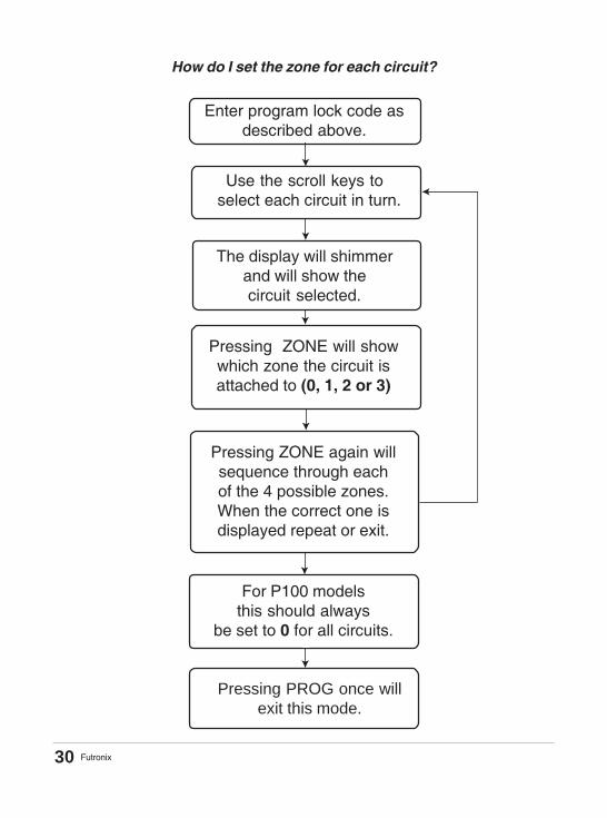
Enter program lock code asdescribed above.
Use the scroll keys to select each circuit in turn.
The display will shimmerand will show thecircuit selected.
Pressing ZONE will showwhich zone the circuit isattached to (0, 1, 2 or 3)
Pressing ZONE again willsequence through eachof the 4 possible zones.When the correct one isdisplayed repeat or exit.
For P100 modelsthis should always
be set to 0 for all circuits.
How do I set the zone for each circuit?
Pressing PROG once willexit this mode.
30

Futronix
How to set the Timer?
The P100-P800 models of dimmer come fitted with a built-in timer. The timer operates ona 24 hour 7 days per week basis. The timer can be programmed to select any scene(including ON or OFF) at anytime of the day or week - these selections are calledEVENTS.
You will have to enter the following information for the timer to function:a) The time and the day of the weekb) Each Event (that you wish the timer to select) and the time at which you want it to
occur.
How do I program the timing functions?The clock time and day are entered by pressing TIME then keying in the time in 24 hourformat. For example, 10.35 am. is entered as 1, then 0, then 3, then 5.The day is entered by pressing a number corresponding to the day as follows:1=Mon, 2=Tues, 3=Wed, 4=Thur, 5=Fri, 6=Sat, 7=SunThe number can only be 1 to 7.
Example:So 1.25pm on Wednesday would be 13.25 entered as 1 then 3 then 2 then 5 followed by3 for the day (Wednesday). When entering a zero use the number key 10, which doublesas 0 in this mode.
The time is then shown as the hours first followed by minutes. The day is shown on thedisplay as (d+ number) relating to the day. (See the flow diagram on the next page forhow to set the time.)
31
Futronix
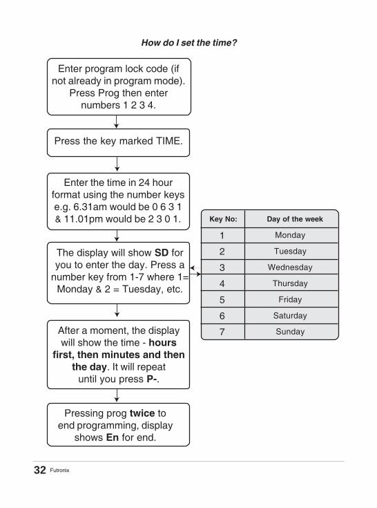
How do I set the time?
Enter program lock code (ifnot already in program mode).
Press Prog then enternumbers 1 2 3 4.
Press the key marked TIME.
Enter the time in 24 hourformat using the number keyse.g. 6.31am would be 0 6 3 1& 11.01pm would be 2 3 0 1.
After a moment, the displaywill show the time - hours
first, then minutes and thenthe day. It will repeat
until you press P-.
The display will show SD foryou to enter the day. Press a
number key from 1-7 where 1=Monday & 2 = Tuesday, etc.
Key No: Day of the week
1
2
3
4
5
6
7
Monday
Tuesday
Wednesday
Thursday
Friday
Saturday
Sunday
Pressing prog twice toend programming, display
shows En for end.
32
Futronix
You can program the dimmer to automatically select up to 10 different Scenes or EVENTSto occur each day. Each event switches the controller to a Scene 1-20, ON, OFF, or oneof the 3 Autosequencing modes. When we program these Events we do so for each dayof the week in turn.
The sequence of programming is as follows:1) Tell the controller which day you want to program the Events on:where 1=Mon, 2=Tues, 3=Wed, 4=Thur, 5=Fri, 6=Sat, 7=Sun.2) Tell the controller which Event number (1-10) on that day you wish to program.The Events can be entered in any order (for example, Event 2 can occur before Event1) though generally it is best to enter the EVENTS in the order that they occur forsimplicity.3) Enter the function (Scene 1-20, ON, OFF or Autosequence) you want it to switch to.4) Input the time at which you want it to implement the change.
We only need to program in a start time because the Event will continue until the nextone is selected. Whenever the timer selects an Event it can always be overridden byselecting another from the front panel or remote control. The timer would then continueand select the next Event whenever it occurs. If you want to turn the lights OFF just setan EVENT to select OFF at a particular time.
For example, Scene 1 could be selected by the timer at 12.00, then Scene 2 at 15.30,then Scene 3 selected manually, then OFF selected at 23.05 by the timer. The lights willswitch from Scene 1 to 2 to 3 manually then OFF.
It is best to program in the main Events and leave the variable ones to be selected by theend users, though you may wish the timer to select a scene even if it is not alwayssuitable. The user can then select another if required i.e. the timed function is just asuggestion.An example of this could be selecting a security scene at night if the building is unoccupied.If it is occupied the user can just select another scene.
If you wish to program the same Events to occur on more than one day, then one day’ssettings can be easily copied to any other day. Similarly, Events can be cleared individuallyor for a whole day. To see what you have programmed, you can press SHOW, which willshow you what is programmed for all 10 Events on that day.
If you wish to temporarily cancel the timer functions just press CANCEL from the normalmode (you don’t need to be in program mode). This then cancels all timer functions forthe next 12 hours. The display shows TC for Timer Cancel.
Programming the unit to bring on the correct scene at the requiredtime.
33

Futronix
How do I program a scene to come on at a particular time?
After a moment thedisplay will show the
EVENT followed by thetime - hours first thenminutes. To program
another EVENT repeat.To program on anotherday repeat from here.
Enter program lock codeas described above.
Press the P-DAY key(display shows Pd) thenpress a number key 1-7
corresponding to the day.
Press EVENT (displayshows PE) followed by the
Event number 1-10.
The display will show anyEvents that are alreadyprogrammed. If none are
programmed then the displaywill show -- followed by00 hours & 00 minutes.
Press the key of the function that you
wish to occur. This can beScene1-20, ON, OFF or
Autosequence mode.
Now enter the time that you want theEVENT to take place in 24 hour format.Use the number keys e.g. 6.31am wouldbe 0 6 3 1 & 11.01pm would be 2 3 0 1.
34
Futronix
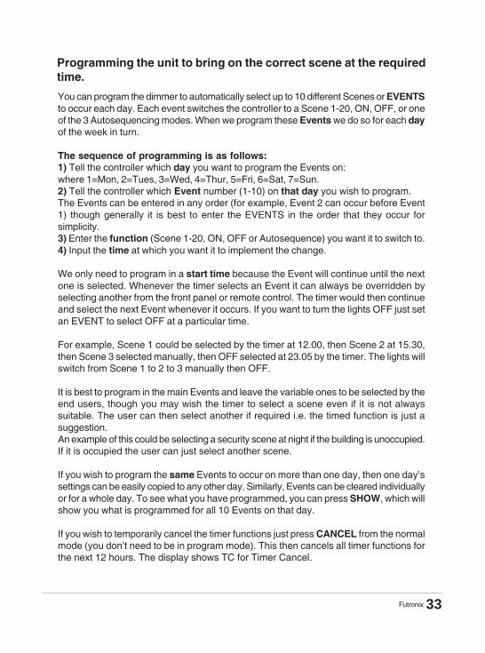
How do I copy one day’s EVENTS to another day?
Enter program lock codeas described above.
Press the P-DAY key(display shows Pd) then
the number of the dayyou wish to copy from.
Press P-DAY again (displayshows Cd for copy to day).
Then press number keyfor the day you wish
to copy to. i.e. the target.
To copy the eventsto another day, repeat.
35

Futronix
How do I clear EVENTS?
Enter program lock code asdescribed above (if notalready in Prog mode).
Press the P-DAY key(display shows Pd) then thenumber of the day you wish
to clear the Events from.
Press EVENT (display shows PE) and then key in the
number of the Event 1-10you wish to clear.
Then press CLEAR to clearthat event.
The display then shows --followed by 00 hours and00 minutes as nothing is
now programmed. Repeat to clear the next Event.
Continue by going back toentering timer Events or pressProg to go back to P- mode.
36
Futronix
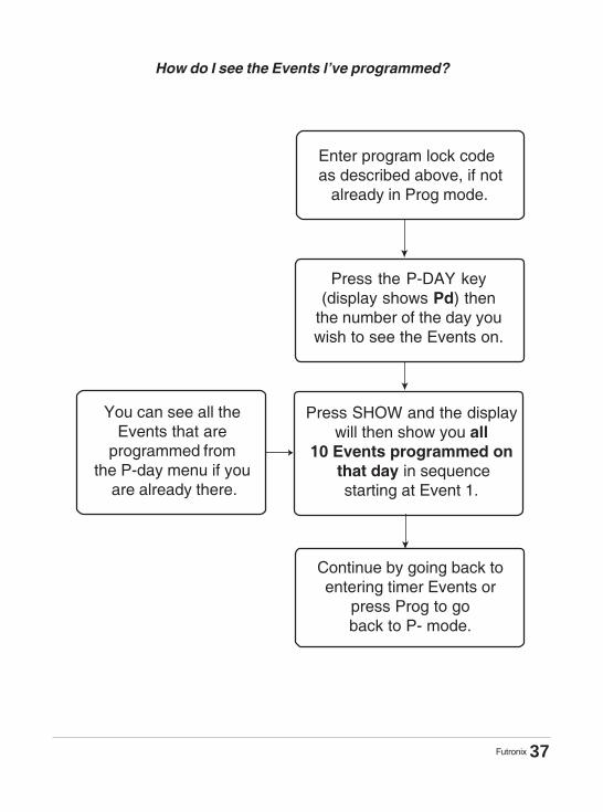
How do I see the Events l’ve programmed?
You can see all theEvents that are
programmed fromthe P-day menu if you
are already there.
Press the P-DAY key(display shows Pd) then
the number of the day youwish to see the Events on.
Press SHOW and the displaywill then show you all
10 Events programmed on that day in sequence
starting at Event 1.
Continue by going back toentering timer Events or
press Prog to goback to P- mode.
Enter program lock codeas described above, if not already in Prog mode.
37

Futronix
SLEEP TIMER/ EXIT DELAY
This feature is used when you want to turn the lights OFF after a period of time.
For example, when the dimmer is fitted in a bedroom, the delay function can be usedto turn the lights OFF for you after you have gone to sleep. The timer delay only workswhen switching from Scene 1 to OFF. It doesn’t work when switching from Scene 1 toother scenes or from other scenes to OFF. This is so that the delay can be left set bythe user and not interfere with normal use.
This function can also be used as an exit delay where illumination is required to exitafter turning the lights to OFF. Usually this is where the dimmer or switch panel is notmounted near the exit, or there is more than one exit. The delay can be set from a fewseconds to 2 hours in duration.
38

Futronix
How do I set the Sleep timer delay?
Enter program lock code (ifnot already in programing
mode). Press Prog then enternumbers 1 2 3 4.
Press SLEEP button and thedisplay will show Ed.
Press a number key from1-20 for the required
delay rate. If nodelay is required select 1.
Display shows the valueselected.
To continue withprogramming press Progonce, (display shows P-)or press prog twice to end
programming, (displayshows En for end).
Key No: Corresponding Delay time
123456789
1011121314151617181920
no delay2 Seconds4 Seconds6 Seconds8 Seconds
10 Seconds15 Seconds25 Seconds35 Seconds50 Seconds
1 Minute2 Minutes3 Minutes4 Minutes
10 Minutes20 Minutes40 Minutes
1 Hour1 Hour 30 Minutes
2 Hour
39

Futronix
AUTOSEQUENCE and DISPLAY
The P100, P400 and P800 models have 3 sequencing modes. They are AUT, Houseand Trailer.
AUT (Autosequence) is used for exhibitions and displays where there is a requirementto cycle through the Scenes sequentially. There are 2 adjustable parameters; one isthe HOLD time, which determines how long a scene is held for before going on to thenext. The other is the FADE rate, which determines the rate that the old scene fadesinto the new one. AUT selects each scene in turn from 1-20 and then starts back atscene 1 again. If less than 20 scenes are required, the unused ones can be leftunprogrammed (i.e. all channels set to 0) and these scenes will then be skipped.
HOUSE. When this key is pressed, the controller will sequence through Scenes 6 - 10and then stop. This feature is very useful for sequencing a presentation where thescenes can be set up to provide a small light show. A single press of the key theninitiates the sequence. If a shorter sequence is required, then leave unprogrammedthe scenes you wish to omit. For example, you could omit scenes 6 and 7 (all channelsset to 0). These scenes will then be automatically skipped.
TRAILER sequences through each scene in turn from 10-14. If less scenes arerequired, the unused ones can be left unprogrammed (i.e. all channels set to 0) andthese scenes will be skipped.
FEATURE sequences through each scene in turn from 14 –16. Again, if fewer scenesare required, the unused ones can be left unprogrammed (i.e. all channels set to 0)These scenes will then be missed out.
The HOLD speed can be set from 0 sec - 2 hours. When cycling through there is theproviso that each Scene completes its Fade In before going on to the next. This is toprevent the situation where there is a short hold (cycling speed) but a long fade ratewhich leads to continuous level changing.
40

Futronix
How do I set the Hold time for the scene in Autosequence mode?
Enter program lock code (ifnot already in programing
mode.) Press Prog then enternumbers 1 2 3 4.
Press Hold button(the display will show Hd).
Press a number key from1-20 for the required
Scene Hold time. If nohold is required, select 1.
Display shows thevalue selected.
To continue with programmingpress Prog once, (displayshows P-) or press prog
twice to end programming(display En for end).
Key No: Corresponding HOLD time
123456789
1011121314151617181920
no delay2 Seconds4 Seconds6 Seconds8 Seconds
10 Seconds15 Seconds25 Seconds35 Seconds50 Seconds
1 Minute2 Minutes3 Minutes4 Minutes
10 Minutes20 Minutes40 Minutes
1 Hour1 Hour 30 Minutes
2 Hour
41

Futronix
CHANGING LIGHT LEVELS WITHOUT STORING THEMPERMANENTLY
This function allows the user to alter the level of any circuit without storing it permanently.Each circuit can be adjusted from 0-100% regardless of what it was before.
Select the Scene you wish to temporarily modify using a scene key 1-20. Then, using thescroll keys, select the circuit to be adjusted. The display will shimmer and show thecircuit you wish to adjust. Use the raise/ lower keys to increase or decrease the level ofbrightness of that circuit. To adjust another circuit, use the scroll keys again to selectanother circuit. Then use the raise/ lower keys to adjust it to the new level. You can goback and adjust another circuit if you wish. Once you have finished all the alterationspress Prog twice to go back to normal mode.
MASTER RAISE/ LOWERThis varies the output levels of all the circuits up and down keeping the ratios intact,working across all scenes. Master RAISE / LOWER changes are inhibited when thecontroller is switched to OFF. It also resets to maximum level at initial power up andwhen ON or programming mode is entered. It works on the output of the circuits thatare set into the same zone as the dimmer or switch panel is operating in.
THE P400/ P800 ACCESSORIES
Home-Icon Color Touch-Screen
P800
The rear connector on your P400 or P800 is fitted with a direct IR input which can beconnected to the Futronix Home-Icon color touchscreen. This facility means that yourdimmer can be operated as part of a whole housenetwork by inter-connecting to other Futronixdimmer systems. Alternatively third partyequipment, with an IR output, can control thedimmer if installed with the correct Futronix codes.
A low voltage cable (not CAT5) should be used toconnect the two-wire connections which areCOMMON & IR to the touch screen.
42

Futronix
The P400 & P800 are flexible and can be expanded to control the lighting in up to fourdifferent rooms. These rooms or areas are called ZONES. Each P800 can control 8circuits of lighting; where there are more circuits, additional P800s can be connected.The maximum number of P800s that can be connected together is 8, giving a total of 64channels. An example of this would be if you were using the system to control a completehouse. Each P400 can control 4 circuits of lighting.
To control the system from more than one point, switch panel outstations can be added.The switch panels are from the PFX/ Enviroscene range and are available in a widevariety of finishes. The switch panels and dimmers are inter-connected using the same4-core cable. The dimmers or switch panels can beconnected at any point on the databus. It is goodpractice to have a controller at the start of the busand a switch panel at the final end. The switch panelpower is derived from the dimmers and each onecan power 3 switch panels. The Maximum numberof switch panels that can be used is 3 per dimmer.
Note:L1 & L2 outputs on the P400 are controlled bychannels 5 & 6 when being programmed or operated.
ZONING & SWITCH PANELS
SPECIAL FEATURES
LED/ Fluorescent dimmingThe P800 is fitted with 4 channels of 1-10v LED/ Fluorescent ballast control, and theP400 with two channels. This is compatible with all makes of ballast that are fitted witha 1-10v input. Connect all the ballast 0v commons to the terminal marked 0v. Connecteach of the ballast circuit (+) to the terminals marked output 1-10v. As many as 30ballasts can be driven from each of the outputs. The terminals on P800 are high qualityspring loaded design - insert a screwdriver into the slot above the terminal and lever thescrewdriver upwards until the terminal opens, insert the wire and remove the screwdriver.
The minimum dimming level is determined by the ballast manufacturer. In order toextinguish the ballast completely it is necessary to use one or more channels of dimmingto provide the mains power supply to the ballasts. The channel/s need to be set asswitching only (see page 29).
MAKE SURE THAT THE TOTAL LOAD DOES NOT EXCEED THE MAXIMUM SETFOR EACH CHANNEL OF DIMMING OR FOR THE WHOLE DIMMER.
P400
43

Futronix P800 & ELECTRONIC BALLAST CONNECTIONS
[ Using circuit 5 as an example ]
44

Futronix
The databus address is a number from 0-31 that must be programmed for each dimmeror Switch Panel connected on the same databus. The master dimmer (the first one)should have an address of 0. Any other dimmer should have an address set from 1. Theswitch panel addresses should be numbers higher than any dimmer. All addresses mustbe UNIQUE. No dimmer or switch panel should have the same address as any other.
For example a system of 3 inter-connected P800s and 4 switch panels could have theaddresses as shown below.
DATABUS ADDRESS
EQUIPMENT ADDRESS (UNIQUE)
P800 -1 (Master) 0
P800 -2 1
P800 -3 2
Switch panel 1 3
Switch panel 2 4
Switch panel 3 5
Switch panel 4 6
How do I set the P400/ P800 address?
You will need to refer to the Page 20 section marked DEFAULT FEATURES.Below is a copy of the table from that page.
-
DEFAULT FEATURES (Copy from before)
The address of the P800 controller
Function P100 P400/ P800
A ------------------ Set the first controller to 0, the nextto 1, and so on. There are 16possible addresses from 0-9, A-F
45
Futronix
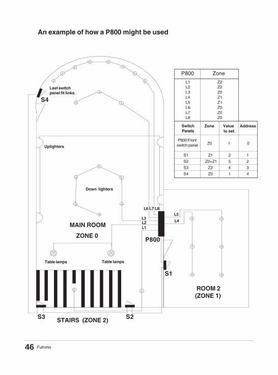
An example of how a P800 might be used
S4
S3 S2
S1
P800
L1L2L3
L4
L5L6 L7 L8
STAIRS (ZONE 2)
MAIN ROOM
Down lighters
ROOM 2 (ZONE 1)
Last switchpanel fit links.
Uplighters
Table lamps Table lamps
P800 Zone
L1 Z2 L2 Z0 L3 Z0 L4 Z1 L5 Z1 L6 Z0 L7 Z0 L8 Z0
Zone Value Address to set
P800 Frontswitch panel Z0 1 0
SwitchPanels
ZONE 0
S1 Z1 2 1
S2 Z0+Z1 5 2
S3 Z2 4 3
S4 Z0 1 4
46

Futronix
ZONEThe system is very flexible and allows any of its circuits to be assigned in any zone (notnecessarily the same room as the dimmer itself). For example, circuits L 1,2,3,4,5 couldbe set up to be in the first room (zone 1). As there are 3 spare circuits, they could be setto control a second room (zone 2). Additionally, the front switches on the controller canbe set to control any zone or zones as can the switch panels.
* Copy of table from page 19.
ZONE/ S CONTROLLED BY THE FRONT PANELHere we are simply referring to what zone or zones are controlled by the switches on thefront of a dimmer and by it’s Infra-red receiver, NOT what zone any of it’s circuits areworking in. Set the value according to page 49 by following the instructions below.
THE 3 ZONING PARAMETERS THAT NEED TO BEPROGRAMMED
1 Which zone number each of the circuits the dimmer is operating in. Any of thecircuits could be operating in any of the 4 possible zones (0-3).See the section “setting the Zone for each circuit” on page 30.
2 The zone/ s controlled by the front panel of any dimmer. (See below.)
3 The zone or zones that a switch panel is controlling. It could be the room/ zonethat it is located in, or it could be other zones as well. (See page 49.)
DEFAULT FEATURES
Letter displayed &corresponding
Function
The controller can operate any zone/s(see P400/ P800 Zone table page 49.)
The address of thecontroller
Set the first controller to 0, the next to 1 and soon. There are 16 possible addresses from 0-9,A-F
Determines whichzone/s the controlleris operating
P400/ P800
A
B
47
Futronix
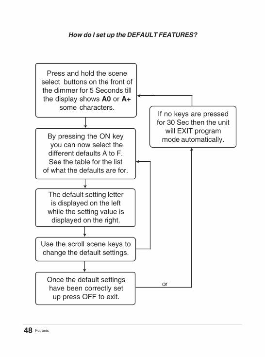
How do I set up the DEFAULT FEATURES?
If no keys are pressedfor 30 Sec then the unit
will EXIT programmode automatically.
Press and hold the sceneselect buttons on the front ofthe dimmer for 5 Seconds tillthe display shows A0 or A+
some characters.
By pressing the ON key you can now select thedifferent defaults A to F.See the table for the list
of what the defaults are for.
The default setting letteris displayed on the left
while the setting value isdisplayed on the right.
Use the scroll scene keys tochange the default settings.
Once the default settingshave been correctly setup press OFF to exit.
or
48

Futronix
Displayed Value
0 None1 02 13 0 + 14 25 0 + 26 1 + 27 0 + 1 + 28 39 0 + 3A 1 + 3B 0 + 1 + 3C 2 + 3D 0 + 2 + 3E 1 + 2 + 3F 0 + 1 + 2 + 3
Circuit Zone/s that will becontrolled
P400/ P800 ZONE TABLE
Note:In use the displays of both the P800 and the switch panels will show the last scenechange of the lowest zone number set.
Example: P800 ZONE TABLEIf displayed value was set to 5, the display will show scene changes in zone 0. If thedisplayed value was set to 6 it would show the scene changes in zone 1 etc.
49

Futronix
SWITCH PANEL OUTSTATIONS (P800 MODEL ONLY)
The keys on the switch panelshave the same function as onthe main controller.
The ON key turns the lightson to 75% with an almostinstant 0.5sec fade.
The OFF key turns the lightsoff at the same fade as youset for the rest of the Scenes.
The Scene scroll up keyscrolls through the scenenumbers from 1-20.
The Scene scroll down keyscrolls through the scenenumbers down to 1.
This window is a combined display andInfra-red receiver. The display in normal modeshows the scene selected. In program mode itshows the relevant programming information.
50

Futronix
FITTING SWITCH PANEL OUTSTATIONS (P400 / P800 models ) only
The switch panels are the same as for the commercial ranges and are available in avariety of finishes. You will need a back wall box of at least 35mm depth. This needs tobe pre-mounted with the control cable run to the dimmer. If there are several switches orseveral dimmers then the cable needs to be daisy chained from one to the next.
The control cable should be 4 or 6 core screened 7/0.2mm2 core. (Telephone, CAT5 oralarm cable is NOT acceptable). Futronix can supply control cable in 100m. drums.
Connect the cables in accordance with the diagram above. The cores are labelled asfollows: [0v, CLK, DATA, 12v]. There can be several switch panels connected to eachcontroller system and cable distances can be up to 150m between switch panels andcontrollers. The switch panels should be daisy chained together one to the next etc.
The 4 connectionsare labelled+12v,Data,CLK,0v.
The switch panels require a 4core screened cable, and areconnected in a daisy chain fromone panel to the next.
Switch Panels
51

Futronix
On the last switch panel the two links will need to be fitted.Remove links from all other panels.
Note : on SP4 switch panels there is a 3 rd link which, if removed, disables theInfra-red receiver.
FITTING LINKS TO LAST SWITCH PANEL
P800 dimmer inter-connections
Inter-Connecting P400/ P800s
The switch panels require a 4core screened cable, and areconnected in a daisy chain fromone panel to the next.
The 4 connectionsare labelled+12,Data,CLK,0v
back back back
P800 dimmer P800 dimmer P800 dimmer
Fit LINKS to last panel indaisy chain.
Remove LINKS from allother panels.
INFRA - RED RECEIVER DISABLE
Etc... To next dimmer or switch panel
52

Futronix
PROGRAMMING THE SWITCH PANELS
The Switch panels need to be programmed with a Databus Address and Zone information.
ADDRESSTo put the switch panel into program mode press both the Scene scroll up and downkeys simultaneously, holding them in for 5 seconds until the display changes to Pr. Usethe ON key to toggle through the different programming functions. The address isindicated by letters Ad and, when ON is pressed again, the value is displayed. Tochange the address, use the scene scroll up and down keys till the correct value isshown. The address for each switch panel must be UNIQUE and of a higher value thanthat of any P800 connected on the same databus.
For exampleA dimming system comprising of one P800 and three switch panels:The P800 address would be 0, and the switch panel addresses could be 1, 2 & 3.
A dimming system comprising of three P800 and four switch panels.the P800s addresses would be 0, 1, 2 and the switch panel addresses could be 3, 4,5, 6.
ZONEEnter program mode (as described above under ADDRESS) and press ON again untilthe display shows 3 horizontal bars on the left digit with the zone value indicated on theright digit. To change the value use the scene scroll up and down keys. Refer to theP800 ZONE TABLE on page 49 to select the VALUE corresponding to the zone/s youwish to control.
When the switch panel has been set up, pressing OFF will exit programming mode. Enis shown on the display for end of programming.
53
Futronix
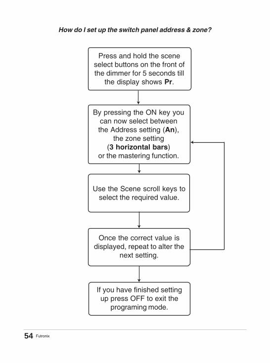
How do I set up the switch panel address & zone?
Press and hold the sceneselect buttons on the front ofthe dimmer for 5 seconds till
the display shows Pr.
By pressing the ON key youcan now select betweenthe Address setting (An),
the zone setting(3 horizontal bars)
or the mastering function.
Use the Scene scroll keys toselect the required value.
Once the correct value isdisplayed, repeat to alter the
next setting.
If you have finished settingup press OFF to exit the
programing mode.
54

Futronix
ZONE/SCircuit is
operating inLighting Circuit description
Table showing what lights are controlled by each circuit (please fill in anduse when you come to program - so you know which circuits are which)
CircuitNumber
1
2
3
4
5
6
7
8
9
10
11
12
13
14
15
16
55

Futronix
FAULT FINDINGTypical customer questions and answers:
1) A circuit of lights is permanently ON and will not go off when OFF is pressedIf all the circuits aren’t functioning check to see that the front display is lit. If not thencheck the power supply to the dimmer. Check the fuses (P400 and P800 only). If a fusehas blown then a short circuit or overload may have occurred. If that is the case find thecause and rectify. Replace the fuse with the correct type as shown in the table onpage 7.If the fuse has not blown then check the circuit parameter settings under the sectionCIRCUIT PARAMETERS on page 28. The circuit may have been set into another zone.
2) A circuit of lights is permanently ON and will not go off when OFF is pressedCheck to make sure that the circuit parameters are correctly set under the sectionCIRCUIT PARAMETERS on page 28. The circuit may have been set into another zone.Did a short circuit occur, or a lamp blow before the problem occurred? Although highpower devices are used, it is possible that a Triac (output device) has been damaged.Short circuits can create large current and voltage peaks for short periods of time.If this is the case you will have to return the unit to your nearest Futronix repair center.
3) Remote control will not workIf the remote control doesn’t function check the following:a) Battery flat or missing in the handset.b) Battery installed wrong way round.c) The dimmer is not EARTHED properly. If the dimmer has a metal finish it MUST
BE EARTHED properly.d) Light from light fittings (particularly high frequency fluorescent) or sunlight entering
the receiver window.e) Electrical noise from dimmed source affecting the unit. Try swapping circuits around.
If low voltage transformers are used check to see none are faulty throughsubstitution. Swap transformers to a higher quality brand.
f) Some TV’s (plasma) or other equipment can emit strong IR (INFRA-RED) noise.Try switching off other equipment in the room and see if you can identify theproblem source.
g) The remote control is being used too close to the switch panel - try to aim it inanother direction from the wall panel or stand back from the panel.
56

Futronix
4) You cannot enter program mode after 1 2 3 4 has been keyed inAn unknown lock code may have been entered or the non volatile memory may becorrupted. Enter the master program lock code 2 4 7 3 instead. Re-enter lock code(see page 27).
5) The dimmer makes a buzzing noise and the lights aren’t dimming properlyAre you using low voltage lights and if so have you checked to see that they areLEADING EDGE transformers and not LAGGING EDGE transformers? Refer to thesection on page 9 called: TRANSFORMERS FOR LOW VOLTAGE LIGHTING –COMPATABILITY
6) The dimmer is making a buzzing noise, but the lights are dimming OKThe first thing to say is that all dimmers by their nature will make some noise. Futronixdimmers being all digital are quieter than most dimmers. Excessive noise can be generatedby having the wrong transformers fitted as decribed above.Noise can be generated by the transformers and the fittings themselves. We wouldrecommend you swap transformers for high quality ones (Futronix) and/ or change yourfittings for higher quality ones. The mounting of both of these items can influence noise.Transformers should be mounted where vibration from them cannot be amplified. Anexample of this is where they are left lying on a plaster board ceiling void.
7) The dimmer appears to overheat (the front plate is quite hot)Check the loadings. Add up the number of lamps and the wattage of each one. The totalon each circuit should be less than the MAX value of your dimmer (See Diagram 1 page7.) The total load of all circuits shouldn’t exceed the TOTAL given for the dimmer (takeinto account the load of a low voltage transformer, i.e. a 50Watt 12v lamp will have ahigher loading due to the transformer losses). Transformers often go faulty (wire woundand electronic) and can then consume a lot more power than their rating. It is worthchecking all the low voltage transformers. A bad one will often get quite hot. If you are notsure, substitute with a known good transformer.
The rule of thumb is: if the dimmer is getting hot it is unlikely to be the dimmer,almost certainly it will be a problem with the LOAD connected to it.
8) There was a power out and now the dimmer won’t work properlyIf there was the chance of a power out (you may not know if one occurred), then it ispossible that, when the power resumed, there would be a large surge. This can lead tothe dimmer not resetting correctly. Simply power OFF the mains supply to the dimmer.Wait 20 Seconds, then power it quickly (cleanly) back on. Your dimmer should now befunctioning correctly again. If you power it on and the mains contacts are allowed to arc,then the dimmer won’t reset properly.
57

Futronix
9) Scene 1 is the only scene that can be selected. After selecting another scene thedimmer jumps back to Scene 1 againHave you set up the DEFAULT FEATURES? Go to page19 and follow the set uproutine. If you have already done so, then check them through to make sure that theyare set to the correct values. Once you set these up correctly for your model of dimmerthen the problem should have been corrected. If you have a P800, check to see that thelinks are fitted on the last panel ONLY. (See page 52.) Check to see that the switchpanels are correctly connected and programmed.
10) The timer won’t bring on the correct scene at the programmed timeCheck to see that the timer is at the correct time and is working. Then check to see thatthe Events are set up for the time you want. You can use SHOW to show the Events thatare programmed on any particular day. See (page 37.)
Check the DEFAULT FEATURE relating to the timer as it might not be set up correctly.The function is Timer Event (E). For the P100 this should always be set to F. For theP400 & P800 it should be set to the zone that it is controlling.
Have you pressed the CANCEL key on the remote control out of program mode? If sothis cancels all the timer events for the next 12 hours. If you turn the power to the dimmerOFF and back on again this will clear.
11) Lights flicker or pulse when turning OFF - P400This can occur if there is a non-inductive load on circuit 3 or 4. Try swapping the circuits3 and/ or 4 around with circuits 2 and/ or 1.
12) Autosequence cycles quicklyThis is because there are no times programmed in the memory. Go to Prog mode andset Fade to equal say 2 and HOLD to equal 2. Come out of prog mode and try AUT again.
13) The lights won’t dim when OFF is selectedOccurs when changing from scene 1 to OFF. It is likely that a delay has been set via theSLEEP function. See programming the SLEEP timer on Page 39.
58

Futronix
GLOSSARY OF TERMS :
Autosequence........... A set of scenes that are selected in sequence with a programmabletime duration between them. Useful for light show or display use.
Cancel....................... Cancels all timer selections for the next 12 hoursChannel..................... Output circuit on dimmerCircuit....................... One or more lamps wired to operate together and powered via a
switch or dimmer.Circuit Parameters... A programming feature which tells the dimmer information such
as: is a circuit dimming or switching only and what zone is it in.Customer Settings.... The lighting levels and timer settings etc.. that you wish to set up.
These settings can be altered whenever you want and are storedpermanently, even when the power is turned off.
Databus.................... A databus is a communication exchange between two or moredevices. In the case of the P800 this is between the switch panelsand one or more P800s via a wire link.
Databus Address..... Each device connected to the databus has to have a unique addressset up at programing time.
Default Features...... A programming feature which tells the dimmer information such aszoning information, which scene is selected at power up, whichzone is selected by the timer etc.. Needs to be checked/ setup atprogramming time. A scene or sequence that can be selected tooccur at a particular time.
Event........................ A scene or sequence that can be selected to occur at a particulartime.
Exit Delay................. Provides a delay where the lights will remain on for a period of timeafter they have been turned OFF to permit exiting from a room.
Fade Rate................ The rate at which one scene fades into another scene. Typicalfade rates are 4-10 seconds. The value set applies to all scenefades.
Flash....................... Turns the selected circuit ON and OFF alternatively so you canidentify it while programming.
Frequency............... The frequency of the mains system in your country. Futronixdimmers are available in 50Hz & 60 Hz versions; 60Hz is used inUSA, Canada/ the American continent, Saudi Arabia, Taiwan,
Korea, Philipines & part of Japan; 50Hz is used in the rest of the worldincluding Europe, China, SE Asia, Middle East & Africa.
Fluorescent ............. This type of lamp can only be switched ON or OFF. If a dimmable1-10v ballast is installed in each light fitting the Enviroscene &P800 P400 1-10v output can dim them.
Halogen.................... Tungsten halogen lamps come in mains voltage and low voltageversions. They offer a crisp white light at full brightness and dimthrough shades of yellow and orange. They give a better light thantungsten and are more efficient.
59

Futronix
Hold................................. The length of time that a scene is held before the next sceneis selected in Autosequence mode.
Lock code....................... Program access code which can be altered to preventunauthorised tampering.
Low voltage transformer..See: TransformerRaise/lower...................... Raise/ lower keys on the remote control let the user adjust
individual circuit levels in and out of program mode as well asadjusting the master raise/ lower.
Remote control................ Used for selecting scenes and programming the dimmer.Your dimmer is supplied with a full function remote (RC50)A smaller reduced function one is also available (RC20).
Scroll Keys.......................Scroll keys on the remote control let the user select anycircuit for programming starting at 1.
Sleep timer....................... Provides a delay where the lights will remain on for a period oftime after they have been turned off.
Switch panel.....................Wall mounted switch which can be connected to the P400/P800 to act as a wall mounted outstation or remote controlpoint.
Transformer.................... Necessary for controlling low voltage lighting. Steps mainslevel voltage 230v(Europe) or 120v type voltage (USA) downto 12v.
Tungsten........................ Standard light bulbs usually available in bayonet and screwfitting. Inexpensive to purchase and can be directly dimmedby any dimmer.
Timer............................... Built in timer that can be programmed to select any scene atanytime of the day.
Volts................................. The voltage of the mains system in your country (220-230vsingle phase or 120v single phase/208v twin phases).
Watts................................Measurement of electrical power consumption. If four 60Wlamps are connected to a dimmer then they will have a powerconsumption rating of 240w. The power rating can also bederived from multiplying the current in Amps by the mainsvoltage. P = A x V correctly known as P = I V
Wall Box.......................... The back box used for mounting the dimmer to the wall.Normally the box is mounted flush into the wall. The dimmerscan also be surface mounted.
Zone................................ A room or definable area.Zone number.................. Circuits are defined into one or more zones.
(See page 30-45.)
60

Futronix
Specifications are subject to change without any notice orobligation on the part of the manufacturer
GUARANTEEFutronix guarantees each new unit, for a period of two years from the date of purchase,to be free from defects in materials or workmanship under conditions of normal use andwhen installed and operated according to the current Futronix product specificationsand in accordance with local safety standards including National Electrical Code,Underwriters Laboratories, CSA, BS, VDE, NEMKO etc. Futronix shall, at its option,repair or replace any defective unit which in it’s opinion, has not been improperly installed,wired, handled, insulated, used or maintained, provided, however, that Futronix shall notbe required to remove, install or re-install any defective unit and provided that Futronixis promptly notified of said defect within the aforementioned warranty period. THEREARE NO EXPRESS OR IMPLIED WARRANTIES GIVEN, NEITHER OFMERCHANTABILITY NOR OF ANY OTHER TYPE.
LIABILITYIn no event shall Futronix or any other seller be liable for any consequential damages,nor for any repair or replacement work undertaken. Futronix accepts no liability for theuse or misuse of any of its products, nor does it accept any liability for any third partyequipment connected to any of its products. Futronix does not accept any claimsrelating to injury, loss of income, or costs as a result of using or fitting any of it’sproducts, nor shall Futronix’s liability on any claim for damages arising out of themanufacture, sale, installation, delivery of use of said unit ever exceed the price paidtherefor.
COPYRIGHTNo part of this manual may be reproduced, transmitted, translated into any language inany form or by any means, electronic or mechanical, including photocopying and recordingfor any purpose, without the express written permission of Futronix. Products mentionedin this manual are for identification purposes only. Product names appearingin this manual may or may not be registered trademarks or copyrights of their respectivecompanies.
Copyright 2007 Futronix All Rights Reserved.�
62