When designing a building’s envelope and its interaction ... · 38 February 2002|ASHRAE Journal...
6
36 February 2002|ASHRAE Journal Moisture Balance Moisture accumulates in the building envelope when the rate of moisture entry into an assembly exceeds the rate of moisture removal. When moisture accu- mulation exceeds the ability of the as- sembly materials to store the moisture without significantly degrading perfor- mance or long-term service life, moisture problems result. The moisture storage capacity of a material depends on time, temperature, and material properties. This moisture storage capacity is sig- nificant in determining performance. Consider three examples: a wood frame wall, a steel stud wall and a masonry wall. In an exterior wood frame wall with a wood-based sheathing, the wood can safely store moisture until the moisture content by weight exceeds 16% (the “sur- face mold limit for wood”). The equilib- rium moisture content of wood exposed to a relative humidity of 80% is 16. In most climates, most wood materials come to equilibrium at around 5% to 6% mois- ture content by weight. The difference between the surface mold limit and the typical average condition in an exterior wood frame wall is approximately 10% moisture content by weight. In other About the Author W W W By Joseph Lstiburek, Ph.D., P.Eng., Member ASHRAE hen designing a building’s envelope and its interaction with the mechanical system, temperature, humidity, rain, and the interior climate often are ignored. The focus for the building may be more on aesthetics and cost than on performance. Joseph Lstiburek, Ph.D., P.Eng., is a principal with Building Science Corporation, Westford, Mass. The concept of limit states (limiting conditions) plays a key role in building durability. In structural engineering, loads and load resistance are considered and limiting states, such as deflection, are specified. A similar approach is applied to mois- ture engineering. Rain, temperature, hu- midity and the interior climate are con- sidered environmental loads with princi- pal limiting conditions such as rot, de- cay, mold and corrosion. A damage func- tion (damage process) analysis is then used to determine whether a limiting condition, such as mold growth, is achieved. Moisture engineering uses an iterative and interdisciplinary systems approach to develop performance metrics to meet moisture-related objectives. Environmental Loads Hygro-thermal regions, rain exposure zones and interior climate classes are environmental loads used in applying moisture engineering to building enve- lopes and mechanical systems. Figure 1 shows hygro-thermal regions and Figure 2 shows rain exposure zones for North America. Table 1 describes interior cli- mate classes. words, the moisture storage capacity or hygric buffer capacity of most exterior wood frame walls with wood-based sheathings is approximately 10%. If moisture accumulates beyond about 16% by weight, wood surfaces are likely to develop mold. In the average home approximately 4,000 to 5,000 lbs (1814 to 2267 kg) of wood are in the exterior walls. This yields a hygric buffer capacity of approximately 400 to 500 lbs (181 to 226 kg) of water or approximately 45 to 50 gallons (170 to 189 L). From a performance perspec- tive, the average home can easily accom- modate 45 to 50 gallons (170 to 189 L) of water via hygric redistribution. Most water leaks are not a problem because of this large capacity to store water. I s s a l C d e t a r e d o M e r u t a r e p m e T • d e l l o r t n o c n U e r u s s e r P r o p a V • • d e l l o r t n o c n U e r u s s e r P r i A I I s s a l C d e l l o r t n o C e r u t a r e p m e T • • d e t a r e d o M e r u s s e r P r o p a V • d e t a r e d o M e r u s s e r P r i A I I I s s a l C d e l l o r t n o C e r u t a r e p m e T • • d e l l o r t n o C e r u s s e r P r o p a V • d e l l o r t n o C e r u s s e r P r i A Table 1: Interior climate classes. Copyright 2002, American Society of Heating, Refrigerating and Air-Conditioning Engineers, Inc. (www.ashrae.org). Reprinted by permission from ASHRAE Journal, February 2002. This article may not be copied nor distributed in either paper or digital form without ASHRAE’s permission.
Transcript of When designing a building’s envelope and its interaction ... · 38 February 2002|ASHRAE Journal...

36 Fe b r u a r y 2 0 0 2 | A S H R A E J o u r n a l
Moisture BalanceMoisture accumulates in the building
envelope when the rate of moisture entryinto an assembly exceeds the rate ofmoisture removal. When moisture accu-mulation exceeds the ability of the as-sembly materials to store the moisturewithout significantly degrading perfor-mance or long-term service life, moistureproblems result. The moisture storagecapacity of a material depends on time,temperature, and material properties.
This moisture storage capacity is sig-nificant in determining performance.Consider three examples: a wood framewall, a steel stud wall and a masonry wall.
In an exterior wood frame wall with awood-based sheathing, the wood cansafely store moisture until the moisturecontent by weight exceeds 16% (the “sur-face mold limit for wood”). The equilib-rium moisture content of wood exposedto a relative humidity of 80% is 16. Inmost climates, most wood materials cometo equilibrium at around 5% to 6% mois-ture content by weight. The differencebetween the surface mold limit and thetypical average condition in an exteriorwood frame wall is approximately 10%moisture content by weight. In other
About the Author
WWWWW
By Joseph Lstiburek, Ph.D., P.Eng., Member ASHRAE
hen designing a building’s envelope and its interaction with themechanical system, temperature, humidity, rain, and the interior
climate often are ignored. The focus for the building may be more onaesthetics and cost than on performance.
Joseph Lstiburek, Ph.D., P.Eng., is a principalwith Building Science Corporation, Westford, Mass.
The concept of limit states (limitingconditions) plays a key role in buildingdurability. In structural engineering,loads and load resistance are consideredand limiting states, such as deflection,are specified.
A similar approach is applied to mois-ture engineering. Rain, temperature, hu-midity and the interior climate are con-sidered environmental loads with princi-pal limiting conditions such as rot, de-cay, mold and corrosion. A damage func-tion (damage process) analysis is then usedto determine whether a limiting condition,such as mold growth, is achieved.
Moisture engineering uses an iterativeand interdisciplinary systems approachto develop performance metrics to meetmoisture-related objectives.
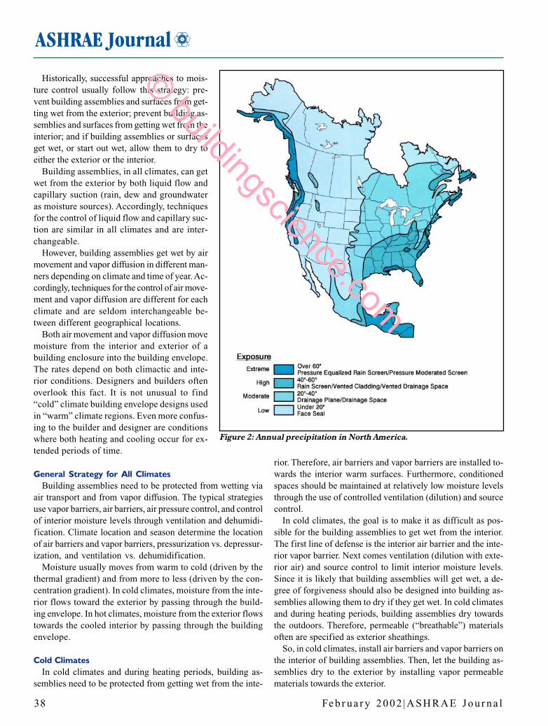
Environmental LoadsHygro-thermal regions, rain exposure
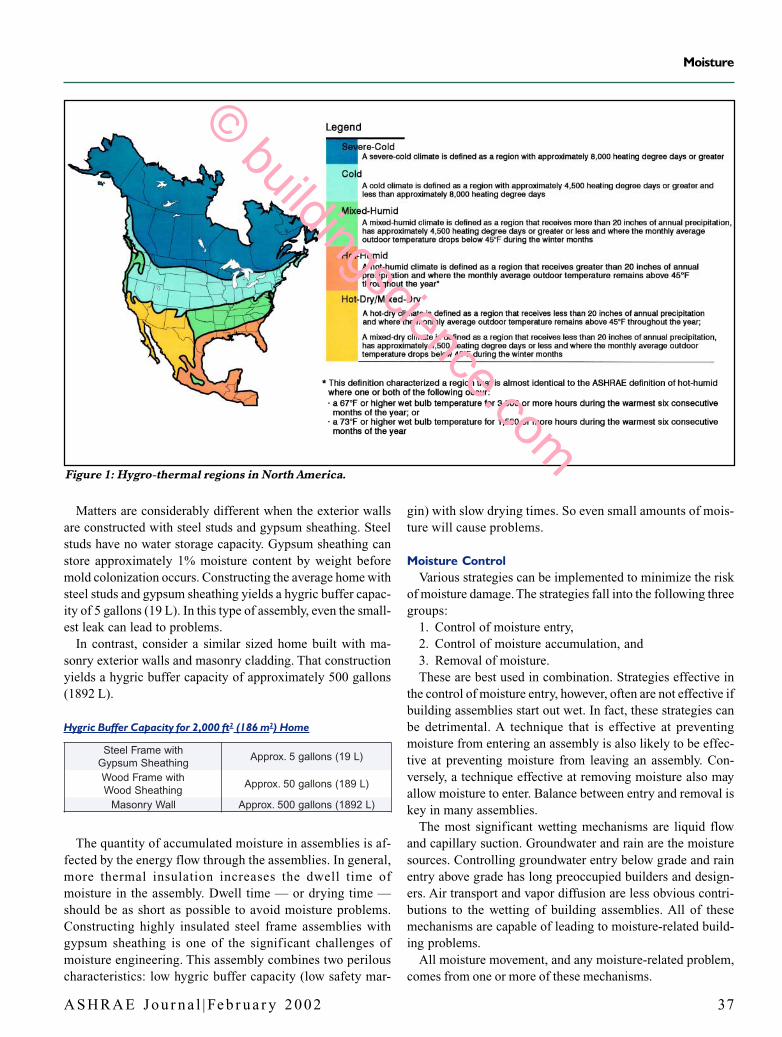
zones and interior climate classes areenvironmental loads used in applyingmoisture engineering to building enve-lopes and mechanical systems. Figure 1shows hygro-thermal regions and Figure2 shows rain exposure zones for NorthAmerica. Table 1 describes interior cli-mate classes.
words, the moisture storage capacity orhygric buffer capacity of most exteriorwood frame walls with wood-basedsheathings is approximately 10%. Ifmoisture accumulates beyond about 16%by weight, wood surfaces are likely todevelop mold.
In the average home approximately4,000 to 5,000 lbs (1814 to 2267 kg) ofwood are in the exterior walls. This yieldsa hygric buffer capacity of approximately400 to 500 lbs (181 to 226 kg) of wateror approximately 45 to 50 gallons (170to 189 L). From a performance perspec-tive, the average home can easily accom-modate 45 to 50 gallons (170 to 189 L)of water via hygric redistribution. Mostwater leaks are not a problem because ofthis large capacity to store water.
IssalCdetaredoMerutarepmeT•
dellortnocnUerusserPropaV•• dellortnocnUerusserPriA
IIssalCdellortnoCerutarepmeT•
• detaredoMerusserPropaV• detaredoMerusserPriA
IIIssalCdellortnoCerutarepmeT•
• dellortnoCerusserPropaV• dellortnoCerusserPriATable 1: Interior climate classes.
Copyright 2002, American Society of Heating, Refrigerating and Air-Conditioning Engineers, Inc. (www.ashrae.org).Reprinted by permission from ASHRAE Journal, February 2002. This article may not be copied nor distributed in eitherpaper or digital form without ASHRAE’s permission.
A S H R A E J o u r n a l | Fe b r u a r y 2 0 0 2 37
Moisture
Matters are considerably different when the exterior wallsare constructed with steel studs and gypsum sheathing. Steelstuds have no water storage capacity. Gypsum sheathing canstore approximately 1% moisture content by weight beforemold colonization occurs. Constructing the average home withsteel studs and gypsum sheathing yields a hygric buffer capac-ity of 5 gallons (19 L). In this type of assembly, even the small-est leak can lead to problems.
In contrast, consider a similar sized home built with ma-sonry exterior walls and masonry cladding. That constructionyields a hygric buffer capacity of approximately 500 gallons(1892 L).
Hygric Buffer Capacity for 2,000 ft2 (186 m2) Home
htiwemarFleetSgnihtaehSmuspyG
)L91(snollag5.xorppA
htiwemarFdooWgnihtaehSdooW
)L981(snollag05.xorppA
llaWyrnosaM )L2981(snollag005.xorppA
The quantity of accumulated moisture in assemblies is af-fected by the energy flow through the assemblies. In general,more thermal insulation increases the dwell time ofmoisture in the assembly. Dwell time — or drying time —should be as short as possible to avoid moisture problems.Constructing highly insulated steel frame assemblies withgypsum sheathing is one of the significant challenges ofmoisture engineering. This assembly combines two perilouscharacteristics: low hygric buffer capacity (low safety mar-
gin) with slow drying times. So even small amounts of mois-ture will cause problems.
Moisture ControlVarious strategies can be implemented to minimize the risk
of moisture damage. The strategies fall into the following threegroups:
1. Control of moisture entry,2. Control of moisture accumulation, and3. Removal of moisture.These are best used in combination. Strategies effective in
the control of moisture entry, however, often are not effective ifbuilding assemblies start out wet. In fact, these strategies canbe detrimental. A technique that is effective at preventingmoisture from entering an assembly is also likely to be effec-tive at preventing moisture from leaving an assembly. Con-versely, a technique effective at removing moisture also mayallow moisture to enter. Balance between entry and removal iskey in many assemblies.
The most significant wetting mechanisms are liquid flowand capillary suction. Groundwater and rain are the moisturesources. Controlling groundwater entry below grade and rainentry above grade has long preoccupied builders and design-ers. Air transport and vapor diffusion are less obvious contri-butions to the wetting of building assemblies. All of thesemechanisms are capable of leading to moisture-related build-ing problems.
All moisture movement, and any moisture-related problem,comes from one or more of these mechanisms.
Figure 1: Hygro-thermal regions in North America.
© buildingscience.com
38 Fe b r u a r y 2 0 0 2 | A S H R A E J o u r n a l
Historically, successful approaches to mois-ture control usually follow this strategy: pre-vent building assemblies and surfaces from get-ting wet from the exterior; prevent building as-semblies and surfaces from getting wet from theinterior; and if building assemblies or surfacesget wet, or start out wet, allow them to dry toeither the exterior or the interior.
Building assemblies, in all climates, can getwet from the exterior by both liquid flow andcapillary suction (rain, dew and groundwateras moisture sources). Accordingly, techniquesfor the control of liquid flow and capillary suc-tion are similar in all climates and are inter-changeable.
However, building assemblies get wet by airmovement and vapor diffusion in different man-ners depending on climate and time of year. Ac-cordingly, techniques for the control of air move-ment and vapor diffusion are different for eachclimate and are seldom interchangeable be-tween different geographical locations.
Both air movement and vapor diffusion movemoisture from the interior and exterior of abuilding enclosure into the building envelope.The rates depend on both climactic and inte-rior conditions. Designers and builders oftenoverlook this fact. It is not unusual to find“cold” climate building envelope designs usedin “warm” climate regions. Even more confus-ing to the builder and designer are conditionswhere both heating and cooling occur for ex-tended periods of time.
General Strategy for All ClimatesBuilding assemblies need to be protected from wetting via
air transport and from vapor diffusion. The typical strategiesuse vapor barriers, air barriers, air pressure control, and controlof interior moisture levels through ventilation and dehumidi-fication. Climate location and season determine the locationof air barriers and vapor barriers, pressurization vs. depressur-ization, and ventilation vs. dehumidification.
Moisture usually moves from warm to cold (driven by thethermal gradient) and from more to less (driven by the con-centration gradient). In cold climates, moisture from the inte-rior flows toward the exterior by passing through the build-ing envelope. In hot climates, moisture from the exterior flowstowards the cooled interior by passing through the buildingenvelope.
Cold ClimatesIn cold climates and during heating periods, building as-
semblies need to be protected from getting wet from the inte-
rior. Therefore, air barriers and vapor barriers are installed to-wards the interior warm surfaces. Furthermore, conditionedspaces should be maintained at relatively low moisture levelsthrough the use of controlled ventilation (dilution) and sourcecontrol.
In cold climates, the goal is to make it as difficult as pos-sible for the building assemblies to get wet from the interior.The first line of defense is the interior air barrier and the inte-rior vapor barrier. Next comes ventilation (dilution with exte-rior air) and source control to limit interior moisture levels.Since it is likely that building assemblies will get wet, a de-gree of forgiveness should also be designed into building as-semblies allowing them to dry if they get wet. In cold climatesand during heating periods, building assemblies dry towardsthe outdoors. Therefore, permeable (“breathable”) materialsoften are specified as exterior sheathings.
So, in cold climates, install air barriers and vapor barriers onthe interior of building assemblies. Then, let the building as-semblies dry to the exterior by installing vapor permeablematerials towards the exterior.
Figure 2: Annual precipitation in North America.
© buildingscience.com

A S H R A E J o u r n a l | Fe b r u a r y 2 0 0 2 39
Moisture
Figure 4: Classic hot-humid climate wall assembly.
periods, and from the exterior towards the interior during cool-ing periods. This approach requires both air pressure controland interior moisture control. The location of the air barriercan be towards the interior (sealed interior gypsum board), ortowards the exterior (sealed exterior sheathings or buildingwraps).
2. Installing the vapor barrier roughly in the thermal “middle”of the assembly. This is typically accomplished by installingimpermeable or semi-permeable insulating sheathing on theexterior of a frame cavity wall. For example, installing 1.5 in.(37 mm) of foil-faced insulating sheathing (approximately R10) on the exterior of a 2 × 6 frame cavity wall insulated withunfaced fiberglass batt insulation (approximately R 19). Thevapor barrier is the interior face of the exterior impermeableinsulating sheathing. If the wall assembly total thermal resis-tance is R 29 (R 19 plus R 10), the location of the vapor barrieris 66% of the way (thermally) towards the exterior (19/29 =0.66). In this approach air pressure control and using interiormoisture control would also be used. The location of the airbarrier can be towards the interior or exterior.
The advantage of this wall assembly is that an interior vaporbarrier is not necessary. In fact, locating a vapor barrier therewould be detrimental, as it would prevent the wall assemblyfrom drying towards the interior during cooling periods. Thewall assembly is more forgiving without the interior vaporbarrier than if one were installed.
Hot ClimatesHot and humid climates, humid weather and cooling peri-
ods present the opposite challenge. Building assemblies needto be protected from getting wet from the exterior, and theymust be allowed to dry towards the interior. Accordingly, airbarriers and vapor barriers are installed on the exterior of build-ing assemblies. Additionally, building assemblies must be al-lowed to dry towards the interior by using permeable interiorwall finishes and installing cavity insulations without vaporbarriers (unbacked fiberglass batts or blown cellulose or rockwool). Avoid any impermeable interior wall coverings such asvinyl wallpaper. Furthermore, conditioned spaces are main-tained at a slight positive air pressure with conditioned (dehu-midified) air to limit the infiltration of humid outdoor air.
Mixed ClimatesIn mixed climates, the situation becomes more complicated.
Building assemblies need to be protected from getting wetfrom both interior and exterior moisture, and must be allowedto dry to the exterior and interior. Two general strategies aretypically used:
1. Adopting a “flow-through” approach by using perme-able building materials on both the interior and exterior sur-faces of building assemblies to allow water vapor by diffusionto “flow-through” the building assembly without accumulat-ing. Flow will be from the interior to exterior during heating
Figure 3: Classic severe-cold climate wall assembly.
• Vapor diffusion retarder to the interior• Airflow retarder to the interior• Permeable exterior sheathing and permeable building paper
drainage plane• Ventilation provides air change (dilution) and also limits the
interior moisture levels
• Vapor diffusion retarder to the exterior• Airflow retarder to the exterior• Pressurization of conditioned space• Impermeable exterior sheathing also acts as drainage plane• Permeable interior wall finish• Interior conditioned space is maintained at a slight positive
air pressure with respect to the exterior to limit infiltration ofexterior, hot, humid air
• Air conditioning also provides dehumidification (moisture re-moval) from interior
© buildingscience.com

40 Fe b r u a r y 2 0 0 2 | A S H R A E J o u r n a l
Barriers and RetardersVapor Barriers and Vapor Retarders
The unit of measurement typically used in characterizingthe water vapor permeability of materials is the “perm.” Ma-terials can be separated into three general classes based ontheir permeability:
sreirraBropaVsaotderrefeRelbaemrepmIropaV sreirraBropaVsaotderrefeRelbaemrepmIropaV sreirraBropaVsaotderrefeRelbaemrepmIropaV sreirraBropaVsaotderrefeRelbaemrepmIropaV sreirraBropaVsaotderrefeRelbaemrepmIropaV
sselromrep1
sredrateRropaVsaotderrefeR—elbaemrePropaV-imeS sredrateRropaVsaotderrefeR—elbaemrePropaV-imeS sredrateRropaVsaotderrefeR—elbaemrePropaV-imeS sredrateRropaVsaotderrefeR—elbaemrePropaV-imeS sredrateRropaVsaotderrefeR—elbaemrePropaV-imeS
smrep01nahtsseldnamrep1nahterom
lbahtaerBsaotderrefeRelbaemrePropaV lbahtaerBsaotderrefeRelbaemrePropaV lbahtaerBsaotderrefeRelbaemrePropaV lbahtaerBsaotderrefeRelbaemrePropaV lbahtaerBsaotderrefeRelbaemrePropaV e
eromrosmrep01
Materials that are generally classed as impermeable towater vapor are: Rubber membranes, polyethylene film,glass, aluminum foil, sheet metal, oil-based paints, vinylwall coverings, and foil-faced insulating sheathings.
Materials that are generally classed as semi-vapor perme-able to water vapor are: plywood, OSB, unfaced expandedpolystyrene (EPS), fiberfaced isocyanurate, heavy asphaltimpregnated building papers, the paper and bitumen facingon most fiberglass batt insulation and most latex-basedpaints.
Materials that are generally classed as permeable to watervapor are: unpainted gypsum board and plaster, unfacedfiberglass insulation, cellulose insulation, unpainted stucco,lightweight asphalt impregnated building papers, asphalt
impregnated fiberboard, exterior gypsum sheathings, cementsheathings, and “housewraps.”
Air Barriers and Air RetardersThe physical properties that distinguish air barriers from
other materials are the ability to resist airflow and air pres-sure. Air barriers are typically systems of materials that com-pletely enclose the air within a building. Continuity of airbarrier systems at holes, openings and penetrations of thebuilding envelope is a key performance parameter.
Air barriers must resist the air pressure differences that acton them. Rigid materials such as gypsum board, exteriorsheathing materials such as plywood and OSB and supportedfilms such as “housewraps” installed over exterior sheath-ing are effective air barriers if their joints are sealed. Theirrigidity aids their ability to resist air pressure differences.Often, rubber or bitumen-based membranes are adhered tomasonry or sheathing materials to create an air barrier sys-tem. These rubber or bitumen-based membranes are alsoimpermeable and are therefore also vapor barriers.
Not all air barriers are vapor barriers and not all vaporbarriers are air barriers.
Air barriers typically define the location of the “pressureboundary” of the building envelope. The pressure bound-ary is defined as the location where 50% or more of the airpressure drop across an assembly occurs.
Materials or systems that reduce airflow or control airflowbut do not resist 50% or more of the air pressure drop acrossan assembly are called air retarders.
Suggestions for Moisture Engineering SpecificationsGeneral
• Soil surfaces shall be graded away from below-grade enve-lope surfaces.
• Materials next to below-grade envelope surfaces shall befree draining and shall connect to a subgrade drainage systemthrough a filter media that will prevent fines buildup in thedrainage system.
• A clay cap or other water-flow resistant surface layer shallbe installed to prevent surface water from draining into thefree-draining material next to below-grade envelope surfaces.
• Below-grade surfaces shall be provided with a damp-proof-ing layer or coating that will be effective as a capillary break.
• Surfaces subject to wind-driven rain or snow shall be pro-vided with a drainage plane or layer that will prevent rainwetting of internal materials.
• Indoor dew point shall be maintained below the coldestsurface temperature inside of the building envelope air barrier.
• Indoor relative humidity shall be maintained below 70%as measured at the coldest indoor surface.
• Building envelope assemblies should include at leastone air barrier and one vapor retarder or vapor barriersurface.
• Crawl space assemblies should have a continuous im-permeable ground cover that functions as both an air barrierand vapor barrier.
Cold-Climate Requirements• Locate vapor barriers towards the interior of building
assemblies. Avoid vapor barriers located towards the exterior.• Where low permeance exterior sheathings are used,
temperature of condensing surfaces under heating conditionsshould be controlled (use of insulating sheathings, externalinsulation) as well as by limiting the indoor vapor pressures.
• Provide air barrier systems that limit air movement fromthe interior into the exterior walls and roofs.
• Provide secondary air barriers that limit wind washingfrom the exterior.
• During the coldest portion of the heating season, keep theindoor dew point below 35°F (2°C).
© buildingscience.com

A S H R A E J o u r n a l | Fe b r u a r y 2 0 0 2 41
Moisture
• Airflow retarder to the interior• Permeable interior wall finish• Interior conditioned space is maintained at a slight positive
air pressure with respect to the exterior to limit the infiltra-tion of exterior moisture-laden air during cooling
• Ventilation provides air change (dilution) and also limits theinterior moisture levels during heating
• Air conditioning/dehumidification limits the interior mois-ture levels during cooling
• Impermeable exterior sheathing also acts as drainage plane
• Permeable interior surface and finish and permeableexterior sheathing and permeable building paper drainageplane
• Interior conditioned space is maintained at a slight positiveair pressure with respect to the exterior to limit the infiltrationof exterior moisture-laden air during cooling
• Ventilation provides air change (dilution) and also limits theinterior moisture levels during heating
• Air conditioning/dehumidification limits the interior mois-ture levels during cooling
• Allow wet or moist materials used in construction to drytowards the outdoors.
Mixed-Climate Requirements• Use a “flow-through” approach to vapor diffusion control.• Where low permeance exterior sheathings are used, tem-
perature of condensing surfaces under heating conditionsshould be controlled (use of insulating sheathings, externalinsulation) as well as interior vapor pressures.
• Provide air barrier systems that limit air movement fromthe interior.
• Provide air barrier systems that limit air movement fromthe exterior.
• During the coldest portion of the heating season, keep theindoor dew point below 40°F (4°C).
• During the cooling season, keep the indoor dew pointbelow 55°F (13°C).
Hot, Humid Climate Requirements• Pressurize conditioned and interstitial spaces with air dried
below a dew point of 55°F (13°C).• Locate vapor barriers toward the exterior of building as-
Figure 6: Vapor diffusion retarder in the middle of the wall.
Figure 5: Classic flow-through wall assembly.
semblies. Avoid vapor barriers such as vinyl wall coveringstoward the interior of building assemblies.
• Provide air barrier systems that limit air infiltration andwind washing from the exterior.
• Provide adequate dehumidification capacity under partload conditions when sizing air-conditioning equipment.
• Dehumidify makeup air to a dew point of 55°F (13°C).before it is introduced.
• Keep the indoor dew point below 55°F (13°C).• Insulate cold water piping and cold duct distribution sys-
tems.• Do not overcool interior spaces.• Design the exterior wall so that wet or moist materials
used in construction can dry towards the interior.
BibliographyHutcheon, N.B. 1953. “Fundamental considerations in the
design of exterior walls for buildings.” Engineering Journal36(1):687–698.
© buildingscience.com


![Paper Title - ASHRAE Library/Conferences... · Paper Title Author Name, PhD, PE Author Name Author Name, PE [ASHRAE Affiliation] Student Member ASHRAE Fellow ASHRAE ABSTRACT HEADING](https://static.fdocuments.net/doc/165x107/5f71b39d1a193b0c14194175/paper-title-ashrae-libraryconferences-paper-title-author-name-phd-pe-author.jpg)