WHEELED VEHICLE STEERING SYSTEMS - · PDF fileUS ARMY LIGHT WHEEL ... INTRODUCTION TO WHEELED...
52
SUBCOURSE EDITION OD1007 A US ARMY ORDNANCE CENTER AND SCHOOL WHEELED VEHICLE STEERING SYSTEMS
-
Upload
hoangduong -
Category
Documents
-
view
218 -
download
3
Transcript of WHEELED VEHICLE STEERING SYSTEMS - · PDF fileUS ARMY LIGHT WHEEL ... INTRODUCTION TO WHEELED...
SUBCOURSE EDITION OD1007 A
US ARMY ORDNANCE CENTER AND SCHOOL
WHEELED VEHICLE STEERING SYSTEMS


US ARMY LIGHT WHEEL VEHICLE MECHANIC MOS 63B SKILL LEVEL 3 COURSE
WHEELED VEHICLE STEERING SYSTEMS
SUBCOURSE NO. OD 1007
US Army Ordnance Center and School Aberdeen Proving Ground, Maryland
Five Credit Hours
GENERAL
The Wheeled Vehicle Steering Systems subcourse, par t of the Light Wheel Vehicle Mechanic MOS 63B Skill Level 3 Course, is d esigned to teach the knowledge necessary to develop the skills for servi cing and maintaining steering systems. Information is provided on the f undamentals and inspection procedures for wheeled vehicle steering systems. The subcourse is presented in two lessons, each corresponding to a terminal objective as indicated below. Lesson 1: FUNDAMENTALS OF STEERING SYSTEMS TASK: Describe the fundamentals of steering systems . CONDITIONS: Given information on the construction, operation, and inspection of mechanical steering linkages and the principles of steering geometry. STANDARDS: Answer 70 percent of the multiple-choice test items covering fundamentals of steering systems. Lesson 2: FUNDAMENTALS OF POWER STEERING TASK: Describe the fundamentals of power steering s ystems. CONDITIONS: Given information on the principles, op eration, construction, and inspection of power steering systems. STANDARDS: Answer 70 percent of the multiple-choice test items covering fundamentals of power steering systems.
*** IMPORTANT NOTICE ***
THE PASSING SCORE FOR ALL ACCP MATERIAL IS NOW 70%.
PLEASE DISREGARD ALL REFERENCES TO THE 75% REQUIREMENT.
i
TABLE OF CONTENTS Section Page TITLE PAGE ........................................ .............. i TABLE OF CONTENTS ................................. .............. ii ADMINISTRATIVE INSTRUCTIONS ....................... .............. iv GRADING AND CERTIFICATION INSTRUCTIONS ............ .............. iv INTRODUCTION TO WHEELED VEHICLE STEERING SYSTEMS .. .............. v Lesson 1: FUNDAMENTALS OF STEERING SYSTEMS Learning Event 1: Describe the Principles of Steering and the Construction and Operation of Mechanical Steering Gears and Linkages ........ .......... 1 Learning Event 2: Describe the Principles of Wheel Alignment ............................... .......... 15 Learning Event 3: Describe Inspection Procedures for Mechanical Steering Systems ....... .......... 24 Practice Exercise ................................ .......... 28 Answers to Practice Exercise ..................... .......... 30 Lesson 2: FUNDAMENTALS OF POWER STEERING Learning Event 1: Describe the Construction and Operation of Power Steering Systems .......... .......... 31 Learning Event 2: Describe the Inspection and Troubleshooting Procedures for Power Steering Systems ................................. .......... 38 Practice Exercise ................................ .......... 44 Answers to Practice Exercise ..................... .......... 46 ii

THIS PAGE INTENTIONALLY LEFT BLANK
iii

INTRODUCTION TO WHEELED VEHICLE STEERING SYSTEMS A vehicle is not much use if it cannot be steered o r guided. The act of guiding the vehicle is called steering. Wheeled ve hicles are steered by aiming or pointing the wheels in the direction we w ant the vehicle to go. The driver of a car or truck guides it by turning t he steering wheel. The steering system of cars and trucks consists of leve rs, links, rods, and a gearbox and sometimes a hydraulic system that assis ts the driver's steering effort. The steering system is of critical importance in th e safe operation of the vehicle. There must be no looseness between the st eering wheel and the front wheels if the driver is to keep control over the direction the wheels point. The tires must meet the road at the correct angle to get good traction and to prevent unnecessary tire wear. Als o, the driver should be able to hold the wheels in the straight-ahead posit ion and change them to the right or left with very little effort. For you, the student, a study of steering introduce s many new words, parts, ideas, and theories. The study includes some math, physics, and hydraulics. This subcourse will provide you with a thorough und erstanding of the design, construction, operation, and unit maintenance of st eering systems. Math, physics, and hydraulics are covered right in the te xt where they apply. When you see a new word, a new part, a new idea, or a new theory, be sure you know what it means, how it works, and why it wo rks before you continue. iv

Lesson 1/Learning Event 1
LESSON 1 FUNDAMENTALS OF STEERING SYSTEMS
TASK Describe the fundamentals of steering systems. CONDITIONS Given information about the construction and operat ion of mechanical steering gears and steering linkages and the princi ples of steering geometry. STANDARDS Answer 70 percent of the multiple-choice test items covering fundamentals of steering systems. REFERENCES TM 9-8000 Learning Event 1: DESCRIBE THE PRINCIPLES OF STEERING AND THE CONSTRUCTION AND OPERATION OF MECHANICAL STEERING GEARS AND LINKAGES One of the most interesting features on a wheeled v ehicle is the steering system. The steering system consists of all the pa rts necessary to make the front wheels turn in the direction we wish to go. These parts include a steering wheel, a gearbox, and all linkages and lev ers needed to control the front wheels. Steering systems are carefully designed so that the driver can, without too much effort, keep the vehicle going straight ahead or turn it to the right or left. The driver must be able to easily overcom e the tendency of the front wheels to go to the right or left as a result of striking holes in the road, rocks, stumps, or other obstructions. Obstru ctions try to stop the wheel that strikes them, while the other front whee l tries to keep rolling, which causes the vehicle to turn in the direction o f the obstruction. This is called road shock. Road shock tries to jerk the steering wheel out of the driver's hands. Hitting obstructions makes it difficult to control the vehicle, and steering systems are designed to reduc e the shock caused by striking obstructions.
1
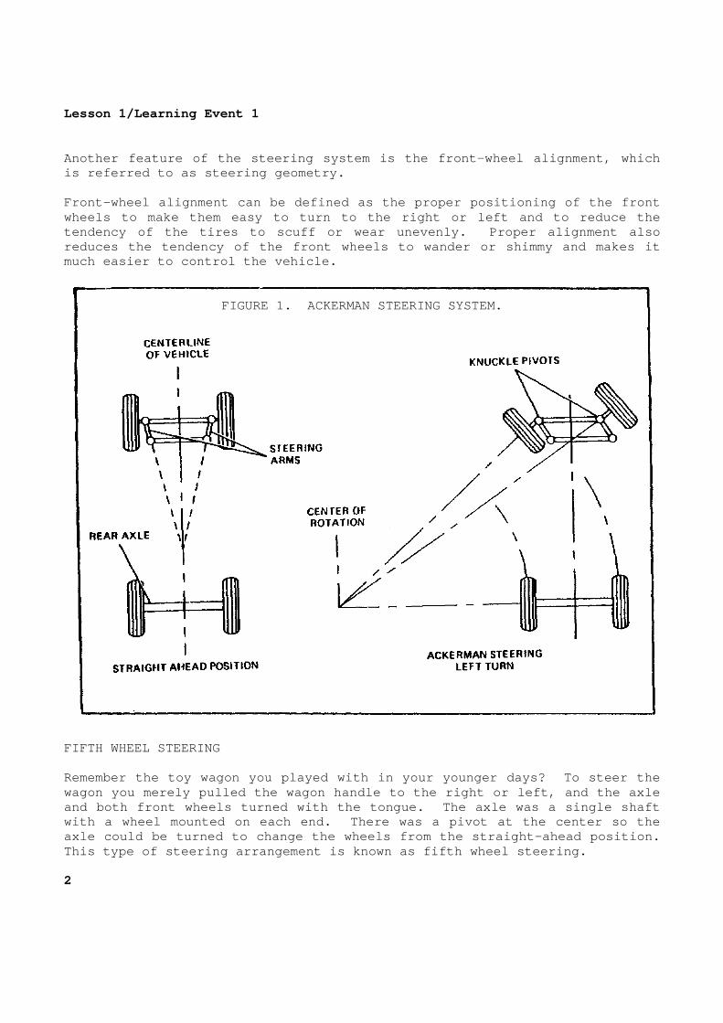
Lesson 1/Learning Event 1 Another feature of the steering system is the front -wheel alignment, which is referred to as steering geometry. Front-wheel alignment can be defined as the proper positioning of the front wheels to make them easy to turn to the right or le ft and to reduce the tendency of the tires to scuff or wear unevenly. P roper alignment also reduces the tendency of the front wheels to wander or shimmy and makes it much easier to control the vehicle.
FIGURE 1. ACKERMAN STEERING SYSTEM. FIFTH WHEEL STEERING Remember the toy wagon you played with in your youn ger days? To steer the wagon you merely pulled the wagon handle to the rig ht or left, and the axle and both front wheels turned with the tongue. The axle was a single shaft with a wheel mounted on each end. There was a pivo t at the center so the axle could be turned to change the wheels from the straight-ahead position. This type of steering arrangement is known as fifth wheel steering. 2

Lesson 1/Learning Event 1 Fifth wheel steering is commonly used on towed vehi cles, such as semitrailers pulled by tractor-trucks. The lower p art of the steering pivot or fifth wheel is mounted over the center, and slig htly to the front, of the rear axle of the tractor. It has a kingpin lock to hold the kingpin or pivot pin of the semitrailer in the center of the f ifth wheel. Usually, the lower fifth wheel is mounted on the tr actor with two pivot shafts. One shaft is positioned crosswise to the t ractor; the other, lengthwise. This allows the lower fifth wheel to t ip at various angles to the tractor chassis, keeping the bearing surfaces o f upper and lower halves of the fifth wheel in firm contact as the tractor a nd trailer travel over unlevel roads. The upper part of the fifth wheel consists of a pic kup plate and kingpin secured to the bottom front of the semitrailer. A groove around the kingpin allows engagement of the kingpin lock. When the semitrailer is connected to the tractor, t he bottom of the trailer is higher than the tractor wheels. This is necessa ry because, as the truck and trailer make a turn, the entire rear axle and w heel assembly pivot under the front of the trailer frame. On a very sharp tu rn, the wheel on the inside of the turn will move to about the middle un der the trailer chassis. Clearance must be provided for the wheels. 3

Lesson l/Learning Event 1
FIGURE 2. FIFTH-WHEEL STEERING.
ACKERMAN STEERING The fifth-wheel method of steering is not suitable for steering a modern car or truck. The vehicle chassis would have to be too high off the ground to provide clearance for the front wheels. Cars and t rucks use a different front wheel arrangement. It is called the Ackerman steering method. With this arrangement, the axle is held at a right angle to the vehicle frame and cannot pivot. The wheels change from the straight-ahead position independently on separate pivot pins or knuckle piv ots at the ends of the axle. We will be discussing only the Ackerman steering me thod during the rest of this lesson, so let's clarify the terms that we wil l be using in regard to wheel movements with this method. When we say "the wheels pivot," we mean that they are changed in relation to the straight-a head position when making a right or left turn. When we say "the wheels rota te," we mean that they turn on their spindles as the vehicle rolls forward or backward. 4

Lesson l/Learning Event 1
FIGURE 3. CENTER STEERING LINKAGE.
STEERING LINKAGE To make a turn, the driver of a car or truck turns the steering wheel to the right or left. Because each front wheel has its ow n separate steering pivot, a considerable amount of linkage is needed t o transfer the steering wheel movements to both wheels. The steering wheel is located at the top of a steering column. As it is turned, a steering gea r at the bottom of the column is operated. The steering linkage is all of the levers, rods, arms, and links used to connect the steering gear to the front wheels. There is wide variation in the amount of steering linkage on different vehicles. Most vehicles with front axle suspension have a steering linkage arrangement like the one shown in Figure 3. The linkage consis ts of the pitman arm, which is splined to the output shaft or pitman arm shaft of the steering gear; the drag link, which links the pitman arm to the steering knuckle arm of the left front wheel; two steering knuckle arms, one secured to each of the front-wheel spindles; and the tie rod, which li nks the two front-wheel steering arms together. The linkage may be arrange d so that the tie rod is in front of the axle or behind it.
5

Lesson 1/Learning Event 1 Rotary motion of the steering wheel causes the pitm an arm shaft to move back and forth in an arc, so that the drag link moves ba ck and forth in a straight line. The drag link transmits the movemen t to the left steering arm to pivot the left wheel spindle and wheel back and forth on the steering knuckle pivots. Pivot movements of the left wheel are transmitted to the right wheel by the tie rod. The drag link and tie rod are fastened to the pitma n and steering arms by adjustable, ball-socket joints that permit swivelin g action. Ball-type studs are secured to the pitman arm and the left st eering arm. A housing at each end of the drag link receives the balls. Ball -sockets, coil springs, spring seats, and a screw plug in the housings hold the balls. The screw plug can be screwed in or out to tighten or loosen the joint. Lubrication fittings are provided for each joint. Shields hold the lubrication in and keep dirt out. The tie rod also uses ball-socket joints, but gener ally they are not adjustable. A spring holds the ball in its seat to prevent slack. The ball of a tie rod end has a tapered shank or stud that f its into a matching tapered hole in the steering arm. The end of the b all stud is threaded and drilled so it can be secured to the steering knuckl e arms with a nut and cotter key. Each tie rod is threaded and screwed onto the tie r od end. A clamp bolt prevents the tie rod from turning once the ends hav e been installed. One tie rod end and one end of the tie rod have lef t-hand threads, and the other tie rod end and the opposite end of the tie r od have right-hand threads. This is so the overall length of the tie rod assembly can be adjusted when aligning the front wheels without dis connecting either tie rod end. If the vehicle has independent front-wheel suspensi on instead of an axle, the steering linkage arrangement is different. Two tie rods are required so each wheel can be raised and lowered without affect ing the steering of the other. Many different linkage arrangements are use d with independent suspension. Some are quite simple, with the linkag e consisting of the pitman arm, two tie rods, and the steering arms. 6

Lesson 1/Learning Event 1 Other common arrangements add an idler arm and drag link. In these arrangements the idler arm is mounted on the right frame rail by a bracket parallel to the pitman arm. The drag link connects the pitman arm and idler arm so that moving the steering wheel causes both a rms to swing in the same arc. Each steering arm is linked to the drag link by a separate tie rod. In this arrangement, the drag link may be called a relay rod, pitman arm-to-idler arm rod, and so forth. Usually, the length of both tie rods can be adjuste d independently when aligning the front wheels. The ends on the drag li nks and tie rods of vehicles with independent wheel suspension are usua lly not adjustable. On some late-model cars, tie rod ends are lubricated f or life when manufactured and do not contain lubricating fittings. Either threaded or rubber bushings are used at the idler arm-to-idler arm bracket pivot. Threaded-type bushings contain both internal and external threads. The external threads are generally right- hand threads and are screwed into, and tightened in, a threaded hole in either the idler arm or its bracket. The internal threads are generally le ft-hand threads and are screwed onto the threaded end of the arm or bracket until it bottoms and then backed up one-half to one turn. This leaves t he idler arm free to pivot on the inner threads of the bushing. STEERING GEAR With the steering wheel coupled directly to the pit man arm by a shaft, it would be very hard for the driver to steer the vehi cle. Something must be used between the steering wheel and pitman arm so t he driver can gain a mechanical advantage to make steering easier. This is the function of the steering gear. The principles of steering gears can be demonstrate d with a bolt and a nut in the following manner. Screw the nut to the midp oint of the threads on the bolt. Place the end of the bolt against a flat surface so it cannot move back and forth but can be rotated. Hold the n ut so it cannot rotate; then, turn the bolt. When the bolt is turned clock wise, the nut is pulled toward the bolt's head. When the bolt is turned co unterclockwise, the nut will be moved away from the bolt's head. Now, if we cut out a section of the nut, attach a s haft to it, and place it against the bolt, we can see how this principle is used in the steering gear. With this arrangement, turning the bolt back and forth will cause the nut section to swing back and forth, turning the sh aft with it.
7

Lesson 1/Learning Event 1 In a steering gear, the part that is like the bolt is called the worm. The worm is secured to the lower end of a shaft with th e steering wheel on the opposite end so that the worm and steering wheel tu rn together. The steering gear part that is like the section of a nu t is called the sector, and its shaft is called the pitman arm shaft. The pitman arm is splined to the pitman arm shaft. The steering gear worm (bolt) and the sector (nut s ection) are machined so that there is very little lash or clearance between their threads in the midposition. However, as the worm is turned to ste er the vehicle either to the right or the left, the amount of lash increases . This makes up for the unequal wear that occurs in normal use. Vehicles a re operated in the straight-ahead position most of the time, so most o f the wear is in the center of the steering gear worm. It requires 2 1/2 to 3 1/2 turns of the steering wh eel and worm to move the pitman arm shaft through its entire allowable movem ent, an arc of about 70 °. That pivots the front wheels from a hard turn in on e direction to a hard turn in the opposite direction. The steering wheel has to be turned farther because of the mechanical advantage gained by the w orm and sector. Most steering gears are designed so that they provide mo re mechanical advantage in the midposition than when turned to the extreme right or left, so they are said to have a "variable" ratio. Many different kinds of steering gears are used, bu t they all work in about the same manner. 8

Lesson 1/Learning Event 1
FIGURE 4. WORM AND SECTOR STEERING GEAR.
WORM AND SECTOR STEERING GEAR This type of steering gear looks a lot like our bol t and nut, but the sector of this type looks like a gear instead of a nut. T he teeth of the sector are machined in an arc, or curve, so that they actu ally look like a section of a gear. As the steering wheel and worm turn, the worm pivot s the sector and pitman arm shaft. The sector pivots through an arc of 70 ° because it is stopped at each extreme when it touches the steering gear hous ing. The worm is assembled between bearings, and some me ans is provided to adjust the bearings to control worm end play. The pitman arm shaft is fitted into the steering gear housing on bearings (generally th e bushing type, but roller-type bearings are sometimes used). A lash a djustment screw is also provided so that the sector can be moved closer to, or farther away from, the worm gear to control the backlash between the s ector and worm threads or teeth.
9

Lesson 1/Learning Event 1 The worm and sector steering gear is very simple in construction. This makes it cheap to build and easy to maintain. A di sadvantage is that it has a lot of friction because of the sliding action bet ween the worm and sector gear teeth.
FIGURE 5. WORM AND ROLLER STEERING GEAR.
WORM AND ROLLER STEERING GEAR The worm and roller steering gear is much like the worm and sector, but the sliding friction is changed to rolling friction so that less effort is required to turn the steering wheel. This is made possible by machining the sector teeth on a roller. Friction is reduced even more by mounting the roller on bearings in a saddle at the inner end of the pitman arm shaft. The worm has an hourglass shape, smaller in the cen ter than at the ends. The hourglass shape makes the roller stay in better contact with the worm teeth at the ends of the worm. 10

Lesson 1/Learning Event 1
FIGURE 6. CAM AND LEVER STEERING GEAR.
CAM AND LEVER STEERING GEAR In the cam and lever steering gear, the worm is kno wn as a cam. The inner end of the pitman arm shaft has a lever that contai ns a tapered stud. The stud engages in the cam so that the lever is moved back and forth when the cam is turned back and forth. When the tapered stud is fixed in the lever so that it can't rotate, there is sliding friction between it and the cam. Theref ore, on some vehicles with this type of steering gear, the stud is mounte d in bearings so that it rolls in the cam groove (threads) instead of slidin g. Some large trucks use a cam and twin-lever steering gear. This is nothing more than a cam and lever gear with two tapered stu ds instead of one. The studs may be fixed in the lever, or they may be mou nted on bearings.
11

Lesson 1/Learning Event 1
FIGURE 7. WORM AND NUT STEERING GEAR.
WORM AND BALL NUT STEERING GEAR Another form of steering gear is called the worm an d ball nut. In its operation, this one really acts like a bolt and a n ut. A nut is meshed with the worm and screws up and down when the worm is tu rned back and forth. These steering gears are also called the recirculat ing ball type. Both the nut and the worm have round-shaped threads that ste el balls fit in. The balls act as a bearing to reduce the friction betwe en the worm and nut. Ball guides on one side of the nut allow the balls to recirculate as the worm turns to screw the nut back and forth on the w orm. 12

Lesson 1/Learning Event 1 The nut has teeth on one side that mesh with the se ctor and turn the pitman arm shaft back and forth as the nut is moved back a nd forth. As with all the rest of the steering gears described, the end p lay of the worm and the backlash between the nut and sector teeth are adjus table.
FIGURE 8. RACK AND PINION STEERING GEAR.
RACK AND PINION TYPE In the rack and pinion steering system, the steerin g gear shaft has a pinion gear on the end that meshes with a long rack. The rack is connected to the steering arms by tie rods, which are adjustable to maintain proper toe angle. As the steering wheel is rotated, the pinio n gear on the end of the steering shaft rotates. The pinion moves the rack left and right to operate the steering linkage. Rack and pinion gears are us ed on small passenger vehicles where a high degree of precision steering is required. Their use on larger vehicles is limited.
13
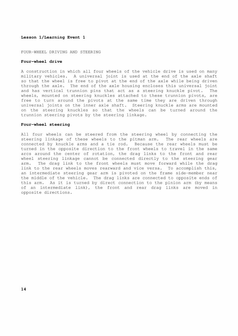
Lesson 1/Learning Event 1 FOUR-WHEEL DRIVING AND STEERING Four-wheel drive A construction in which all four wheels of the vehi cle drive is used on many military vehicles. A universal joint is used at th e end of the axle shaft so that the wheel is free to pivot at the end of th e axle while being driven through the axle. The end of the axle housing encl oses this universal joint and has vertical trunnion pins that act as a steeri ng knuckle pivot. The wheels, mounted on steering knuckles attached to th ese trunnion pivots, are free to turn around the pivots at the same time the y are driven through universal joints on the inner axle shaft. Steering knuckle arms are mounted on the steering knuckles so that the wheels can be turned around the trunnion steering pivots by the steering linkage. Four-wheel steering All four wheels can be steered from the steering wh eel by connecting the steering linkage of these wheels to the pitman arm. The rear wheels are connected by knuckle arms and a tie rod. Because t he rear wheels must be turned in the opposite direction to the front wheel s to travel in the same arcs around the center of rotation, the drag links to the front and rear wheel steering linkage cannot be connected directly to the steering gear arm. The drag link to the front wheels must move f orward while the drag link to the rear wheels moves rearward and vice ver sa. To accomplish this, an intermediate steering gear arm is pivoted on the frame side-member near the middle of the vehicle. The drag links are conn ected to opposite ends of this arm. As it is turned by direct connection to the pinion arm (by means of an intermediate link), the front and rear drag l inks are moved in opposite directions. 14

Lesson 1/Learning Event 2 Learning Event 2: DESCRIBE THE PRINCIPLES OF WHEEL ALIGNMENT It is not enough to merely place the front wheels o n spindles and steering knuckles so they can roll and so the driver can piv ot them to the right or left. The wheels must be pointed or aligned just r ight if the vehicle is to steer properly. Wheel alignment (steering geometry) is the position ing of the front wheels to best control the forces of gravity, friction, mo mentum, and centrifugal force. All of these forces tend to make steering d ifficult. Perfectly aligned wheels do not wander, weave, shim my, or scuff tires, yet they are easy to pivot when making a turn. In addi tion, the front wheels should straighten out if the driver releases the st eering wheel after turning a corner. To do all this, the front wheels and their pivot po ints are not positioned straight up and down or straight ahead. They are t ilted at various angles. There are five different angles involved in the ali gnment of the front wheels: caster, camber, kingpin inclination, toe-i n, and toe-out. Definitions of these angles and their effects are g iven in the following paragraphs.
15
Lesson 1/Learning Event 2
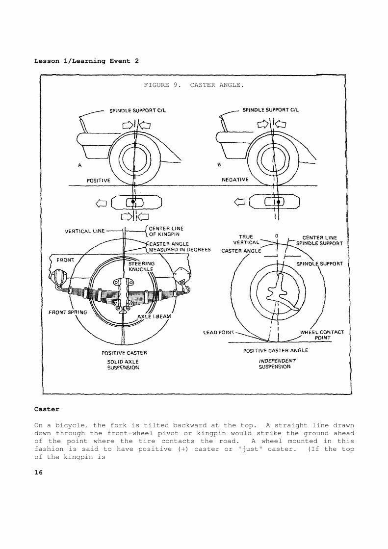
FIGURE 9. CASTER ANGLE.
Caster On a bicycle, the fork is tilted backward at the to p. A straight line drawn down through the front-wheel pivot or kingpin would strike the ground ahead of the point where the tire contacts the road. A w heel mounted in this fashion is said to have positive (+) caster or "jus t" caster. (If the top of the kingpin is 16

Lesson 1/Learning Event 2 tilted forward so a straight line drawn through it hits behind the point where the tire contacts the ground, the wheel is sa id to have negative (-) caster.) On a vehicle with axle suspension, caster is obtain ed by the axle being mounted so that the top of the steering knuckle or kingpin is tilted to the rear. On independent suspension, the upper pivot p oint is set to the rear of the lower pivot point. The caster angle is measured in degrees. The angle is shown by drawing one line straight up and down and then drawing a second line through the center of the kingpin or pivot points. The caster angle i s the angle formed at the point where the two lines cross as viewed from the side of the vehicle. From the above description of caster, we can say th at caster or positive caster is the backward tilt of the kingpin at the t op. Negative caster is just the reverse, with the kingpin tilted forward a t the top. Positive caster causes the vehicle to steer in the direction that it tends to go. This is called an automatic steering effect . For instance, the forward momentum of a vehicle tends to keep wheels with positive caster in the straight-ahead position. After rounding a turn , this causes the wheels to return to a straight-ahead position if the drive r releases the steering wheel. This automatic steering effect is also call ed self-righting action or self-centering action. The automatic steering effect of caster can be show n by picturing a bicycle with an excess amount of caster. As the wheel is p ushed forward, it resists movement; so it pulls back at the point where it co ntacts the road. Since the kingpin is pointed in front of the tire contact , the wheel pulling back tends to keep it in the straight-ahead position. Other forces besides forward momentum react with ca ster so that the automatic steering is not always perfectly straight ahead. Any force that is pushing on the side of the vehicle tends to pivo t the wheels in the direction of the force. For this reason, positive caster tends to cause a vehicle to steer down off a crowned road and in the direction of a crosswind. Some passenger cars are designed to hav e negative caster so that just the opposite will happen; that is, they will t end to steer up a crowned road and against or into a crosswind.
17
Lesson 1/Learning Event 2
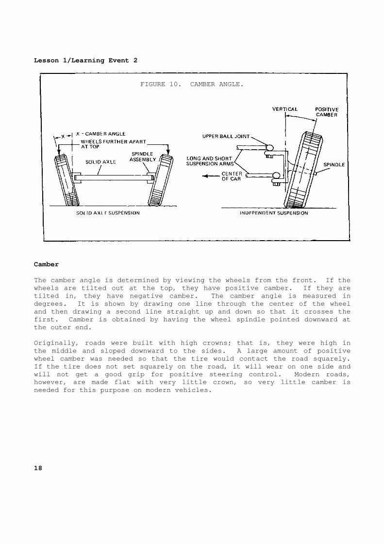
FIGURE 10. CAMBER ANGLE.
Camber The camber angle is determined by viewing the wheel s from the front. If the wheels are tilted out at the top, they have positiv e camber. If they are tilted in, they have negative camber. The camber a ngle is measured in degrees. It is shown by drawing one line through t he center of the wheel and then drawing a second line straight up and down so that it crosses the first. Camber is obtained by having the wheel spin dle pointed downward at the outer end. Originally, roads were built with high crowns; that is, they were high in the middle and sloped downward to the sides. A lar ge amount of positive wheel camber was needed so that the tire would cont act the road squarely. If the tire does not set squarely on the road, it w ill wear on one side and will not get a good grip for positive steering cont rol. Modern roads, however, are made flat with very little crown, so v ery little camber is needed for this purpose on modern vehicles. 18

Lesson 1/Learning Event 2 Some camber is generally desirable, even with flat roads, because it moves the point of contact between the tire and the road more directly under, and closer to, the steering knuckle pivot. This makes the wheels easier to pivot and reduces the amount of road shock that is sent to the vehicle suspension and steering linkage when the wheels hit bumps. It also places most of the load on the large inner wheel bearing. The amount of camber must be carefully considered w hen designing a vehicle to avoid some bad effects. If you ever rolled a ti re by hand, you soon learned that you did not have to turn the tire in o rder to turn a corner. All you had to do was to tilt (camber) the tire to one side, and it rolled around the corner like a cone. This is not desirab le for the wheels of a vehicle. The cone effect of positive camber tries to pivot the wheels out on a vehicle.
FIGURE 11. KINGPIN INCLINATION.
Kingpin inclination In addition to the caster tilt, the kingpin is also tilted inward at the top. This inward tilt is called kingpin inclinatio n. It is determined by viewing the kingpin or pivot points from the front. Kingpin inclination is another alignment factor that is
19

Lesson 1/Learning Event 2 measured in degrees. It can be shown by drawing tw o lines that cross to form an angle. One line passes through the center of the pivot points or kingpin and the other line is straight up and down. Notice that the kingpin is tilted in the opposite d irection from the cambered wheel. Proper kingpin inclination can red uce the amount of camber needed to place the point of tire contact with the ground under the steering knuckle pivot. If the front wheels are aligned pro perly, lines drawn through the center of the cambered wheel and the ki ngpin should hit the ground close to where the tire contacts the ground. (The combination of the kingpin inclination angle and the wheel camber angl e is known as the included angle.) 20

Lesson 1/Learning Event 2
FIGURE 12. TOE-IN.
Toe-in The front wheels should roll perfectly straight dow n the road, or else the tires scuff (slip sideways), wearing the tread rapi dly. As the vehicle moves ahead, the wheels resist movement and hold ba ck on the spindles. This force, plus that of the cone effect of camber wheel s, causes the wheels to try to pivot outward.
21

Lesson 1/Learning Event 2 That is, the left wheel tries to pivot to the left and the right wheel to the right. The wheels are able to pivot out to som e extent because the steering knuckles and tie rod ends must have a slig ht amount of clearance to permit easy steering. To offset this, the wheels a re aligned with a slight amount of toe-in. Toed-in wheels are closer together at the front tha n at the rear. Toe-in is measured in inches. The amount is found by measuri ng the distance between the front wheels, first at the front outer edges of the tires and then at their rear outer edges. The amount of toe-in is th e difference in the two measurements, which is usually about 1/32 inch to 1 /8 inch. If the wheels are closer together in the rear than in the front, they are said to be toed-out. The amount of toe-in can be adjusted by short ening or lengthening the adjustable tie rod. Ideally, the toe-in, measured with the vehicle stan ding still, should exactly equal the amount the wheels pivot outward w hen the vehicle runs at cruising speed. Then, the wheels will roll perfect ly straight ahead at cruising speed with no side slippage. Toe-out Side slippage of the tires must also be considered when turning a corner, to ensure positive steering control and to prevent exc essive tire wear. Each wheel must be at a 90 ° angle to the center of rotation if it is to roll easily and not scuff the tread of the tire. This is no problem for-fifth wheel steering. Pivot ing the axle assembly moves the front wheel at the outer edge of the turn ing radius ahead of the inner wheel, and the 90 ° angle is obtained. With Ackerman steering, however, the wheels must toe-out on a turn. With Ackerman steering, when turning a corner, one straight line cannot be extended from the center of both front wheels. Ins tead, two lines must be extended at different angles in order to pass throu gh the center of the wheels. For both wheels to be at a 90 ° angle to the center of rotation, the inner wheel must pivot more than the outer wheel. (The exact difference in the amount that the wheels should pivot is the valu e of the angle formed by the lines extended from the center of rotation thro ugh the center of the front wheels. For instance, if the lines form a 3° angle, the inner wheel must pivot 3 ° more than the outer wheel.) 22

Lesson 1/Learning Event 2 Also, the size of the circles that the front wheels travel shows the need for toe-out: The outside wheel is traveling in a la rger circle than the inside wheel. In order to travel in a smaller circ le, the inner wheel must therefore pivot more than the outer wheel. The sha rper the turn, the greater the amount of toe-out needed. The need for the wheels to be toed-in in the straig ht-ahead position and then toed-out on turns is a difficult design proble m. The problem is made even harder by the fact that when the vehicle is tu rned to the left, the left wheel should pivot more, but when turned to th e right, the right wheel should pivot more. Let's take a close took at the steering linkage to see how this is done. With the steering arms set at right angles (90 °) to the wheel spindles, toe-out on turns could not be obtained. Both steering arms would pivot the same number of degrees when the tie rod moved a given di stance lengthwise to the axle. For example, if the left steering arm and sp indle pivot 42 °, the tie rod moves the right steering arm the same distance, pivoting it 42 °. Both steering arms move the same distance lengthwise to the axle and pivot on identical segments of an arc. However, the steering arms are not at right angles to the spindle. If the tie rod is behind the axle, the steering arms point inward when the wheels are in the straight-ahead position. With this arra ngement, the wheels will toe-out on turns because the steering arms do not p ivot the same amount when they move the same amount lengthwise to the axle. For instance, if the left spindle pivots 50 ° to the left, the right spindle pivots 42 °. However, both spindles move the same distance lengthwise to the a xle, because the steering arms are pivoted on different segments of an arc. Toe-out is generally spoken of as the number of deg rees over 20 that the inner wheel is turned when the outer wheel is turne d 20 °. For instance, if the right wheel is turned 20 ° and the left wheel 23 ° on a left turn, the toe-out is 3 °.
23
Lesson 1/Learning Event 3 Learning Event 3: DESCRIBE THE INSPECTION PROCEDURES FOR MECHANICAL STEERING SYSTEMS INTRODUCTION The steering gear is one of the most used controls on the vehicle. If the steering operates improperly, the operator loses no time in reporting the problem because a faulty steering gear is a gamble with life. As a wheeled vehicle mechanic, you are responsible for some of the maintenance on steering systems. This maintenance includes troubleshooting and minor repairs on the steering gears. Another maintenance function you are responsible fo r is inspecting the overall condition of steering gears. This is proba bly the most important maintenance function of all. COMMON STEERING PROBLEMS Steering systems, like all mechanical parts, develo p various problems. Some of these problems are "unwanted factors" that affec t the steering. Examples of these factors are wandering, shimmy, and hard st eering. As a wheeled vehicle mechanic, you must know how to locate the c auses of these problems. Not all steering problems are caused by the steerin g gear. Hard steering Hard steering causes the operator to have trouble t urning the wheel and causes the operator to have to fight the wheel to k eep traveling straight down the road. It can be caused by lack of lubrica tion, bent parts, and improper adjustments. Loose steering This is caused by steering parts that are worn, bro ken, or out of adjustment. The driver must turn the wheel excessi vely to steer the vehicle. Wandering The vehicle wanders over the road. A vehicle shoul d travel straight down a level road with little or no guidance by the operat or. If the vehicle wanders, the operator must continuously turn (fight ) the steering wheel to keep the vehicle traveling straight. 24
Lesson 1/Learning Event 3 Shimmy Shimmy means the front wheels move in and out or vi brate at certain speeds. Shimmy is definitely noticeable in the steering whe el. If the shimmy is bad enough, it can be very dangerous because its force can break some of the steering parts. Shimmy can be caused by wheels and tires that are out of balance or bent wheels, as well as other causes. S himmy will be worse if the steering parts are worn or out of adjustment. Wheel tramp Wheel tramp means the wheels are bouncing up and do wn. This also is noticeable in the steering wheel, but as a vibratio n, whereas shimmy tries to turn the steering wheel back and forth. Wheel t ramp, like shimmy, is also caused by wheels and tires that are out of bal ance. However, the out-of-balance portion is equal across the wheel or tir e. This causes the wheel to move straight up and down rather than sideways a s in shimmy. Wheel tramp, like shimmy, will be worse on a vehicle if s ome of the parts are loose, worn, or improperly adjusted. Vehicle pulls to one side This can have many causes; however, the mechanical steering gear does not cause this malfunction. The causes range from low tire pressure on one side of the vehicle to a bent frame. Erratic steering This means the steering does not act the same all t he time. For example, the vehicle could pull to the right for a while and then start pulling to the left. If the vehicle pulls to one side when th e brakes are applied, the vehicle is also considered to have erratic steering . One cause of erratic steering is a load that moves about or too much loa d on one portion of the body, especially the rear. Rough steering The steering wheel does not turn smoothly. This co uld be caused by damaged components in the steering gear or steering linkage . Damaged steering gear components could be a pitted worm (helical cam, 2 1 /2-ton) or roller or lever pins. Loose or pitted knuckle support bearin gs could also cause the problem. A quick way to isolate the trouble is to first disconnect the steering gear from the rest of the steering mechani sm and turn the steering wheel. If the roughness is still there, the troubl e is in the steering gear.
25
Lesson 1/Learning Event 3 Drive The vehicle, when turned in either direction, tries to turn more rapidly than the operator intends. This can be caused by b ent, loose, or broken parts. This is especially true if the steering gea r assembly is loose on the frame. Wandering and drive can both be caused by loose ste ering parts, and several malfunctions have the same symptoms. For example, hard steering and wandering have the same symptom--the operator must "fight" the steering wheel. The good troubleshooter always makes a complete ins pection of the components before removing or replacing any parts. STEERING GEAR INSPECTION Description of steering gear (1/4-ton truck M151) This steering gear assembly is the worm-and-roller type. The roller has two teeth that mesh with the worm, so it is usually cal led a two- or double-tooth roller. The steering gear is mounted on the body frame left side-rail. The steering column is supported by a bracke t attached to the instrument panel. The steering gear worm gear is pressed on the steer ing shaft. Two tapered roller bearings support and prevent endwise movemen t (thrust) of the worm and shaft. A steel trunnion pin attaches the double roller to the sector shaft. The sector shift is mounted in bushing-type bearings pr essed into the steering gear housing. An adjustment screw engaged in the s ector shaft is threaded into the cover and controls sector shaft end play a s well as the lash (movement) between the teeth of the worm and the ro ller. Adjustment of the worm thrust bearing is made by installing or removi ng gaskets of various thicknesses between the gear housing and the housin g cap. A ball-type bearing pressed into the steering colum n tube supports the shaft at the steering wheel end. The pitman arm and the steering wheel have fluted s errations (splines), with one serration being double width. The double-width splines match blind splines on the sector shaft and the steering shaft to ensure correct installation. 26
Lesson 1/Learning Event 3 Inspection procedures Examine the steering column and steering wheel to s ee if they are bent, cracked, or damaged in any way. Look for leaking seals and gaskets. There are thre e oil seals in this steering gear. There are also two gaskets that can leak. Even if the seals and gaskets are not leaking, check the lube level i n the steering gear housing. Check the mounting brackets and bolts for secure mo unting. To do this, you have to do more than look; use a wrench to see if t he bolts are tight. Check for too much free play (slack) in the steerin g system. Remember that steering gears are designed to have very little fre e play when the wheels are straight ahead. This means that, when the stee ring wheel is in the center of its travel, there should be no noticeable free play. This center point is called the high point or midposition. Whe n the steering gear is not on the high point, some free play is normal. Next, road-test the vehicle and check for binding, wander, or shimmy while the vehicle is moving forward. If any of these malfunctions show up, they may be c aused by the steering gear or by some of the linkage. Let's suppose that you notice binding. It will now be necessary to take the load off the steering gear by disconnecting the ste ering linkage from the steering. If the binding is still present when the steering wheel is turned after the linkage is disconnected, the trouble is i n the steering gear. That is as far as a unit mechanic can go, because a djusting or replacing the steering gear on this vehicle is a job for the next level of maintenance.
27

Lesson 1 PRACTICE EXERCISE 1. What type of steering is used on modern cars and trucks? a. Ackerman b. Radial c. Fifth wheel 2. The front wheels of a vehicle rotate on their a. pivots. b. spindles. c. steering knuckles. 3. What direction must the kingpin be tilted to hav e positive caster? a. Outward b. Forward c. Backward 4. The angle formed by the steering are and wheel s pindle controls the a. toe-in. b. toe-out. C. kingpin inclination. 5. The term "shimmy" means that the front wheels a. move in and out. b. move up and down. c. wander. 28

Lesson 1
This page intentionally left blank.
29
Lesson 1 ANSWERS TO PRACTICE EXERCISE 1. a (page 4) 2. b (page 4) 3. c (page 17) 4. b (page 23) 5. a (page 25) 30

Lesson 2/Learning Event 1
LESSON 2 FUNDAMENTALS OF POWER STEERING
TASK Describe the fundamentals of power steering systems . CONDITIONS Given information about the principles, operation, construction, and inspection of power steering systems. STANDARDS Answer 70 percent of the multiple-choice test items covering fundamentals of steering systems. REFERENCES TM 9-8000 Learning Event 1: DESCRIBE THE CONSTRUCTION AND OPERATION OF POWER STEERING SYSTEMS Steering gears provide a mechanical advantage ratio of 11:1 or 12:1 for light cars and up to 18:1 or more for heavy trucks. More mechanical advantage is desired to make some heavy vehicles ea sier to steer. This is not always practical though, because it requires an excessive amount of turning at the steering wheel to pivot the front wh eels. To reduce the amount of effort required to turn the wheels without increasing the amount that the steering wheel is tu rned, power steering is used. The term "power steering" is well known because hyd raulic power steering is widely used on passenger cars. A hydraulic power steering system consists of a dou ble-action power cylinder, pump, reservoir, valves, and the connecti ng lines and fittings. The power steering system reduces the effort requir ed to turn the steering wheel. This task is accomplished by an auxiliary p ower network incorporated in the steering system.
31
Lesson 2/Learning Event 1
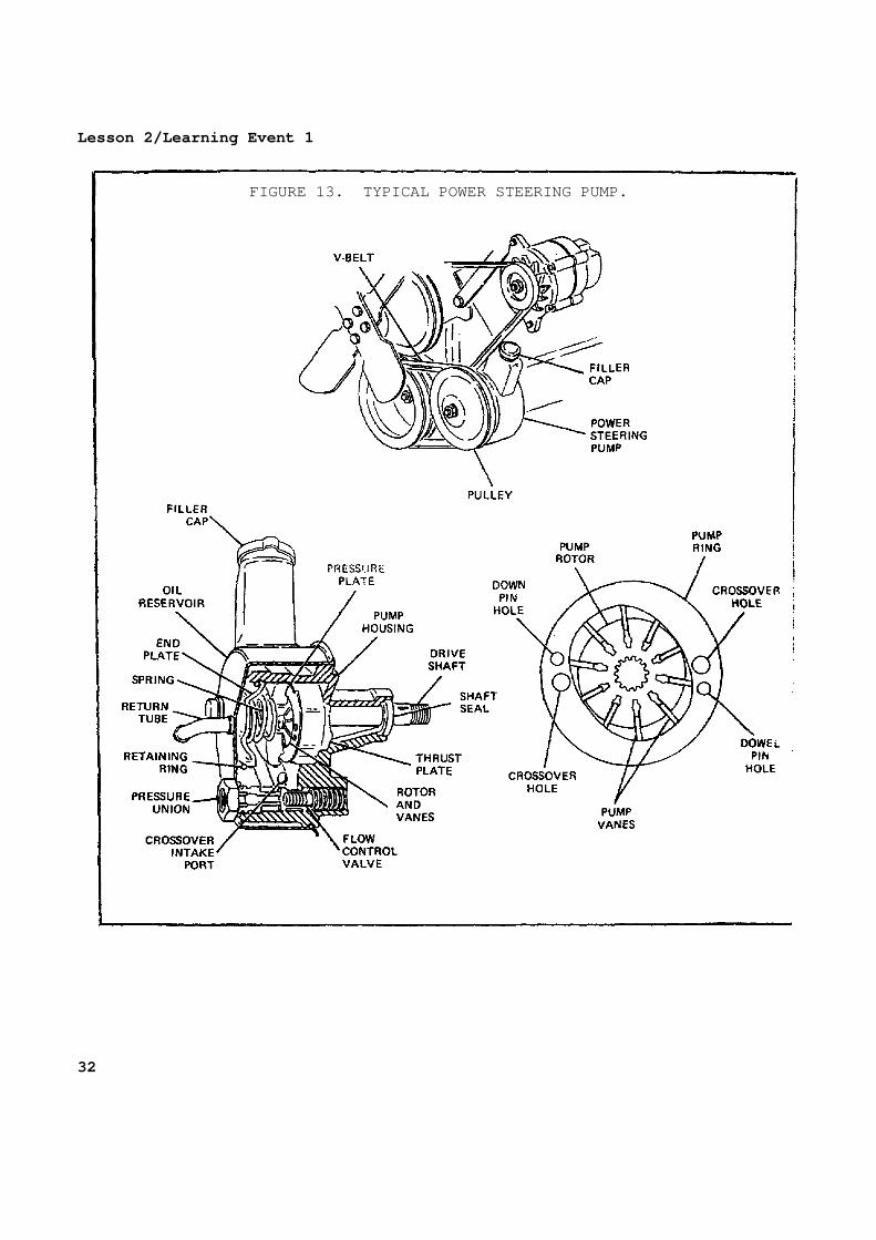
FIGURE 13. TYPICAL POWER STEERING PUMP.
32

Lesson 2/Learning Event 1 Pump All power steering systems contain a pump that supp lies hydraulic fluid under pressure to the other components in the syste m. The pump, which may be of the gear teeth, rotor, or vane type, usually is driven by the engine by a V-belt and is functional whenever the engine i s operating. On some models, the pump is mounted in front of the engine and is driven directly by the crankshaft. Pressure and flow relief valves ar e always built into the pump. These valves limit the amount of pressure an d flow the pump develops throughout different engine speeds. Reservoir The pump receives its oil supply from the reservoir , which usually is an integral part of the pump. Power steering fluid is added and checked at the reservoir. The fluid level should be kept at 3/4 full all the time. If the reservoir is full , there is no room for thermal expansion. If the f luid level is low , condensation may form.
33

Lesson 2/Learning Event 1
FIGURE 14. CONTROL VALVE.
Control valve The control valve is actuated by the steering wheel movements and directs the hydraulic fluid under pressure to the proper lo cation in the steering system. The control valve may be mounted either in the steering box or on the steering linkage, depending on system configura tion. 34
Lesson 2/Learning Event 1
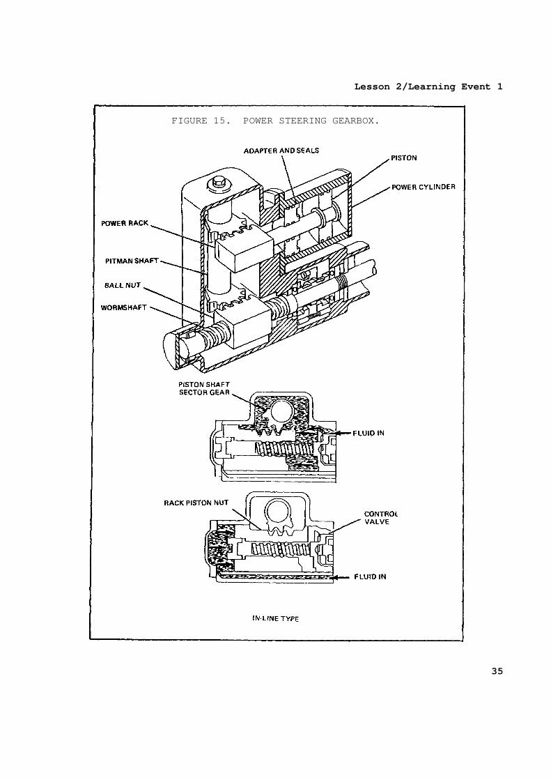
FIGURE 15. POWER STEERING GEARBOX.
35

Lesson 2/Learning Event 1 Gearbox The gearbox in an integral power steering system is basically a manual gearbox adapted to include a power assist package. Integral power steering gearboxes are of two types: offset and in-line. The offset type has a recirculating-ball gearbox with a rack meshe d to the pitman sector gear above or on the opposite side of the ball nut. The power steering force is developed in the power piston, wh ich is offset from the worm and nut and attached to the rack. The in-line design uses the recirculating ball-nut assembly as a powe r piston. In this design, the ball nut is sealed ins ide a cylindrical portion of the steering gear housing. The power steering e ffect is produced by alternately pressurizing either side of the power p iston. Hydraulic cylinder The hydraulic cylinder used on the semi-integral an d integral power steering systems is located on the steering linkage. The po wer assist is developed in the cylinder through the action of the pressuriz ed hydraulic fluid. The cylinder may have single- or double-wall constr uction. The hydraulic hoses connect to the ports on each end of the singl e-wall cylinder. The double-wall cylinder has connections on one end for both hoses and an internal passageway between the walls to pressurize the other end of the cylinder. Some linkage cylinders have shuttle valv es built into the piston. This valve opens at the end of the piston stroke. This feature helps eliminate full hydraulic pressure from acting on th e cylinder when the piston is bottomed by opening and allowing fluid to flow through the piston. 36
Lesson 2/Learning Event 1 OPERATION Neutral In the neutral position, there is no force required of the power steering system to turn the wheels; therefore, the fluid und er pressure must be bypassed through the system. This usually is accom plished in the control valve. When there is no steering force required by the driver, the spool in the control valve is centered by springs or hydraul ic pressure or both. This allows the oil to flow through the valve and b ack to the reservoir and allows the steering system to maintain position. Left and right turns As the driver starts to turn the steering wheel to make a left or right turn, the power steering system is activated. The spool is moved off center position and forced to the left or right end of the control valve. This opens the proper passageways for the pressurized oi l. The return port is also opened, and the fluid being displaced by the p iston in the cylinder returns to the reservoir. CONFIGURATIONS Linkage type In the linkage configuration, the control valve and power cylinder may be separate parts mounted on different parts of the li nkage. Integral The integral system incorporates the control valve and power assist into the steering gear as a unit. Semi-integral The control valve on the semi-integral system is mo unted to the steering gear, and a separate hydraulic cylinder is mounted to the linkage.
37

Lesson 2/Learning Event 2 Learning Event 2: DESCRIBE THE INSPECTION AND TROUBLESHOOTING PROCEDURES FOR POWER STEERING SYSTEMS TROUBLESHOOTING Hydraulic pumps, cylinders, motors, and valves are precision units. Smooth operation depends on frequent inspections and prope r servicing of hydraulic systems. They must be kept clean, and the oil and filters must be changed as recommended in the technical manuals. Improper operation can generally be traced to one o f the following causes: - Liquid of the wrong kind or of the wrong viscosi ty. - Not enough liquid in the system. - Air in the hydraulic units or lines. - Damaged or worn parts. - Oil leaks, internal or external. - Dirt, water, sludge, rust, metal cuttings, or ot her foreign matter
in the system. - Units and control linkage improperly adjusted. - Operator error. Troubleshooters should use procedures that will lea d them directly to the cause of troubles. Eliminate as much guesswork as possible. One set of procedures is called STOP, described as follows: S - Study the hydraulic circuit diagrams. Know what each part in the
system is supposed to do. This is probably the mos t vital part of troubleshooting.
T - Test, using all equipment and means available. Y ou must know
exactly what conditions exist in the system and how it reacts before you can make accurate decisions.
O - Organize the knowledge gained from the circuit-d iagram study and
hydraulic system tests; then determine the cause of the trouble. P - Perform repairs, taking time to do the job well. 38
Lesson 2/Learning Event 2 The troubleshooting section in vehicle TMs contains a list of troubles (malfunctions) of the vehicle's hydraulic systems, the probable causes of the troubles, and the corrective repairs that shoul d be made. Always use this list to aid you in troubleshooting the vehicle . INSPECTION Begin the inspection by checking the level and cond ition of the steering oil and looking for evidence of leaks. Inspect the hydraulic pump. Look especially for si gns of leaks at the pump mounting gasket and between the pump and its cover. Tighten the mounting and cover bolts if necessary. Examine all hydraulic hoses carefully, especially t he high-pressure hoses between the pump and the control valve and between the control valve and power cylinder. The hoses should be secure in thei r clamps and not rubbing against other parts or components. Unless there is evidence of leaks, do not tighten any of the hose fittings. Check the control valve for evidence of leaks and f or loose valve-to-steering jacket mounting bolts. If no leaks are evident in the system, you can now add oil to the reservoir if the oil level was low when you checked it. Of c ourse, if you find the oil dirty or mixed with water, drain the old oil an d refill it with clean oil. While the oil is draining, clean the filter s creen. Keep the oil level in the reservoir at 3/4 full to allow for exp ansion. Continue your inspection by checking the steering g ear itself. Look for evidence of lubrication oil leaks around t he gear housing gaskets and seals. Check the level of the lubrication oil in the steer ing gear housing by removing the filler plug in the top of the housing. If necessary, fill the housing with the proper grade of gear oil (GO). GO is much heavier than the OE used in the hydraulic system. This makes it eas y to decide whether the hydraulic system or the steering gear is at fault i f there is a leak around the steering gear housing. Check the steering gear-to-frame bracket mounting b olts with a wrench. Also check the steering column-to-dash panel bracket bol ts for tightness.
39

Lesson 2/Learning Event 2 Start the engine, and check the hydraulic system fo r leaks while oil pressure is applied. Remember that high pressure i s developed in the system only when a turning effort is applied on the steeri ng wheel. So, have a buddy turn the steering wheel while you look for sl ight oil leaks. Don't hold the steering against the steering stop for mor e than a few seconds at a time because this can damage the hydraulic system. The relief valve will open to prevent the pressure from going high enough to rupture lines and units; however, the high pressure creates heat whic h can damage the system. Road-test the vehicle. Check for any tendency to w ander, weave back and forth, or shimmy. Check for excessive free play, b inding, and for pulling to the right or left. Check the action of the stee ring assist through both right and left turns. The steering effort required should be so small that you can turn the steering wheel with your thumb and forefinger while the vehicle is moving. ISOLATING FAULTS If the road test reveals any steering faults, the n ext step is to find the cause. (Faults that are peculiar to the power stee ring system of the 5-ton truck will be described.) If the steering was hard or was binding on turns, t he trouble could be the power steering gear, steering column jacket linkage , or steering knuckle pivots. To pinpoint the trouble, you will need to disconnect the steering linkage from the steering gear at the point where t he upper drag link connects to the pitman arm. - To disconnect the drag link from the pitman arm, remove the cotter
pin and dust shield from the upper drag link end. Unscrew the drag link adjusting plug as far as possible without remo ving it. Turn the steering wheel back and forth to loosen the bal l seats on the pitman arm ball stud. Then, lift the drag link fro m the pitman arm ball stud.
- Use a jack and raise the front axle until both f ront wheels are off
the ground. Grasp one front wheel at the front and rear, and pivot the wheels back and forth on their steering knuckle s. If the wheels pivot easily, the binding is not caused by the stee ring knuckles or steering linkage.
40

Lesson 2/Learning Event 2 The binding may be caused by the steering column ja cket being misaligned with the steering gear. - To check for this, loosen the mounting bracket c apscrews and the
clamp bolt securing the steering column jacket to t he instrument panel. If the column is misaligned enough to cause the steering shaft to bind, it will realign itself when the caps crews and clamp are loosened. Tighten the mounting screws and clam p; then turn the steering wheel to check for binding. If it still b inds, the trouble is in the steering gear.
- If the problem was hard steering with no binding , the cause is in
the hydraulic system. If the vehicle pulled to the right or left during t he road test, this fault could be caused by unequal tire pressure or draggin g brakes. On the 5-ton truck, however, pulling to one side can also be cau sed by the hydraulic power steering. You check for this in the followin g manner: - The drag link must be disconnected from the pitm an arm. Make sure
that the steering gear is in the midposition. Do t his by turning the steering wheel in one direction as far as it wi ll go. Then, counting the number of turns, turn the wheel in the opposite direction as far as it will go. Turn the wheel bac k half the number of turns you counted from stop to stop.
- Now, start the engine and operate it at fast idl e. Without touching
the steering wheel, watch it to see if it moves by itself. If it does, the power steering control valve is not cente red, and it does not return to the neutral position. This can be ca used by loose control valve mounting bolts or loose cam cover bol ts at the ends of the cam. If tightening these bolts does not correc t the problem, the cause is a defective control valve or the valve is not adjusted properly.
- After the cause of trouble has been corrected, y ou must reconnect
the drag link to the pitman arm. When connecting t he drag link, make sure that the ball stud is properly positioned between the ball seats and tighten the drag link adjusting plug unti l it bottoms. Then back off the adjusting plug until its slot is aligned with the first cotter pin hole. Install the dust shield and a new cotter pin; then, lubricate the drag link.
41

Lesson 2/Learning Event 2 - If the repairs are beyond the unit level of main tenance, notify your
maintenance sergeant so that he can arrange for the truck to be repaired by the support unit.
To isolate the fault in the hydraulic system, the r epairer from the support unit will probably use a pressure test gage set tha t is designed for this task. In case you get to assist on the job, here i s how it is done. The high-pressure line between the pump and control valve is disconnected at the control valve. A tee fitting is installed on t he control valve where the line was removed. Then, the high-pressure line is connected to the tee fitting. At the center of the tee, connect the pre ssure gage using a short hose provided in the test kit. The hydraulic syste m can now be operated, and the pressures developed will be shown on the pr essure gage. Before making any pressure tests, fill the reservoi r to the proper level with OE 10 and operate the engine until the hydraul ic oil is at normal operating temperature. If a rapid pressure buildup occurs when the engine is started, turn the engine off quickly. Look for plugged lines, fittings, and oil passages before going any farther. A plugg ed or partially plugged passage can cause pressure buildup that will burst lines and castings. After the unit has reached normal operating tempera ture, turn the steering wheel for a right turn with the engine running at 1 ,000 RPM. Continue turning the steering wheel until the right turn sto p is reached; then, hold it tight against the stop for just a few seconds. The gage should read 750 PSI for trucks with gasoline engines and between 85 0 and 1,000 PSI for multifuel and diesel engines. To repeat this test in the left turn position, it m ay be necessary to have an assistant hold a piece of iron, 1/4-inch thick, before the front axle left turn stop. If the hydraulic power piston is a llowed to travel to the end of the cylinder on a left turn, it uncovers a p ort that allows the pressure to escape. The 1/4-inch piece of iron pre vents the piston from traveling far enough to uncover the port. 42

Lesson 2/Learning Event 2 If the pressure is too low, another test is necessa ry to tell which unit is at fault, if the relief valve and pump are separate assemblies. This is done by blocking the oil flow to the relief valve. Don't let the pressure build above 750 PSI when you make the pressure test with the relief valve blocked. If this test raises the pressure, the rel ief valve is defective. If the pressure is still too low, the pump is proba bly defective. If replacing the pump does not raise the pressure, the trouble is internal leakage in the control valve or power cylinder. If the pressure was too high with the relief valve connected properly in the system, the relief valve is at fault. On trucks wi th gasoline engines, the relief valve is replaced separately, but the entire pump must be replaced on trucks with multifuel and Mack diesel engines.
43

Lesson 2 PRACTICE EXERCISE 1. The power steering system that incorporates the control valve, power
assist, and steering gear into a single unit is the a. linkage type. b. integral. c. semi-integral. 2. The power steering system is activated by the a. steering wheel. b. hydraulic pump. c. control valve. 3. Hydraulic pumps are precision units. Therefore, it is necessary to
regularly change the a. filter(s). b. drive belts. c. relief valves. 4. Condensation is most likely to form in a hydraul ic reservoir when the
liquid a. level is low. b. level is high. c. is too hot. 5. What equipment is required to isolate faults in the power steering
hydraulic system? a. Hydraulic stand b. External oil pressure c. Pressure test gage 44

Lesson 2
This page intentionally left blank.
45

Lesson 2 ANSWERS TO PRACTICE EXERCISE 1. b (page 37) 2. a (page 37) 3. a (page 38) 4. a (page 33) 5. c (page 42) 46