Wheeled Robotic Mobility
54
Wheeled Robotic Mobility Dimi Apostolopoulos
Transcript of Wheeled Robotic Mobility
Wheeled Robotic Mobility
Dimi Apostolopoulos
ROBOTIC MOBILITY – Dimi Apostolopoulos Page 2
Significance of Mobility
Move
Position
Transport
Employ instruments and tools
React to work loads
…in a controllable fashion
ROBOTIC MOBILITY – Dimi Apostolopoulos Page 3
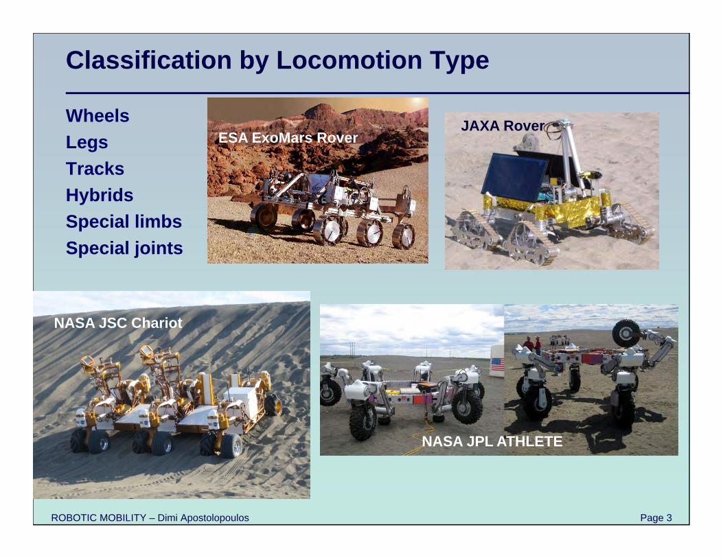
Classification by Locomotion Type
WheelsLegsTracksHybrids Special limbsSpecial joints
ESA ExoMars Rover
NASA JSC Chariot
NASA JPL ATHLETE
JAXA Rover
ROBOTIC MOBILITY – Dimi Apostolopoulos Page 4
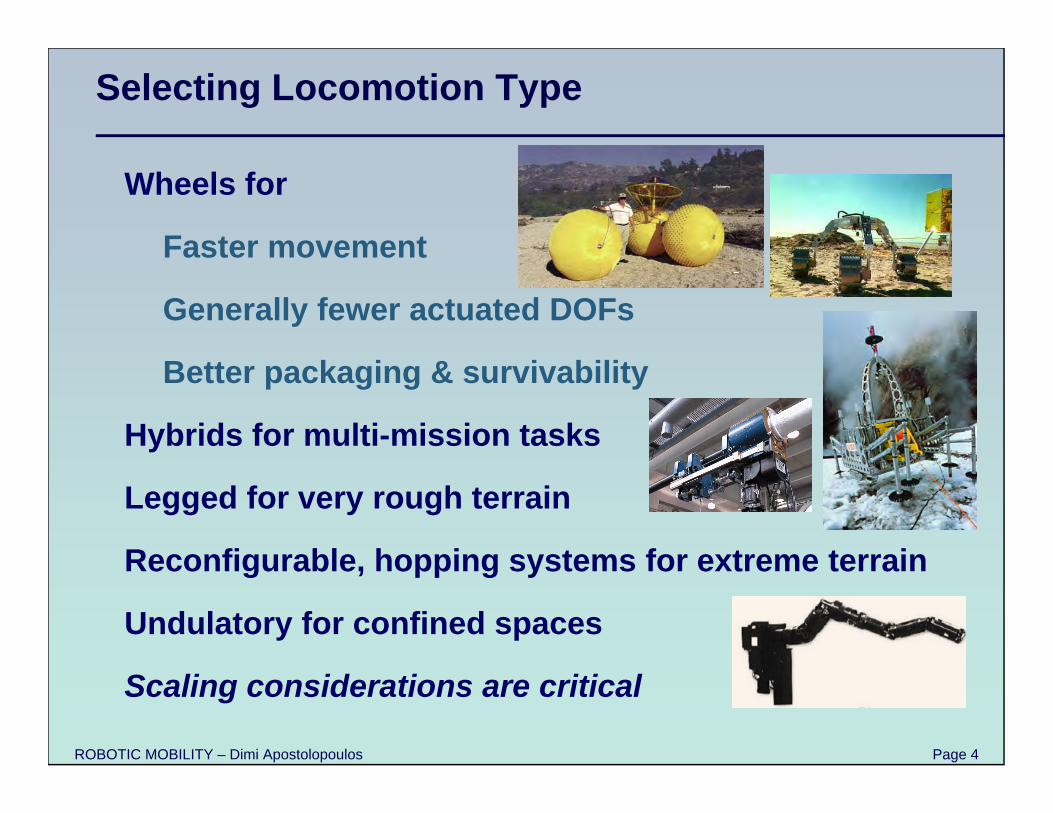
Selecting Locomotion Type
Wheels for
Faster movement
Generally fewer actuated DOFs
Better packaging & survivability
Hybrids for multi-mission tasks
Legged for very rough terrain
Reconfigurable, hopping systems for extreme terrain
Undulatory for confined spaces
Scaling considerations are critical
ROBOTIC MOBILITY – Dimi Apostolopoulos Page 5
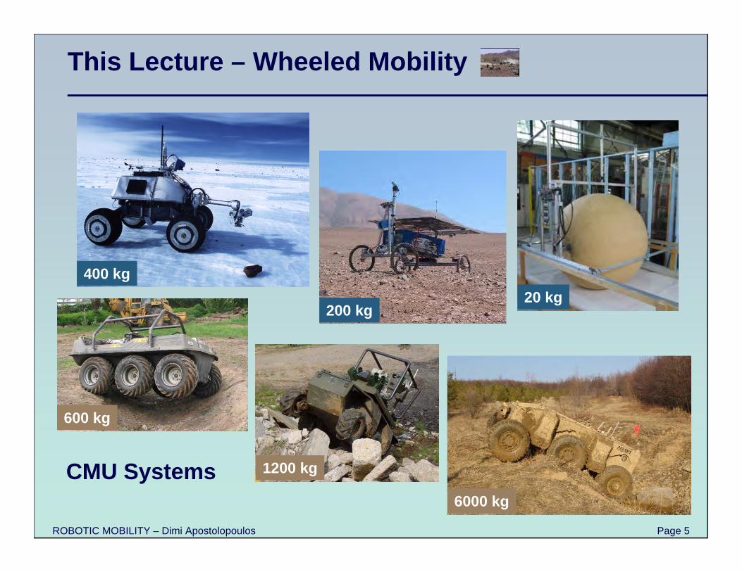
This Lecture – Wheeled Mobility
600 kg
1200 kg
6000 kg
400 kg20 kg
200 kg
CMU Systems
ROBOTIC MOBILITY – Dimi Apostolopoulos Page 6
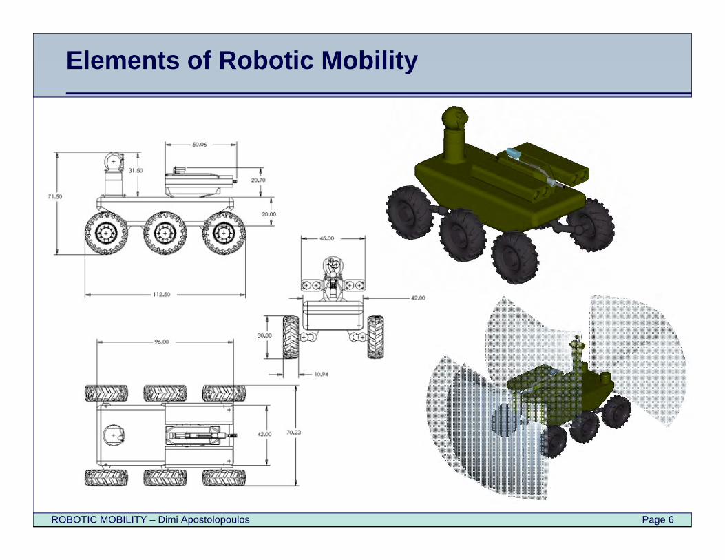
Elements of Robotic Mobility
ROBOTIC MOBILITY – Dimi Apostolopoulos Page 7
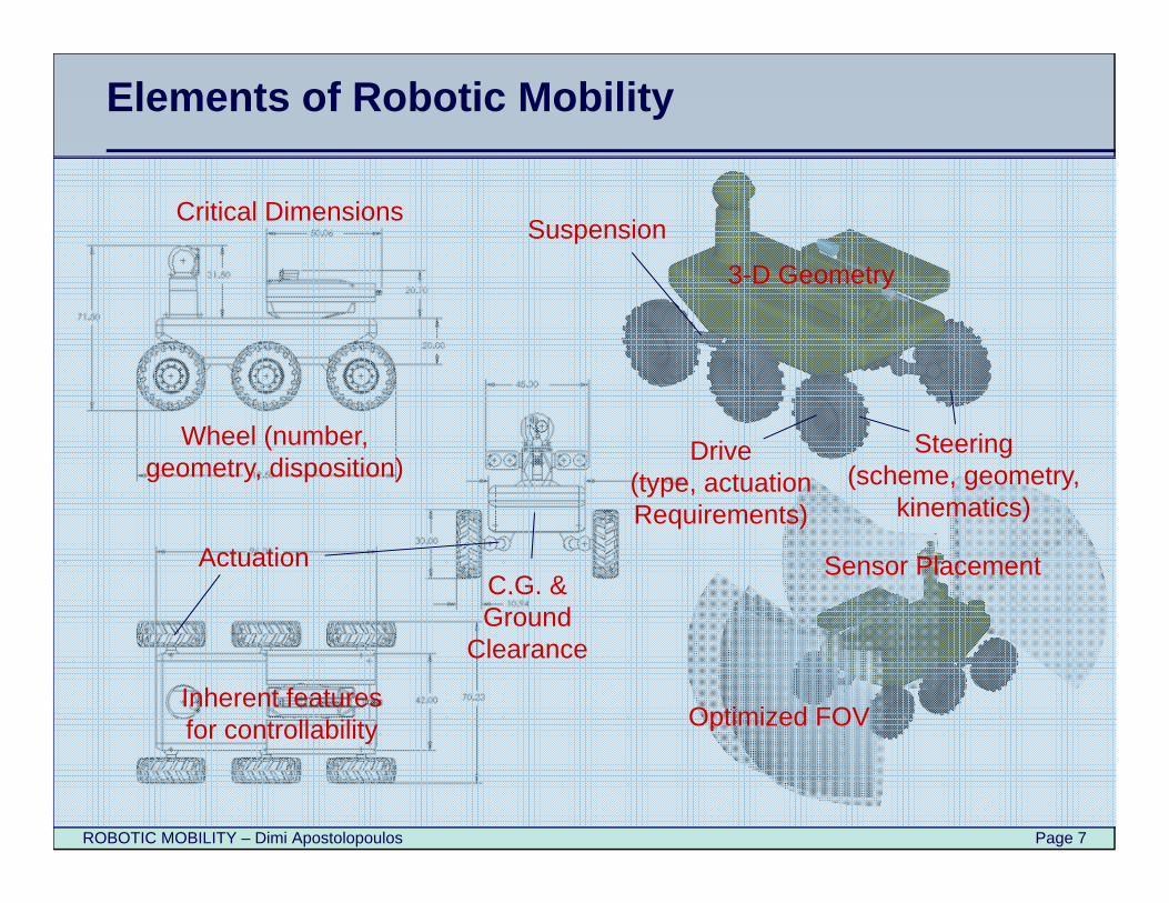
Elements of Robotic Mobility
3-D Geometry
Sensor Placement
Optimized FOV
Wheel (number, geometry, disposition) Drive
(type, actuationRequirements)
C.G. & Ground
Clearance
Critical Dimensions
Steering(scheme, geometry,
kinematics)
Suspension
Actuation
Inherent features for controllability
ROBOTIC MOBILITY – Dimi Apostolopoulos Page 8
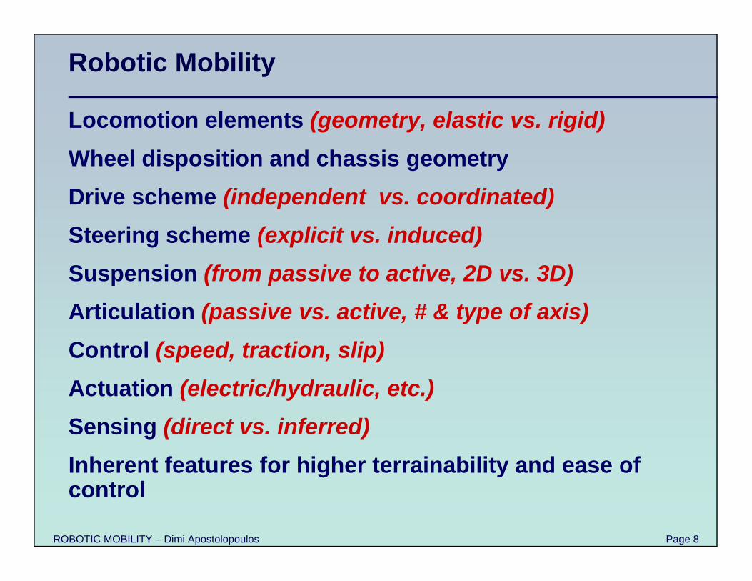
Robotic Mobility
Locomotion elements (geometry, elastic vs. rigid)Wheel disposition and chassis geometryDrive scheme (independent vs. coordinated)Steering scheme (explicit vs. induced)Suspension (from passive to active, 2D vs. 3D)Articulation (passive vs. active, # & type of axis)Control (speed, traction, slip)Actuation (electric/hydraulic, etc.)Sensing (direct vs. inferred)Inherent features for higher terrainability and ease of control
ROBOTIC MOBILITY – Dimi Apostolopoulos Page 9
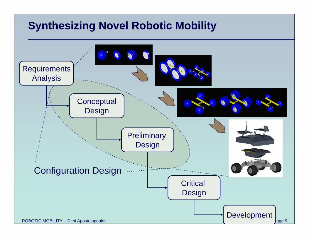
Synthesizing Novel Robotic Mobility
RequirementsAnalysis
ConceptualDesign
Critical Design
Preliminary Design
Development
Configuration Design
ROBOTIC MOBILITY – Dimi Apostolopoulos Page 10
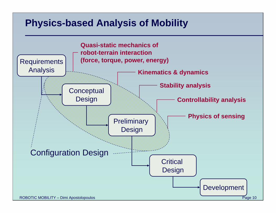
Physics-based Analysis of Mobility
RequirementsAnalysis
ConceptualDesign
Critical Design
Preliminary Design
Development
Configuration Design
Quasi-static mechanics of robot-terrain interaction(force, torque, power, energy)
Kinematics & dynamics
Stability analysis
Controllability analysis
Physics of sensing
ROBOTIC MOBILITY – Dimi Apostolopoulos Page 11
In-soil Performance – Terramechanics
Wheel-soil interaction models
Wheel sinkage
Motion resistance and traction
Force, torque, power, energy
Sizing wheels, drive actuation, drive electronics, drive mechanisms
ROBOTIC MOBILITY – Dimi Apostolopoulos Page 12
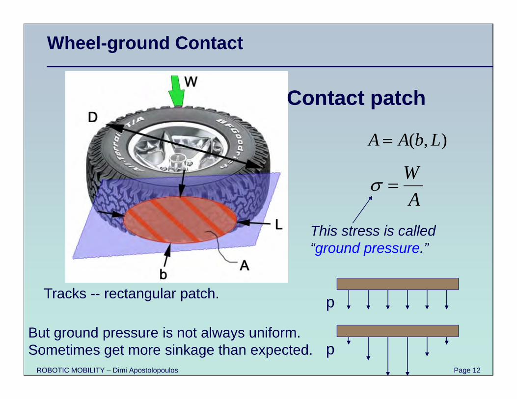
Contact patch
This stress is called “ground pressure.”
WA
( , )A A b L
But ground pressure is not always uniform.Sometimes get more sinkage than expected.
p
p
Tracks -- rectangular patch.
Wheel-ground Contact
ROBOTIC MOBILITY – Dimi Apostolopoulos Page 13
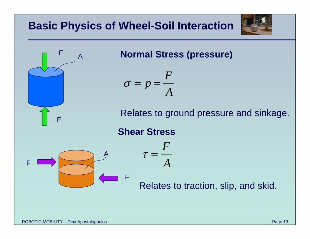
Basic Physics of Wheel-Soil Interaction
FpA
F
F
A Normal Stress (pressure)
Relates to traction, slip, and skid.
F
F
A
Shear StressFA
Relates to ground pressure and sinkage.
ROBOTIC MOBILITY – Dimi Apostolopoulos Page 14
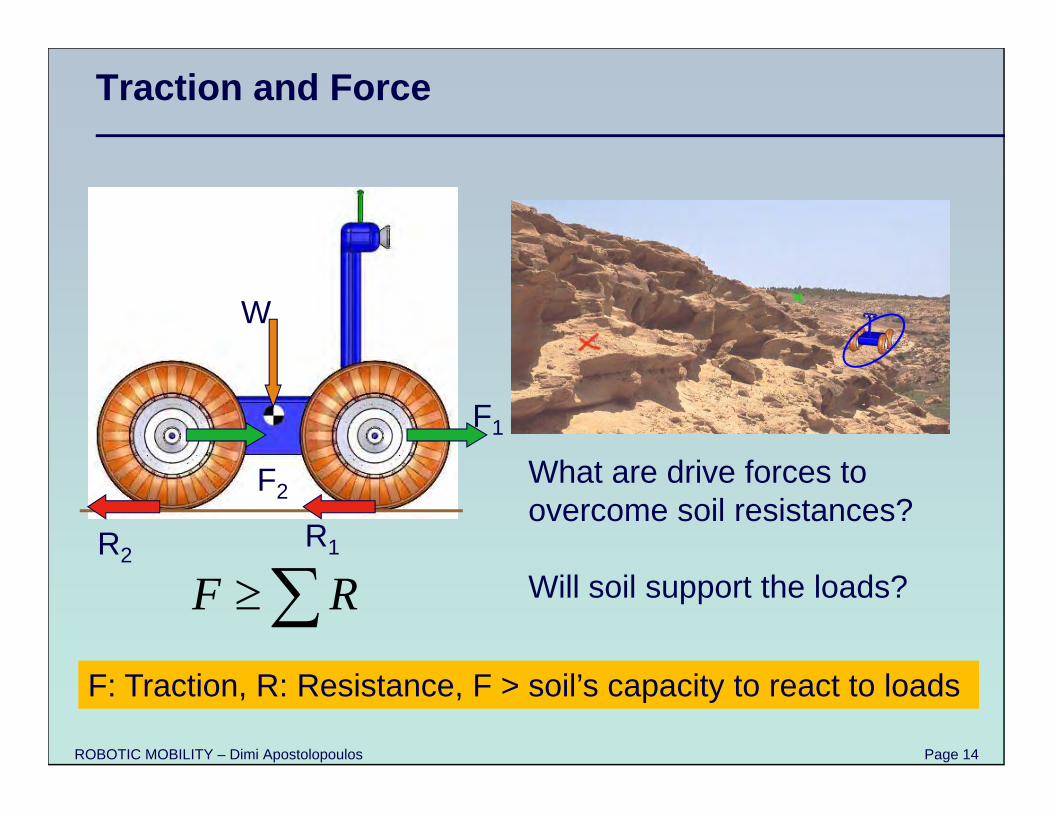
Traction and Force
What are drive forces to overcome soil resistances?
Will soil support the loads?
F1
F2
R1R2
F R
W
F: Traction, R: Resistance, F > soil’s capacity to react to loads
ROBOTIC MOBILITY – Dimi Apostolopoulos Page 15
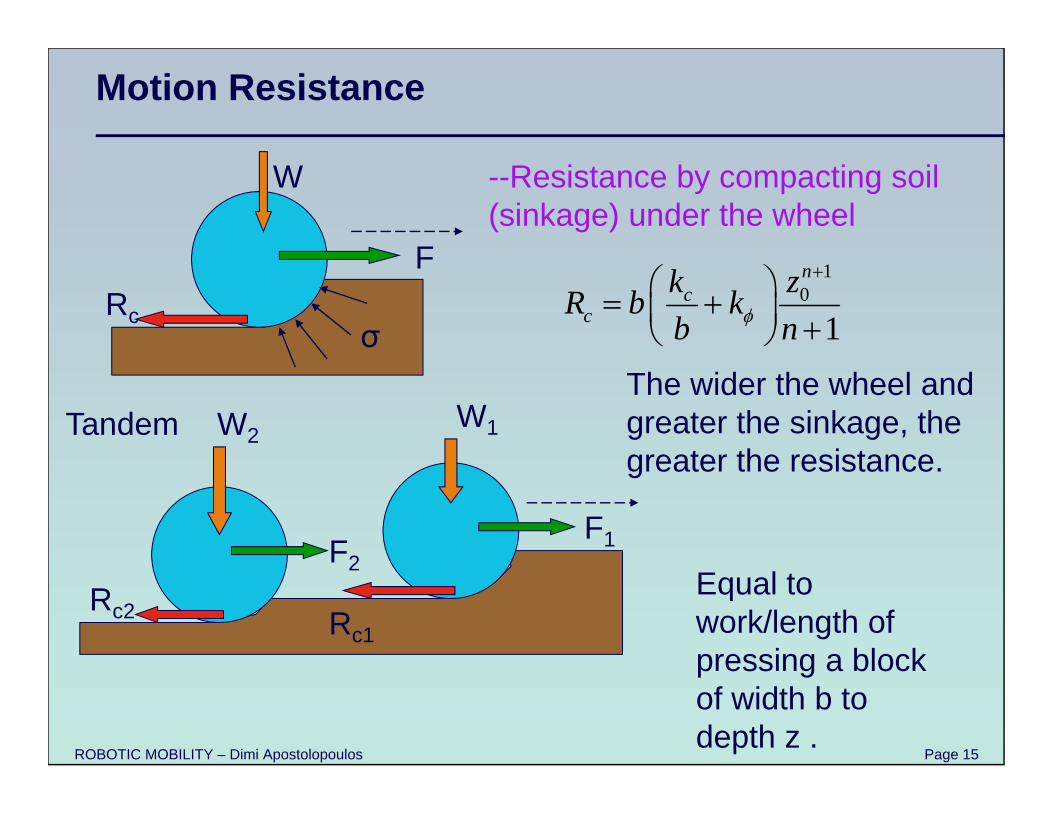
Motion Resistance
--Resistance by compacting soil (sinkage) under the wheel
Rc
W
F
σ
Tandem W1W2
F1F2
Rc2 Rc1
10
1
nc
ck zR b kb n
The wider the wheel and greater the sinkage, the greater the resistance.
Equal to work/length of pressing a block of width b to depth z .
ROBOTIC MOBILITY – Dimi Apostolopoulos Page 16
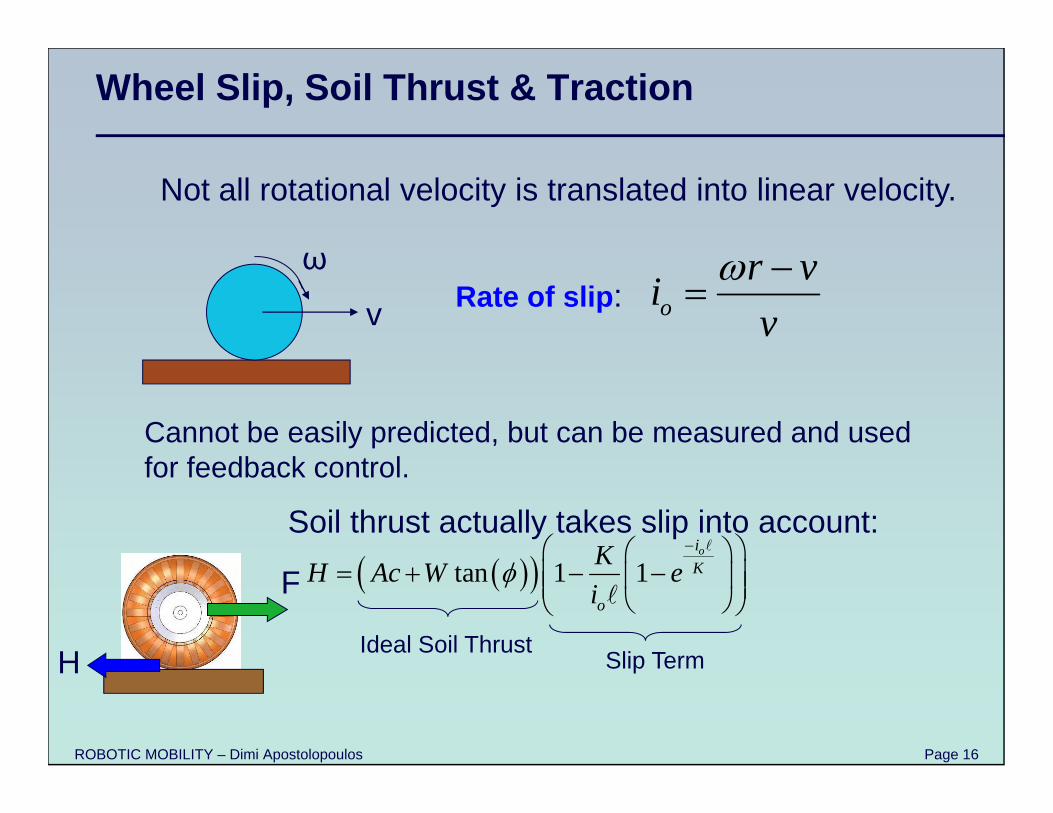
Wheel Slip, Soil Thrust & Traction
or viv
Cannot be easily predicted, but can be measured and used for feedback control.
v
ω
Not all rotational velocity is translated into linear velocity.
Rate of slip:
tan 1 1oi
K
o
KH Ac W ei
Soil thrust actually takes slip into account:
Ideal Soil ThrustSlip Term
F
H
ROBOTIC MOBILITY – Dimi Apostolopoulos Page 17
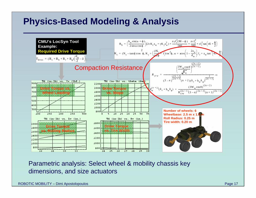
Physics-Based Modeling & Analysis
Rb
bw + sin
2 cossin--------------------------------- 2cKczw K zw
2+ l r
2 90 – 540
-------------------------------c lr
2
180----------- cl r
2 45 2---+
tan+ + +=
Kc N c tan– K 2N
tan----------- 1+ 2 1
2zw
dw---------–
l r zw 452---–
2tan=acos=cos=
2cos=
CMU’s LocSyn ToolExample:Required Drive Torque
Tdrws Rc Rb Rr+ + Rg+ dw
2------ – =
R cr w
3W w cos
dw
-------------------------
2 n 2+ 2 n 1+
------------------
3 n–
2 n 2+ 2 n 1+
----------------------n 1+ k c bw
k +
12n 1+
------------------------------------------------------------------------------------------------------------------------------ =
dwn 1+ k c bw
k + 3Ww cos
2n 2+
Rcrw2n 1+ 3 n– 2n 2+ n 1+ 2n 1+
------------------------------------------------------------------------------------------=
Number of wheels: 6Wheelbase: 2.5 m x 1.5 mRoll Radius: 0.25 mTire width: 0.20 m
Drive Torque vs. Wheel Loading
Drive Torquevs. Rolling Radius
Drive Torque vs. Slope
Drive Torque vs. Tire Width
Parametric analysis: Select wheel & mobility chassis key dimensions, and size actuators
Compaction Resistance
ROBOTIC MOBILITY – Dimi Apostolopoulos Page 18
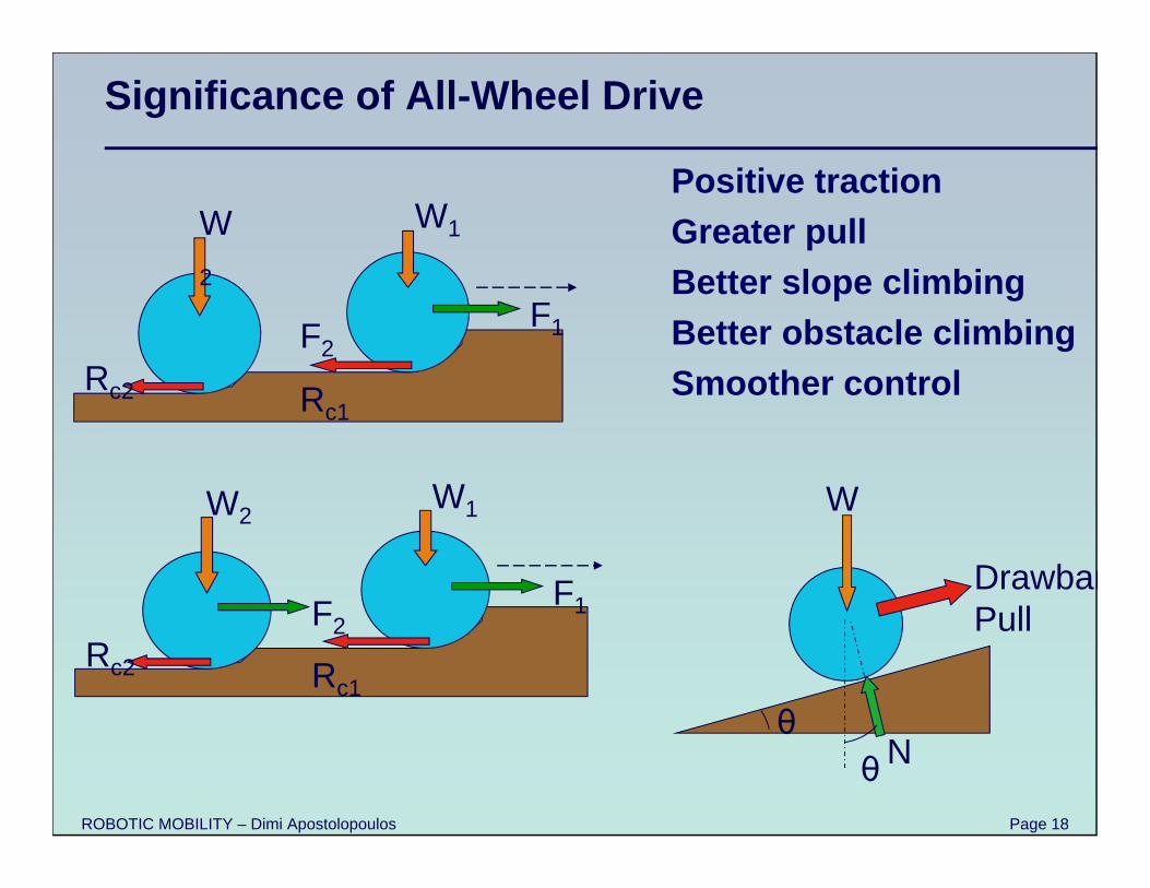
Significance of All-Wheel Drive
W1W2
F1F2Rc2 Rc1
W1W2
F1F2Rc2 Rc1
W
N
DrawbarPull
θθ
Positive tractionGreater pullBetter slope climbingBetter obstacle climbingSmoother control
ROBOTIC MOBILITY – Dimi Apostolopoulos Page 19
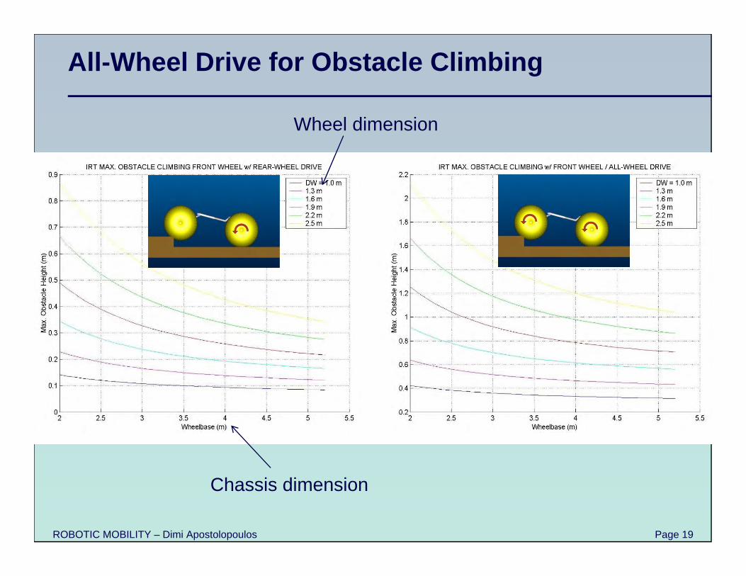
All-Wheel Drive for Obstacle Climbing
Wheel dimension
Chassis dimension
ROBOTIC MOBILITY – Dimi Apostolopoulos Page 20
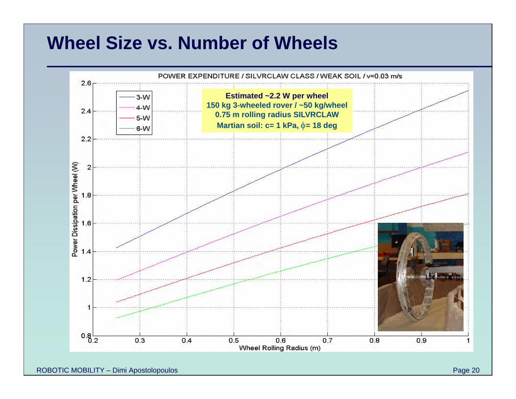
Wheel Size vs. Number of Wheels
Estimated ~2.2 W per wheel150 kg 3-wheeled rover / ~50 kg/wheel
0.75 m rolling radius SILVRCLAWMartian soil: c= 1 kPa, = 18 deg
ROBOTIC MOBILITY – Dimi Apostolopoulos Page 21
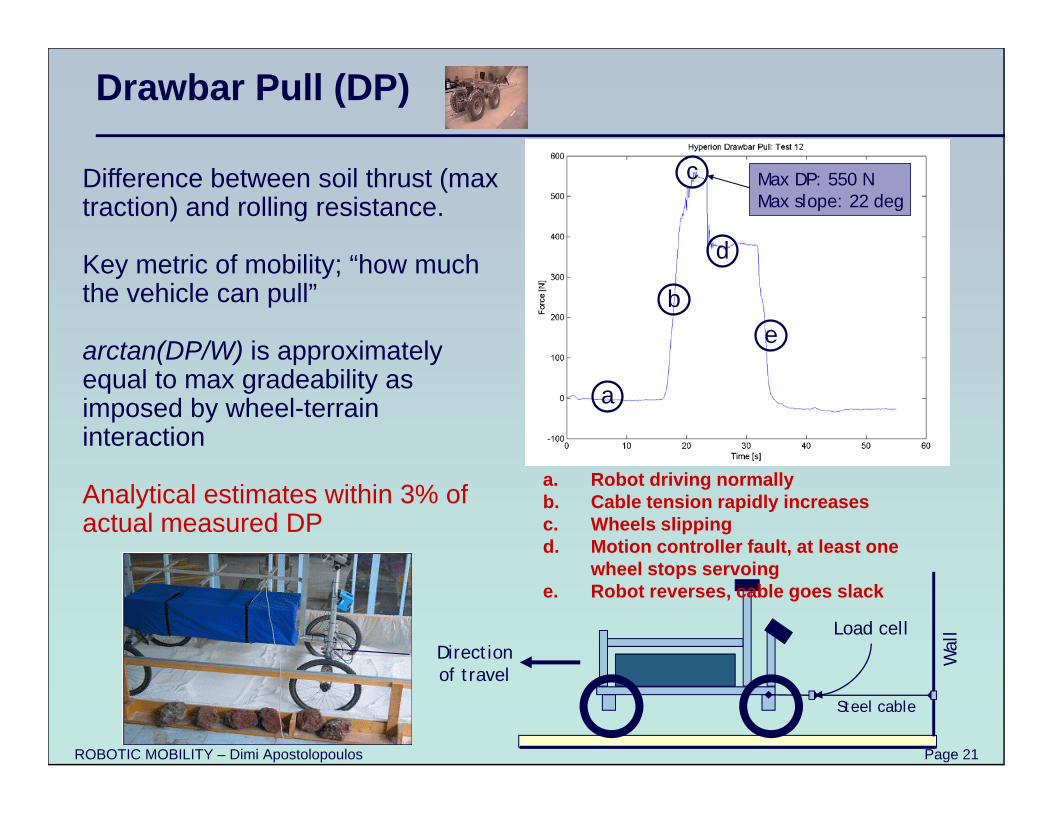
Drawbar Pull (DP)
Direction of travel
Steel cable
Load cell
Wal
l
a. Robot driving normallyb. Cable tension rapidly increasesc. Wheels slippingd. Motion controller fault, at least one
wheel stops servoinge. Robot reverses, cable goes slack
c
a
b
d
e
Max DP: 550 NMax slope: 22 deg
c
a
b
d
e
Max DP: 550 NMax slope: 22 deg
Difference between soil thrust (max traction) and rolling resistance.
Key metric of mobility; “how much the vehicle can pull”
arctan(DP/W) is approximately equal to max gradeability as imposed by wheel-terrain interaction
Analytical estimates within 3% of actual measured DP
ROBOTIC MOBILITY – Dimi Apostolopoulos Page 22
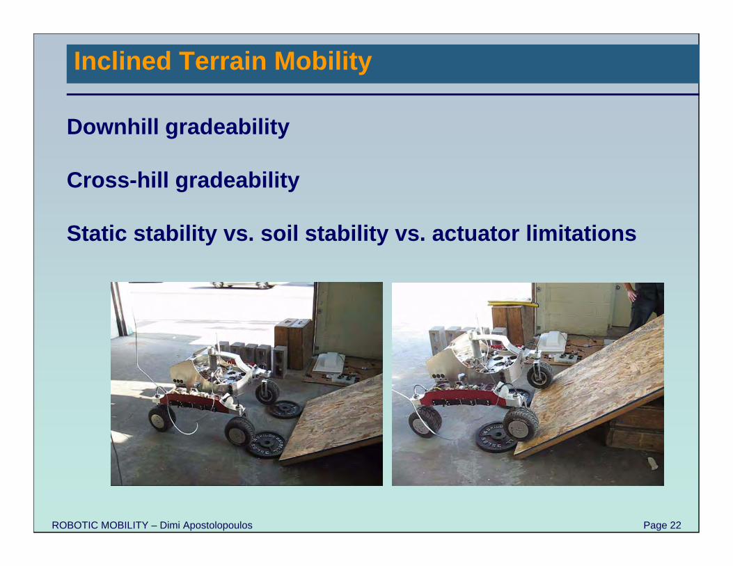
Inclined Terrain Mobility
Downhill gradeability
Cross-hill gradeability
Static stability vs. soil stability vs. actuator limitations
ROBOTIC MOBILITY – Dimi Apostolopoulos Page 23
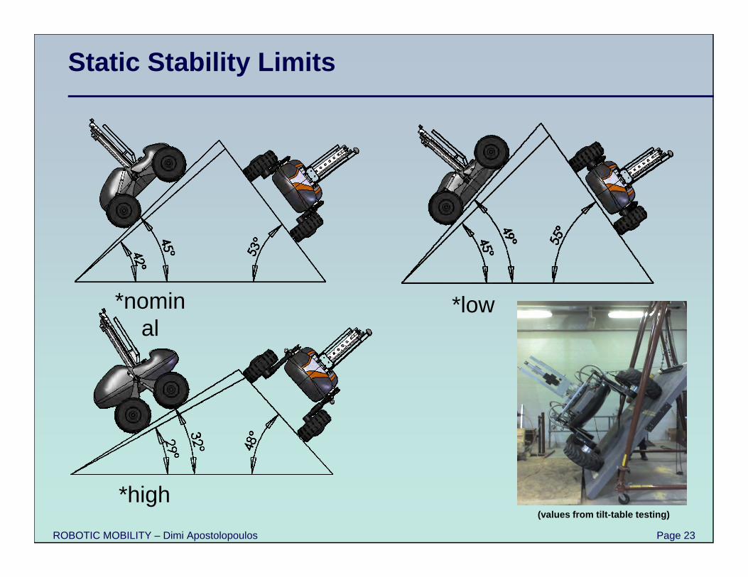
Static Stability Limits
*low*nominal
*high(values from tilt-table testing)
ROBOTIC MOBILITY – Dimi Apostolopoulos Page 24
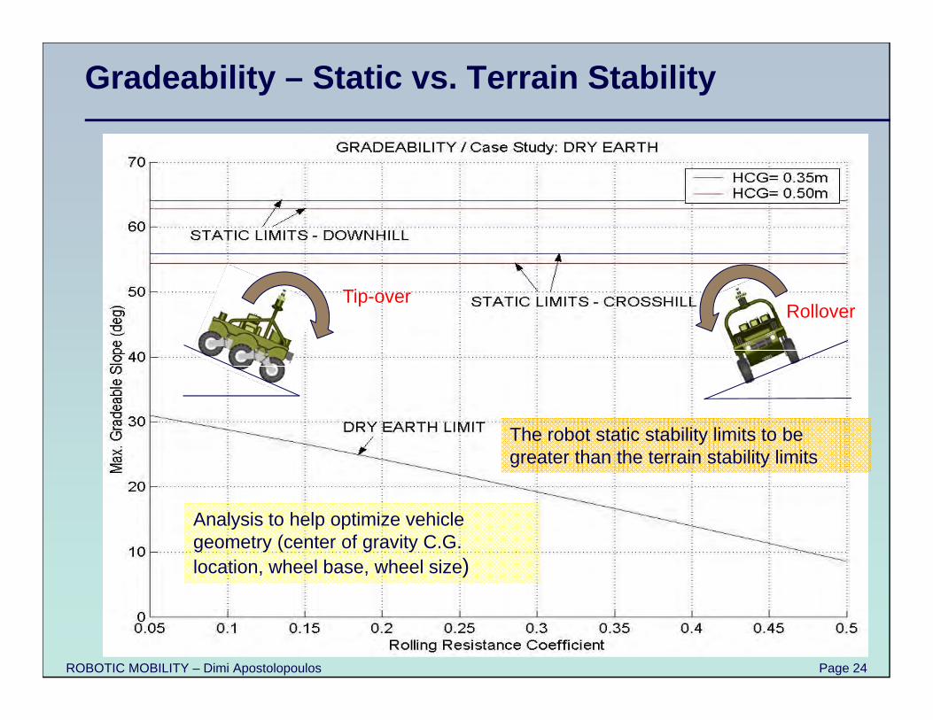
Gradeability – Static vs. Terrain Stability
Analysis to help optimize vehicle geometry (center of gravity C.G. location, wheel base, wheel size)
The robot static stability limits to be greater than the terrain stability limits
Tip-overRollover
ROBOTIC MOBILITY – Dimi Apostolopoulos Page 25
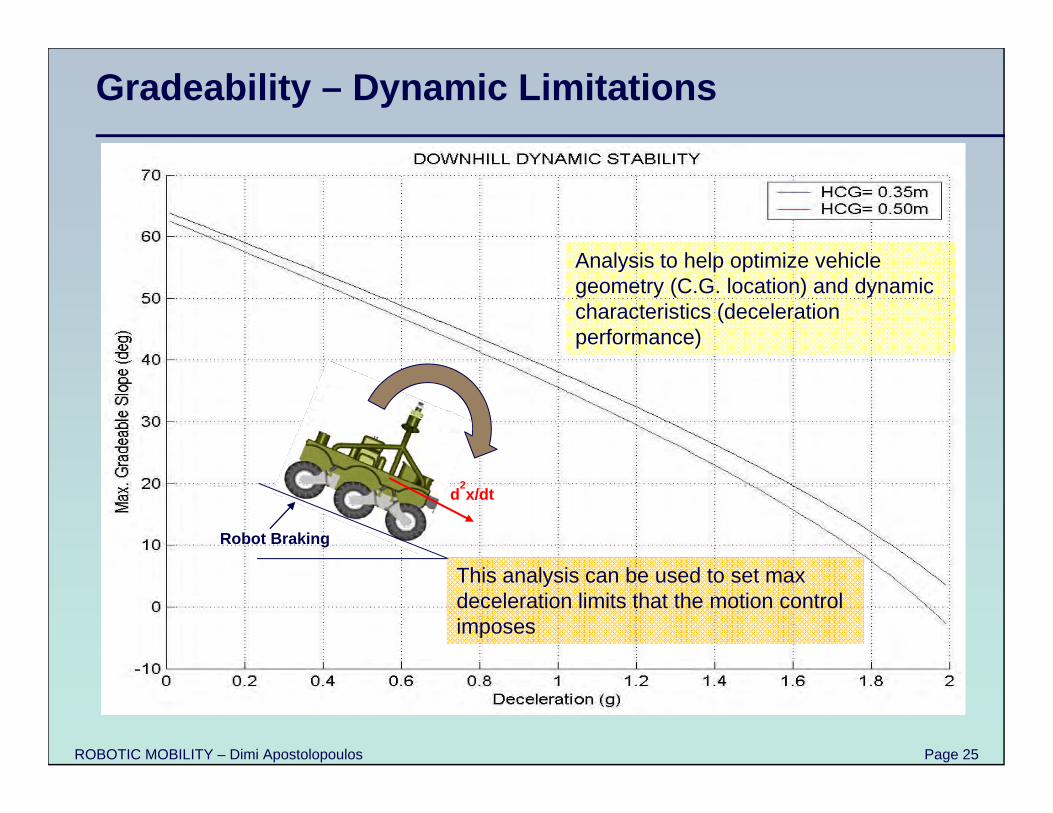
Gradeability – Dynamic Limitations
Robot Braking
d2x/dt
Analysis to help optimize vehicle geometry (C.G. location) and dynamic characteristics (deceleration performance)
This analysis can be used to set max deceleration limits that the motion control imposes
ROBOTIC MOBILITY – Dimi Apostolopoulos Page 26
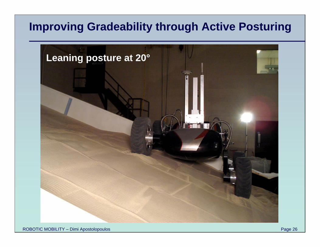
Improving Gradeability through Active Posturing
Leaning posture at 20°
ROBOTIC MOBILITY – Dimi Apostolopoulos Page 27
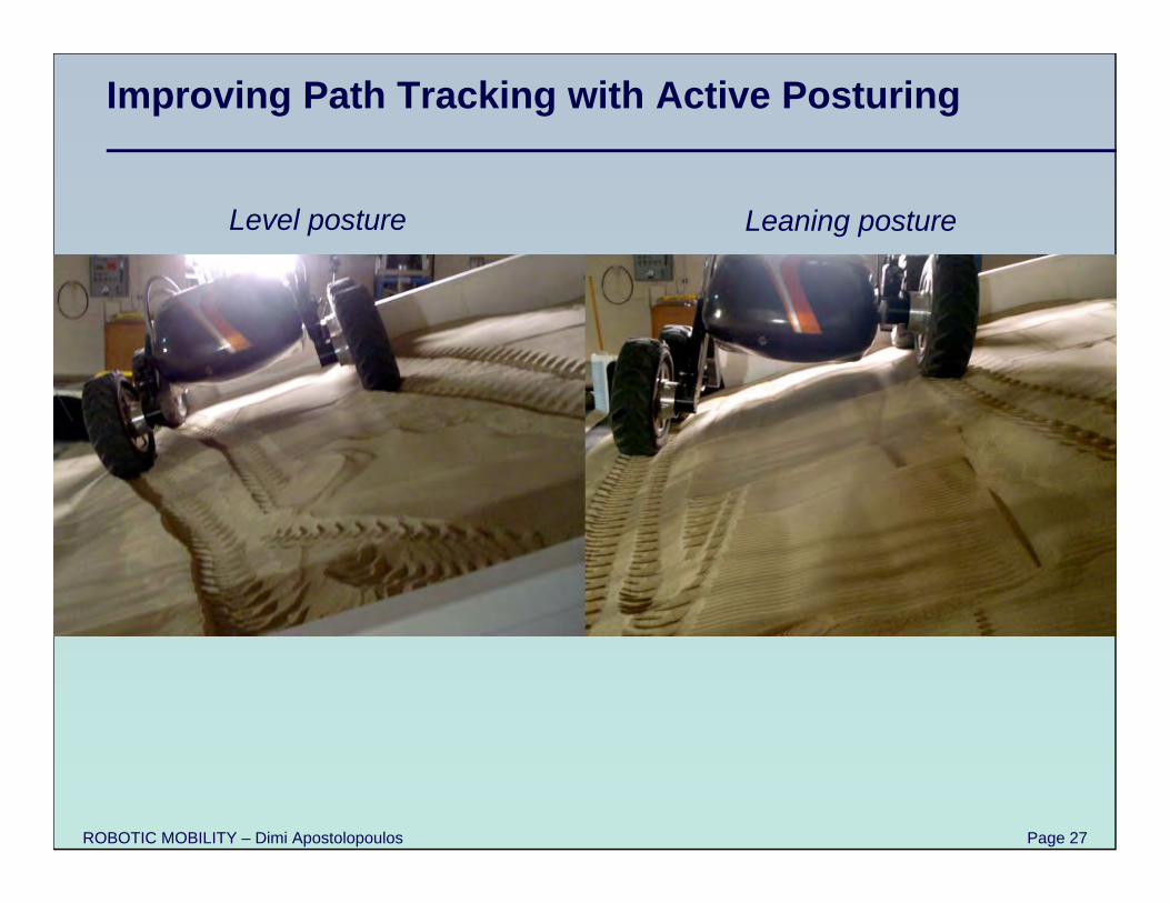
Improving Path Tracking with Active Posturing
Level posture Leaning posture
ROBOTIC MOBILITY – Dimi Apostolopoulos Page 28
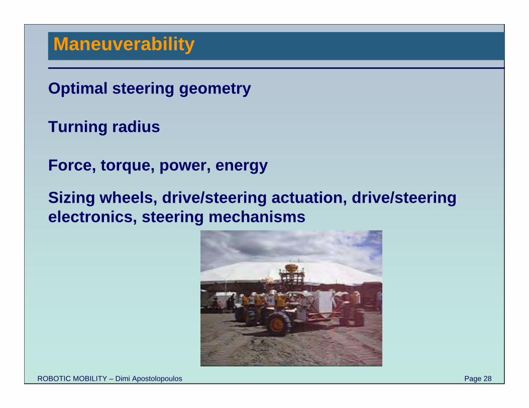
Maneuverability
Optimal steering geometry
Turning radius
Force, torque, power, energy
Sizing wheels, drive/steering actuation, drive/steering electronics, steering mechanisms
ROBOTIC MOBILITY – Dimi Apostolopoulos Page 29
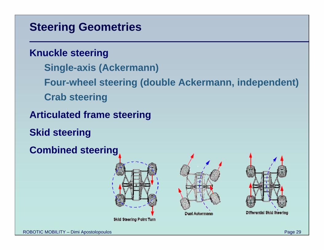
Steering Geometries
Knuckle steeringSingle-axis (Ackermann)Four-wheel steering (double Ackermann, independent)Crab steering
Articulated frame steering
Skid steering
Combined steering
ROBOTIC MOBILITY – Dimi Apostolopoulos Page 30
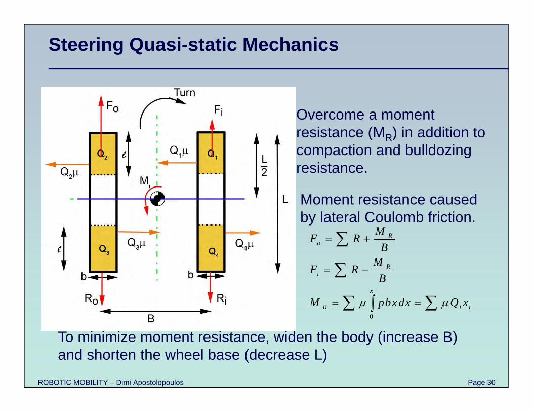
Steering Quasi-static Mechanics
Overcome a moment resistance (MR) in addition to compaction and bulldozing resistance.
Moment resistance caused by lateral Coulomb friction.
To minimize moment resistance, widen the body (increase B) and shorten the wheel base (decrease L)
0
Ro
Ri
x
R i i
MF RB
MF RB
M pbxdx Q x
ROBOTIC MOBILITY – Dimi Apostolopoulos Page 31
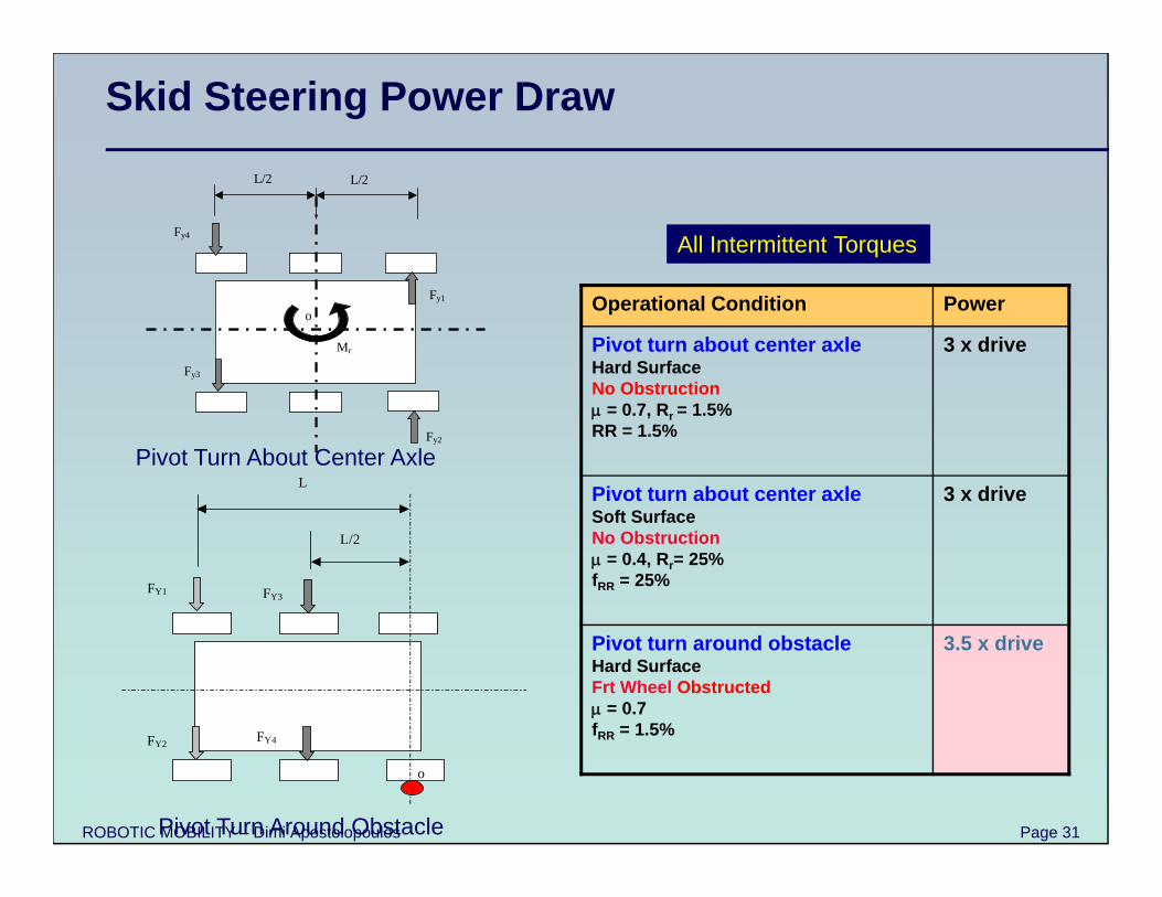
Skid Steering Power Draw
Operational Condition Power
Pivot turn about center axleHard SurfaceNo Obstruction = 0.7, Rr = 1.5%RR = 1.5%
3 x drive
Pivot turn about center axleSoft SurfaceNo Obstruction = 0.4, Rr= 25%fRR = 25%
3 x drive
Pivot turn around obstacleHard SurfaceFrt Wheel Obstructed = 0.7fRR = 1.5%
3.5 x drive
FY2
FY1 FY3
FY4
o
L
L/2
Pivot Turn Around Obstacle
Mr
o Fy1
Fy4
Fy3
Fy2
L/2 L/2
Pivot Turn About Center Axle
All Intermittent Torques
ROBOTIC MOBILITY – Dimi Apostolopoulos Page 32
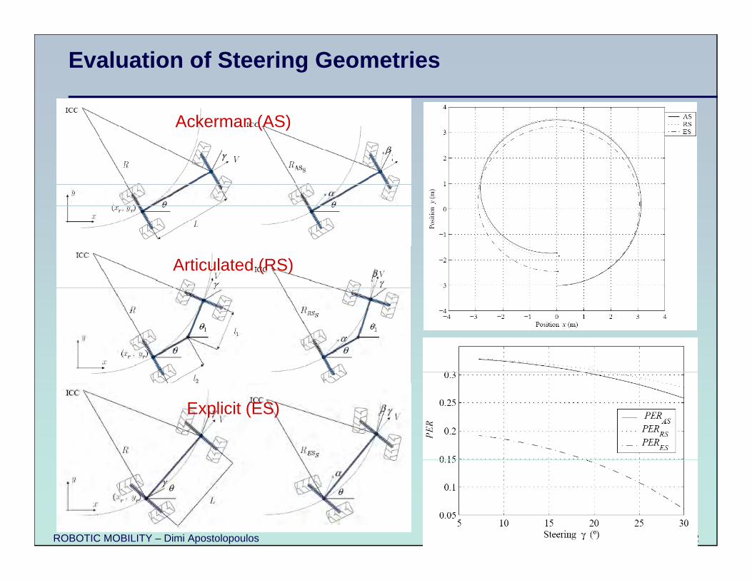
Evaluation of Steering Geometries
Ackerman (AS)
Articulated (RS)
Explicit (ES)
ROBOTIC MOBILITY – Dimi Apostolopoulos Page 33
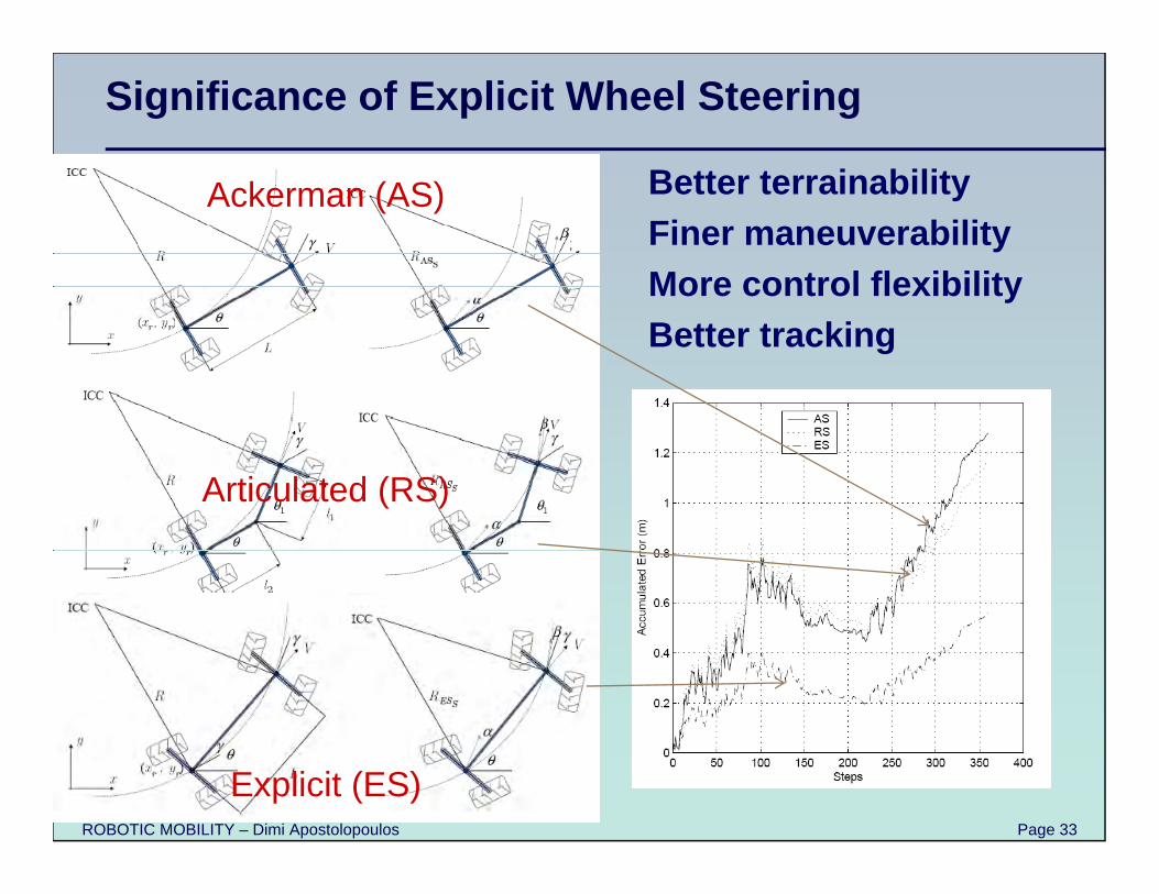
Significance of Explicit Wheel Steering
Better terrainabilityFiner maneuverabilityMore control flexibilityBetter tracking
Ackerman (AS)
Articulated (RS)
Explicit (ES)
ROBOTIC MOBILITY – Dimi Apostolopoulos Page 34
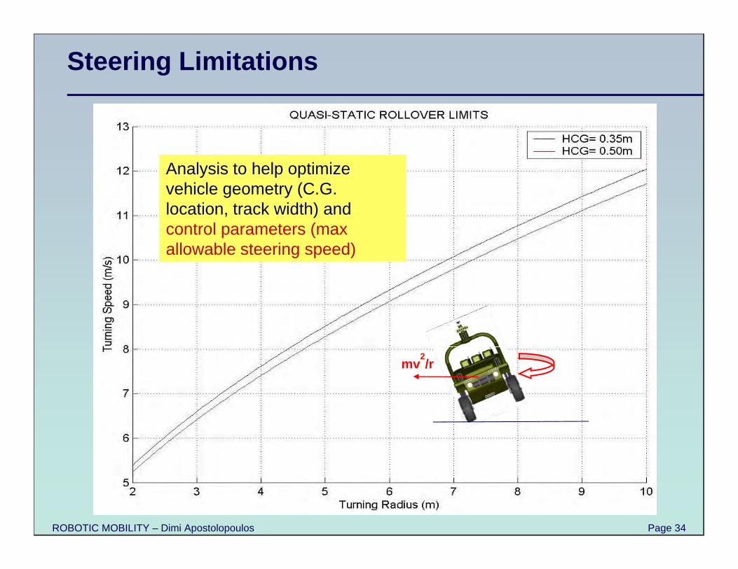
Steering Limitations
mv2/r
Analysis to help optimize vehicle geometry (C.G. location, track width) and control parameters (max allowable steering speed)
ROBOTIC MOBILITY – Dimi Apostolopoulos Page 35
Terrain Adaptation & Motion Smoothing
Optimal suspension geometry• Passive
Dynamic (spring/damper type)Geometric
• Passive with active adjustability
• Active
Elastic mobility elements
ROBOTIC MOBILITY – Dimi Apostolopoulos Page 36
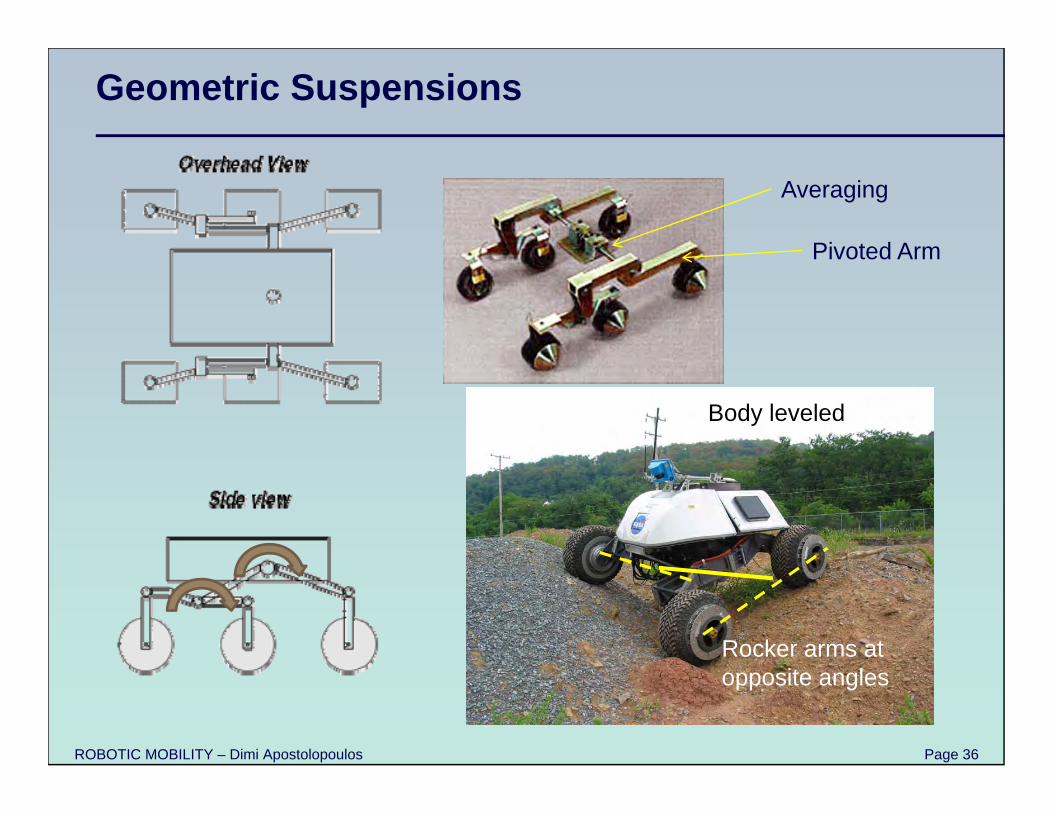
Geometric Suspensions
Averaging
Pivoted Arm
Body leveled
Rocker arms at opposite angles
ROBOTIC MOBILITY – Dimi Apostolopoulos Page 37
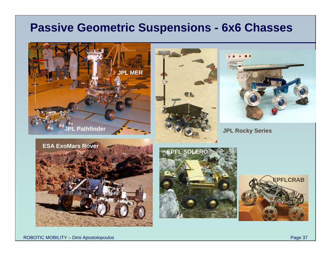
Passive Geometric Suspensions - 6x6 Chasses
JPL Pathfinder
JPL MER
JPL Rocky Series
ESA ExoMars RoverEPFL SOLERO
EPFLCRAB
ROBOTIC MOBILITY – Dimi Apostolopoulos Page 38
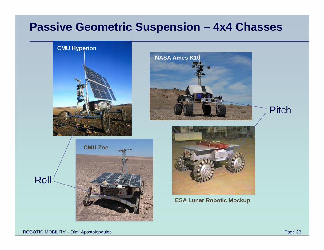
Passive Geometric Suspension – 4x4 ChassesCMU Hyperion
CMU Zoe
NASA Ames K10
ESA Lunar Robotic Mockup
Roll
Pitch
ROBOTIC MOBILITY – Dimi Apostolopoulos Page 39
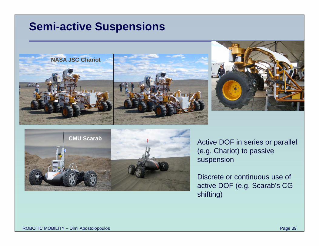
Semi-active Suspensions
NASA JSC Chariot
CMU Scarab Active DOF in series or parallel (e.g. Chariot) to passive suspension
Discrete or continuous use of active DOF (e.g. Scarab’s CG shifting)
ROBOTIC MOBILITY – Dimi Apostolopoulos Page 40
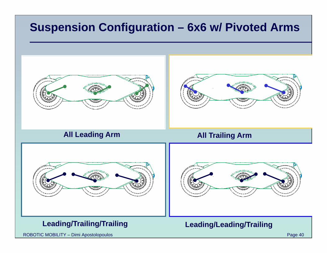
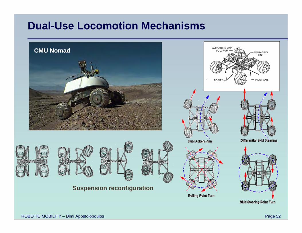
Suspension Configuration – 6x6 w/ Pivoted Arms
All Leading Arm All Trailing Arm
Leading/Trailing/Trailing Leading/Leading/Trailing
ROBOTIC MOBILITY – Dimi Apostolopoulos Page 41
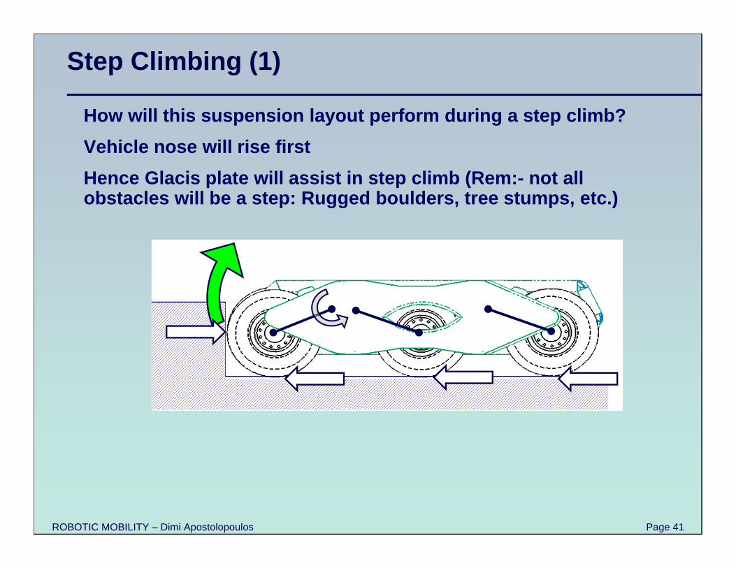
Step Climbing (1)
How will this suspension layout perform during a step climb?Vehicle nose will rise firstHence Glacis plate will assist in step climb (Rem:- not all obstacles will be a step: Rugged boulders, tree stumps, etc.)
ROBOTIC MOBILITY – Dimi Apostolopoulos Page 42
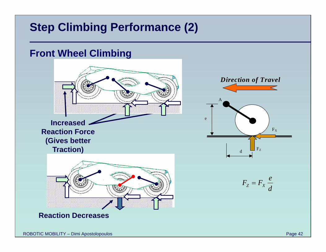
Step Climbing Performance (2)
Front Wheel Climbing
A
e
d FZ
FX
Direction of Travel
deFF XZ
Increased Reaction Force (Gives better
Traction)
Reaction Decreases
ROBOTIC MOBILITY – Dimi Apostolopoulos Page 43
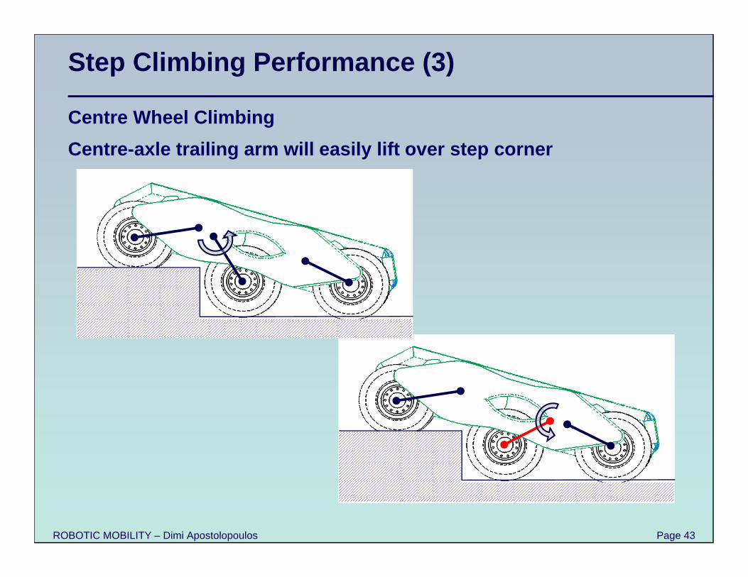
Step Climbing Performance (3)
Centre Wheel ClimbingCentre-axle trailing arm will easily lift over step corner
ROBOTIC MOBILITY – Dimi Apostolopoulos Page 44
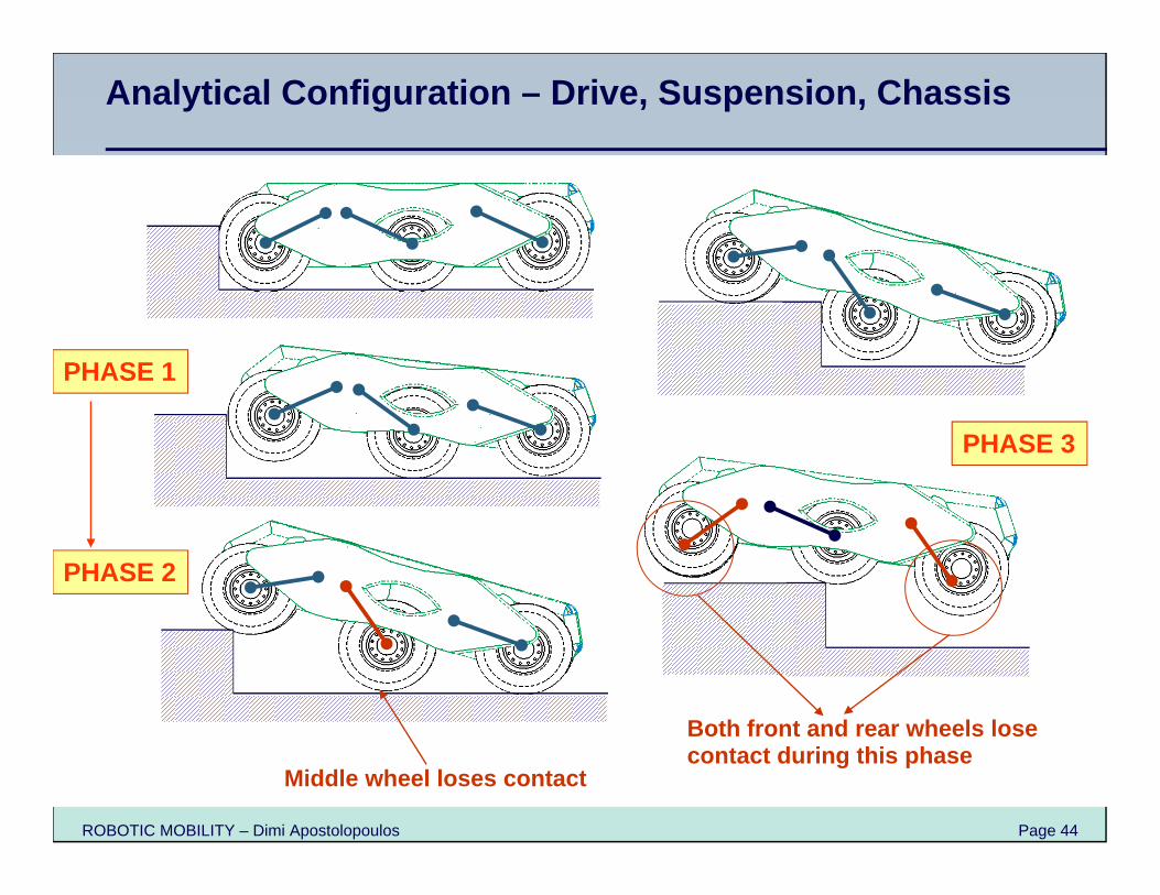
PHASE 1
Middle wheel loses contact
PHASE 2
PHASE 3
Both front and rear wheels lose contact during this phase
Analytical Configuration – Drive, Suspension, Chassis
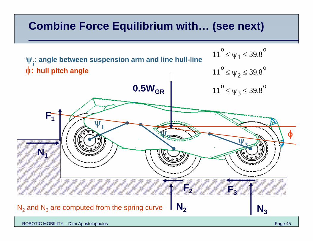
ROBOTIC MOBILITY – Dimi Apostolopoulos Page 45
12 3
11o
1 39.8o
11o2 39.8o
11o3 39.8o
i: angle between suspension arm and line hull-line: hull pitch angle
F1
N1
F2
N2
F3
N3
0.5WGR
N2 and N3 are computed from the spring curve
Combine Force Equilibrium with… (see next)
ROBOTIC MOBILITY – Dimi Apostolopoulos Page 46
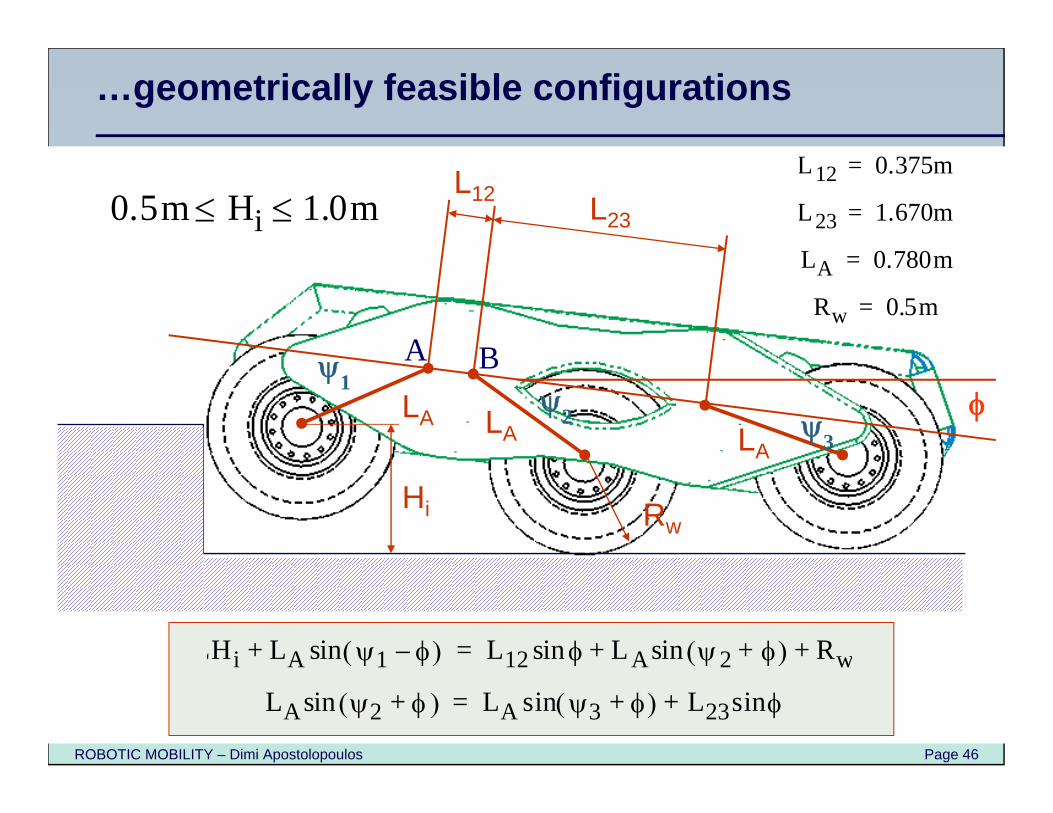
12 3
Hi
LA
L23
Rw
LALA
L12L12 0.375m=
L23 1.670m=
LA 0.780m=
Rw 0.5m=
0.5m Hi 1.0m
A B
LHi LA 1 – sin+ L12 sin LA 2 + sin Rw+ +=
LA 2 + sin LA 3 + sin L23 sin+=
…geometrically feasible configurations
ROBOTIC MOBILITY – Dimi Apostolopoulos Page 47
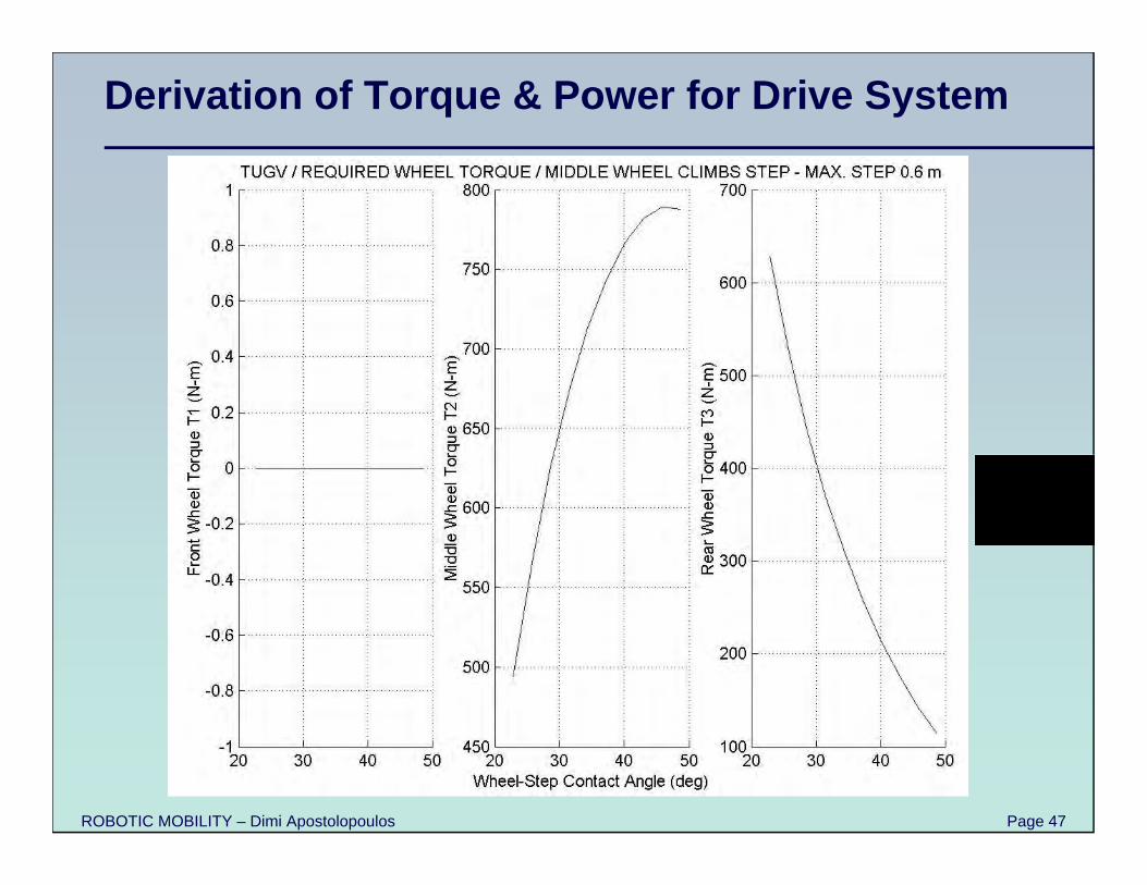
Derivation of Torque & Power for Drive System
ROBOTIC MOBILITY – Dimi Apostolopoulos Page 48
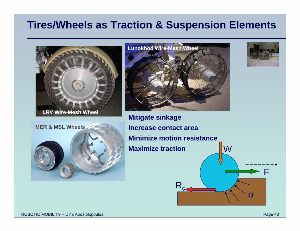
Tires/Wheels as Traction & Suspension Elements
LRV Wire-Mesh Wheel
Lunokhod Wire-Mesh Wheel
MER & MSL Wheels
Rc
W
F
σ
Mitigate sinkageIncrease contact areaMinimize motion resistanceMaximize traction
ROBOTIC MOBILITY – Dimi Apostolopoulos Page 49
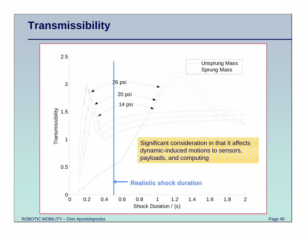
Transmissibility
0 0.2 0.4 0.6 0.8 1 1.2 1.4 1.6 1.8 20
0.5
1
1.5
2
2.5
Shock Duration / (s)
Tra
nsm
issi
bilit
yUnsprung MassSprung Mass
26 psi
20 psi
14 psi
Realistic shock duration
0 0.2 0.4 0.6 0.8 1 1.2 1.4 1.6 1.8 20
0.5
1
1.5
2
2.5
Shock Duration / (s)
Tra
nsm
issi
bilit
yUnsprung MassSprung Mass
26 psi
20 psi
14 psi
Realistic shock duration Realistic shock duration
Significant consideration in that it affects dynamic-induced motions to sensors, payloads, and computing
ROBOTIC MOBILITY – Dimi Apostolopoulos Page 50
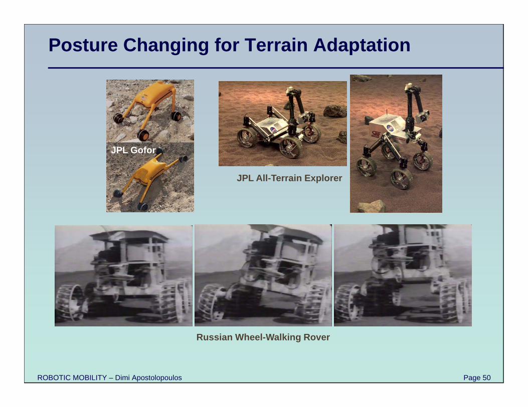
Posture Changing for Terrain Adaptation
JPL Gofor
JPL All-Terrain Explorer
Russian Wheel-Walking Rover
ROBOTIC MOBILITY – Dimi Apostolopoulos Page 51
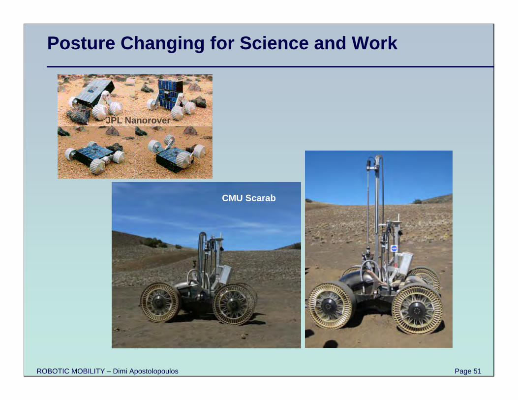
Posture Changing for Science and Work
JPL Nanorover
CMU Scarab
ROBOTIC MOBILITY – Dimi Apostolopoulos Page 52
CMU Nomad
Dual-Use Locomotion Mechanisms
Suspension reconfiguration
ROBOTIC MOBILITY – Dimi Apostolopoulos Page 53
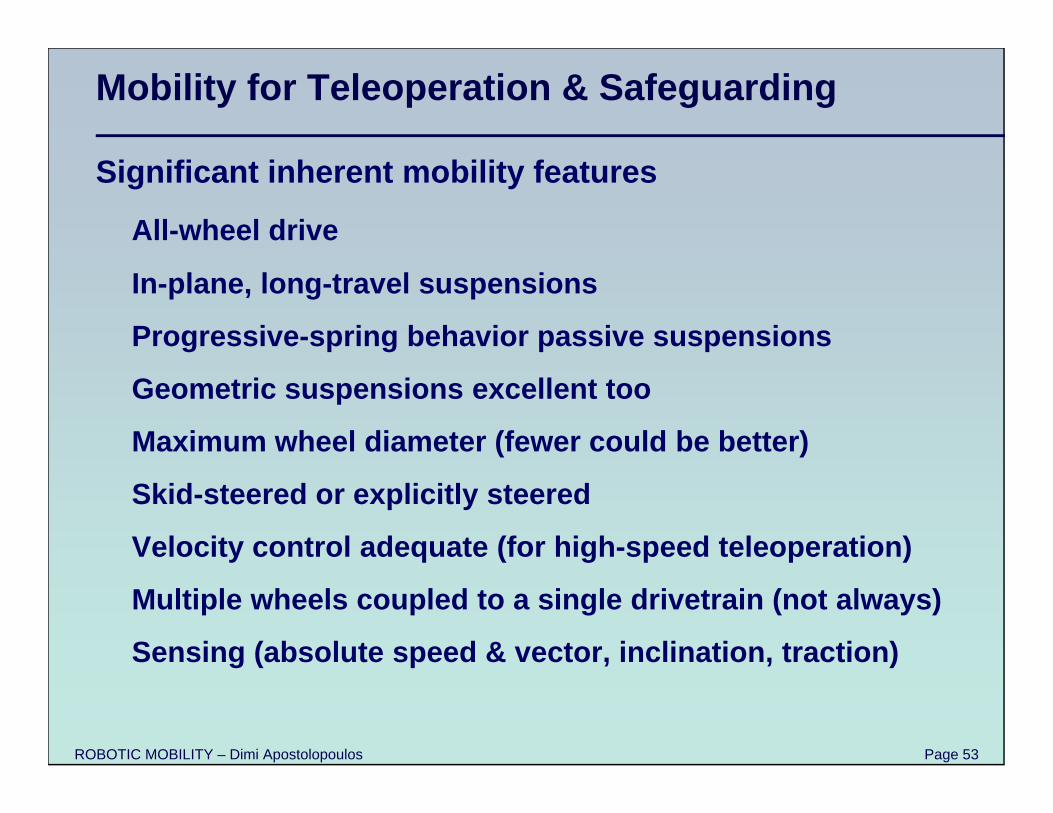
Mobility for Teleoperation & Safeguarding
Significant inherent mobility features
All-wheel drive
In-plane, long-travel suspensions
Progressive-spring behavior passive suspensions
Geometric suspensions excellent too
Maximum wheel diameter (fewer could be better)
Skid-steered or explicitly steered
Velocity control adequate (for high-speed teleoperation)
Multiple wheels coupled to a single drivetrain (not always)
Sensing (absolute speed & vector, inclination, traction)
ROBOTIC MOBILITY – Dimi Apostolopoulos Page 54
Closing Points
Well-designed mobility key to robotic performance
Use mechanics, geometry, analysis to design better robots
Rationalize subsystem selections
Blend methodological engineering and innovation to create high-performance systems
Test, test, test
Gladiator