Wheelchair accessible ATV - UC DRC Home
47
Wheelchair Accessible ATV A Baccalaureate thesis submitted to the School of Dynamic Systems College of Engineering and Applied Science University of Cincinnati in partial fulfillment of the requirements for the degree of Bachelor of Science in Mechanical Engineering Technology by Patrick Tribble August 2013 Thesis Advisor: Dr. Ahmed Elgafy
Transcript of Wheelchair accessible ATV - UC DRC Home
Wheelchair Accessible ATV
A Baccalaureate thesis submitted to the School of Dynamic Systems
College of Engineering and Applied Science University of Cincinnati
in partial fulfillment of the
requirements for the degree of
Bachelor of Science
in Mechanical Engineering Technology
by
Patrick Tribble
August 2013
Thesis Advisor: Dr. Ahmed Elgafy

ii
ACKNOWLEDGEMENTS
I would like to express my deep gratitude to Professor Elgafy, Chris Kubic, and the
volunteers with May We Help for their patient guidance, enthusiastic encouragement and
useful critiques of my research and my project. I would also like to thank Dean Arthur Allen
for his advice and time when I needed assistance. My grateful thanks are also extended to the
Mechanical Engineering Technology faculty for their feedback during my presentations.
I would also like to thank Brittany Franklin for her help with finding resources and
useful contacts to assist me with the concept designs and fabrication of my project.
Finally, I would like to thank my parents for allowing me to use their garage as a place to
work on and store my project.

iii
TABLE OF CONTENTS
ACKNOWLEDGEMENTS ...................................................................................................... II
TABLE OF CONTENTS ........................................................................................................ III
LIST OF FIGURES ................................................................................................................ IV
LIST OF TABLES ................................................................................................................... V
ABSTRACT ............................................................................................................................ VI
INTRODUCTION .................................................................................................................... 1
BACKGROUND .................................................................................................................................................... 1 INTERVIEWS ....................................................................................................................................................... 2
EXSISTING PRODUCTS ........................................................................................................ 3
SELF-MODIFIED PRODUCTS ................................................................................................................................ 3 EXISTING HANDICAPPED ACCESSIBLE PRODUCTS .............................................................................................. 4
CUSTOMER FEEDBACK, FEATURES, AND OBJECTIVES ............................................. 6
SURVEY ANALYSIS ............................................................................................................................................. 6 PRODUCT OBJECTIVES ........................................................................................................................................ 7 ENGINEERING CHARACTERISTICS ....................................................................................................................... 8
DESIGN .................................................................................................................................... 9
CONCEPT DESIGNS ............................................................................................................................................. 9 CURRENT DESIGN ............................................................................................................................................... 9
CALCULATIONS .................................................................................................................. 13
STARTING PARAMETERS ................................................................................................................................... 13 REQUIRED TORQUE & HORSEPOWER ................................................................................................................ 13 MOTOR & REDUCER SELECTION ...................................................................................................................... 14 BRAKING TORQUE ............................................................................................................................................ 14 POWERING OF THE SYSTEM ............................................................................................................................... 15 FORCES IN THE SYSTEM .................................................................................................................................... 16 DESIGN FACTOR ............................................................................................................................................... 18 MATERIAL SELECTION ..................................................................................................................................... 19
SYSTEM CHANGES ............................................................................................................. 20
POWERING OF THE SYSTEM CHANGES ............................................................................................................... 20 OBJECTIVES CHANGES ..................................................................................................................................... 20
FABRICATION ...................................................................................................................... 22
DE-ASSEMBLY OF THE ATV FRAME ................................................................................................................. 22 ASSEMBLY OF FRAME, CART, AND PLACEMENT ON THE ATV ......................................................................... 23 ATTACHMENT OF LAWNMOWER PARTS ............................................................................................................ 25
RESULTS ............................................................................................................................... 29
MOVEMENT TESTING ....................................................................................................................................... 29 WEIGHT TESTING ............................................................................................................................................. 29 FINAL PRODUCT ............................................................................................................................................... 29

iv
SCHEDULE AND BUDGET ................................................................................................. 31
SCHEDULE ........................................................................................................................................................ 31 BUDGET ............................................................................................................................................................ 32
WORKS CITED ..................................................................................................................... 33
APPENDIX A- RESEARCH .................................................................................................... 1
APPENDIX B – SURVEY WITH RESULTS ......................................................................... 1
APPENDIX C – QUALITY FUNCTION DEPLOYMENT .................................................... 1
APPENDIX D – PRODUCT OBJECTIVES ............................................................................ 2
APPENDIX E – SCHEDULE .................................................................................................. 1
APPENDIX F – BUDGET ....................................................................................................... 1
LIST OF FIGURES
Figure 1-Custom ATV (4) ........................................................................................................ 3
Figure 2-Custom ATV rear (4) ................................................................................................. 3
Figure 3 - 906 ELC Plunger Accelerator (5) ............................................................................ 4
Figure 4 – Classic Hand Control Knob Grip Straight Handle (Model 3501KB) (6) ................ 5
Figure 5 – First and Second Design Concepts .......................................................................... 9
Figure 6 – ATV cart design .................................................................................................... 10
Figure 7 – Frame Brackets ...................................................................................................... 10
Figure 8 – Frame of ATV ....................................................................................................... 11
Figure 9 – Rear axle mount ..................................................................................................... 11
Figure 10 – Front axle mount.................................................................................................. 12
Figure 11 – Top view of cart with rear axle and wheels attached .......................................... 12
Figure 12 – Reactions for three supports under evenly distributed load (8) ........................... 17
Figure 13 – Deflection diagram of the ATV cart .................................................................... 17
Figure 14 – Guidelines for Design Factor with ductile materials (9) ..................................... 19
Figure 15 – Disassembled front of ATV................................................................................. 22
Figure 16 – Disassembled rear of ATV .................................................................................. 22
Figure 17 – Disassembled middle section of ATV ................................................................. 23
Figure 18 – Disassembled ATV .............................................................................................. 23
Figure 19 – Attaching the frame to front of ATV ................................................................... 24
Figure 20 – Completed frame of ATV .................................................................................... 24
Figure 21 – 6061-T6 Cart welded together ............................................................................. 25
Figure 22 – Opening in cart with Styrofoam tubing around edges ......................................... 25
Figure 23 – Murray riding lawnmower ................................................................................... 26
Figure 24 – 11.5hp motor from riding lawnmower ................................................................ 26
Figure 25 – Lawnmower rear axle with tubing attached ........................................................ 27
Figure 26 – Lawnmower axle welded to ATV ....................................................................... 27
Figure 27 – Front end of lawnmower attached to rear ............................................................ 28
Figure 28 – Motor placed onto ATV with belt attached ......................................................... 28
Figure 29 – ATV final product (rear view) ............................................................................. 29

v
Figure 30 – ATV final product (front view) ........................................................................... 30
Figure 31 - Budget .................................................................................................................. 32
LIST OF TABLES
Table 1– Customer importance and customer satisfaction ratings 6
Table 2– Engineering characteristics 8
Table 3 – Senior Design Project Schedule 31

vi
ABSTRACT
Many handicapped individuals that cannot enjoy some of the simple task that most able
bodied people can achieve are now beginning to do what they love to do. This is being made
possible by the great volunteers of the May We Help organization. Ideas are brought to life
with a common goal of helping someone in need. A damaged all-terrain vehicle was to be
made of use to a wheelchair user. What better than to allow the wheelchair user to be able to
access the ATV just like any abled bodied person could? This question brought me to
designing and fabricating an ATV that could be driven by someone in a wheelchair while
they are in their chair.
Throughout the duration of the project the ATV was extended with use of steel rods and
an aluminum cart was fixed on the supports to allow a wheelchair user to fit inside. An old
lawnmower was then stripped of some components and then placed onto the ATV to power
the system. The end results were a very reliable structure with a bigger motor needed to run
the system. My research proves that with thought an reliable backing, more handicapped
individuals can do what they love to do regardless of their handicap.

Wheelchair Accessible Electric ATV Patrick Tribble
1
INTRODUCTION
BACKGROUND
Dean Allen Arthur of the University of Cincinnati, sent out a mass email to students
concerning an old all-terrain vehicle that was in a fire and could possibly be used for a senior
project. The meeting with Mr. Allen took place on September 17th, 2012 about the all-terrain
vehicle and possible senior design projects. Mr. Allen talked about an all-terrain vehicle that
was brought to his attention by the May We Help organization. He said the vehicle was in a
fire and the only working parts on the vehicle were the wheels, frame, and the brakes. He
also said that the organization wanted it to be run off electricity also, which meant the vehicle
would have to be converted. He contacted the organization and got times for which they were
open so the vehicle could be shown off and to get to know some of the people in the
organization.
The May We Help (1) group is a non-profit organization that is comprised of skilled
engineers and volunteers that gather together to create customized devices and adaptations
for people with specific needs at no cost. These include projects such as an indestructible
dressing stick for an individual with no arms, a children’s shower chair that was light enough
for the client to get in and out of the bathroom independently, and a computer and keyboard
stand designed to be used by a mouth stick user.
All-terrain vehicles are made for off-road driving such as in wooded, snow covered, or
swamp land type areas. With normal all-terrain vehicles, use by someone in a wheelchair or
with non-functioning legs would be very difficult. The user would have to get out of the
wheelchair and transfer their body into the vehicle. Without fully functioning legs, this would
be unsafe. Also, the user could not accelerate the vehicle because most all-terrain vehicles are
adapted for pedal usage. Essentially, if you are in a wheelchair you could not ride an all-
terrain vehicle.
This project with the My We Help organization would allow a user in a wheelchair or
who has non-functioning legs to operate and all-terrain vehicle while in their wheelchair. The
new modified all-terrain vehicle would have to work in a way where it gives the user the
same experience as if they were on a normal all-terrain vehicle. During the duration of this
project the goal is to work with the organization to make an all-terrain vehicle that can be
accessible by someone in a wheelchair or has non-functioning legs.

Wheelchair Accessible Electric ATV Patrick Tribble
2
INTERVIEWS
During this project several interviews were conducted. One with Associate
Dean/Professor of College of Engineering and Applied Science Allen Arthur (2) and the
second with Engineering Organization Coordinator Chris Kubic (3) with May We Help. Both
interviews were conducted in September in Cincinnati Ohio concerning project ideas,
concept designs, and introducing the all-terrain vehicle being worked on.
Chris Kubic is the engineering organization coordinator with May We Help. The
meeting took place on September 18th
, 2012 during an open house meeting at the May We
Help main office. There, the vehicle was presented and possible ideas were discussed about
how to go about working on the vehicle. The organization also showed off recent and past
projects to give a sense of what they do and some of the people they help. Mr. Kubic
explained that the vehicle was brought in by the owner with the thought of it being useful to
the organization to help someone in need. The engineers there then had the idea to turn the
normal ATV into an ATV that could be driven by someone with non-functioning legs. They
also expressed the idea that they wanted it to be run off of electricity so that there would be
no emissions. That way the user wouldn’t have to purchase gasoline. Once the project was
established and approved, the research began.

Wheelchair Accessible Electric ATV Patrick Tribble
3
EXSISTING PRODUCTS
SELF-MODIFIED PRODUCTS
There currently aren’t any all-terrain vehicles on the market that allow the user to be in-
chair while operating. But, there are vehicles out there that are custom built that give a
wheelchair user that ability.
Figure 1-Custom ATV (4)
Figure 2-Custom ATV rear (4)
Custom Ramp for
wheelchair access
Wheelchair user in chair while
operating
Hand controls for operation
All terrain capable

Wheelchair Accessible Electric ATV Patrick Tribble
4
Looking at these custom designs sparked ideas for different concept designs. Looking at this
concept design there are both positives and negatives. Some positives with the design are that
it fits in the frame of a regular ATV and that hand controls are incorporated to give the user
all the control that he could not normally use with non-functioning legs. The negative with
this concept design is that the person enters and exits the vehicle through the rear. This would
allow the vehicle to move while trying to enter and exit. With my design, I want to limit the
motion of the person in the wheelchair. With this design it seems as if the user would roll
around in the vehicle depending on the motion of the vehicle. Also, this design has the rider
entering from the rear of the ATV.
EXISTING HANDICAPPED ACCESSIBLE PRODUCTS
For the design, hand controls would have to be incorporated due to the fact the intended
user would not have functioning legs. Looking at existing products, there are hand
accelerators that work similar to a push button that allows the user to accelerate the vehicle
with their hands, and also a hand crank that operates as an accelerator and brake. The plunger
accelerator is an accelerator that can be mounted to the dashboard in a car and it allows the
user to accelerate the vehicle with their thumb. It also has an auto lock out feature for
emergency braking situations (figure3). The negatives with this design are that the design
would be hard to operate due to the fact that you are accelerating with your thumb instead of
your hand.
Figure 3 - 906 ELC Plunger Accelerator (5)
Plunger which controls
acceleration in some handicapped
accessible vehicles.

Wheelchair Accessible Electric ATV Patrick Tribble
5
This design is a hand control knob grip straight handle which works as an accelerator
and a brake. When pulling back on the knob you would accelerate the vehicle and when
pushing the knob away from you it would apply the break (figure4). This is also a
consideration that would be beneficial because you can do both operations with one handle.
The negatives with this design are that the device gets in the way and adds extra parts to the
vehicle which could lead to discomfort.
Figure 4 – Classic Hand Control Knob Grip Straight Handle (Model 3501KB) (6)
The knob that controls
acceleration and breaking in
some handicapped accessible
vehicles

Wheelchair Accessible Electric ATV Patrick Tribble
6
CUSTOMER FEEDBACK, FEATURES, AND OBJECTIVES
SURVEY ANALYSIS
All of the ten wheelchair surveys distributed were returned and analyzed for customer
needs. All of the surveys were completed by handicapped individuals who were in a
wheelchair (Appendix B has survey results). The survey asked the individual about the
importance of 12 product features that would be incorporated with my design and the
importance of those features in existing products that they currently use. The importance and
satisfaction were rated from 1 to 5 with 1 being low and 5 being high. The quality function
development shows the ratings of the customer importance and satisfaction on the right side
of the table. These numbers were generated based off customer feedback from the surveys.
Table 1– Customer importance and customer satisfaction ratings
The survey results showed that safety, reliability, easy to adjust, and different terrain
capable were the most important features to the customer. With the findings, new design
concepts will address the desirable features of the customer.
Customer Importance Ratings
Safe 4.6
Reliable 3.9
Easy to Adjust 3.8
Different terrain compatible 3.6
Durable 3.5
Easy to Operate 3.4
Maneuverable 3.3
Compatible with wheelchair 2.9
Affordable 2.9
Easy to Store 2.8
Comparible speed of commercial ATV 2.6
Reduce Emissions 2.4
Customer Satisfaction Ratings
Durable 3.8
Easy to Store 3.2
Affordable 3.1
Reliable 3.1
Safe 2.9
Easy to Adjust 2.7
Reduce Emissions 2.6
Maneuverable 2.6
Comparible speed of commercial ATV 2.4
Different terrain compatible 2.1
Easy to Operate 2.0
Compatible with wheelchair 1.9

Wheelchair Accessible Electric ATV Patrick Tribble
7
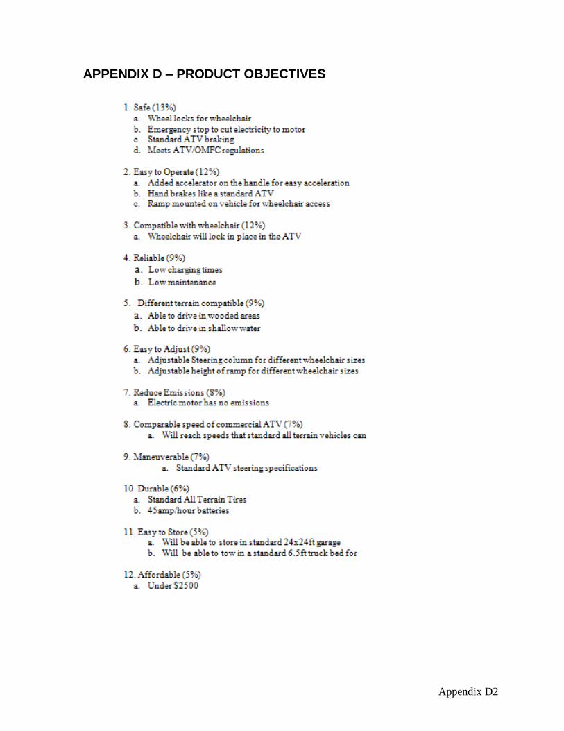
PRODUCT OBJECTIVES
The product objectives come from the list of features from the survey. The product
objectives are sorted by customer importance based off of survey results. Under each of the
listed features are the methods or intended designs that will be used in the prototype of the
vehicle.
1. Safe (12.5%)
a. Wheel locks for wheelchair
b. Emergency stop to cut electricity to motor
c. Standard ATV braking
d. Meets ATV/OFMC Regulations
2. Easy to Operate (11.9%)
a. Added accelerator on the handle for easy acceleration
b. Hand brakes like a standard ATV
c. Ramp mounted on vehicle for wheelchair access
3. Compatible with wheelchair (11.6%)
a. Wheelchair will lock in place in the ATV
4. Different terrain compatible (9.0%)
a. Able to drive in wooded areas
b. Able to drive in shallow water
5. Reliable (8.8%)
a. Low charging times
b. Low maintenance
6. Easy to Adjust (8.7%)
a. Adjustable Steering column for different wheelchair sizes
b. Adjustable height of ramp for different wheelchair sizes
7. Reduce Emissions (8.1%)
a. Electric motor has no emissions

Wheelchair Accessible Electric ATV Patrick Tribble
8
8. Maneuverable (6.7%)
a. Standard ATV steering specifications
9. Comparable speed of commercial ATV (6.5%)
a. Will reach speeds that standard all-terrain vehicles can
10. Durable ( 6.2%)
a. Standard All Terrain Tires
b. 45amp/hour batteries
11. Affordable (5.3%)
a. Under $2500
12. Easy to Store (4.6%)
a. Will be able to store in standard 24x24ft garage
b. Will be able to tow in a standard 6.5ft truck bed for
transportation
ENGINEERING CHARACTERISTICS
Table 2– Engineering characteristics
The results from the quality function development chart show that latches wheelchair in
ATV, adjustable steering column, large tires, and ramp mounted on ATV for wheelchair
access are the most weighted features. I believe if I incorporate most of my efforts into these
features that I will have a desirable product.
Engineering Characteristics
Latches wheelchair in ATV 2.62
Adjustable steering column 1.82
Large Tires 1.51
Ramp Mounted on ATV for wheelchair access 1.42
45 amp/hour batteries 1.35
Large wheel base with low outside wheel cut 1.34
Accelerator on the handle 1.08
Fully charged within 3 hours 0.80
Electric motor 0.73
Will reach speeds that standard all terrain vehicles can 0.59
Under $2500 0.47
Will be able to store in standard 24x24ft garage 0.42

Wheelchair Accessible Electric ATV Patrick Tribble
9
DESIGN
CONCEPT DESIGNS
Before selecting the final design, there were several other concept ideas that were drawn
up. With the intended usage of this project, there are only so many ways to go about
modifying the vehicle. To have and in chair design the frame must be modified to some
degree, there had to be some sort of ramp implemented that was able to open and close, and
at minimum had to be 3’ by 4 ‘ to satisfy manual wheelchair standard dimensions. With that
in mind, the first concept design had all three but the ramping mechanism and the entry point
were very difficult. In order for design one to work the back axel would have had to be
rebuilt entirely and extended several feet.
Figure 5 – First and Second Design Concepts
The second design shown in figure 6 allowed for a side entry which left open the
possibility of still leaving the rear axle intact. The brakes, wheels, and steering are still in
good condition on the vehicle and to keep those intact would save on funding. The second
design also had a turn style turntable that the vehicle would be locked in place to and would
turn into driver position once locked in. This was concept had a good principle to it but it was
just too difficult of a task to do. The turntable would have made the vehicle wider than
necessary. Both concepts had positives and negatives but they ultimately gave way to the
current design model.
CURRENT DESIGN
On the current model, side entry is installed for ease of entry and not having to
manufacture an extended rear axle. A locking ramp is in place so that the vehicle is
Design 1
Design 2

Wheelchair Accessible Electric ATV Patrick Tribble
10
accessible by a wheelchair. 3/8” thick plating is used for the base of the cart and the sides of
the cart are 1/8” thick. The cart bolts to the frame of the ATV by use of brackets that hold the
support beams in place.
Figure 6 – ATV cart design
The selected design will extend the ATV by 4ft giving it a total 7.5ft wheel base. This still
allows the vehicle to be stored in a standard garage and a standard truck bed.
Figure 7 – Frame Brackets

Wheelchair Accessible Electric ATV Patrick Tribble
11
Figure 8 – Frame of ATV
The vehicle is design to have a ramp that sits on the entry side of the vehicle which
collapses up by a catch and latch. The catch will be placed on the cart and when the ramp
extends upward and makes contact with the catch it will lock in place. The operator would
pull the ramp upward with a rope attached to the end of the ramp. The frame of the ATV is
designed to allow the whole cart structure to be bolted on and off and allow a means of
connecting the front and rear ends of the ATV.
Figure 9 – Rear axle mount

Wheelchair Accessible Electric ATV Patrick Tribble
12
Figure 10 – Front axle mount
Figure 11 – Top view of cart with rear axle and wheels attached
The motor will be mounted on the rear of the cart in front of the back axle mount and bar
tubing. This will allow the drive train to be closer to the motor.

Wheelchair Accessible Electric ATV Patrick Tribble
13
CALCULATIONS
STARTING PARAMETERS
Before beginning the calculations, certain limits and assumptions were made to establish
the parameters of the project. These included the desired speed, desired acceleration, wheel
chair size, gear ratio, shaft material, brake type, ATV weight, and the weight of the
individual operating the vehicle. The vehicle’s desired speed was to be close to the speed of a
normal ATV to give the user something close to the same experience. The Environmental
Protection Agency(EPA) states that an off –road vehicle is described as a vehicle that at least
reaches speeds of 25mph.With that in mind, the desired speed was set to a max of 25mph
with an acceleration of 10mph in 10 seconds. These parameters gave way to calculating the
actual acceleration and the revolutions per minute value at 25mph.
Desired speed = 25 MPH
Desired acceleration = 10 MPH in 10 seconds
= 10 Hour
Miles x 5280
Mile
Feet = 52800
Hour
Feet
= 5280 Hour
Feet x 1
Seconds
Hour
3600 = 14.67
Second
Feet
= 14.67 Second
Feet / 10 seconds = 1.47
2Second
Feet
REQUIRED TORQUE & HORSEPOWER
Once the vehicles acceleration was calculated, the force of the vehicle at that
acceleration was computed. This was done to determine the torque on the shaft from the
motor. For calculating total system weight, and assumption for the vehicle weight was made
by comparing a similar ATV with around the same size motor. With that assumption made,
the new electric motor weight was omitted and accounted for in the total ATV weight with
gasoline motor. The vehicle is designed to be used with a manual wheelchair and the max
weight the operator can be is 300 lbs.
Weight of the vehicle = ATV + Cart + Gearbox + Batteries + Wheelchair + Operator
= 324 lbs + 217 lbs + 20 + (40 lbs) x 2 + 45 lbs + max 300 lbs
= 986 lbs 31 slugs
At 1.47 2Second
Feet Force = 31 slugs x 1.47
2Second
Feet = 46 lbs
Torque = (Force x Distance) (46 lbs x 11″ Wheel Radius) = 506 in-lb
Once the required torque was established, then the horse power could be calculated by
taking the desired speed, converting from mph to rpm, then dividing the torque multiplied by
the rpm by 63000.

Wheelchair Accessible Electric ATV Patrick Tribble
14
ute
inches
ute
onds
onds
hourx
ft
inches
mile
ft
hour
miles
min26400
min1
sec60
sec3600
1
1
12528025
rpmute
inches
382"22
min26400
P = 63000
Re SpeedRotationalquiredTorque
= 63000
382506 3.06 horsepower
MOTOR & REDUCER SELECTION
Once required horsepower was obtained then the motor selection process began. At
minimum the system requires a 3 horsepower motor, so anything above 3 horsepower would
be acceptable. A 5hp electric AC single phase motor was selected that outputs 1725 rpm.
With this motor, it causes the output torque to be 183 in-lb. The minimum torque required to
move at the desired acceleration and speed is 506 in-lb. With the value of torque being below
the needed, a speed reducer was introduced into the system. The reducer chosen reduces at a
rate of 5:1 which increased the torque value from 183 in-lb to 913 in-lb.
T = rpm
horsepower
1725
563000 183 in-lb
T = rpm
horsepower
1725
5563000 913 in-lb
BRAKING TORQUE
The braking torque for the new motor would be different from the torque caused by the
old, therefore the new braking torque would have to be calculated to see if the existing
system could supply the force needed. This was calculated by taking the horsepower of the
motor and multiplying it with a service factor and the conversion factor 63025. Once that
number was obtained, it was divided by the rear axle’s speed. For brakes under average
conditions it is recommended to use a service factor of 1.0.
Braking Torque = rpm
torServiceFacHorsepower63025

Wheelchair Accessible Electric ATV Patrick Tribble
15
Braking Torque = 382
1563025 827 in-lb
The EPA states that, “ATV or off-road vehicle should have a braking horsepower equal
less than or equal to 30kw or 40hp (7)”. With this regulation, the max braking force of the
current brakes would be:
Braking Torque = 382
14063025 6599 in-lb
With the ATV complying with these regulations, the braking system will be able to handle
the new motors torque and bring the vehicle to a stop.
POWERING OF THE SYSTEM
With the motor selected, an accompanying power source had to be applied for the motor
to work. To power the system car batteries and an inverter will be placed on the vehicle to
supply the correct voltage to the motor. Since the car batteries supply DC voltage, an inverter
is needed to convert to AC voltage for the motor to use. The operating voltage of the motor is
208-230V AC at 60Hz power. This means that two 12V DC car batteries would be needed to
convert to 240V AC for the motor to work. A 24V DC to 220/240AC inverter was selected.
This would supply the correct voltage needed for the system to work with only two car
batteries required. Each battery has a reserve capacity of 170 minutes. This is the time it
takes for the battery to discharge until it reaches below its rated voltage. This means that you
could use the batteries at a rate of 25 amps for 340 minutes with two batteries. The motor
requires 21full load amps to reach max horsepower. So, at max hp, the system has a usage of
5 hours and 40 minutes. The two batteries will be placed on the outside of the ATV where
the front rack is located. Then, the inverter will be mounted on the left side of the front rack
so the wire from the batteries to the inverter is a short distance. A wire would then be run
from the inverter to the back of the cart where the motor lies. This would complete the circuit
and power the system.
Two Batteries = 24V
Inverter converts 24V DC to 220/240V AC
Motor uses 208-230V AC so the system would have the power necessary to work

Wheelchair Accessible Electric ATV Patrick Tribble
16
FORCES IN THE SYSTEM
With the torque requirements met, the forces exerted from the torque on the shaft had to
be calculated. With a rotating member, torsional shear, bending, and tensile stress will be
present.
Tmax = J
aftRadiusofshTorque
Tmax = 4035.2
320175.1913
553 psi
Bending = ulusSectionMod
MaxMoment
Bending = 3035.2
3271288
86163 psi
Tensile = Area
Force 2035.2
4986
303.2 psi
The other members in the system that force will be exerted on the most will be the
bottom supports of the cart, and the base plate of the cart. At the supports there will be
deflection, shear, and bending stress from the distribution of the weight of the base plate
assembly with in-chair operator. At the base plate there will be bending stress from the front,
back, and side plates along with an in-chair operator. The deflection calculations were
calculated by using the figure below.

Wheelchair Accessible Electric ATV Patrick Tribble
17
Figure 12 – Reactions for three supports under evenly distributed load (8)
Figure 13 – Deflection diagram of the ATV cart

Wheelchair Accessible Electric ATV Patrick Tribble
18
L = 24 in
X1 = L4215.0 10.116 in
E = 30457924 psi
I = 64
4D .049
Deflection = 049.1030185
244576
4
x -.557 in
Reaction at B = 2445725.1 13710 psi
Reaction at A = Reaction at C = 8
244573 4113 psi
Moment at B = 224681125.0 12309 in-lb clockwise
Moment at A = Moment at C = 2025.126810703.0 6922 in-lb
Max Bending Stress = ulusSectionMod
MaxMoment 3035.2
3212309
14877 psi
Bending stress in base plate = ulusSectionMod
MaxMoment 23648
614232
1.37 psi
DESIGN FACTOR
With the forces on the system calculated, a design factor for the modifying parts had to
be selected. With the operator being physically impaired, it was assumed that when off-road
driving that the conditions be moderately normal with few obstructions which would reduce
impact and shock. My modifications are giving the operator the ability to experience riding
in an ATV in off-road conditions but not extreme conditions where there would be heavy
amounts of impact and shock. With these assumptions assumed, a design factor of 3 was
chosen. For ductile materials a recommended set of design factors is supplied in the figure
below. The design factor 3 will be adequate for the intended design usage.

Wheelchair Accessible Electric ATV Patrick Tribble
19
Figure 14 – Guidelines for Design Factor with ductile materials (9)
MATERIAL SELECTION
With design factor chosen, the material for each component was selected. The selection
process of the material was based off of three factors. These factors are cost, design factor,
and forces obtained. The first material selected was the material of the support rods that run
along the bottom of the cart. The material chosen for the supports was high-strength 1045
carbon steel which has yield strength of around 77 ksi. The max stress the supports come
under is 14877 psi. If the yield strength of the material is divided by the design factor 3, the
value obtained is above the intended stress. This makes the material acceptable for use in the
supports.
Design Stress = orDesignFact
gthYieldStren =
3
900,76 25,633 psi
With the support material chosen the next material analyzed was the cart. The cart
includes the base plate, front panel, side panel, and back panel. The material chosen for all
four sides should be the same material for ease of welding the components together. To
reduce weight, aluminum materials were looked at because of their moderate strength with
low weight. The aluminum selected was 6061-T6 grade. The 6061 is adequate enough to
handle all the stress and forces on the cart body. The cart will not see as many forces as the
axel or supports so material was choose based on reduction of weight in the system. The
yield strength of the 6061-T6 is 40,000 psi which gives a design stress of 13,333 psi. This
makes the material acceptable for this application.
Various parts of the cart such as the support brackets and the axle mounts will be made
of 1018 steel. 1018 steel has a yield stress of 53,700 psi which gives it a design stress of
17,900 psi. The support brackets and axle mounts are there just as a means to connect the
existing ATV to the frame of the cart and the forces exerted on these members will not be
critical. The material will be suitable for the application.

Wheelchair Accessible Electric ATV Patrick Tribble
20
SYSTEM CHANGES
POWERING OF THE SYSTEM CHANGES
The means to make the vehicle run by electric were too costly and the AC power would
not have been strong enough to sustain the vehicle for long periods of time as previously
thought. With these factors, the decision was made to go with a gasoline powered system to
reduce cost and to have longer usage times than with electricity. A Murray riding lawn
mower was purchased and stripped of its motor along with parts of the frame which were
used on the ATV. The motor of the riding lawn mower is rated at 11hp and rotates at max
2800 rpm. This will be adequate to power the system with at least a 3:1 speed reducer.
T = rpm
horsepower
2800
1163000 247.5 in-lb
T = rpm
horsepower
2800
31163000 742.5in-lb
OBJECTIVES CHANGES
With this change, the objectives of the project had to be restated also. The reduce
emissions, parts of durability, and reliability had to be changed from the previous objectives
to meet with current requirements.
1. Safe (12.5%)
a. Wheel locks for wheelchair
b. Emergency stop to cut electricity to motor
c. Standard ATV braking
d. Meets ATV/OFMC Regulations
2. Easy to Operate (11.9%)
a. Added accelerator on the handle for easy acceleration
b. Hand brakes like a standard ATV
c. Ramp mounted on vehicle for wheelchair access
3. Compatible with wheelchair (11.6%)
a. Wheelchair will lock in place in the ATV
4. Different terrain compatible (9.0%)
a. Able to drive in wooded areas
b. Able to drive in shallow water

Wheelchair Accessible Electric ATV Patrick Tribble
21
5. Reliable (8.8%)
a. Low maintenance
6. Easy to Adjust (8.7%)
a. Adjustable Steering column for different wheelchair sizes
b. Adjustable height of ramp for different wheelchair sizes
7. Maneuverable (6.7%)
a. Standard ATV steering specifications
8. Comparable speed of commercial ATV (6.5%)
a. Will reach speeds that standard all-terrain vehicles can
9. Durable ( 6.2%)
a. Standard All Terrain Tires
10. Affordable (5.3%)
a. Under $2500
11. Easy to Store (4.6%)
a. Will be able to store in standard 24x24ft garage
b. Will be able to tow in a standard 6.5ft truck bed for

Wheelchair Accessible Electric ATV Patrick Tribble
22
FABRICATION
DE-ASSEMBLY OF THE ATV FRAME
The first step of fabrication was to disassemble the ATV into pieces. Old wires were
trimmed from the frame and bolts were removed to take off components not needed. The
front of the frame was disassembled first.
Figure 15 – Disassembled front of ATV
Once the front of the ATV was removed the rear was removed which gave the necessary
pieces to start fabrication of the wheelchair ATV.
Figure 16 – Disassembled rear of ATV

Wheelchair Accessible Electric ATV Patrick Tribble
23
Figure 17 – Disassembled middle section of ATV
Figure 18 – Disassembled ATV
ASSEMBLY OF FRAME, CART, AND PLACEMENT ON THE ATV
Once the ATV was in separate pieces, the lower frame was assembled and welded on to
the front section of the disassembled ATV. The lower frame was made by making three
carbon steel brackets by bending plates 90 degrees down the center. Once bent, the carbon
steel was drilled three times to allow the supports to slide through them. With the supports
through the brackets, each support was welded to the brackets at each hole location. The
front axle mount was then placed onto the supports to allow connection to the upper section
of the ATV. A steel section of tubing was also placed on the edge of the supports to allow for
connection to the rear section of the ATV.

Wheelchair Accessible Electric ATV Patrick Tribble
24
Figure 19 – Attaching the frame to front of ATV
When the front end of the vehicle was attached the lower frame, the front end was raised
and to allow the correct placement. Once a solid weld was run then the frame was lowered
and the rear section of the ATV was welded on.
Figure 20 – Completed frame of ATV
Once the frame was completed, the 6061-T6 aluminum cart was welded together and
had 6 holes drilled on the bottom so that it could be bolted onto the frame. This was chosen
to be done this way to have a means to remove the cart if the cart were to be damaged
somehow. This way it could be replaced without having to replace the frame.

Wheelchair Accessible Electric ATV Patrick Tribble
25
Figure 21 – 6061-T6 Cart welded together
Once the cart was attached to the frame, the cart’s front section was cut to allow access
to the steering wheel. Styrofoam tubing was then placed along the jagged edges of the cut
frame so that the user would not get cut while operating. A ramp was supposed to be placed
on the side of the cart but a means to do so would have been too expensive and taken up too
much time to meet deadline dates. Therefore, the ramp was excluded during the duration of
the project.
Figure 22 – Opening in cart with Styrofoam tubing around edges
ATTACHMENT OF LAWNMOWER PARTS
Due to the cost of making the ATV run off of electricity, a Murray riding lawnmower

Wheelchair Accessible Electric ATV Patrick Tribble
26
was stripped of its rear axle, front end, and an 11.5hp motor to be placed onto the ATV so
that the motor could be used to run the system. The new plan was to implement the same
system as the riding lawnmower to push the ATV by using a pulley clutch attached to the
drive shaft of the motor which would be connected to the lawnmowers rear axle by a belt. A
sawzall, screwdriver, and ratchets were used to remove the needed pieces from the
lawnmower.
Figure 23 – Murray riding lawnmower
The 11.5hp motor was removed first so that the other components could be easily taken
off without an issue of damaging the motor. Bolts fastening the motor to the body of the
lawnmower were removed, along with the drive belt and pulleys which freed up the motor to
be removed.
Figure 24 – 11.5hp motor from riding lawnmower
The next step in fabrication was to remove the rear axle. A sawzall was run through the

Wheelchair Accessible Electric ATV Patrick Tribble
27
rear of the lawnmower to remove the plastic body from the rear axle and bolts were removed
from the body, which were fastened to the axle, which freed the axle. Once the axle was
removed, steel tubing was connected to the axle to allow a means to connect to the rear of the
ATV.
Figure 25 – Lawnmower rear axle with tubing attached
Once the lawnmower parts were ready to be attached, the existing axle of the ATV was
removed so that steel tubing could be placed on to allow connection. When the proper
alignment was made the tubing pieces were welded together.
Figure 26 – Lawnmower axle welded to ATV
With the front end of the lawnmower removed, the next step was to place it onto the rear
of the ATV so that the motor could be placed on top of it and line up with the rear axle
pulley. This way motion could be achieved when the motor makes rotation, and drive the
wheels.

Wheelchair Accessible Electric ATV Patrick Tribble
28
Figure 27 – Front end of lawnmower attached to rear
The final part of reconstruction was to place the motor onto the rear of the ATV. The
pulley clutch was attached to the shaft of the motor and holes were drilled into the top
portion of the lawnmower so that the motor could be bolted down. Once bolted down, a belt
was sized and placed onto the rear axle pulley and clutch.
Figure 28 – Motor placed onto ATV with belt attached

Wheelchair Accessible Electric ATV Patrick Tribble
29
RESULTS
MOVEMENT TESTING
The planned testing of the ATV was to turn on the motor and see how fast it could
accelerate, stop, and the ease of turning on and off. The 11.5hp motor was not able to start up
so a new motor was purchased and placed on the system. The new motor is a 5.5hp motor so
accurate testing of the system could not be made. The new motor was able to move the
weight of the ATV with a chair placed on the inside of the cart but with a weight applied
(230lbs) it was able to move about a half a foot or so. With the old motor fixed the system
will be able to tow the design weight of at least 300lbs.
WEIGHT TESTING
The frame was tested by placing my weight plus a wheel chair into the cart and
observing if the system would give out or yield. The frame was sturdy while just sitting in the
wheelchair, so a shock test was made. While in the cart standing, I began to jump up and
down repeatedly to see if the cart would buckle or give. The frame withstood the shock and
was able to do so without deforming. The results of these test show that the frame is able to
handle the necessary stresses to operate properly.
FINAL PRODUCT
Below are the images of the final product with the replacement motor mounted onto the
rear, and the front view with Styrofoam tubing placed along the edges.
Figure 29 – ATV final product (rear view)

Wheelchair Accessible Electric ATV Patrick Tribble
30
Figure 30 – ATV final product (front view)

Wheelchair Accessible Electric ATV Patrick Tribble
31
SCHEDULE AND BUDGET
SCHEDULE
The project schedule begins on November 8, 2012 with meeting with the advisor for
proof of design and ends on August 2nd
, 2013 with project completion.
Table 3 – Senior Design Project Schedule
November December January February March April May June July August
Proof of Design to advisor 8
Concept sketches to advisor 15
Choose best concept design 20
Solidworks modeling 8
Design freeze 15
Desing Calculations 5 2
Order components 1
Assembly of ATV cart 14
Testing of Frame 30
Tech Expo 4
Redesign/Assembly of cart 7
Summer extension granted 24
Testing of ATV 12
Redesign of motor operation 22
Purchase of new motor 12
Re-test of the ATV w/new motor 18
Project Completion 2
Wheelchair Accessible Electric ATV Patrick Tribble
32
BUDGET
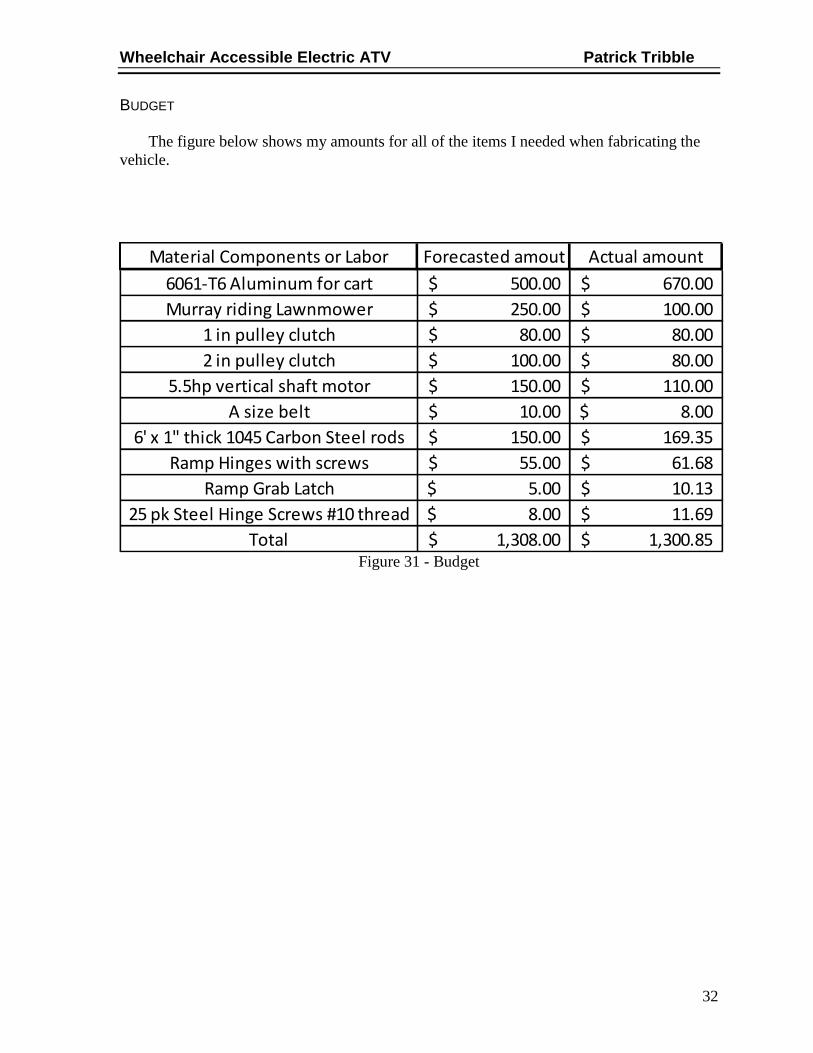
The figure below shows my amounts for all of the items I needed when fabricating the
vehicle.
Figure 31 - Budget
Material Components or Labor Forecasted amout Actual amount
6061-T6 Aluminum for cart 500.00$ 670.00$
Murray riding Lawnmower 250.00$ 100.00$
1 in pulley clutch 80.00$ 80.00$
2 in pulley clutch 100.00$ 80.00$
5.5hp vertical shaft motor 150.00$ 110.00$
A size belt 10.00$ 8.00$
6' x 1" thick 1045 Carbon Steel rods 150.00$ 169.35$
Ramp Hinges with screws 55.00$ 61.68$
Ramp Grab Latch 5.00$ 10.13$
25 pk Steel Hinge Screws #10 thread 8.00$ 11.69$
Total 1,308.00$ 1,300.85$

Wheelchair Accessible Electric ATV Patrick Tribble
33
WORKS CITED 1. May We Help. May We Help . [Online] [Cited: September 20, 2012.]
www.maywehelp.org.
2. Allen, Arthur. Possible Senior Project . Cincinnati, September 17, 2012.
3. Kubic, Chris. Wheelchair Accessible Electric ATV. Cincinnati, September 18, 2012.
4. 6x6 World. 6x6 World. [Online] [Cited: September 26, 2012.]
http://www.6x6world.com/gallery/argo-6-and-8-wheelers/p15539-wheelchair-accessible-
argo.html.
5. Ride-away. Ride-away Web site. [Online] [Cited: October 1, 2012.] http://www.ride-
away.com/products/driving-controls/guidosimplex/guidosimplex.php.
6. Able Data. Able Data website. [Online] [Cited: October 1, 2012.]
http://www.abledata.com/abledata.cfm?pageid=19327&top=13914&ksectionid=19327&prod
uctid=205666&trail=0&discontinued=0.
7. Environmental Protection Agency . Environmental Protection Agency web site. [Online]
[Cited: January 22, 2012.] http://www.epa.gov/nonroad/recveh/1-applicable-regs.pdf.
8. Mott, Robert L. Applied Strength of Materials. Upper Saddle River : Pearson Prentice
Hall, 2008. 0-13-236849-8.
9. —. Machine Elements in Mechanical Design. Upper Saddle River : Pearson Prentice Hall,
2004. 0-13-061885-3.

Appendix A1
APPENDIX A- RESEARCH
Interview with Engineering Organization Coordinator: Chris Kubic with May We Help
7525 Wooster Pike Cincinnati, Ohio 45227 9/18/12
He is the organizer of projects for the May We Help Organization. He has coordinated many
projects dealing with handicapped individuals and is also an engineer.
We talked about the tasks of the project and possible ideas of how to go about completing it.
To start off, he suggested stripping the ATV of its gasoline components and of its
transmission. Next task would be to design a new frame for the vehicle or to use the existing
frame and build an add on to it. Once the frame was figured out, then we talked about
putting the electric components into the vehicle, possible using 3-4 car batteries to power it.
When talking about design requirements, we both agreed that the ATV would have to have
hand controls due to the fact that the intended user would have non-functioning legs. We
also mentioned that the modified ATV should be easy to access by a wheelchair
user/individual with non-functioning legs and maybe a possible way to store the wheelchair
while the user is riding. Since the braking system on the ATV is functional, we talked about
possibly keeping that intact and maybe making small modifications to it if necessary.
He felt that the project upon completion would make the user it is for feel more able bodied
and give them the ability to do something that would normally be non-feasible.
Meeting with Associate Dean/Professor of College of Engineering and Applied Science:
Arthur Allen
7147 Garden Rd Cincinnati, OH 45236 9/17/12
We spoke about the project and ways to go about doing the project. He was alerted about the
project by the May We Help organization and he gave me the contact information of the
organization.
He suggested using an accelerator on the handle as the way to accelerate and also using the
transmission from a motorized wheelchair for use in the ATV. He also suggested keeping
the working parts of the ATV and just modifying the components that didn’t work.

Appendix A2
Custom Wheelchair Accessible Argo 8-wheeler
This is a custom ATV made for a person in a
wheelchair. With this design the intended user is to be
in the wheelchair while using. The ATV has a
collapsible ramp attached to the end for traveling in
and out of the ATV.
Custom ATV (4)
Custom ATV rear (4)
Design allows the user to move
while in the ATV.
My design would allow the user
to be out of the chair to give the
user a more comfortable
experience and eliminate rolling
inside of the ATV.
My design will be run off of
electric power.
Appendix A3
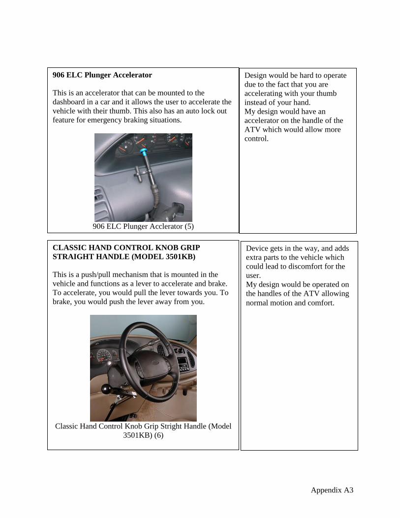
906 ELC Plunger Accelerator
This is an accelerator that can be mounted to the
dashboard in a car and it allows the user to accelerate the
vehicle with their thumb. This also has an auto lock out
feature for emergency braking situations.
906 ELC Plunger Acclerator (5)
Design would be hard to operate
due to the fact that you are
accelerating with your thumb
instead of your hand.
My design would have an
accelerator on the handle of the
ATV which would allow more
control.
CLASSIC HAND CONTROL KNOB GRIP
STRAIGHT HANDLE (MODEL 3501KB)
This is a push/pull mechanism that is mounted in the
vehicle and functions as a lever to accelerate and brake.
To accelerate, you would pull the lever towards you. To
brake, you would push the lever away from you.
Classic Hand Control Knob Grip Stright Handle (Model
3501KB) (6)
Device gets in the way, and adds
extra parts to the vehicle which
could lead to discomfort for the
user.
My design would be operated on
the handles of the ATV allowing
normal motion and comfort.

Appendix B1
APPENDIX B – SURVEY WITH RESULTS
Handicapped Accessible ATV
Customer Survey
The purpose of this survey is to gauge customer interest in an electric handicapped accessible
all terrain vehicle. Below is a list of features that the vehicle will incorporate.
How important is each feature to you for the design of a handicapped accessible ATV ?
Please circle the appropriate answer. 1 = low importance 5 = high importance
Averages
Safe 1(0) 2(0) 3(1) 4(2) 5(7) N/A(0) 4.6
Easy to Operate 1(2) 2(1) 3(1) 4(3) 5(3) N/A(0) 3.4
Reliable 1(1) 2(1) 3(1) 4(3) 5(5) N/A(0) 3.9
Durable 1(1) 2(1) 3(3) 4(2) 5(3) N/A(0) 3.5
Maneuverable 1(1) 2(1 3(3) 4(4) 5(1) N/A(0) 3.3
Easy to Store 1(2) 2(2) 3(3) 4(2) 5(1) N/A(0) 2.8
Compatible with wheelchair 1(3) 2(1) 3(3) 4(0) 5(3) N/A(0) 2.9
Reduce Emissions 1(3) 2(3) 3(2) 4(1) 5(1) N/A(0) 2.4
Comparable speed of commercial ATV 1(2) 2(3) 3(3) 4(1) 5(1) N/A(0) 2.6
Different terrain compatible 1(2) 2(1) 3(1) 4(5) 5(1) N/A(0) 3.6
Easy to Adjust 1(1) 2(1) 3(1) 4(3) 5(4) N/A(0) 3.8
Affordable 1(3) 2(1) 3(2) 4(2) 5(2) N/A(0) 2.9
How satisfied are you with the current wheelchair accessible vehicles?
Please circle the appropriate answer. 1 = very unsatisfied 5 = very satisfied
Averages
Safe 1(2) 2(2) 3(1) 4(5) 5(0) N/A(0) 2.9
Easy to Operate 1(4) 2(2) 3(4) 4(0) 5(0) N/A(0) 2.0
Reliable 1(2) 2(1) 3(2) 4(4) 5(1) N/A(0) 3.1
Durable 1(0) 2(1) 3(2) 4(5) 5(2) N/A(0) 3.8
Maneuverable 1(3) 2(0) 3(6) 4(0) 5(1) N/A(0) 2.6
Easy to Store 1(2) 2(2) 3(1) 4(2) 5(3) N/A(0) 3.2
Compatible with wheelchair 1(4) 2(3) 3(1) 4(1) 5(0) N/A(1) 1.9
Reduce Emissions 1(2) 2(2) 3(4) 4(2) 5(0) N/A(0) 2.6
Comparable speed of commercial ATV 1(3) 2(2) 3(1) 4(3) 5(0) N/A(1) 2.4
Different terrain compatible 1(5) 2(2) 3(1) 4(1) 5(1) N/A(0) 2.1
Easy to Adjust 1(1) 2(3) 3(4) 4(2) 5(0) N/A(0) 2.7
Affordable 1(2) 2(1) 3(4) 4(0) 5(3) N/A(0) 3.1

Appendix D1
APPENDIX C – QUALITY FUNCTION DEPLOYMENT
Latc
hes w
heelc
hair in A
TV
Adju
sta
ble
ste
ering c
olu
mn
Fully c
harg
ed w
ithin
3 h
ours
Larg
e T
ires
Ele
ctr
ic m
oto
r
45 a
mp/h
our
batt
eries
Accele
rato
r on t
he h
andle
Under
$2500
Larg
e w
heel base w
ith low
outs
ide w
heel cut
Will be a
ble
to s
tore
in s
tandard
24x24ft
gara
ge
Ram
p M
ounte
d o
n A
TV
for
wheelc
hair a
ccess
Will re
ach s
peeds t
hat
sta
ndard
all t
err
ain
vehic
les c
an
Custo
mer
import
ance
Curr
ent
Satisfa
ction
Pla
nned S
atisfa
ction
Impro
vem
ent
ratio
Modifie
d I
mport
ance
Rela
tive w
eig
ht
Rela
tive w
eig
ht
%
Safe 9 3 4.6 2.9 4.5 1.6 7.1 0.1 13%
Easy to Operate 9 3 9 3.4 2.0 4.0 2.0 6.8 0.1 12%
Reliable 3 9 9 3.9 3.1 4.0 1.3 5.0 0.1 9%
Durable 3 9 9 3.5 3.8 3.8 1.0 3.5 0.1 6%
Maneuverable 9 3.3 2.6 3.0 1.2 3.8 0.1 7%
Easy to Store 3 9 2.8 3.2 3.0 0.9 2.6 0.0 5%
Compatible with wheelchair 9 9 3 2.9 1.9 4.3 2.3 6.6 0.1 12%
Reduce Emissions 9 2.4 2.6 5.0 1.9 4.6 0.1 8%
Comparible speed of commercial ATV 9 2.6 2.4 3.5 1.4 3.7 0.1 7%
Different terrain compatible 9 3.6 2.1 3.0 1.4 5.1 0.1 9%
Easy to Adjust 9 3.8 2.7 3.5 1.3 4.9 0.1 9%
Affordable 9 2.9 3.1 3.2 1.0 3.0 0.1 5%
Abs. importance 2.62 1.82 0.80 1.51 0.73 1.35 1.08 0.47 1.34 0.42 1.42 0.59 12.1 56.9 1.0 1.0
Rel. importance 0.22 0.15 0.07 0.12 0.06 0.11 0.09 0.04 0.11 0.03 0.12 0.05 1.0
Patrick TribbleHandicapped Accessible ATV9 = Strong3 = Moderate1 = Weak
Appendix D2
APPENDIX D – PRODUCT OBJECTIVES

Appendix E1
APPENDIX E – SCHEDULE
November December January February March April May June July August
Proof of Design to advisor 8
Concept sketches to advisor 15
Choose best concept design 20
Solidworks modeling 8
Design freeze 15
Desing Calculations 5 2
Order components 1
Assembly of ATV cart 14
Testing of Frame 30
Tech Expo 4
Redesign/Assembly of cart 7
Summer extension granted 24
Testing of ATV 12
Redesign of motor operation 22
Purchase of new motor 12
Re-test of the ATV w/new motor 18
Project Completion 2

Appendix F1
APPENDIX F – BUDGET