WHEEL TRUCKING TEST FOR WELD OF U-SHAPED RIB … · WHEEL TRUCKING TEST FOR WELD OF U-SHAPED RIB...
12
WHEEL TRUCKING TEST FOR WELD OF U-SHAPED RIB AND DECK PLATE IN THE ORTHOTROPIC STEEL DECK Susumu Inokuchi 1 Abstract Recently, many fatigue problems around the weld of U-shaped rib and deck plate in orthotropic steel deck had been reported. We conducted the wheel trucking tests with two specimens to reproduce phenomenon of the fatigue damages. In this experimental study, two types of the orthotropic deck were prepared. The thickness of the deck plate was 12mm and 14mm respectively. According to the static loading test, compressive stress of lower surface of the deck plate under wheel load was reduced 50% when the thickness of the deck plate was increased to 14mm from 12mm. And the wheel trucking tests shows that the propagation of the fatigue crack toward the upper surface of the deck plate may be controlled by increasing the thickness of the deck plate. Introduction Recently, a new type of fatigue cracks of orthotropic steel deck bridges in Japan has been reported in Japan. They initiate at the root of the weld of U-shaped rib and deck plate and propagates to upper surface of the deck plate [Nishikawa 2005]. It is regarded that these cracks are very dangerous type and cause of cracks have to be made clear in haste. Then we conducted the FEM analysis and wheel trucking fatigue test to investigate cause of these cracks. In analysis phase, we have showed that increasing of deck plate thickness was very effective to reduce risk of this crack [Kawabata 2004a], [Kawabata 2004b]. In experimental phase, we conducted the wheel trucking test with two specimens to verify result of analysis. This paper shows this experimental study and its result. Outline of Test Experimental Specimens The specimens are full scale models with two main girders, two lateral ribs and four longitudinal U-shaped ribs (Fig.1). Length of U-shaped ribs is 2,500mm and it is Japanese standard in size of the section. Steel quality of material is SM490. These specimens have no asphalt layer. Structural parameters are thickness of deck plate and U-shaped rib. One specimen has deck plate of the thickness of 12mm and another has 14mm, both of them have two U-shaped ribs of the thickness of 6mm and 8mm. Then combination of thickness of deck plate and U-shaped rib is four varieties. In Japan, we usually use plates of 12mm thickness for deck plate. We tried to confirm effect of increasing their thickness. We adopted carbon dioxide arc welding by a self-propelled welding machine for welding of U-shaped ribs and deck plate and we confirmed penetration size was over 75% of 1 Japan Bridge Association (Yokogawa-Bridge Corporation)
Transcript of WHEEL TRUCKING TEST FOR WELD OF U-SHAPED RIB … · WHEEL TRUCKING TEST FOR WELD OF U-SHAPED RIB...
WHEEL TRUCKING TEST FOR WELD OF U-SHAPED RIB AND DECK PLATE IN THE ORTHOTROPIC STEEL DECK
Susumu Inokuchi1
Abstract
Recently, many fatigue problems around the weld of U-shaped rib and deck plate in orthotropic steel deck had been reported. We conducted the wheel trucking tests with two specimens to reproduce phenomenon of the fatigue damages.
In this experimental study, two types of the orthotropic deck were prepared. The thickness of the deck plate was 12mm and 14mm respectively. According to the static loading test, compressive stress of lower surface of the deck plate under wheel load was reduced 50% when the thickness of the deck plate was increased to 14mm from 12mm. And the wheel trucking tests shows that the propagation of the fatigue crack toward the upper surface of the deck plate may be controlled by increasing the thickness of the deck plate.
Introduction
Recently, a new type of fatigue cracks of orthotropic steel deck bridges in Japan has been reported in Japan. They initiate at the root of the weld of U-shaped rib and deck plate and propagates to upper surface of the deck plate [Nishikawa 2005]. It is regarded that these cracks are very dangerous type and cause of cracks have to be made clear in haste. Then we conducted the FEM analysis and wheel trucking fatigue test to investigate cause of these cracks. In analysis phase, we have showed that increasing of deck plate thickness was very effective to reduce risk of this crack [Kawabata 2004a], [Kawabata 2004b]. In experimental phase, we conducted the wheel trucking test with two specimens to verify result of analysis. This paper shows this experimental study and its result.
Outline of Test Experimental Specimens
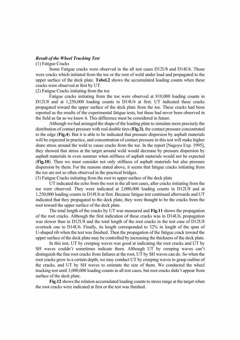
The specimens are full scale models with two main girders, two lateral ribs and four longitudinal U-shaped ribs (Fig.1). Length of U-shaped ribs is 2,500mm and it is Japanese standard in size of the section. Steel quality of material is SM490. These specimens have no asphalt layer. Structural parameters are thickness of deck plate and U-shaped rib. One specimen has deck plate of the thickness of 12mm and another has 14mm, both of them have two U-shaped ribs of the thickness of 6mm and 8mm. Then combination of thickness of deck plate and U-shaped rib is four varieties. In Japan, we usually use plates of 12mm thickness for deck plate. We tried to confirm effect of increasing their thickness.
We adopted carbon dioxide arc welding by a self-propelled welding machine for welding of U-shaped ribs and deck plate and we confirmed penetration size was over 75% of 1 Japan Bridge Association (Yokogawa-Bridge Corporation)
thickness of U-shaped rib by weldability test. Experimental Conditions
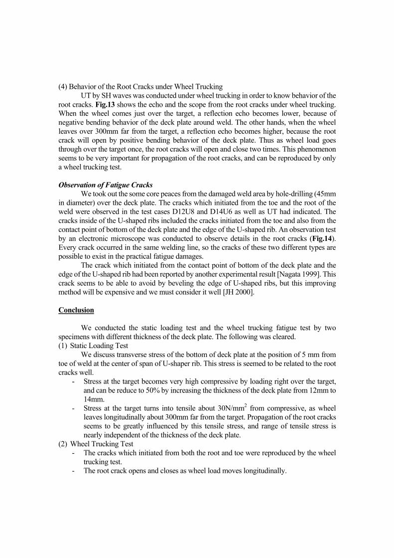
Experimental studies consist of the static loading test and wheel trucking fatigue test. Tabel.1 shows the experimental programs. The static loading test was conducted in all four cases in order to confirm influence of thickness of deck plate or U-shaped rib. The wheel trucking test was conducted in two cases (D12U8, D14U6) which were most contrastive for combination of thickness. Experimental studies were conducted by the wheel trucking machine (Fig.2). Load was 118kN because steel materials were not yielded and the axis load of over 280kN had been often measured in Japan. Static Loading Test Shape of the Loading Plate
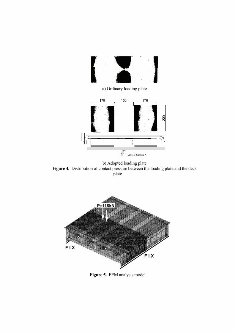
Shape of loading plate is very important, because deck plate and U-shaped rib support load directly and contact pressure between deck plate and loading plate depends on the shape of loading plate. We decided shape and size of the loading plate in consideration of the following points,
a) Distribution of contact pressure by the rear double tires of the large vehicle without asphalt pavement.
b) Fitting the result of FEM analysis and result of the static loading test. Ordinarily, we use the other loading plates which consists of two steel plates
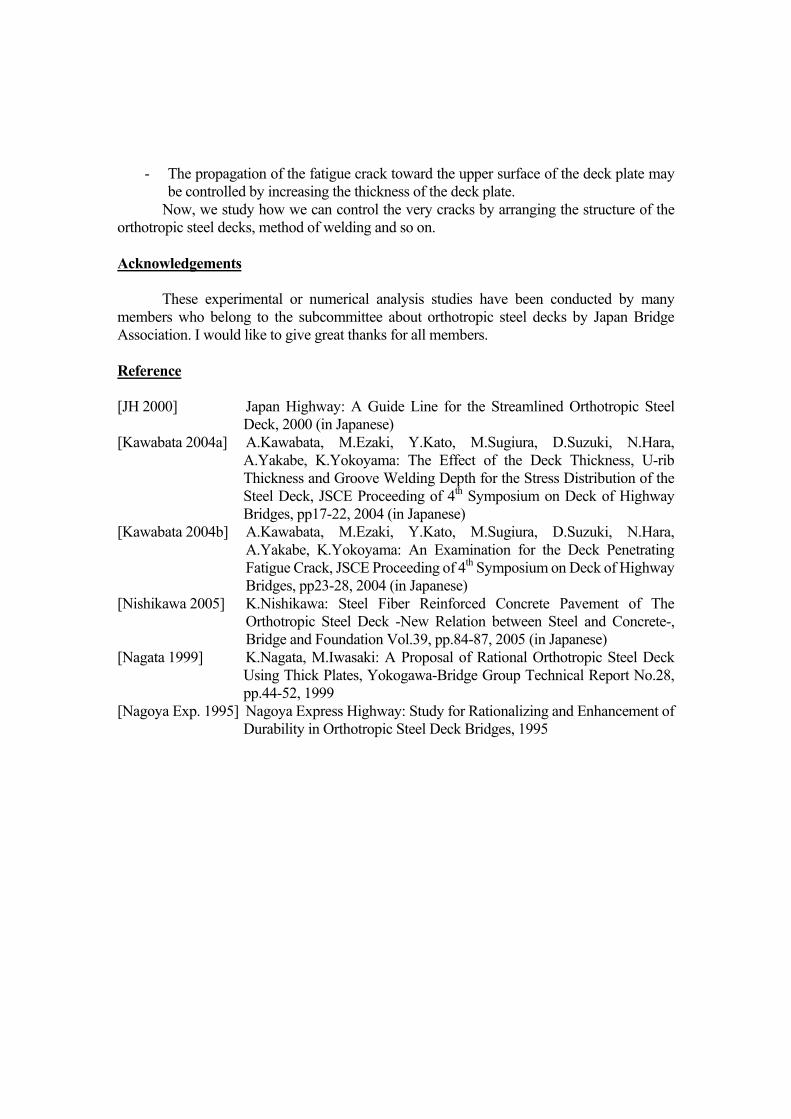
connected each other by the shearing key. But partial deformation in the deck plate may make stress concentration around edge of contact area when ordinal loading plates are adopted for orthotropic steel deck. Therefore we installed two urethanes sheets (200mm x 175mm) at 150mm space in lowest layer in order to simulate the rear double tires (Fig.3). Fig.4 shows distribution of contact pressure when load is at work over weld of deck plate and U-shaped rib. No stress concentration appears around center of the loading area with the adopted loading plate as well as the real double tires. We also confirmed that stress distribution was almost equal to result of FEM analysis. Method of the Static Loading Test
Steel wheel gave vertical static load through the above loading plate in the static loading test. Static load was given to wide area over the deck plate surface so that influence lines could be made. The strain gage is 3mm in length, and these were attached at 5mm from toe of weld. FEM Analysis
FEM analysis for 3D model of the specimen was conducted before the static loading test. Fig.5 shows the analysis model. This model consists of shell elements. We evaluated validity of experimental results by results of FEM analysis. Results of Static Loading Test
Displacement of Deck Plate Fig.6 shows the transverse influence line of vertical displacement of deck plate and
U-shaped ribs in the specimen (T12) with the deck plate of 12mm thickness. We can see equality of results experiment and FEM analysis. Stress around Weld of Deck Plate and U-shaped Rib
In this paper, we discuss transverse stress of the bottom of deck plate at the position of 5 mm from toe of weld at the center of span of U-shaper rib. We had confirmed close correlation of stress of the target and the root of weld.
Fig.7 shows the transverse influence line of the target stress in specimen T12. Loading right above the target causes the maximum compressive stress -266.8N/mm2. Fig.8 shows the transverse influence line of the target stress in specimens T12 and T14. Although a maximum compressive stress was -238.6N/mm2 in T12, but increasing the thickness of deck plate from 12mm to 14mm reduces this maximum stress to 50%. Fig.9 shows the longitudinal influence line of the target stress in the test cases D12U8 and D14U6. We can see the following.
- High compressive stress suddenly decreases as the wheel load leaves in longitudinal direction from the target.
- When the wheel load leaves over 300mm far in longitudinal direction from the target, compressive stress changes into a tensile stress about 30N/mm2.
- Tensile stress is independent of thickness of the deck plate. This tensile stress is similar to superposed stress which occurs by the tandem wheels
like large vehicle’s rear wheels, and it depends on deformation of the deck plate as a beam [Kawabata 2004b]. Only compressive stress occurs at the target by a fatigue test in a fix point, therefore this alternating stress may be reproducible by only a wheel trucking test where the load moves longitudinally. Wheel Trucking Test Aim and Method of Test
We conducted the wheel trucking fatigue test in order to reproduce the fatigue crack which propagated to upper surface of the deck plate from the root of the weld and confirm influence of increasing the deck plate thickness. The test cases were D12U8 and D14U6 (Tabel.1).
The wheel trucking machine is same as one used in the static loading test. Load was 118kN, and we used thirteen loading plates (Fig.3) in longitudinal on the deck plate, total loading line was 2,000mm long. The loading position was just over the weld of U-shaped rib and deck plate where the maximum compressive stress occurred around the target in consideration of result of the static test. Loading speed was 15 rpm. Ultrasonic Test (UT) for Fatigue Damages
We conducted UT by creeping waves, the SH waves and 70 degree angle beam every 300,000 loading counts, and we checked the root cracks and their propagation. We grasped outline of the cracks by creeping waves, and judged presence of cracks by the SH waves, and identified the position of cracks by 70 degree angle beam.
Result of the Wheel Trucking Test (1) Fatigue Cracks
Some Fatigue cracks were observed in the all test cases D12U8 and D14U6. Those were cracks which initiated from the toe or the root of weld under load and propagated to the upper surface of the deck plate. Tabel.2 shows the accumulated loading counts when these cracks were observed at first by UT. (2) Fatigue Cracks initiating from the toe
Fatigue cracks initiating from the toe were observed at 810,000 loading counts in D12U8 and at 1,250,000 loading counts in D14U6 at first. UT indicated these cracks propagated toward the upper surface of the deck plate from the toe. These cracks had been reported as the results of the experimental fatigue tests, but these had never been observed in the field as far as we knew it. This difference must be considered in future.
Although we had arranged the shape of the loading plate to simulate more precisely the distribution of contact pressure with real double tires (Fig.3), the contact pressure concentrated to the edge (Fig.4). But it is able to be indicated that pressure dispersion by asphalt materials will be expected in practice, and concentration of contact pressure in this test will make higher share stress around the weld to cause cracks from the toe. In the report [Nagoya Exp. 1995], they showed that stress at the target around weld would decrease by pressure dispersion by asphalt materials in even summer when stiffness of asphalt materials would not be expected (Fig.10). Then we must consider not only stiffness of asphalt materials but also pressure dispersion by them. For the reasons stated above, it seems that fatigue cracks initiating from the toe are not so often observed in the practical bridges. (3) Fatigue Cracks initiating from the root to upper surface of the deck plate
UT indicated the echo from the root in the all test cases, after cracks initiating from the toe were observed. They were indicated at 2,000,000 loading counts in D12U8 and at 1,250,000 loading counts in D14U6 at first. Because fatigue test continued afterwards and UT indicated that they propagated to the deck plate, they were thought to be the cracks from the root toward the upper surface of the deck plate.
The total length of the cracks by UT was measured and Fig.11 shows the propagation of the root cracks. Although the first indication of these cracks was in D14U6, propagation was slower than in D12U8 and the total length of the root cracks in the test case of D12U8 overtook one in D14U6. Finally, its length corresponded to 32% in length of the span of U-shaped rib when the test was finished. Then the propagation of the fatigue crack toward the upper surface of the deck plate may be controlled by increasing the thickness of the deck plate.
In this test, UT by creeping waves was good at indicating the root cracks and UT by SH waves couldn’t sometimes indicate them. Although UT by creeping waves can’t distinguish the fine root cracks from failures at the root, UT by SH waves can do. So when the root cracks grow to a certain depth, we may conduct UT by creeping waves to grasp outline of the cracks, and UT by SH waves to estimate the size of them. We conducted the wheel trucking test until 3,000,000 loading counts in all test cases, but root cracks didn’t appear from surface of the deck plate.
Fig.12 shows the relation accumulated loading counts to stress range at the target when the root cracks were indicated at first or the test was finished.
(4) Behavior of the Root Cracks under Wheel Trucking UT by SH waves was conducted under wheel trucking in order to know behavior of the
root cracks. Fig.13 shows the echo and the scope from the root cracks under wheel trucking. When the wheel comes just over the target, a reflection echo becomes lower, because of negative bending behavior of the deck plate around weld. The other hands, when the wheel leaves over 300mm far from the target, a reflection echo becomes higher, because the root crack will open by positive bending behavior of the deck plate. Thus as wheel load goes through over the target once, the root cracks will open and close two times. This phenomenon seems to be very important for propagation of the root cracks, and can be reproduced by only a wheel trucking test.
Observation of Fatigue Cracks
We took out the some core peaces from the damaged weld area by hole-drilling (45mm in diameter) over the deck plate. The cracks which initiated from the toe and the root of the weld were observed in the test cases D12U8 and D14U6 as well as UT had indicated. The cracks inside of the U-shaped ribs included the cracks initiated from the toe and also from the contact point of bottom of the deck plate and the edge of the U-shaped rib. An observation test by an electronic microscope was conducted to observe details in the root cracks (Fig.14). Every crack occurred in the same welding line, so the cracks of these two different types are possible to exist in the practical fatigue damages.
The crack which initiated from the contact point of bottom of the deck plate and the edge of the U-shaped rib had been reported by another experimental result [Nagata 1999]. This crack seems to be able to avoid by beveling the edge of U-shaped ribs, but this improving method will be expensive and we must consider it well [JH 2000]. Conclusion
We conducted the static loading test and the wheel trucking fatigue test by two specimens with different thickness of the deck plate. The following was cleared. (1) Static Loading Test
We discuss transverse stress of the bottom of deck plate at the position of 5 mm from toe of weld at the center of span of U-shaper rib. This stress is seemed to be related to the root cracks well.
- Stress at the target becomes very high compressive by loading right over the target, and can be reduce to 50% by increasing the thickness of the deck plate from 12mm to 14mm.
- Stress at the target turns into tensile about 30N/mm2 from compressive, as wheel leaves longitudinally about 300mm far from the target. Propagation of the root cracks seems to be greatly influenced by this tensile stress, and range of tensile stress is nearly independent of the thickness of the deck plate.
(2) Wheel Trucking Test - The cracks which initiated from both the root and toe were reproduced by the wheel
trucking test. - The root crack opens and closes as wheel load moves longitudinally.
- The propagation of the fatigue crack toward the upper surface of the deck plate may be controlled by increasing the thickness of the deck plate.
Now, we study how we can control the very cracks by arranging the structure of the orthotropic steel decks, method of welding and so on. Acknowledgements
These experimental or numerical analysis studies have been conducted by many
members who belong to the subcommittee about orthotropic steel decks by Japan Bridge Association. I would like to give great thanks for all members. Reference [JH 2000] Japan Highway: A Guide Line for the Streamlined Orthotropic Steel
Deck, 2000 (in Japanese) [Kawabata 2004a] A.Kawabata, M.Ezaki, Y.Kato, M.Sugiura, D.Suzuki, N.Hara,
A.Yakabe, K.Yokoyama: The Effect of the Deck Thickness, U-rib Thickness and Groove Welding Depth for the Stress Distribution of the Steel Deck, JSCE Proceeding of 4th Symposium on Deck of Highway Bridges, pp17-22, 2004 (in Japanese)
[Kawabata 2004b] A.Kawabata, M.Ezaki, Y.Kato, M.Sugiura, D.Suzuki, N.Hara, A.Yakabe, K.Yokoyama: An Examination for the Deck Penetrating Fatigue Crack, JSCE Proceeding of 4th Symposium on Deck of Highway Bridges, pp23-28, 2004 (in Japanese)
[Nishikawa 2005] K.Nishikawa: Steel Fiber Reinforced Concrete Pavement of The Orthotropic Steel Deck -New Relation between Steel and Concrete-, Bridge and Foundation Vol.39, pp.84-87, 2005 (in Japanese)
[Nagata 1999] K.Nagata, M.Iwasaki: A Proposal of Rational Orthotropic Steel Deck Using Thick Plates, Yokogawa-Bridge Group Technical Report No.28, pp.44-52, 1999
[Nagoya Exp. 1995] Nagoya Express Highway: Study for Rationalizing and Enhancement of Durability in Orthotropic Steel Deck Bridges, 1995
Figure 1. Structural parameters of the specimens
Table 1. Experimental test programs
Load(kN)
Name of Dynamic Test D12U8 D14U6
Thickness of Deck Plate(mm)
12 14
thickness of Trough Rib(mm)
6 8 6 8 8 6
12 14
Static Test Wheel Trucking Test
118 118---
Figure 2. Wheel trucking machine (IHI) Figure 3. Loading plate
a) Ordinary loading plate
b) Adopted loading plate Figure 4. Distribution of contact pressure between the loading plate and the deck
plate
Figure 5. FEM analysis model
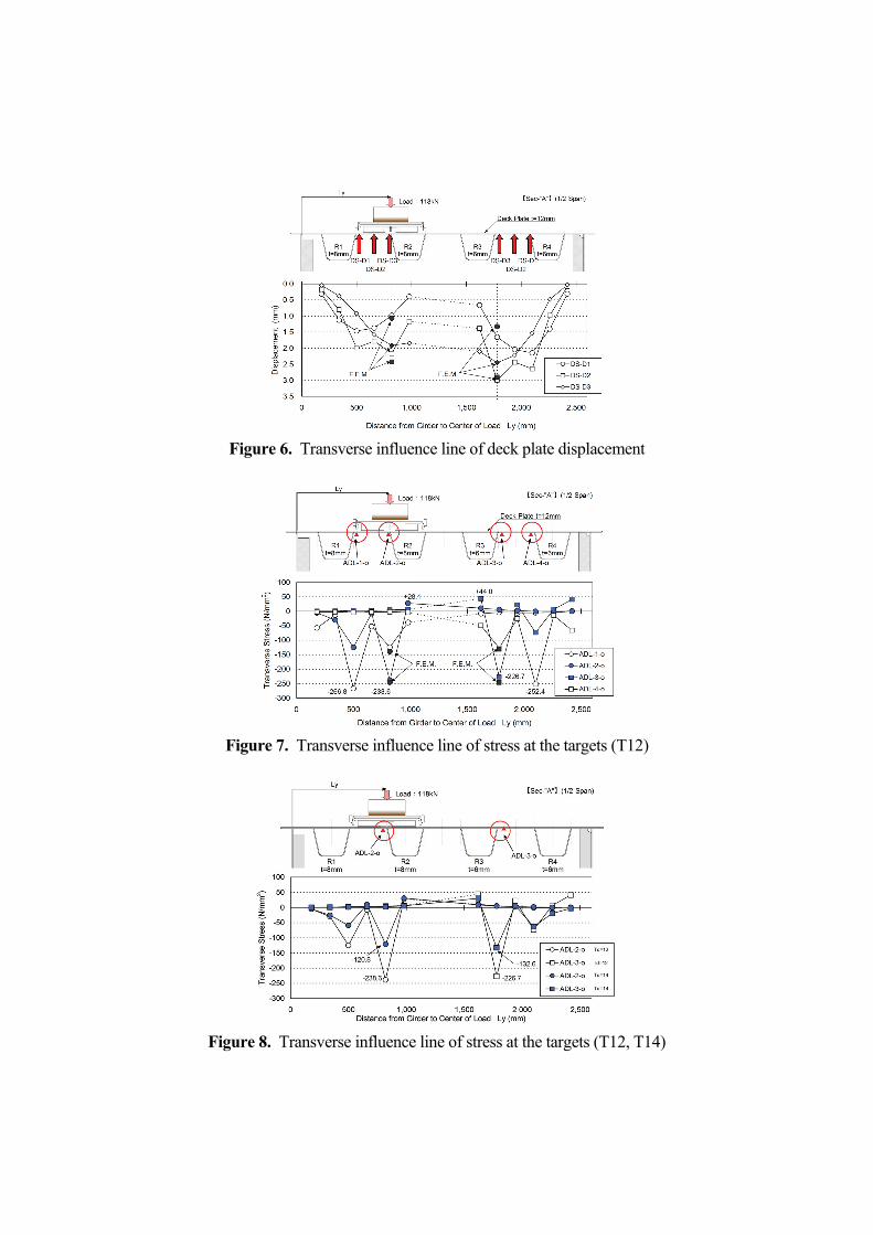
Figure 6. Transverse influence line of deck plate displacement
Figure 7. Transverse influence line of stress at the targets (T12)
Figure 8. Transverse influence line of stress at the targets (T12, T14)
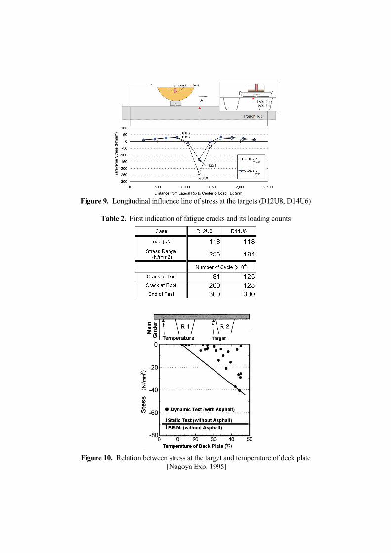
Figure 9. Longitudinal influence line of stress at the targets (D12U8, D14U6)
Table 2. First indication of fatigue cracks and its loading counts
Figure 10. Relation between stress at the target and temperature of deck plate
[Nagoya Exp. 1995]
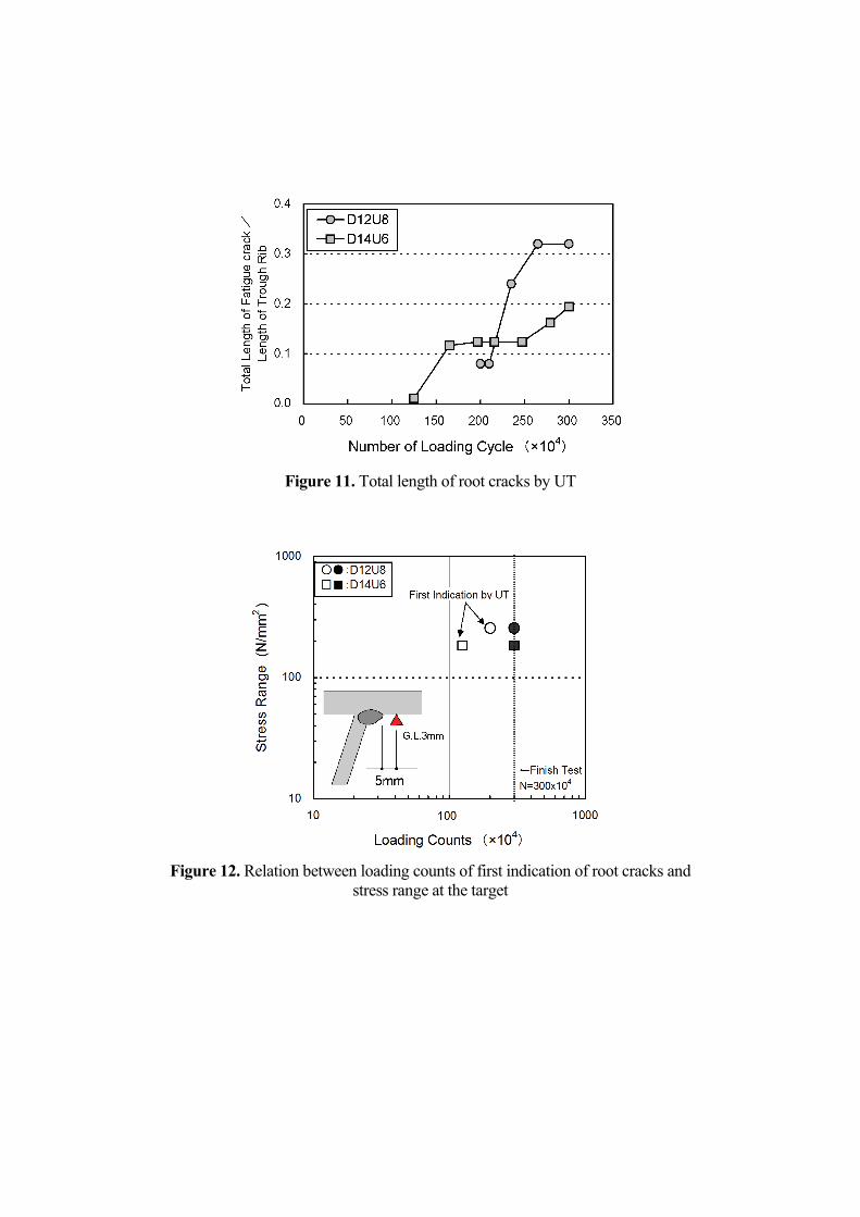
Figure 11. Total length of root cracks by UT
Figure 12. Relation between loading counts of first indication of root cracks and
stress range at the target

Figure 13. Reflection root echo of UT by SH waves under wheel trucking
a) Crack from contact point b) Crack from root of the weld
Figure 14. Photographs of fatigue cracks by an electronic microscope


![TRUCKING INDUSTRY · [ 6 ] TRUCKING INDUSTRY ENVIRONMENTAL BEST PRACTICE GUIDE ThE AUSTRALIAN TRUCKING ASSOCIATION The Australian Trucking Association (ATA) is the national peak body](https://static.fdocuments.net/doc/165x107/5e6e335355a7c4346213f0b4/trucking-6-trucking-industry-environmental-best-practice-guide-the-australian.jpg)