wheel impect test.pdf
4
© Copyright by International OCSCO World Press. All rights reserved. 2008 VOLUME 28 ISSUE 2 June 2008 Short paper 167 of Achievements in Materials and Manufacturing Engineering of Achievements in Materials and Manufacturing Engineering Finite element simulation of wheel impact test C.L. Chang*, S.H. Yang Mechanical Engineering Department, National Yunlin University of Science and Technology, Yunlin, 640, Taiwan, R.O.C. * Corresponding author: E-mail address: [email protected] Received 28.02.2008; published in revised form 01.06.2008 Analysis and modelling AbstrAct Purpose: In order to achieve better performance and quality, the wheel design and manufacturing use a number of wheel tests (rotating bending test, radial fatigue test, and impact test) to insure that the wheel meets the safety requirements. The test is very time consuming and expensive. Computer simulation of these tests can significantly reduce the time and cost required to perform a wheel design. In this study, nonlinear dynamic finite element is used to simulate the SAE wheel impact test. Design/methodology/approach: The test fixture used for the impact test consists of a striker with specified weight. The test is intended to simulate actual vehicle impact conditions. The tire-wheel assembly is mounted at 13° angle to the vertical plane with the edge of the weight in line with outer radius of the rim. The striker is dropped from a specified height above the highest point of the tire-wheel assembly and contacts the outboard flange of the wheel.Because of the irregular geometry of the wheel, the finite element model of an aluminium wheel is constructed by tetrahedral element. A mesh convergence study is carried out to ensure the convergence of the mesh model. The striker is assumed to be rigid elements. Initially, the striker contacts the highest area of the wheel, and the initial velocity of the striker is calculated from the impact height. The simulated strains at two locations on the disc are verified by experimental measurements by strain gages. The damage parameter of a wheel during the impact test is a strain energy density from the calculated result. Findings: The prediction of a wheel failure at impact is based on the condition that fracture will occur if the maximum strain energy density of the wheel during the impact test exceeds the total plastic work of the wheel material from tensile test. The simulated results in this work show that the total plastic work can be effectively employed as a fracture criterion to predict a wheel fracture of forged aluminum wheel during impact test. Research limitations/implications: A standard impact load is used to carry out the test. For future study, a heavier striker or higher impact can be used to perform the test in order to produce the rupture at impact. Originality/value: In this study, the nonlinear dynamic finite element analysis is performed to simulate a forged aluminium wheel during SAE impact test. The structural damage parameter of the wheel is estimated by the strain energy density, and the fracture criterion is based on the total plastic work of the wheel material. Computer simulation of wheel impact test can significantly reduce the time and cost required to finalize a wheel design. Keywords: Computational mechanics; Nonlinear dynamic finite element; Total plastic work; Wheel impact test The wheel being critical component in the vehicle has to meet strict requirements of driving safety. The wheel design must meet both the styling appearance and engineering functions. The wheel also must be durable enough to withstand rough loads and harsh environments. Wheel weight and manufacturing cost should be minimized without contradicting the safety requirements. The wheel design and development use three main wheel tests (rotating bending test, radial fatigue test, and impact test) to test a prototype wheel for various fatigue and durability considerations[1,2]. 1. Introduction
description
wheel impact test stress analysis
Transcript of wheel impect test.pdf

© Copyright by International OCSCO World Press. All rights reserved. 2008
VOLUME 28
ISSUE 2
June
2008
Short paper 167
of Achievements in Materialsand Manufacturing Engineeringof Achievements in Materialsand Manufacturing Engineering
Finite element simulation of wheel impact test
C.L. Chang*, S.H. Yang Mechanical Engineering Department, National Yunlin University of Science and Technology, Yunlin, 640, Taiwan, R.O.C.* Corresponding author: E-mail address: [email protected]
Received 28.02.2008; published in revised form 01.06.2008
Analysis and modelling
AbstrActPurpose: In order to achieve better performance and quality, the wheel design and manufacturing use a number of wheel tests (rotating bending test, radial fatigue test, and impact test) to insure that the wheel meets the safety requirements. The test is very time consuming and expensive. Computer simulation of these tests can significantly reduce the time and cost required to perform a wheel design. In this study, nonlinear dynamic finite element is used to simulate the SAE wheel impact test.Design/methodology/approach: The test fixture used for the impact test consists of a striker with specified weight. The test is intended to simulate actual vehicle impact conditions. The tire-wheel assembly is mounted at 13° angle to the vertical plane with the edge of the weight in line with outer radius of the rim. The striker is dropped from a specified height above the highest point of the tire-wheel assembly and contacts the outboard flange of the wheel.Because of the irregular geometry of the wheel, the finite element model of an aluminium wheel is constructed by tetrahedral element. A mesh convergence study is carried out to ensure the convergence of the mesh model. The striker is assumed to be rigid elements. Initially, the striker contacts the highest area of the wheel, and the initial velocity of the striker is calculated from the impact height. The simulated strains at two locations on the disc are verified by experimental measurements by strain gages. The damage parameter of a wheel during the impact test is a strain energy density from the calculated result.Findings: The prediction of a wheel failure at impact is based on the condition that fracture will occur if the maximum strain energy density of the wheel during the impact test exceeds the total plastic work of the wheel material from tensile test. The simulated results in this work show that the total plastic work can be effectively employed as a fracture criterion to predict a wheel fracture of forged aluminum wheel during impact test.Research limitations/implications: A standard impact load is used to carry out the test. For future study, a heavier striker or higher impact can be used to perform the test in order to produce the rupture at impact.Originality/value: In this study, the nonlinear dynamic finite element analysis is performed to simulate a forged aluminium wheel during SAE impact test. The structural damage parameter of the wheel is estimated by the strain energy density, and the fracture criterion is based on the total plastic work of the wheel material. Computer simulation of wheel impact test can significantly reduce the time and cost required to finalize a wheel design.Keywords: Computational mechanics; Nonlinear dynamic finite element; Total plastic work; Wheel impact test
1. Introduction The wheel being critical component in the vehicle has to meet
strict requirements of driving safety. The wheel design must meet both the styling appearance and engineering functions. The wheel
also must be durable enough to withstand rough loads and harsh environments. Wheel weight and manufacturing cost should be minimized without contradicting the safety requirements. The wheel design and development use three main wheel tests (rotating bending test, radial fatigue test, and impact test) to test a prototype wheel for various fatigue and durability considerations[1,2].
1.Introduction

Short paper168
Journal of Achievements in Materials and Manufacturing Engineering
C.L. Chang, S.H. Yang
Volume 28 Issue 2 June 2008
The rotating bending test simulates cornering induced loads by applying a constant rotating bending moment to the wheel. In the radial fatigue test, the wheel and tire assembly is loaded radially against a constantly rotating drum. The impact test is established to evaluate the impact characteristics of passenger car wheels.
The time to test and inspect wheel during production is very consuming. For economic reasons, it is important to reduce the time spending in trial and error during the development and testing phase of wheel. Computer simulation of wheel tests can significantly reduce the time and cost required to finalize a wheel design. The simulation of rotating bending test and radial fatigue test have shown good agreement with experimental results[3-5]. Riesner et. al.[6] employed three step analysis to simulate the impact test: static, dynamic, and fracture mechanics. A static finite element simulation is carried out to obtain an effective spring constant of wheel. Then a simple model consisting of lumped masses, springs, and dampers is performed to simulation the dynamic response. In the third step, the peak force acquired the dynamic response is applied to the finite element model to calculate the stress and strain energy density. The total plastic work is utilized as a damage criterion to predict a wheel failure. In this study, the nonlinear dynamic finite element analysis is performed to simulate a forged aluminium wheel during SAE impact test. The strain, stress, and strain energy density distribution are obtained from finite element results. The structural damage parameter of the wheel is estimated by the strain energy density, and the fracture criterion is based on the total plastic work of the wheel material.
2. Modeling for impact test
2.1. Test fixture The test fixture used for the test, is show in Fig. 1. It consists,
of a striker of 476 kg with 375 mm length, 125 width, and 126.94 mm height. The tire-wheel assembly is mounted at 13° angle to the horizontal plane with the lower edge of the striker in line with the outer bead radius of the rim. The striker is dropped from a height of 230±2 mm above the highest point of the tire-wheel assembly.
In order to pass the impact test, a wheel must meet the following minimum performance standards [2]: No visible fracture of the central member of the wheel assembly. No separation of the central member from the rim. No sudden loss of tire air pressure. Deformation of the wheel assembly, or fracture in the area of
the rim section contracted by the faceplate weight system do not constitute a failure.
2.2. Finite element model
The diameter of the tested wheel is 17 inch. Due to the symmetry of the geometry, loading, and boundary conditions, only one half of the wheel is modeled. The mesh model is constructed by free mesh, because of the irregular geometry of the wheel. The wheel is built with tetrahedral elements. The striker and support are created with hexahedral elements. Symmetric constraints are imposed on the symmetric plane of the structure.
Fig. 1. Fixture for wheel impact test
The nodes at the contacted surface between the wheel and support are constrained to move together. The striker is modeled as a rigid body. The displacement of striker is constrained to move in vertical direction. In addition, the bottom surface of support is fixed to prevent the rigid body motion. The finite element model for wheel impact test is shown in Fig. 2, where the mesh size of the wheel is 6 mm. The mesh model data in Fig. 2 are shown in Table 1.
Fig. 2. Finite element model for impact test
Table 1. Mesh model data
Material Element Type Element Number Striker Steel Hexahedral Ele. 324
Wheel Aluminium 6061-T6 Tetrahedral Ele. 68027
Support Steel Hexahedral Ele. 908 Cushion Rubber Hexahedral Ele. 960
Z
Y
X
striker
wheel
rubber
support
13
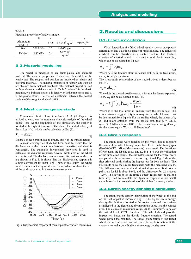
Table 2. Materials properties of analysis model
E t Aluminum 6061-T6 - 0.33 2.7×10³ kg/m3 219.2 p
0.051
Steel 206.9GPa 0.3 8×10⁴ kg/m3 -
Rubber 1.82MPa 0.4 8.97×10² kg/m3 -
2.3. Material modelling
The wheel is modelled as an elasto-plastic and isotropic material. The material properties of wheel are obtained from the tensile test. The support and cushion are modelled as elastic and isotropic materials. The material properties of support and cushion are obtained from material handbook. The material properties used in finite element model are shown in Table 2, where E is the elastic modulus, is Poisson’s ratio, is density, t is the true stress, and p is the plastic strain. The friction coefficient between the contact surface of the weight and wheel is 0.3. 2.4. Mesh convergence study
Commercial finite element software ABAQUS/Explicit is
utilized to carry out the nonlinear dynamic analysis of the wheel impact test. At the beginning of the simulation, the striker is located at the highest location of the wheel. The initial velocity of the striker is V0, which can be calculate by Eq. (1).
ghV 20 (1) Where g is acceleration due to gravity and h is the impact height.
A mesh convergence study has been done to ensure that the displacement at the contact point between the striker and wheel is convergent. The automatic incremental time step is used to calculate the dynamic response. Several mesh sizes of the wheel are performed. The displacement responses for various mesh sizes are shown in Fig. 3. It shows that the displacement response is almost convergent for mesh size 7 mm. In this study, the wheel model is constructed by mesh size 6 mm, which is about the size of the strain gage used in the strain measurement.
0.00 0.01 0.02 0.03 0.04 0.05 0.06-45-40-35-30-25-20-15-10-505
Dis
plac
emen
t (m
m)
Time (s)
10mm 8mm 7mm 6mm
Fig. 3. Displacement response at contact point for various mesh sizes
3. Results and discussions 3.1. Fracture criterion
Visual inspection of a failed wheel usually shows some plastic deformation and a distinct surface of rapid fracture. The failure of a wheel can be classified as a ductile fracture. The fracture criterion of a tested wheel is base on the total plastic work Wp, which can be calculated as Eq. (2).
ptp df
0w
(2) Where f is the fracture strain in tensile test, t is the true stress, and p is the plastic strain. The stress-strain relationship of the studied wheel is described as Eq. (3).
npt k
(3) Where k is the strength coefficient and n is strain hardening exponent. Then, Wp can be calculated by Eq. (4).
f
ndk ff
pn
pp 0 1w
(4) Where f is the true stress at fracture from the tensile test. The critical strain energy density necessary for the wheel fracture can be determined from Eq. (4). For the studied wheel, the values of f,
f, and n are obtained from the tensile test, that f = 0.131, f = 330.6 MPa, and n = 0.051. The critical strain energy density
for the wheel equals Wp = 41.21 Nmm/mm3. 3.2. Strain response
The strain gages were attached on the wheel disc to measure
the strain of the wheel during impact test. Two rosette strain gages (EA-06-060R2, Micro-Measurements) were used. The locations of two gages are labeled as L1 and L2 in Fig. 4. For the validation of the simulation results, the estimated strains for the wheel were compared with the measured strains. Fig. 5 and Fig. 6 show the first principal strain during the impact test for both methods. The FE results show the similar tendencies with the measured strains. The difference of measured and estimated maximum first prince-pal strain for L1 is about 9.9%, and the difference for L2 is about 10.6%. The deviation of the finite element result may be that the time step used to calculate the dynamic response is not small enough to take into consideration of the higher frequency modes.
3.3 Strain energy density distribution
The strain energy density distribution of the wheel at the end
of the first impact is shown in Fig. 7. The higher strain energy density distribution is located at the contact area and disc surface as indicated in the figure, and the maximum value is at the contact area. The estimated maximum value, 28.46 Nmm/mm3, is below the critical level, 42.21 Nmm/mm3. The wheel should pass the impact test based on the ductile fracture criterion. The tested wheel passed the real test. The visual examination of the tested wheel showed no crack and obvious plastic deformation at the contact area and around higher strain energy density area.
2.Modelingforimpacttest
2.1.testfixture
2.2.Finiteelementmodel
169
Analysis and modelling
Finite element simulation of wheel impact test
The rotating bending test simulates cornering induced loads by applying a constant rotating bending moment to the wheel. In the radial fatigue test, the wheel and tire assembly is loaded radially against a constantly rotating drum. The impact test is established to evaluate the impact characteristics of passenger car wheels.
The time to test and inspect wheel during production is very consuming. For economic reasons, it is important to reduce the time spending in trial and error during the development and testing phase of wheel. Computer simulation of wheel tests can significantly reduce the time and cost required to finalize a wheel design. The simulation of rotating bending test and radial fatigue test have shown good agreement with experimental results[3-5]. Riesner et. al.[6] employed three step analysis to simulate the impact test: static, dynamic, and fracture mechanics. A static finite element simulation is carried out to obtain an effective spring constant of wheel. Then a simple model consisting of lumped masses, springs, and dampers is performed to simulation the dynamic response. In the third step, the peak force acquired the dynamic response is applied to the finite element model to calculate the stress and strain energy density. The total plastic work is utilized as a damage criterion to predict a wheel failure. In this study, the nonlinear dynamic finite element analysis is performed to simulate a forged aluminium wheel during SAE impact test. The strain, stress, and strain energy density distribution are obtained from finite element results. The structural damage parameter of the wheel is estimated by the strain energy density, and the fracture criterion is based on the total plastic work of the wheel material.
2. Modeling for impact test
2.1. Test fixture The test fixture used for the test, is show in Fig. 1. It consists,
of a striker of 476 kg with 375 mm length, 125 width, and 126.94 mm height. The tire-wheel assembly is mounted at 13° angle to the horizontal plane with the lower edge of the striker in line with the outer bead radius of the rim. The striker is dropped from a height of 230±2 mm above the highest point of the tire-wheel assembly.
In order to pass the impact test, a wheel must meet the following minimum performance standards [2]: No visible fracture of the central member of the wheel assembly. No separation of the central member from the rim. No sudden loss of tire air pressure. Deformation of the wheel assembly, or fracture in the area of
the rim section contracted by the faceplate weight system do not constitute a failure.
2.2. Finite element model
The diameter of the tested wheel is 17 inch. Due to the symmetry of the geometry, loading, and boundary conditions, only one half of the wheel is modeled. The mesh model is constructed by free mesh, because of the irregular geometry of the wheel. The wheel is built with tetrahedral elements. The striker and support are created with hexahedral elements. Symmetric constraints are imposed on the symmetric plane of the structure.
Fig. 1. Fixture for wheel impact test
The nodes at the contacted surface between the wheel and support are constrained to move together. The striker is modeled as a rigid body. The displacement of striker is constrained to move in vertical direction. In addition, the bottom surface of support is fixed to prevent the rigid body motion. The finite element model for wheel impact test is shown in Fig. 2, where the mesh size of the wheel is 6 mm. The mesh model data in Fig. 2 are shown in Table 1.
Fig. 2. Finite element model for impact test
Table 1. Mesh model data
Material Element Type Element Number Striker Steel Hexahedral Ele. 324
Wheel Aluminium 6061-T6 Tetrahedral Ele. 68027
Support Steel Hexahedral Ele. 908 Cushion Rubber Hexahedral Ele. 960
Z
Y
X
striker
wheel
rubber
support
13
Table 2. Materials properties of analysis model
E t Aluminum 6061-T6 - 0.33 2.7×10³ kg/m3 219.2 p
0.051
Steel 206.9GPa 0.3 8×10⁴ kg/m3 -
Rubber 1.82MPa 0.4 8.97×10² kg/m3 -
2.3. Material modelling
The wheel is modelled as an elasto-plastic and isotropic material. The material properties of wheel are obtained from the tensile test. The support and cushion are modelled as elastic and isotropic materials. The material properties of support and cushion are obtained from material handbook. The material properties used in finite element model are shown in Table 2, where E is the elastic modulus, is Poisson’s ratio, is density, t is the true stress, and p is the plastic strain. The friction coefficient between the contact surface of the weight and wheel is 0.3. 2.4. Mesh convergence study
Commercial finite element software ABAQUS/Explicit is
utilized to carry out the nonlinear dynamic analysis of the wheel impact test. At the beginning of the simulation, the striker is located at the highest location of the wheel. The initial velocity of the striker is V0, which can be calculate by Eq. (1).
ghV 20 (1) Where g is acceleration due to gravity and h is the impact height.
A mesh convergence study has been done to ensure that the displacement at the contact point between the striker and wheel is convergent. The automatic incremental time step is used to calculate the dynamic response. Several mesh sizes of the wheel are performed. The displacement responses for various mesh sizes are shown in Fig. 3. It shows that the displacement response is almost convergent for mesh size 7 mm. In this study, the wheel model is constructed by mesh size 6 mm, which is about the size of the strain gage used in the strain measurement.
0.00 0.01 0.02 0.03 0.04 0.05 0.06-45-40-35-30-25-20-15-10-505
Dis
plac
emen
t (m
m)
Time (s)
10mm 8mm 7mm 6mm
Fig. 3. Displacement response at contact point for various mesh sizes
3. Results and discussions 3.1. Fracture criterion
Visual inspection of a failed wheel usually shows some plastic deformation and a distinct surface of rapid fracture. The failure of a wheel can be classified as a ductile fracture. The fracture criterion of a tested wheel is base on the total plastic work Wp, which can be calculated as Eq. (2).
ptp df
0w
(2) Where f is the fracture strain in tensile test, t is the true stress, and p is the plastic strain. The stress-strain relationship of the studied wheel is described as Eq. (3).
npt k
(3) Where k is the strength coefficient and n is strain hardening exponent. Then, Wp can be calculated by Eq. (4).
f
ndk ff
pn
pp 0 1w
(4) Where f is the true stress at fracture from the tensile test. The critical strain energy density necessary for the wheel fracture can be determined from Eq. (4). For the studied wheel, the values of f,
f, and n are obtained from the tensile test, that f = 0.131, f = 330.6 MPa, and n = 0.051. The critical strain energy density
for the wheel equals Wp = 41.21 Nmm/mm3. 3.2. Strain response
The strain gages were attached on the wheel disc to measure
the strain of the wheel during impact test. Two rosette strain gages (EA-06-060R2, Micro-Measurements) were used. The locations of two gages are labeled as L1 and L2 in Fig. 4. For the validation of the simulation results, the estimated strains for the wheel were compared with the measured strains. Fig. 5 and Fig. 6 show the first principal strain during the impact test for both methods. The FE results show the similar tendencies with the measured strains. The difference of measured and estimated maximum first prince-pal strain for L1 is about 9.9%, and the difference for L2 is about 10.6%. The deviation of the finite element result may be that the time step used to calculate the dynamic response is not small enough to take into consideration of the higher frequency modes.
3.3 Strain energy density distribution
The strain energy density distribution of the wheel at the end
of the first impact is shown in Fig. 7. The higher strain energy density distribution is located at the contact area and disc surface as indicated in the figure, and the maximum value is at the contact area. The estimated maximum value, 28.46 Nmm/mm3, is below the critical level, 42.21 Nmm/mm3. The wheel should pass the impact test based on the ductile fracture criterion. The tested wheel passed the real test. The visual examination of the tested wheel showed no crack and obvious plastic deformation at the contact area and around higher strain energy density area.
3.resultsanddiscussions
2.3.Materialmodelling
2.4.Meshconvergencestudy
3.1.Fracturecriterion
3.2.strainresponse
3.3.strainenergydensitydistribution

Short paper170 READING DIRECT: www.journalamme.org
Journal of Achievements in Materials and Manufacturing Engineering Volume 28 Issue 2 June 2008
Fig. 4. Strain gage locations
0.00 0.01 0.02 0.03 0.04 0.05 0.06-0.001
0.000
0.001
0.002
0.003
0.004
0.005
0.006
0.007
Firs
t Prin
cipa
l Stra
in
Time (s)
meas. simu.
Fig. 5. Principal strain response at location one
0.00 0.01 0.02 0.03 0.04 0.05 0.06-0.00020.00000.00020.00040.00060.00080.00100.00120.00140.00160.00180.00200.0022
Firs
t Prin
cipa
l Stra
in
Time (s)
meas. simu.
Fig. 6. Principal strain response at location two
4. Conclusions
The dynamic response of a wheel during the impact test is highly nonlinear. Nonlinear dynamic finite element with a reasonable mesh size and time step can reliably calculate the dynamic response. The dynamic finite element result can be
Fig. 7. Strain energy density distribution of wheel
verified by comparing the calculated strain with the measured strain from the strain gage. The total plastic work of a wheel material, which can be obtained by the material properties from a tensile test, is utilized as a ductile fracture criterion. The prediction of a wheel failure is based on the condition that fracture will occur if the maximum strain energy density exceeds the total plastic work. The simulated results in this work show that the total plastic work can be effectively employed as a fracture criterion to predict a wheel fracture of forged aluminium wheel during impact test.
Acknowledgements This research work has been supported by Super Alloy
Industrial Company, Taiwan. The authors gratefully acknowledge their support.
References [1] SAE Handbook J328, Wheels-passenger car and light truck
performance requirements and test procedures, Society of Automotive Engineers, Inc., Warrendale, 2001.
[2] SAE Handbook J175, Wheels-impact test procedures-road vehicles, Society of Automotive Engineers, Inc., Warrendale, 2001.
[3] H.M. Karandikar, W. Fuchs, Fatigue life prediction for wheels by simulation of the rotating bending test, SAE Technical Paper 900147 (1990) 1-11.
[4] U. Kocabicak, M. Firat, Numerical analysis of wheel cornering, Fatigue tests, Engineering Failure Analysis 8 (2001) 339-354.
[5] M. Riesner, R.I. DeVries, Finite element analysis and structural optimization of vehicle wheels, SAE Technical Paper 830133 (1983) 1-18.
[6] M. Riesner, M.P. Zebrowski, R.J. Gavalier, Computer simulation of wheel impact test, SAE Technical Paper 860829 (1986) 269-275.
L1
L2
references
Acknowledgements
4.conclusions