What software do I need to run a CNC mill? · 1 The premier source of tooling, parts, and...
17
1 The premier source of tooling, parts, and accessories for bench top machinists. What software do I need to run a CNC mill? Creating a part on a CNC mill is a three phase process. The part is drawn in a CAD (Computer Aided Design) drawing program such as AutoCAD. Then a CAM (Computer Aided Manufacturing) program is used to convert the CAD drawing to G-Code. Finally, the G-code controls the CNC mill as it makes the part. We will take a look at what is involved in using these three kinds of software by sketching out the creation of a very simple part. Creating a CAD Drawing There are dozens of CAD programs with which you can create a drawing. Costs vary from free to many thousands of dollars. We are not going to get into reviews or recommendations here, but simply describe the CAD program that we know the best; TurboCAD. Let’s take a look at the steps required to create a drawing. A new drawing in TurboCAD is based on a template. In this case the template defines an A-size (8.5 x 11”) sheet using inches for dimensions and including the title block. This view is the Paper view. This is the page that prints. To work on the drawing we switch to Model view. The title block is gone and a grid appears. This is where we create our drawing.
Transcript of What software do I need to run a CNC mill? · 1 The premier source of tooling, parts, and...

1
The premier source of tooling, parts, and accessories for bench top machinists.
What software do I need to run a CNC mill? Creating a part on a CNC mill is a three phase process. The part is drawn in a CAD (Computer Aided Design) drawing program such as AutoCAD. Then a CAM (Computer Aided Manufacturing) program is used to convert the CAD drawing to G-Code. Finally, the G-code controls the CNC mill as it makes the part.
We will take a look at what is involved in using these three kinds of software by sketching out the creation of a very simple part.
Creating a CAD Drawing There are dozens of CAD programs with which you can create a drawing. Costs vary from free to many thousands of dollars. We are not going to get into reviews or recommendations here, but simply describe the CAD program that we know the best; TurboCAD. Let’s take a look at the steps required to create a drawing.
A new drawing in TurboCAD is based on a template. In this case the template defines an A-size (8.5 x 11”) sheet using inches for dimensions and including the title block.
This view is the Paper view. This is the page that prints. To work on the drawing we switch to Model view. The title block is gone and a grid appears. This is where we create our drawing.

2
To start the drawing of our sample part, use the Rectangle tool on the left side of the drawing area to create a rectangle that is 2.5” tall and 1.5” wide. You can use your mouse to define the corners of the rectangle, but you will quickly find that you need to use the parameter block at the bottom of the screen to enter the values you want if you want your drawing to be accurate. Your finished part will not be any more accurate than your drawing.
Create a double line ¾” long and ¼” wide. Center it ½” above the bottom of the part.
Use the Arc tool to add semi-circles to the ends of the double line. This completes the slot.

3
Add a 1” square centered ¾” below the top of the part. Use the Fillet tool to round the corners to 1/8” radius.
This completes the top view of the part. We need to add this view to a separate layer so that the CAD program can differentiate this view from the other information in this drawing. We create a layer named Top View and assign all the elements of this view to that layer.

4
Now add the right view of the part.
Here’s what the Paper view looks like.

5
To move this file to PartMaster CAM, we save it as a DXF (Drawing eXchange File).
The CAM Process CAM (Computer Aided Manufacturing) software takes the CAD drawing you created and translates it into G-code. It is an interactive process, because you must tell the software what tools you will use, plus information such as spindle speed, cutting depth and cutting speed.
The CAM program we are using is Dolphin PartMaster CAM. Open PartMaster CAM and select Create a new job from a DXF file. Load the Example 1.DXF file we created with TurboCAD.
In the DXF Import Options dialog choose Import only geometery on layer, and enter Top View.

6
The top view of the part appears in PartMaster CAM. Here we have used View > Options to show Geometry Names.

7
In the bar on the right of the screen, click Area Clearance and Pockets. Then click User Defined. The Pocket: Custom Shape dialog appears.
Here we tell the CAD program how to clear the square at the top of the part. We have defined an end mill that is ¼” in diameter and set the spindle speed to 1000 RPM. We will cut to a depth of 0.26” so we go completely through the part in three passes.
Use Execute > Run Program to see how the program will run.
Now click the Command tab on the right side of the window and make the settings for the slot at the bottom of the part.

8
Now the machining parameters for both areas are set. Use Execute > Post Process to create the G-code.
The program trundles for a few seconds, then produces the G-code necessary to run this part.
( Produced :- 19:45:18 Friday, October 23, 2009 ) ( CNC File :- Example 1 ) ( Post Processor :- M_MACH3 ) ( Part Number ID :- ) N5G00G20G17G90G40G49G80 N6G00G28Z0.0 N7G49 N8T1M06 ( End mill ) N9G43Z1.9685H1 N10S1000M03 N11G94

9
N12M08 N13X0.375Y2.125 N14Z0.125 N15G01Z-0.0867F1.25 N16X1.125Y2.125F5.0 N17X1.125Y1.375 N18X0.375Y1.375 N19X0.375Y2.125 N20X0.5625Y1.9375 N21X0.9375Y1.9375 N22X0.9375Y1.5625 N23X0.5625Y1.5625 N24X0.5625Y1.9375 N25X0.6563Y1.8438 N26X0.8438Y1.8438 N27X0.8438Y1.6563 N28X0.6563Y1.6563 N29X0.6563Y1.8438 N30G00Z1.9685 N31X0.375Y2.125 N32Z0.0383 N33G01Z-0.1733F1.25 N34X1.125Y2.125F5.0 N35X1.125Y1.375 N36X0.375Y1.375 N37X0.375Y2.125 N38X0.5625Y1.9375 N39X0.9375Y1.9375 N40X0.9375Y1.5625 N41X0.5625Y1.5625 N42X0.5625Y1.9375 N43X0.6563Y1.8438 N44X0.8438Y1.8438 N45X0.8438Y1.6563 N46X0.6563Y1.6563 N47X0.6563Y1.8438 N48G00Z1.9685 N49X0.375Y2.125 N50Z-0.0483 N51G01Z-0.26F1.25 N52X1.125Y2.125F5.0 N53X1.125Y1.375 N54X0.375Y1.375 N55X0.375Y2.125 N56X0.5625Y1.9375 N57X0.9375Y1.9375

10
N58X0.9375Y1.5625 N59X0.5625Y1.5625 N60X0.5625Y1.9375 N61X0.6563Y1.8438 N62X0.8438Y1.8438 N63X0.8438Y1.6563 N64X0.6563Y1.6563 N65X0.6563Y1.8438 N66G00Z1.9685 N67M09 N68G00G28Z0.0 N69G49 N70T2M06 ( End mill ) N71G43Z1.9685H2 N72S1500M03 N73G94 N74M08 N75X0.375Y0.5313 N76Z0.125 N77G01Z-0.0867F1.25 N78G03X0.4063Y0.5I0.375J0.5F5.0 N79X0.375Y0.4688I0.375J0.5 N80G01X1.125Y0.4688 N81G03X1.0938Y0.5I1.125J0.5 N82X1.125Y0.5313I1.125J0.5 N83G01X0.375Y0.5313 N84Z-0.1733F1.25 N85G03X0.4063Y0.5I0.375J0.5F5.0 N86X0.375Y0.4688I0.375J0.5 N87G01X1.125Y0.4688 N88G03X1.0938Y0.5I1.125J0.5 N89X1.125Y0.5313I1.125J0.5 N90G01X0.375Y0.5313 N91Z-0.26F1.25 N92G03X0.4063Y0.5I0.375J0.5F5.0 N93X0.375Y0.4688I0.375J0.5 N94G01X1.125Y0.4688 N95G03X1.0938Y0.5I1.125J0.5 N96X1.125Y0.5313I1.125J0.5 N97G01X0.375Y0.5313 N98G00Z1.9685 N99M09 N100M30 %

11
We’re not going to teach you G-code here, but we will let you know what sort of thing you are looking at by explaining a few of the lines in that G-code.
( Produced :- 19:45:18 Friday, October 23, 2009 ) ( CNC File :- Example 1 ) ( Post Processor :- M_MACH3 ) ( Part Number ID :- )
This is information for you, not the CNC Milling machine. Notice that you can read and understand it.
N5G00G20G17G90G40G49G80 N6G00G28Z0.0 N7G49 N8T1M06 ( End mill ) N9G43Z1.9685H1 N10S1000M03 N11G94 N12M08
These are all “getting started” codes. Notice that all the lines start with N followed by a number. This is simply the line number and is more for you than for the CNC machine. The CNC machine simply executes code in the order in which it is received.
Look at line N5. In that line things are being set up. For example, G20 says to use inch units, while G90 says to use absolute distances.
Line N8 stops the CNC machine so you can change the tool. It’s stopping for a tool change (M06) and asking for tool number 1 (T1). You click Start Cycle to resume the program once you have changed the tool.
N15G01Z-0.0867F1.25 N16X1.125Y2.125F5.0 N17X1.125Y1.375 N18X0.375Y1.375 N19X0.375Y2.125 N20X0.5625Y1.9375 N21X0.9375Y1.9375
Now we start making chips. In line N15, G01 starts linear interpolation. The Z axis goes to -1.086 at a 1.25 feed rate (F1.25).
The rest of the lines have X and Y coordinates. These are the end point for the cut for this line of code. As you can see, lines something like these make up most of the rest of the program.
This is clearly not an exhaustive discussion of G-code. If you want the nitty-gritty, see Using Mach3Milll on http://www.machsupport.com.
PartMaster CAM saved the G-code in a file with a PUN extension. It’s in the folder in which you saved your drawing.
Creating the Part You now have the definition of the part in a language that the CNC milling machine can understand; G-code. If you were using a commercial CNC machine

12
such as a HAAS Vertical Machining Center , the controller would be built into the machine and you would transfer the G-code directly to the machine. Most hobby CNC machines have an external controller; a personal computer that is cabled to the CNC machine. A large percentage of these personal computers are running the Mach 3 machine control program.
Let’s briefly see how Mach 3 works. Use a USB Flash Drive to move the G-code file to the computer connected to the CNC milling machine. You probably want to put it in C:\Mach3\GCode.
Start Mach 3 using the profile that is appropriate to your CNC machine. In our case, we will use the KX3 profile, appropriate for the LittleMachineShop.com model 3503 CNC Milling Machine.
This screen is the Mach 3 machine controller. You can confirm the profile in the lower right corner. Let’s load the G-code, and then look at this screen. Click Load G-Code and select the Example 1.pun G-code file.

13
Now we can see what those empty rectangles are for on the screen. In the upper-left corner is the G-code file we are working with. In the upper-center is the DRO; the digital read out. This shows the current position of the four axes. In the upper-right corner is the tool path. This window shows the projected path of the tool and shows its current position as it progresses through the program.
The lower-left panel incorporates most of the controls you need to load and execute a G-code program. The Reset button is the on-screen E-Stop, or Emergency Stop button. This button (and the hardware E-Stop button on the machine) will stop the machine immediately. You will use these buttons a lot as you learn CNC programming.
Cycle Start does what you expect; it starts executing the program. It also re-starts execution from the current position after a tool change, Stop or Pause.
Feed Hold pauses execution, while Stop stops it. Cycle Start resumes after either one. Be careful when resuming any programs, because changes you have made manually (such as stopping the spindle) are not reversed. The program is simply executed from the current line.
The Tool Information provides just the information you would expect; which tool you are using (or which tool is requested if the Change Tool bar is lit), and information about that tool.
The Feed Rate block shows the current feed rate and allows you to override the program settings. Like wise, the Spindle Speed block shows the current spindle speed settings and allows you to control the spindle speed.
If you press the Tab key, the MPG “Pendant” appears. This is an on-screen representation of an MPG (Manual Pulse Generator) pendant, a hand-held control on some CNC machines. This screen allows you to manually control the

14
four axes and the spindle. For example, to move the Z-axis up, hold the Z+ button down with your mouse.
We’ve skipped lots of steps to get to this point. For example, we have said nothing about the physical aspects of mounting your work piece and cutting tools in the CNC milling machine. And we haven’t addressed how to tell the CNC machine where your part blank and the cutting tool are located (hint, see the Offsets screen in Mach 3). But we did take a look at what the three major pieces of software are that are required to make a part on a CNC machine.
Do you really need all this software? In a word, no. There are a couple ways around using all these software programs. You can simply write the G-code by hand. And many machine controllers have a “conversational mode” that helps you write the G-code for standard operations such as cutting a slot.
Hand Coding
There are, of course, other ways to do this. One can create G-code “by hand”, by simply typing the G-code commands into a text editor such as Notepad. For very simple projects, this may be the quickest way to make your part.
Here is the G-code to create a simple slot:
G00 X0.1375 Y0.1375 G01 Z-0.068 F30 X1.3625 F400 X1.275 Y0.05 Y0.225
15
X0.225 Y0.05 X1.275 G00 Z1 G00 X0.1375 Y0.1375 G01 Z-0.125 F30 X1.3625 F400 X1.275 Y0.05 Y0.225 X0.225 Y0.05 X1.275 G00 Z1 X0.75 Y-0.05 G01 Z-0.125 F30 Y0.15 F400 X0.125 Y0.125 X1.375 Y0.15 X0.75 Y0.05 G00 Z1 M5 M9 M30
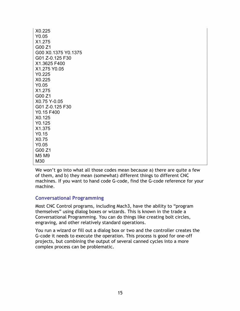
We won’t go into what all those codes mean because a) there are quite a few of them, and b) they mean (somewhat) different things to different CNC machines. If you want to hand code G-code, find the G-code reference for your machine.
Conversational Programming
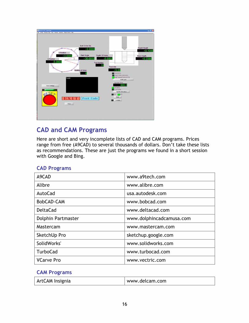
Most CNC Control programs, including Mach3, have the ability to “program themselves” using dialog boxes or wizards. This is known in the trade a Conversational Programming. You can do things like creating bolt circles, engraving, and other relatively standard operations.
You run a wizard or fill out a dialog box or two and the controller creates the G-code it needs to execute the operation. This process is good for one-off projects, but combining the output of several canned cycles into a more complex process can be problematic.
16
CAD and CAM Programs Here are short and very incomplete lists of CAD and CAM programs. Prices range from free (A9CAD) to several thousands of dollars. Don’t take these lists as recommendations. These are just the programs we found in a short session with Google and Bing.
CAD Programs
A9CAD www.a9tech.com
Alibre www.alibre.com
AutoCad usa.autodesk.com
BobCAD-CAM www.bobcad.com
DeltaCad www.deltacad.com
Dolphin Partmaster www.dolphincadcamusa.com
Mastercam www.mastercam.com
SketchUp Pro sketchup.google.com
SolidWorks' www.solidworks.com
TurboCad www.turbocad.com
VCarve Pro www.vectric.com
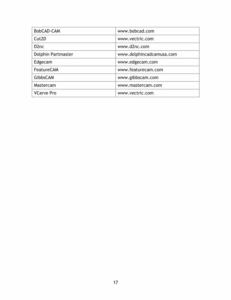
CAM Programs
ArtCAM Insignia www.delcam.com
17
BobCAD-CAM www.bobcad.com
Cut2D www.vectric.com
D2nc www.d2nc.com
Dolphin Partmaster www.dolphincadcamusa.com
Edgecam www.edgecam.com
FeatureCAM www.featurecam.com
GibbsCAM www.gibbscam.com
Mastercam www.mastercam.com
VCarve Pro www.vectric.com