What is Mechatronics? Mechatronics is the synergistic combination of mechanical engineering,...
33
-
Upload
nicholas-beasley -
Category
Documents
-
view
243 -
download
4
Transcript of What is Mechatronics? Mechatronics is the synergistic combination of mechanical engineering,...


What is Mechatronics?
Mechatronics is the synergistic combination of mechanical engineering, electronics, controls engineering, and computers, all integrated through the design process. It involves the application of complex decision making to the operation of physical systems. Mechatronic systems depend for their unique functionality on computer software.

Mechatronics
Mechatronics is the integration of computer Engineering, e
lectronics, control engineering and mechanical engineering.
The integration across the traditional boundaries of mecha
nical engineering, electronics and control engineering has to oc
cur at the earliest stages of the design process if cheaper, more
reliable, and more flexible systems are to be developed.
Mechatronics involves sensors and measurement systems,
drive and actuation systems, analysis of the behavior of system
s, control systems, and micro-processor systems.

Mechatronics
• The primary disciplines important in the design of mechatronic systems include mechanics, electronics, control and computer engineering.”
• A mechatronic system engineer must be able to design and select analog and digital circuits, microprocessor-based components, mechanical devices, sensors and actuators, and controls so that the final product achieves a desired goal.
Term coined in Japanin the late 60’s
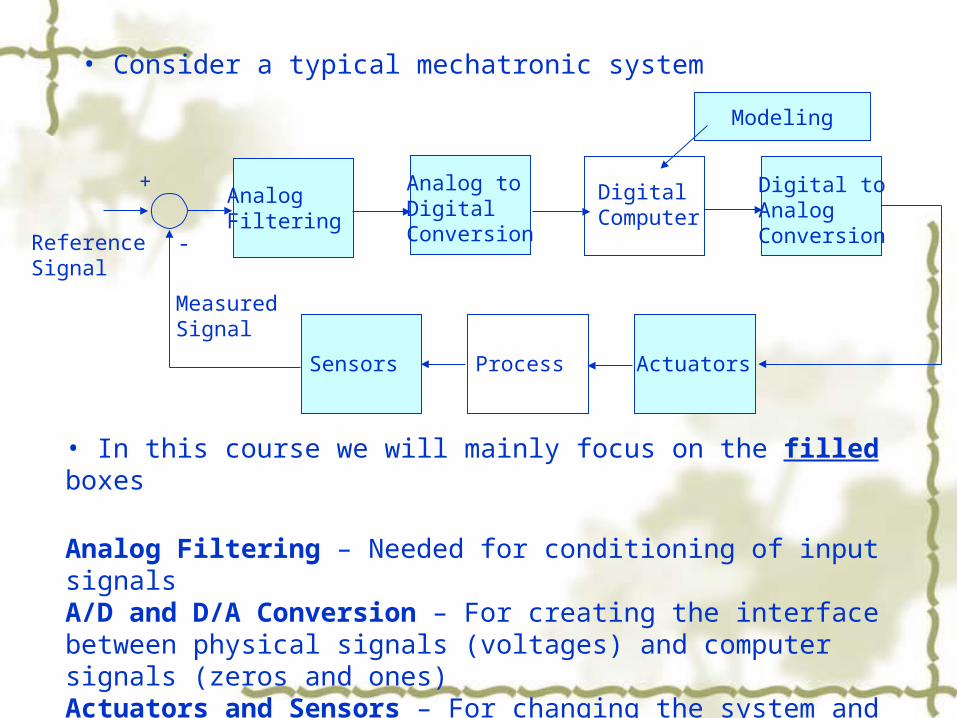
• Consider a typical mechatronic system
AnalogFiltering
Analog toDigitalConversion
DigitalComputer
Digital toAnalogConversion
ActuatorsProcessSensors
ReferenceSignal
MeasuredSignal
+
-
• In this course we will mainly focus on the filled boxes
Analog Filtering – Needed for conditioning of input signalsA/D and D/A Conversion – For creating the interface between physical signals (voltages) and computer signals (zeros and ones) Actuators and Sensors – For changing the system and measuring its response Mathematical modeling – For design and control purposes
Modeling

Examples
• Brushless dc motor• Vending machines• ATM machines• Inkjet printers• Photocopiers• Air conditioning units• Internal combustion (IC) engine• Gear pump•Auto camera•Washing machines•Automobile•Mobile Phone
Large number of movies located at http://www.engr.colostate.edu/~dga/video_demos/mechatronics/index.html


1.2 Systems What is a System?
Group of Components that work together for a purpose Service Product Process
Attributes: discernable manifestations of the components
Relationships are links between Components & Attributes

Components Properties Properties & Behavior of each Component has an
influence on the properties & behavior of the set as a whole
Properties & Behaviors of each component of the set depends on the properties & behaviors of at least one other component
Each possible subset of the components has the two properties listed above: I.E. the components cannot be divided into independent subsets

A system can be thought of as a black box which has an input and an output.

A sensor-- responding to the quantity being measured by giving as
its output a signal which is related to the quantity.
A signal conditioner—taking the signal from the sensor and
converting it into a condition which is suitable for either display, or, in
the case of a control system, for use to exercise control.
A display system—displaying the output of signal conditioner.
1.3 Measurement systems

1.4 Control systems
1.4.1 Open- and closed-loop systems
Open-loop systems—simple, low cost and good reliability.
Closed-loop systems—accurate, more complex and high
cost.

1.4.2 Basic elements of a closed-loop system
1). Comparison element 2). Control element 3). Correction element (actuator) 4). Process element 5). Measurement element


1.4.3 Sequential controllers
Washing machine system
1.4.4 Microprocessor-based controllers (programmable logic controller)
Microprocessor-based controller which uses programmable memory to store instructions and to implement functions such as logic, sequence, timing counting and arithmetic to control events.

1.5Digital control and logic gates Analogue control is when the control is continuous with input signals from
sensors and output signals to the actuators being continuously variable.
Digital control is when the control is discontinuous.
1.5.1 Logic gates

Digital Circuits – NOT Gate Logic Diagram
Single input
Truth Table
Boolean expression:● Also referred to as an Also referred to as an
inverterinverter
A X
A X
0 1
1 0
AX =

Digital Circuits – AND Gate
A
B
X
A B X
0 0 0
0 1 0
1 0 0
1 1 1
Logic Diagram 2-input AND Gate
Boolean Expression:
Truth Table
X = AB
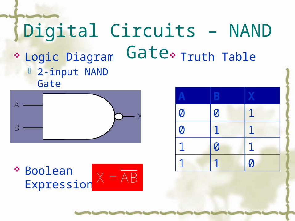
Digital Circuits – NAND Gate
A B X
0 0 1
0 1 1
1 0 1
1 1 0
A
B
X
Logic Diagram 2-input NAND Gate
Boolean Expression:
Truth Table
X = AB

Digital Circuits – NAND GateT0 T1 T2 T3 T4
A
B
X
0 0 1 1
0 01 1
11 1 0
A B X
0 0 1
0 1 1
1 0 1
1 1 0
Timing Diagram 2-input NAND Gate
Truth Table

A
C
XB
Digital Circuits – NAND Gate Logic Diagram
3-input NAND Gate
Boolean Expression:
A B C X
0 0 0 1
0 0 1 1
0 1 0 1
0 1 1 1
1 0 0 1
1 0 1 1
1 1 0 1
1 1 1 0
Truth Table
X = ABC

NAND Gate
Referred to as a universal gate – any of the basic logical operations can be performed with NAND gates.
Any digital system can be implemented with NAND gates alone.

NAND Gate Configuring a NAND gate as an Inverter
AA
A A

NAND Gate Configuring a NAND gate as an AND gate
ABC
ABC
X = ABC
ABCABC = ABC

NAND Gate Configuring a NAND gate as an OR
gate
A B X
0 0 0
0 1 1
1 0 1
1 1 1
Truth Table
A
BX
A
B
A
B
AB = A+B= A+B
DeMorgan’s Theorem:X+Y = XYXY = X+Y

1.6 The mechatronics approach
Mechatronics involves the bringing together of a number
of technologies: mechanical engineering, electronic engineeri
ng, electrical engineering, computer technology, and control e
ngineering.
Mechatronics can be considered to be the application of c
omputer-based digital control techniques, through electronic a
nd electric interfaces, to mechanical engineering problem.


Homework: page 15 problem 4,8

LEVELS OF EDUCATIONAL OBJECTIVES (Bloom, 1956)
Knowledge - recall, recognition Comprehension - understanding the literal message,
stating the message in one’s own words Application - carrying over understanding into a new area Analysis - breaking material down into its constituent parts
and detecting relationships of the parts Synthesis - putting together elements and parts to form a
whole, creating something new Evaluation - making judgments about the value of ideas,
works, solutions, etc.

Educational Objectives To understand, apply and synthesize mechatroni
cs systems To understand, apply and synthesize computer c
ontrolled systems To develop increased creativity, teamwork, and
presentation skills To develop a greater awareness and respect for
things beyond the traditional ME boundaries To develop engineering common sense - proble
m avoiding and solving skills


