What is an Antenna? - University of Delawaremirotzni/ELEG413/antennas.pdf · What is an Antenna?...
72
What is an Antenna? Time varying charges cause radiation but NOT everything that radiates is an antenna! + - Now this is an antenna Not an antenna
Transcript of What is an Antenna? - University of Delawaremirotzni/ELEG413/antennas.pdf · What is an Antenna?...
What is an Antenna?
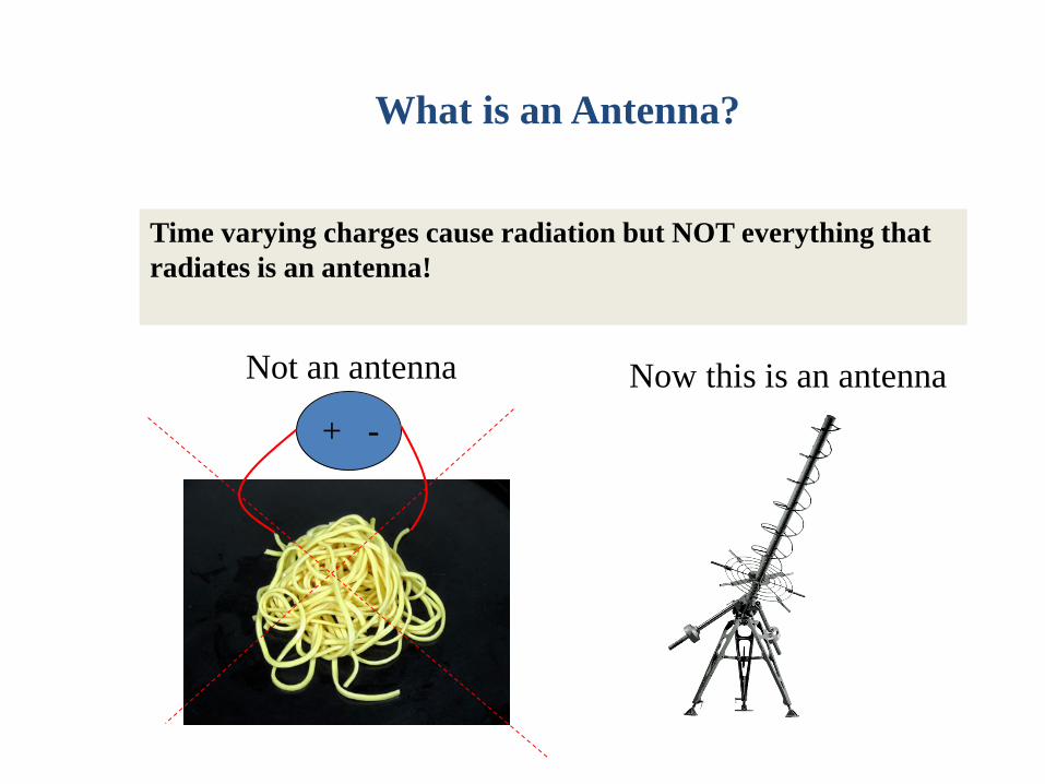
Time varying charges cause radiation but NOT everything that radiates is an antenna!
+ -Now this is an antennaNot an antenna
What is an Antenna?
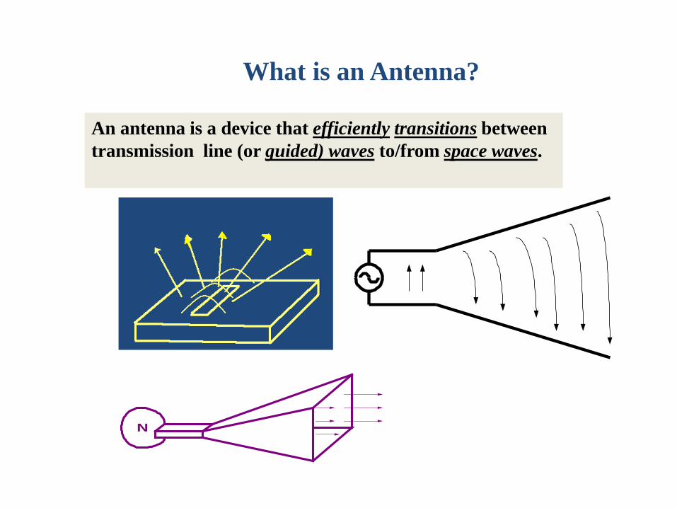
An antenna is a device that efficiently transitions between transmission line (or guided) waves to/from space waves.
N
What properties does a good antenna have?
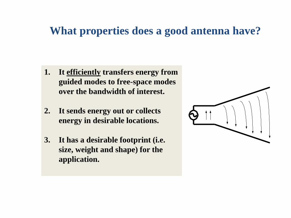
1. It efficiently transfers energy from guided modes to free-space modes over the bandwidth of interest.
2. It sends energy out or collects energy in desirable locations.
3. It has a desirable footprint (i.e. size, weight and shape) for the application.
Antenna Types: Wire Antennas
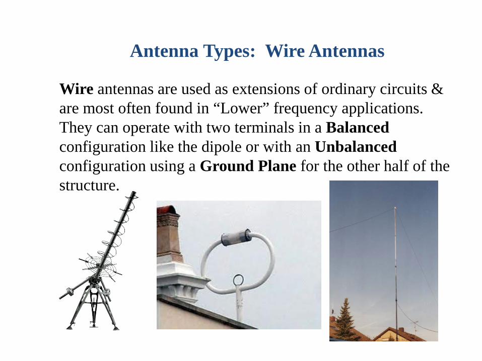
Wire antennas are used as extensions of ordinary circuits & are most often found in “Lower” frequency applications. They can operate with two terminals in a Balancedconfiguration like the dipole or with an Unbalancedconfiguration using a Ground Plane for the other half of the structure.
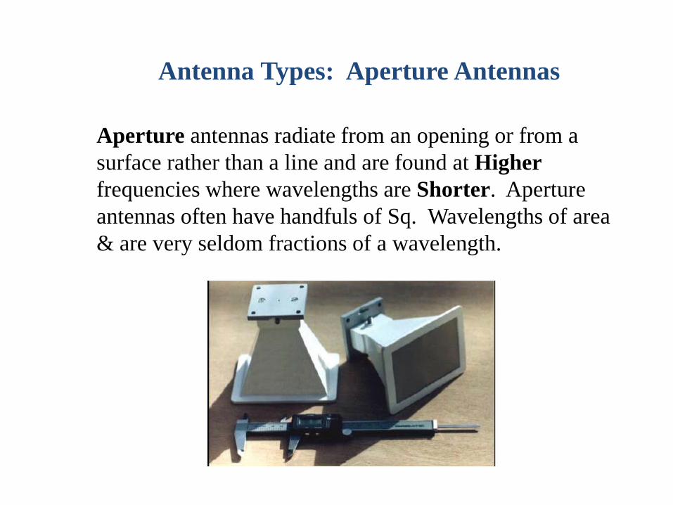
Antenna Types: Aperture Antennas
Aperture antennas radiate from an opening or from a surface rather than a line and are found at Higherfrequencies where wavelengths are Shorter. Aperture antennas often have handfuls of Sq. Wavelengths of area & are very seldom fractions of a wavelength.
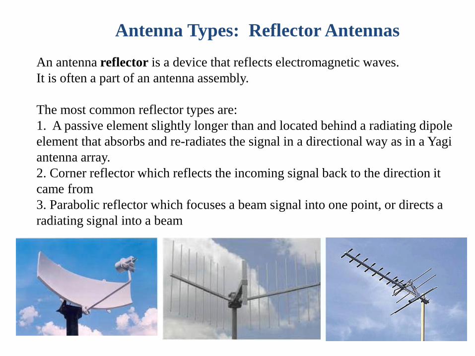
Antenna Types: Reflector AntennasAn antenna reflector is a device that reflects electromagnetic waves.It is often a part of an antenna assembly.
The most common reflector types are:1. A passive element slightly longer than and located behind a radiating dipole element that absorbs and re-radiates the signal in a directional way as in a Yagi antenna array.2. Corner reflector which reflects the incoming signal back to the direction it came from 3. Parabolic reflector which focuses a beam signal into one point, or directs a radiating signal into a beam
Fundamental Antenna Parameters
1. Radiation PatternAn antenna radiation pattern is defined as “a graphicalrepresentation of the radiation properties of the antennaas a function of space coordinates. In most cases, theradiation pattern is determined in the far-field region.Radiation properties include radiation intensity, fieldstrength, phase or polarization.
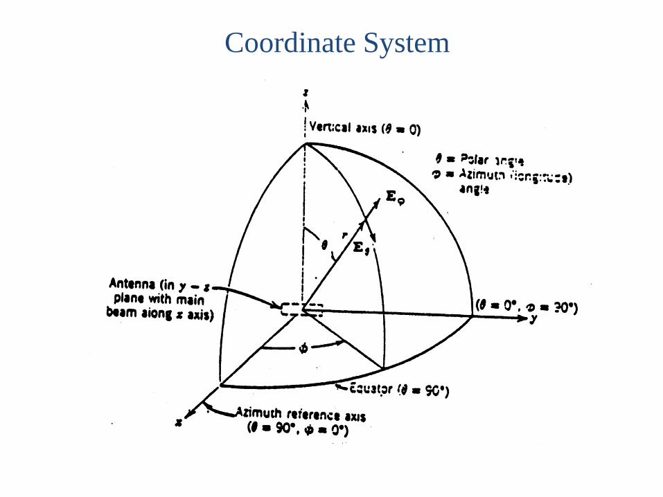
Coordinate System
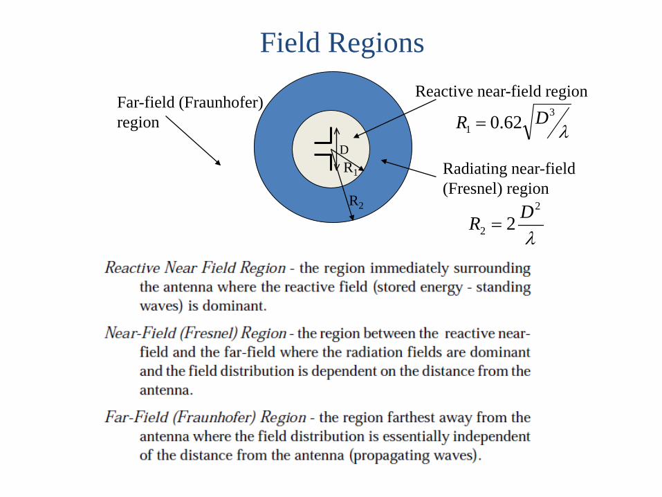
Field Regions
DR1
R2
Reactive near-field region
λ3
1 62.0 DR =
Radiating near-field (Fresnel) region
λ
2
2 2 DR =
Far-field (Fraunhofer) region
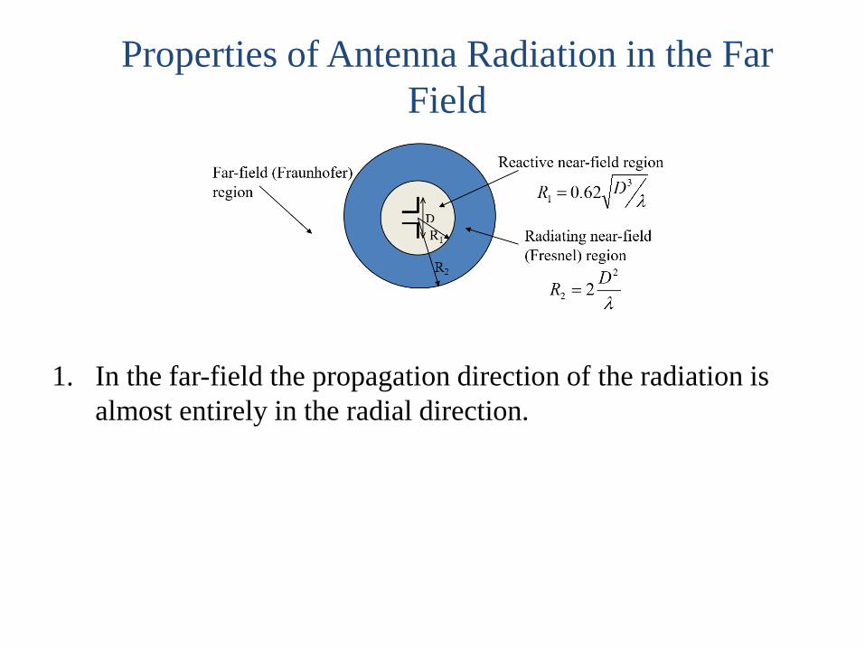
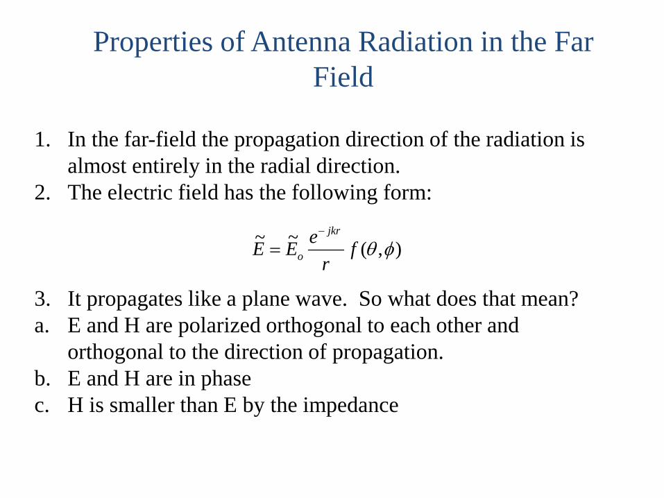
Properties of Antenna Radiation in the Far Field
1. In the far-field the propagation direction of the radiation is almost entirely in the radial direction.
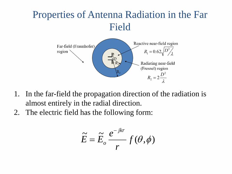
Properties of Antenna Radiation in the Far Field
1. In the far-field the propagation direction of the radiation is almost entirely in the radial direction.
2. The electric field has the following form:
),(~~ φθfr
eEEjkr
o
−
=
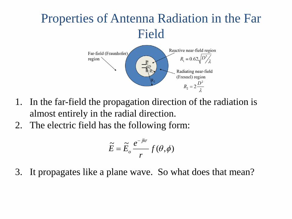
Properties of Antenna Radiation in the Far Field
1. In the far-field the propagation direction of the radiation is almost entirely in the radial direction.
2. The electric field has the following form:
3. It propagates like a plane wave. So what does that mean?
),(~~ φθfr
eEEjkr
o
−
=
Properties of Antenna Radiation in the Far Field
1. In the far-field the propagation direction of the radiation is almost entirely in the radial direction.
2. The electric field has the following form:
3. It propagates like a plane wave. So what does that mean?a. E and H are polarized orthogonal to each other and
orthogonal to the direction of propagation.b. E and H are in phasec. H is smaller than E by the impedance
),(~~ φθfr
eEEjkr
o
−
=
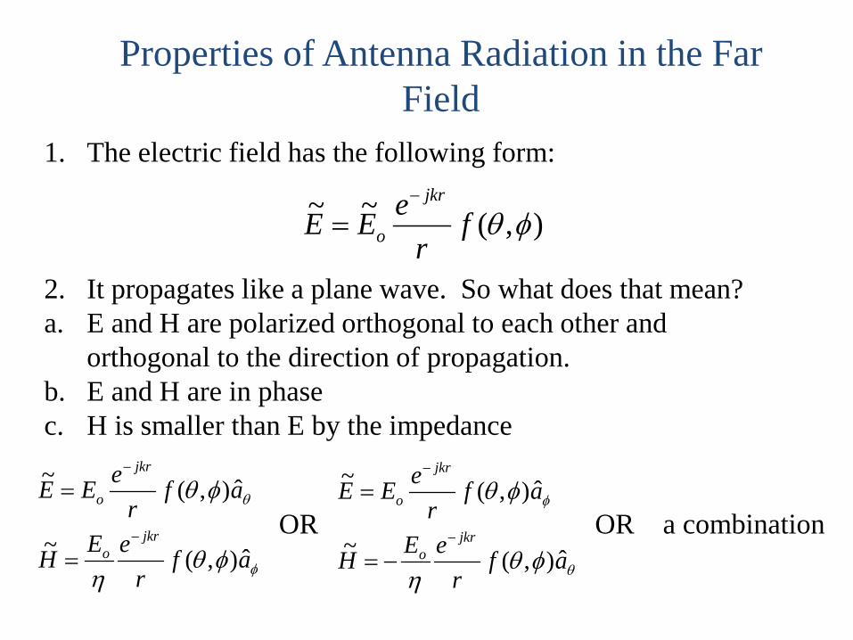
Properties of Antenna Radiation in the Far Field
1. The electric field has the following form:
2. It propagates like a plane wave. So what does that mean?a. E and H are polarized orthogonal to each other and
orthogonal to the direction of propagation.b. E and H are in phasec. H is smaller than E by the impedance
),(~~ φθfr
eEEjkr
o
−
=
φ
θ
φθη
φθ
afr
eEH
afr
eEE
jkro
jkr
o
ˆ),(~
ˆ),(~
−
−
=
=OR
θ
φ
φθη
φθ
afr
eEH
afr
eEE
jkro
jkr
o
ˆ),(~
ˆ),(~
−
−
−=
=OR a combination
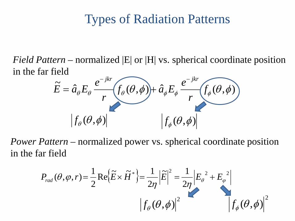
Types of Radiation Patterns
Power Pattern – normalized power vs. spherical coordinate positionin the far field
Field Pattern – normalized |E| or |H| vs. spherical coordinate positionin the far field
),(ˆ),(ˆ~ φθφθ φφφθθθ fr
eEafr
eEaEjkrjkr −−
+=
),( φθθf
222*
21~
21~~Re
21),,( ϕθηη
ϕθ EEEHErPrad +==×=
),( φθφf
2),( φθθf2
),( φθφf
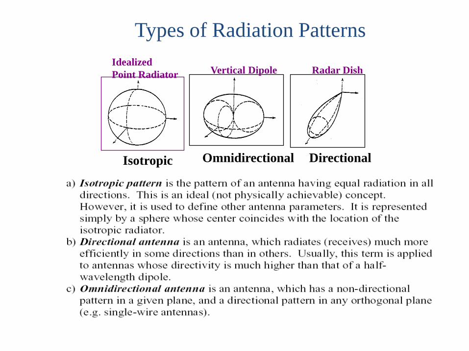
IdealizedPoint Radiator Vertical Dipole Radar Dish
Isotropic Omnidirectional Directional
Types of Radiation Patterns
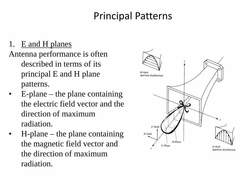
Principal Patterns
1. E and H planesAntenna performance is often
described in terms of its principal E and H plane patterns.
• E-plane – the plane containing the electric field vector and the direction of maximum radiation.
• H-plane – the plane containing the magnetic field vector and the direction of maximum radiation.
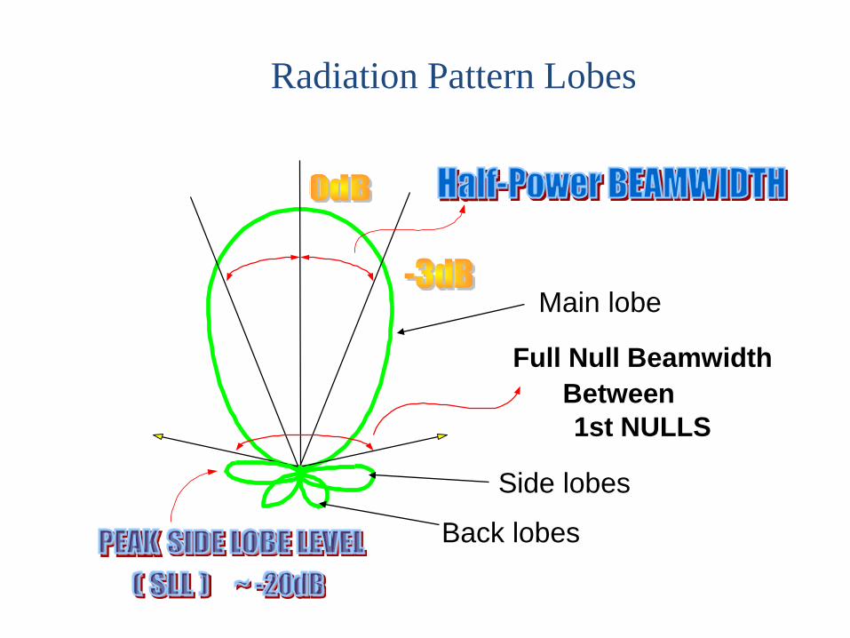
Full Null BeamwidthBetween1st NULLS
Radiation Pattern Lobes
Main lobe
Side lobes
Back lobes
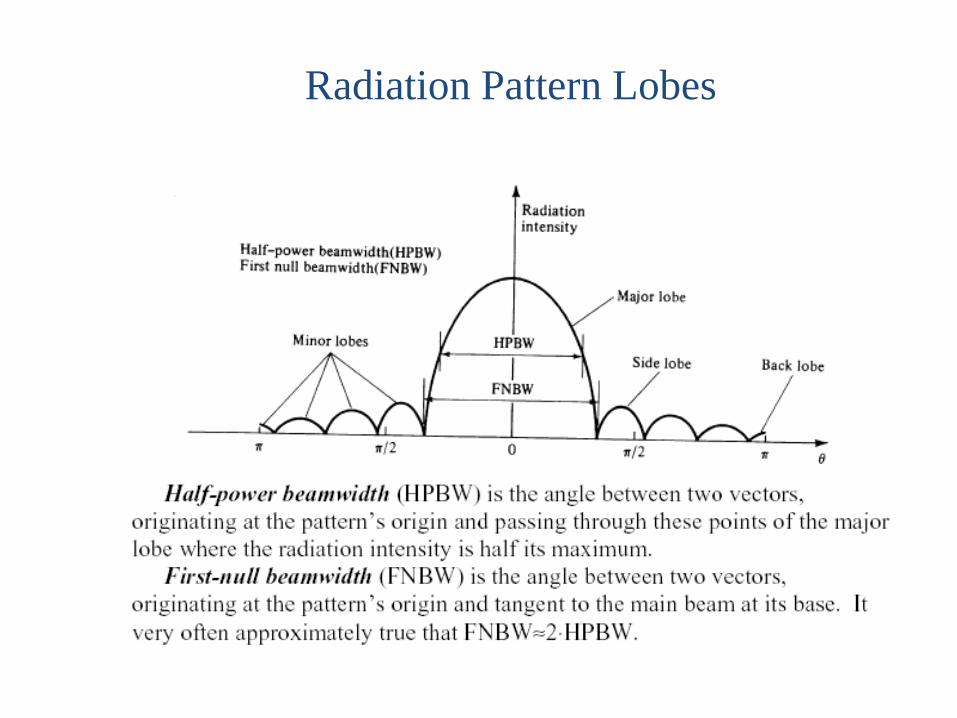
Radiation Pattern Lobes
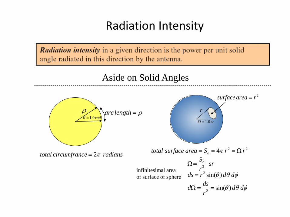
Radiation Intensity
Aside on Solid Angles
ρ ρ=lengtharcrad0.1=θ
r
sr0.1=Ω
2rareasurface =
radianscecircumfrantotal π2=224 rrSareasurfacetotal o Ω=== π
srrSo
2=Ω
φθθ ddrds )sin(2=infinitesimal areaof surface of sphere
φθθ ddrdsd )sin(2 ==Ω
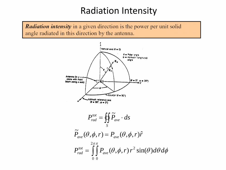
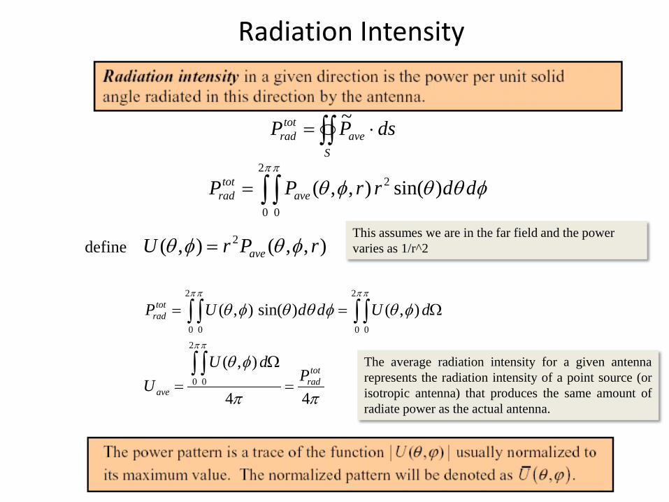
Radiation Intensity
∫∫ ⋅=S
avetot
rad dsPP ~
φθθφθ
φθφθππ
ddrrPP
rrPrP
avetot
rad
aveave
)sin(),,(
ˆ),,(),,(~
22
0 0∫ ∫=
=
Radiation Intensity
∫∫ ⋅=S
avetot
rad dsPP ~
φθθφθππ
ddrrPP avetot
rad )sin(),,( 22
0 0∫ ∫=
define ),,(),( 2 rPrU ave φθφθ =This assumes we are in the far field and the power varies as 1/r^2
ππ
φθ
φθφθθφθ
ππ
πππ π
44
),(
),()sin(),(
2
0 0
2
0 0
2
0 0
totrad
ave
totrad
PdU
U
dUddUP
=Ω
=
Ω==
∫ ∫
∫ ∫∫ ∫
The average radiation intensity for a given antennarepresents the radiation intensity of a point source (orisotropic antenna) that produces the same amount ofradiate power as the actual antenna.
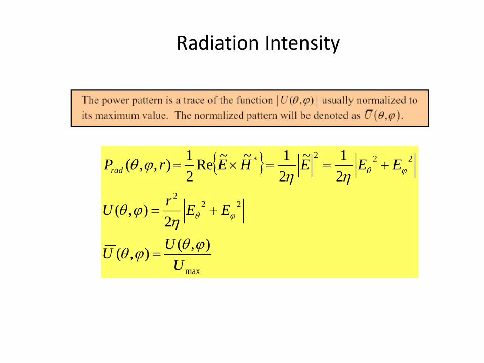
Radiation Intensity
max
222
222*
),(),(
2),(
21~
21~~Re
21),,(
UUU
EErU
EEEHErPrad
ϕθϕθ
ηϕθ
ηηϕθ
ϕθ
ϕθ
=
+=
+==×=
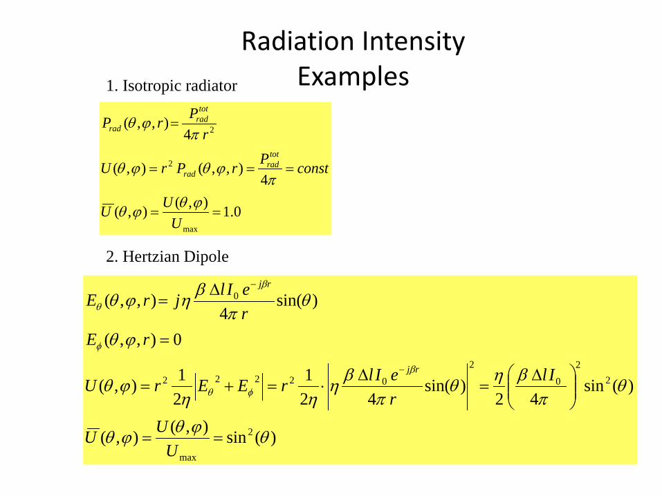
Radiation IntensityExamples
0.1),(),(
4),,(),(
4),,(
max
2
2
==
===
=
UUU
constPrPrU
rPrP
totrad
rad
totrad
rad
ϕθϕθ
πϕθϕθ
πϕθ
1. Isotropic radiator
2. Hertzian Dipole
)(sin),(),(
)(sin42
)sin(42
121),(
0),,(
)sin(4
),,(
2
max
22
0
2
02222
0
θϕθϕθ
θπ
βηθπ
βηηη
ϕθ
ϕθ
θπ
βηϕθ
β
φθ
φ
β
θ
==
∆=
∆⋅=+=
=
∆=
−
−
UUU
IlreIlrEErU
rEreIljrE
rj
rj
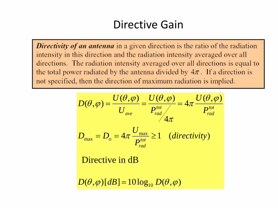
Directive Gain
),(log10][),(
)(14
),(4
4
),(),(),(
10
maxmax
ϕθϕθ
π
ϕθπ
π
ϕθϕθϕθ
DdBD
ydirectivitP
UDD
PU
PU
UUD
totrad
o
totrad
totradave
=
≥==
===
Directive in dB
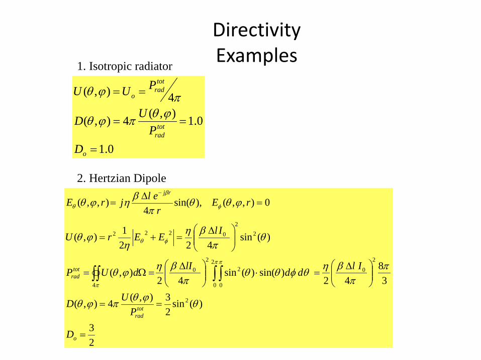
DirectivityExamples
0.1
0.1),(4),(
4),(
=
==
==
o
totrad
totrad
o
DP
UD
PUU
ϕθπϕθ
πϕθ
1. Isotropic radiator
2. Hertzian Dipole
23
)(sin23),(4),(
38
42)sin()(sin
42),(
)(sin422
1),(
0),,(),sin(4
),,(
2
2
02
0 0
22
0
4
22
0222
=
==
∆=⋅
∆=Ω=
∆=+=
=∆
=
∫ ∫∫∫
−
o
totrad
totrad
rj
D
PUD
IlddlIdUP
IlEErU
rEr
eljrE
θϕθπϕθ
ππ
βηθφθθπ
βηϕθ
θπ
βηη
ϕθ
ϕθθπ
βηϕθ
ππ
π
φθ
φ
β
θ
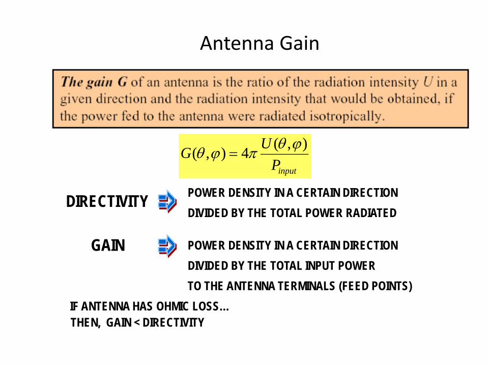
Antenna Gain
inputPUG ),(4),( ϕθπϕθ =
POWER DENSITY IN A CERTAIN DIRECTIONDIVIDED BY THE TOTAL POWER RADIATED
POWER DENSITY IN A CERTAIN DIRECTIONDIVIDED BY THE TOTAL INPUT POWERTO THE ANTENNA TERMINALS (FEED POINTS)
IF ANTENNA HAS OHMIC LOSS…THEN, GAIN < DIRECTIVITY
DIRECTIVITY
GAIN
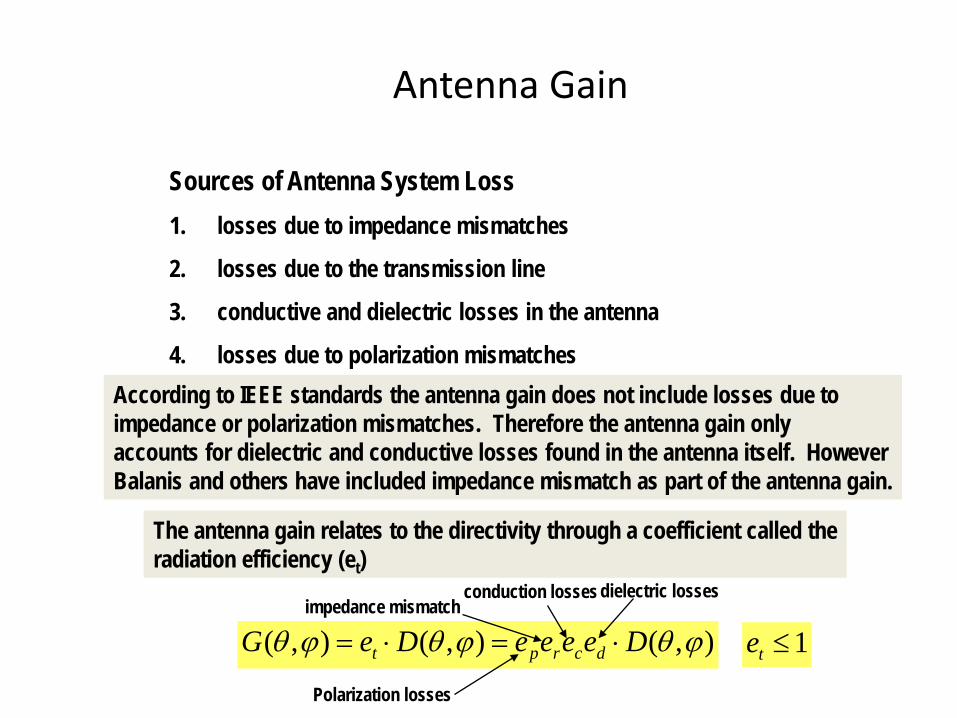
Antenna Gain
Sources of Antenna System Loss1. losses due to impedance mismatches
2. losses due to the transmission line
3. conductive and dielectric losses in the antenna
4. losses due to polarization mismatchesAccording to IEEE standards the antenna gain does not include losses due toimpedance or polarization mismatches. Therefore the antenna gain only accounts for dielectric and conductive losses found in the antenna itself. HoweverBalanis and others have included impedance mismatch as part of the antenna gain.
The antenna gain relates to the directivity through a coefficient called theradiation efficiency (et)
),(),(),( ϕθϕθϕθ DeeeeDeG dcrpt ⋅=⋅=
conduction losses dielectric losses
1≤teimpedance mismatch
Polarization losses
Overall Antenna Efficiency
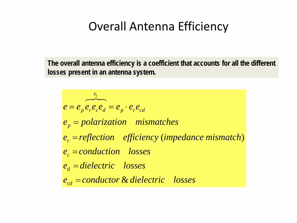
The overall antenna efficiency is a coefficient that accounts for all the differentlosses present in an antenna system.
lossesdielectricconductorelossesdielectrice
lossesconductionemismatchimpedanceefficiencyreflectione
mismatchesonpolarizatieeeeeeeee
cd
d
c
r
p
cdrp
e
dcrp
t
&
)(
====
=
⋅==
Reflection Efficiency
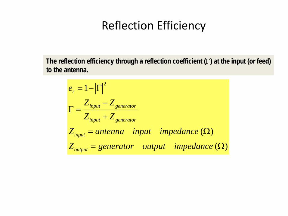
The reflection efficiency through a reflection coefficient (Γ) at the input (or feed)to the antenna.
)()(
1 2
Ω=
Ω=
+
−=Γ
Γ−=
impedanceoutputgeneratorZimpedanceinputantennaZ
ZZZZ
e
output
input
generatorinput
generatorinput
r
Radiation Resistance
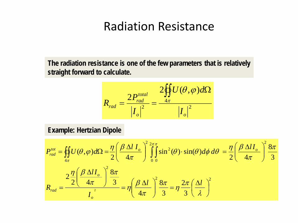
The radiation resistance is one of the few parameters that is relativelystraight forward to calculate.
24
2
),(22
oo
totalrad
radI
dU
IPR
∫∫ Ω== π
ϕθ
Example: Hertzian Dipole
22
2
22
0 0
22
4
32
38
43
842
2
38
42)sin()(sin
42),(
2
∆=
∆=
∆
=
∆=⋅
∆=Ω= ∫ ∫∫∫
λπηπ
πβη
ππ
βη
ππ
βηθφθθπ
βηϕθππ
π
llI
Il
R
IlddIldUP
o
o
rad
oototrad
Radiation Resistance
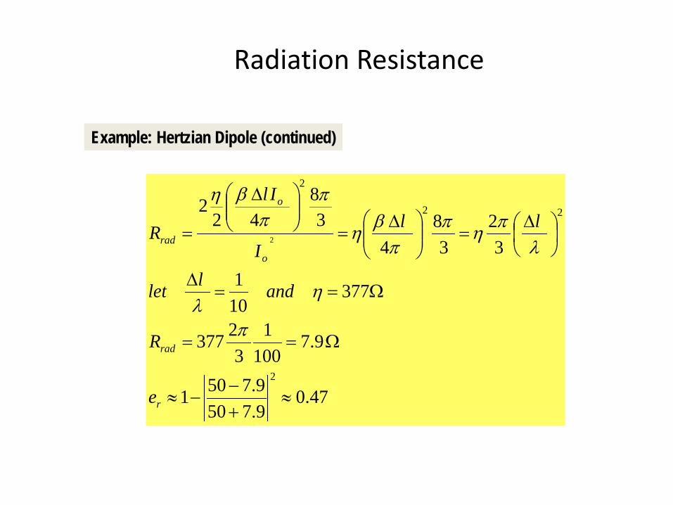
Example: Hertzian Dipole (continued)
47.09.7509.7501
9.7100
13
2377
377101
32
38
43
842
2
2
22
2
2
≈+−
−≈
Ω==
Ω==∆
∆=
∆=
∆
=
r
rad
o
o
rad
e
R
andllet
llI
Il
R
π
ηλ
λπηπ
πβη
ππ
βη
Antenna Radiation Efficiency
radcd
rad
ohmicrad
rad
total
radcd RR
RPP
PPPe
+=
+==
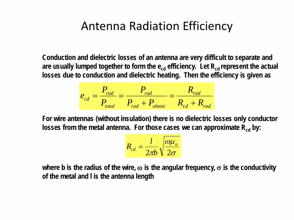
Conduction and dielectric losses of an antenna are very difficult to separate andare usually lumped together to form the ecd efficiency. Let Rcd represent the actuallosses due to conduction and dielectric heating. Then the efficiency is given as
For wire antennas (without insulation) there is no dielectric losses only conductorlosses from the metal antenna. For those cases we can approximate Rcd by:
σωµ
π 22o
cd blR =
where b is the radius of the wire, ω is the angular frequency, σ is the conductivityof the metal and l is the antenna length
Antenna Radiation Efficiency
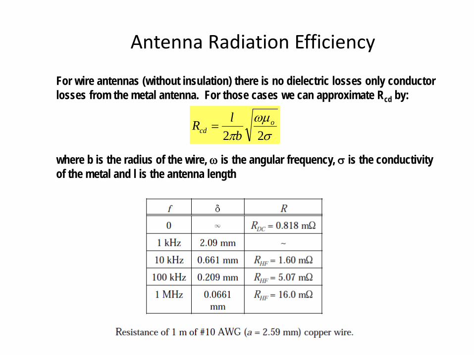
For wire antennas (without insulation) there is no dielectric losses only conductorlosses from the metal antenna. For those cases we can approximate Rcd by:
σωµ
π 22o
cd blR =
where b is the radius of the wire, ω is the angular frequency, σ is the conductivityof the metal and l is the antenna length
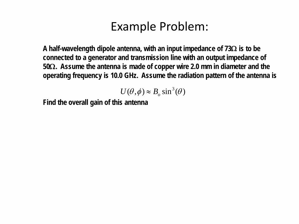
Example Problem:A half-wavelength dipole antenna, with an input impedance of 73Ω is to beconnected to a generator and transmission line with an output impedance of50Ω. Assume the antenna is made of copper wire 2.0 mm in diameter and theoperating frequency is 10.0 GHz. Assume the radiation pattern of the antenna is
Find the overall gain of this antenna)(sin),( 3 θφθ oBU ≈
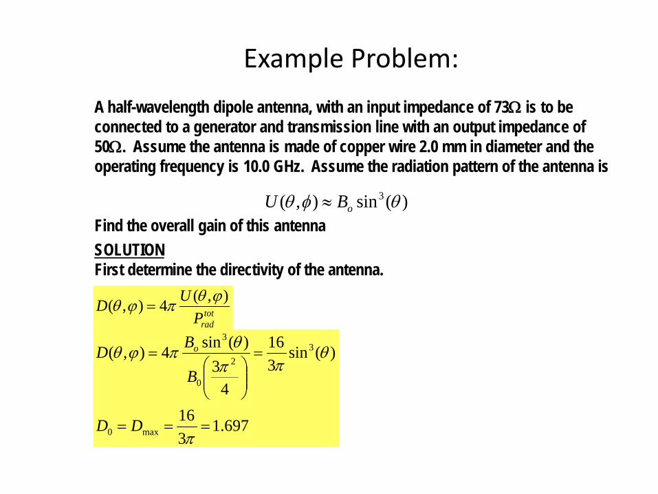
Example Problem:A half-wavelength dipole antenna, with an input impedance of 73Ω is to beconnected to a generator and transmission line with an output impedance of50Ω. Assume the antenna is made of copper wire 2.0 mm in diameter and theoperating frequency is 10.0 GHz. Assume the radiation pattern of the antenna is
Find the overall gain of this antennaSOLUTIONFirst determine the directivity of the antenna.
)(sin),( 3 θφθ oBU ≈
totradP
UD ),(4),( ϕθπϕθ =
697.1316
)(sin316
43
)(sin4),(
max0
32
0
3
===
=
=
π
θππ
θπϕθ
DD
B
BD o
Example Problem: Continued
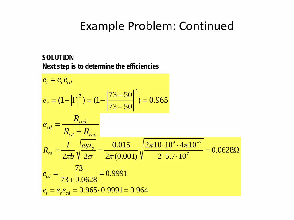
SOLUTIONNext step is to determine the efficiencies
965.0)507350731()1(
22 =
+−
−=Γ−=
=
r
cdrt
e
eee
radcd
radcd RR
Re+
=
964.09991.0965.0
9991.00628.073
73
0628.0107.52
10410102)001.0(2
015.022 7
79
=⋅==
=+
=
Ω=⋅⋅⋅⋅
==−
cdrt
cd
ocd
eee
e
blR ππ
πσωµ
π
Example Problem: Continued
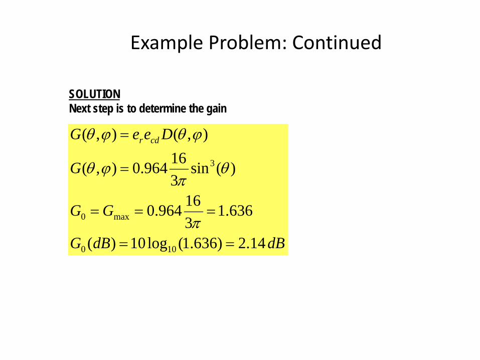
SOLUTIONNext step is to determine the gain
dBdBG
GG
G
DeeG cdr
14.2)636.1(log10)(
636.1316964.0
)(sin316964.0),(
),(),(
100
max0
3
==
===
=
=
π
θπ
ϕθ
ϕθϕθ
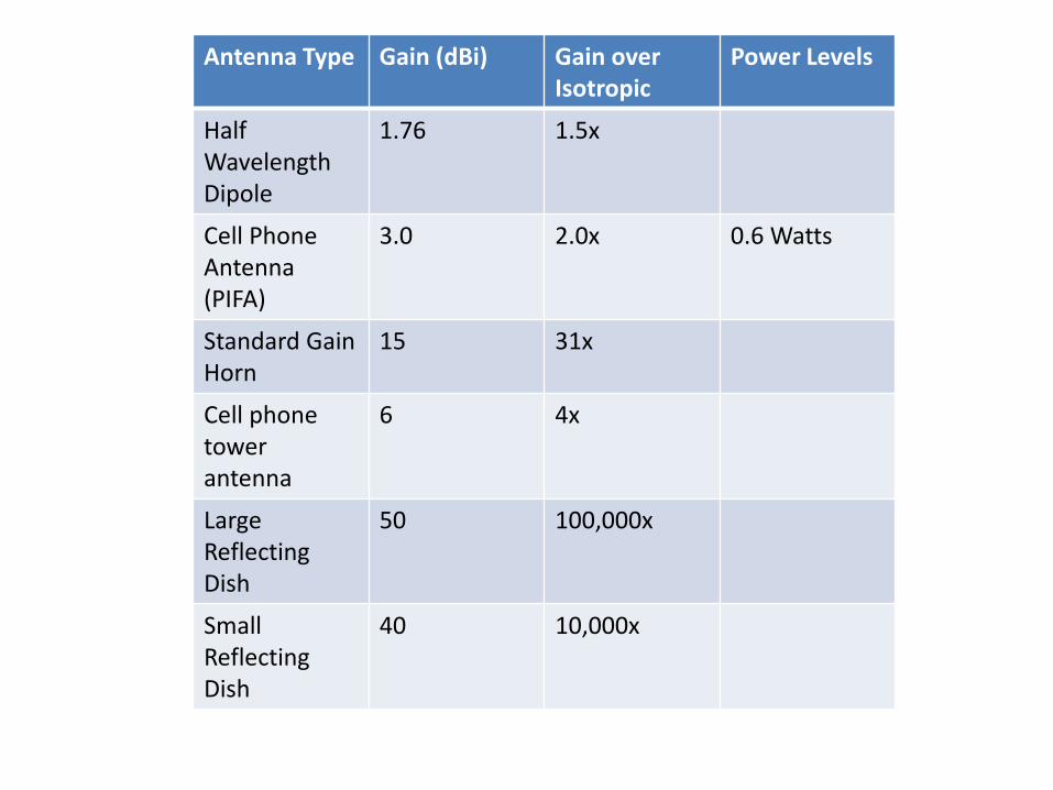
Antenna Type Gain (dBi) Gain over Isotropic
Power Levels
HalfWavelength Dipole
1.76 1.5x
Cell Phone Antenna(PIFA)
3.0 2.0x 0.6 Watts
Standard Gain Horn
15 31x
Cell phone tower antenna
6 4x
LargeReflecting Dish
50 100,000x
Small Reflecting Dish
40 10,000x
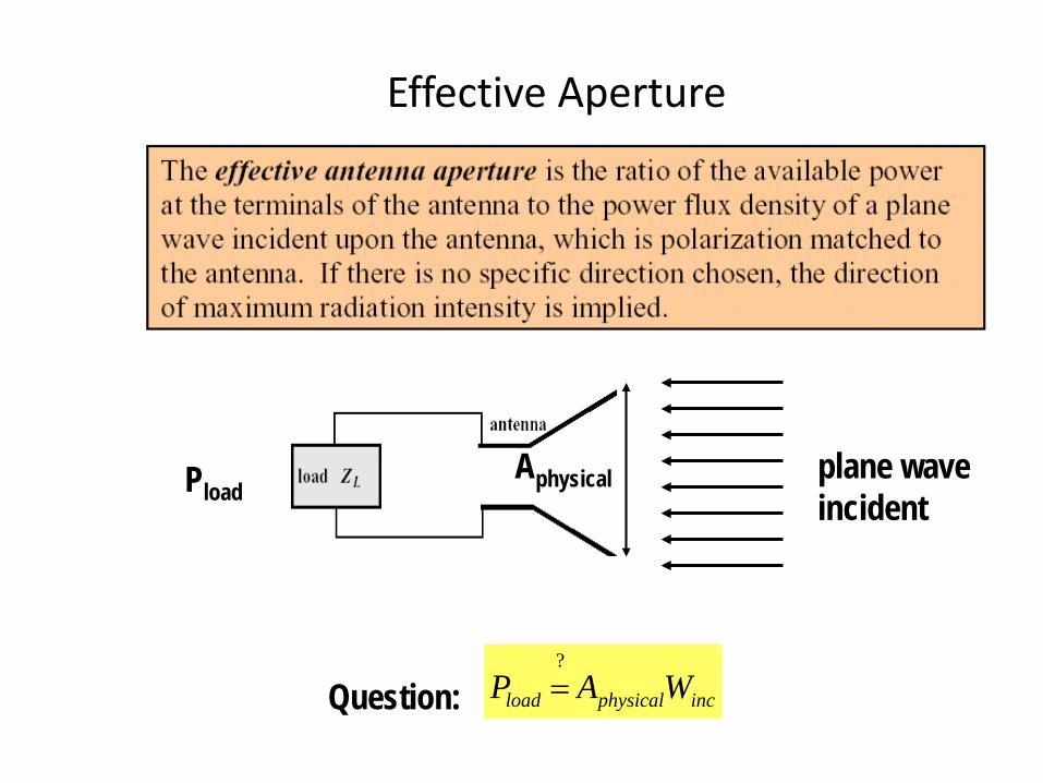
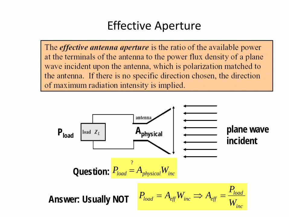
Effective Aperture
plane waveincident
AphysicalPload
incphysicalload WAP?=Question:
Effective Aperture
plane waveincident
AphysicalPload
incphysicalload WAP?=Question:
Answer: Usually NOTinc
loadeffinceffload W
PAWAP =⇒=
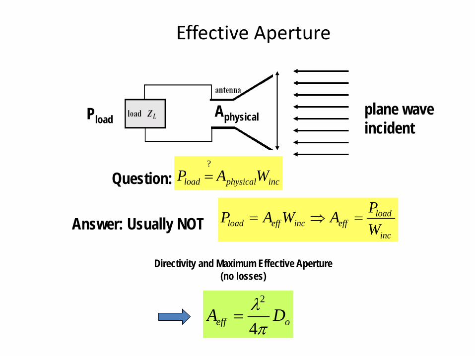
Effective Aperture
plane waveincident
AphysicalPload
incphysicalload WAP?=Question:
Answer: Usually NOTinc
loadeffinceffload W
PAWAP =⇒=
oeff DAπλ4
2
=
Directivity and Maximum Effective Aperture (no losses)
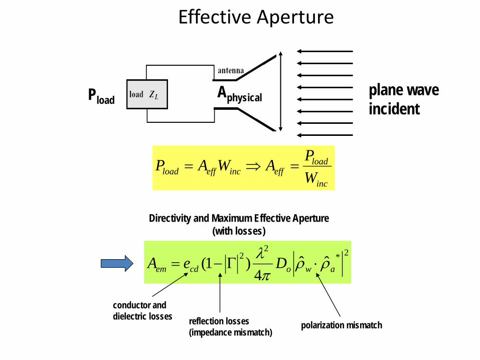
Effective Aperture
plane waveincident
AphysicalPload
inc
loadeffinceffload W
PAWAP =⇒=
Directivity and Maximum Effective Aperture (with losses)
2*2
2 ˆˆ4
)1( awocdem DeA ρρπλ
⋅Γ−=
conductor and dielectric losses reflection losses
(impedance mismatch)polarization mismatch
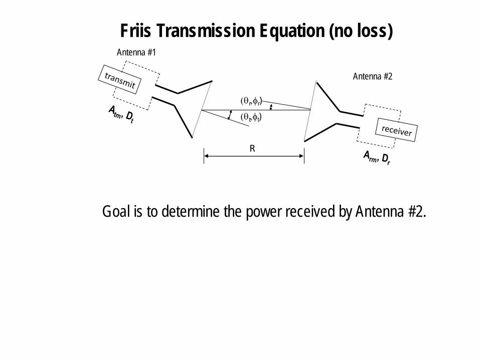
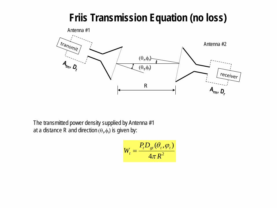
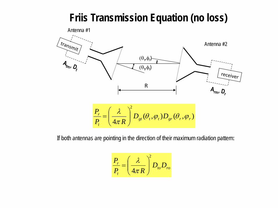
Friis Transmission Equation (no loss)
Antenna #2
Antenna #1
R
Goal is to determine the power received by Antenna #2.
(θt,φt)(θr,φr)
Friis Transmission Equation (no loss)
Antenna #2
Antenna #1
R
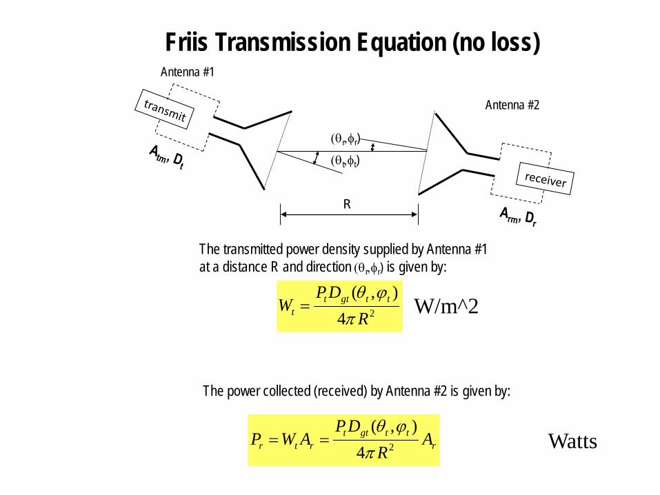
The transmitted power density supplied by Antenna #1at a distance R and direction (θr,φr) is given by:
24),(
RDP
W ttgttt π
ϕθ=
(θt,φt)(θr,φr)
Friis Transmission Equation (no loss)
Antenna #2
Antenna #1
R
The transmitted power density supplied by Antenna #1at a distance R and direction (θr,φr) is given by:
24),(
RDP
W ttgttt π
ϕθ=
(θt,φt)(θr,φr)
The power collected (received) by Antenna #2 is given by:
rttgtt
rtr AR
DPAWP 24
),(π
ϕθ==
W/m^2
Watts
Friis Transmission Equation (no loss)
Antenna #2
Antenna #1
R
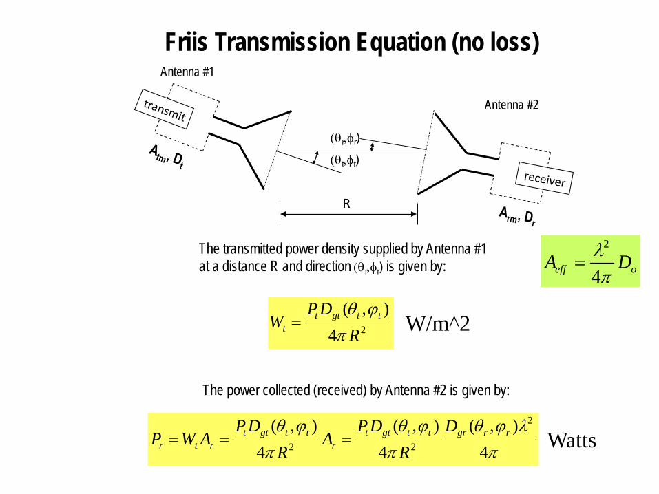
The transmitted power density supplied by Antenna #1at a distance R and direction (θr,φr) is given by:
24),(
RDP
W ttgttt π
ϕθ=
(θt,φt)(θr,φr)
The power collected (received) by Antenna #2 is given by:
πλϕθ
πϕθ
πϕθ
4),(
4),(
4),( 2
22rrgrttgtt
rttgtt
rtr
DR
DPA
RDP
AWP ===
W/m^2
Watts
oeff DAπλ4
2
=
Friis Transmission Equation (no loss)
Antenna #2
Antenna #1
R
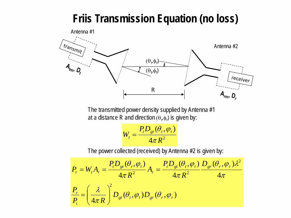
The transmitted power density supplied by Antenna #1at a distance R and direction (θr,φr) is given by:
24),(
RDP
W ttgttt π
ϕθ=
(θt,φt)(θr,φr)
The power collected (received) by Antenna #2 is given by:
),(),(4
4),(
4),(
4),(
2
2
22
rrgrttgtt
r
rrgrttgttr
ttgttrtr
DDRP
P
DR
DPA
RDP
AWP
ϕθϕθπλ
πλϕθ
πϕθ
πϕθ
=
===
Friis Transmission Equation (no loss)
Antenna #2
Antenna #1
R
(θt,φt)(θr,φr)
),(),(4
2
rrgrttgtt
r DDRP
P ϕθϕθπλ
=
If both antennas are pointing in the direction of their maximum radiation pattern:
rotot
r DDRP
P2
4
=
πλ
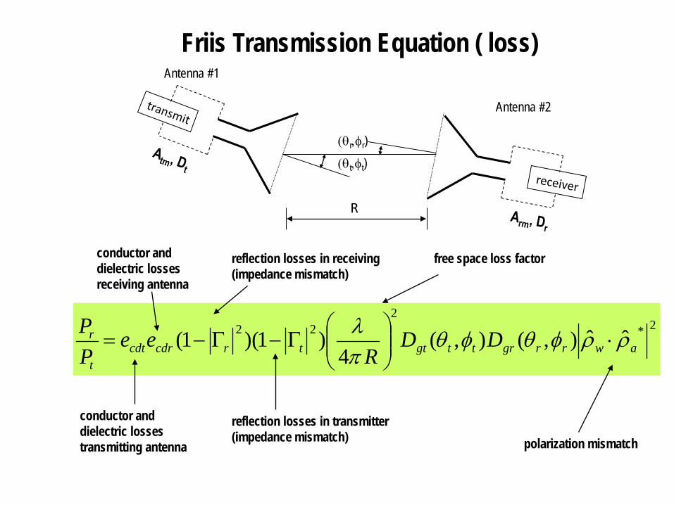
Friis Transmission Equation ( loss)
Antenna #2
Antenna #1
R
(θt,φt)(θr,φr)
2*2
22 ˆˆ),(),(4
)1)(1( awrrgrttgttrcdrcdtt
r DDR
eePP ρρφθφθ
πλ
⋅
Γ−Γ−=
conductor and dielectric lossestransmitting antenna
conductor and dielectric lossesreceiving antenna
reflection losses in transmitter(impedance mismatch)
reflection losses in receiving(impedance mismatch)
polarization mismatch
free space loss factor
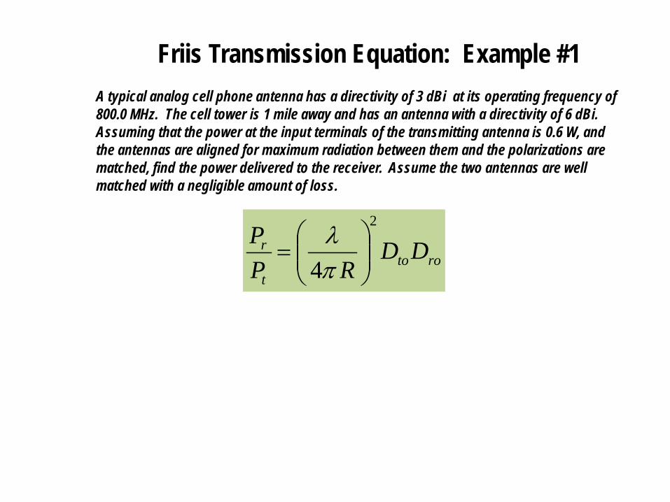
Friis Transmission Equation: Example #1
A typical analog cell phone antenna has a directivity of 3 dBi at its operating frequency of 800.0 MHz. The cell tower is 1 mile away and has an antenna with a directivity of 6 dBi. Assuming that the power at the input terminals of the transmitting antenna is 0.6 W, and the antennas are aligned for maximum radiation between them and the polarizations are matched, find the power delivered to the receiver. Assume the two antennas are well matched with a negligible amount of loss.
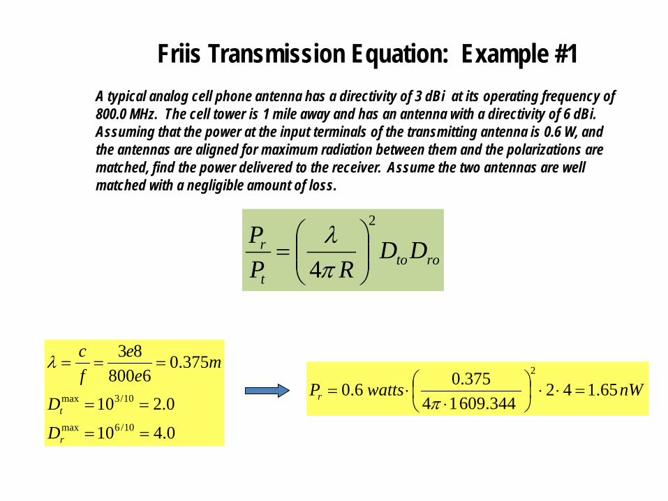
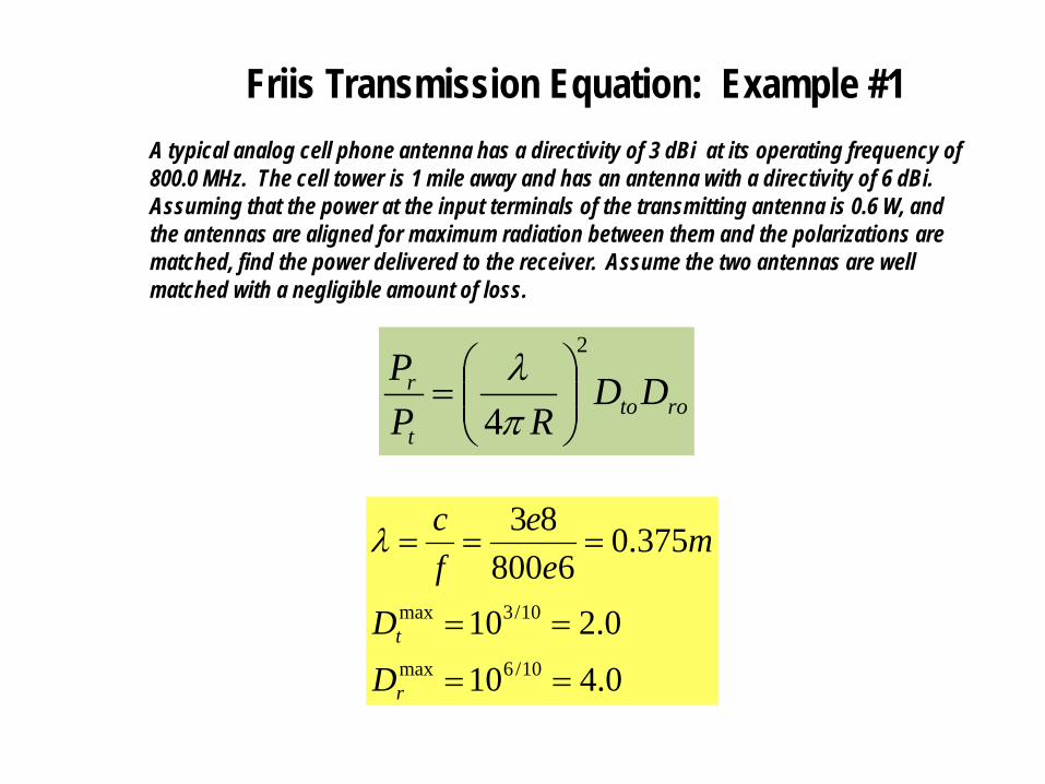
Friis Transmission Equation: Example #1A typical analog cell phone antenna has a directivity of 3 dBi at its operating frequency of 800.0 MHz. The cell tower is 1 mile away and has an antenna with a directivity of 6 dBi. Assuming that the power at the input terminals of the transmitting antenna is 0.6 W, and the antennas are aligned for maximum radiation between them and the polarizations are matched, find the power delivered to the receiver. Assume the two antennas are well matched with a negligible amount of loss.
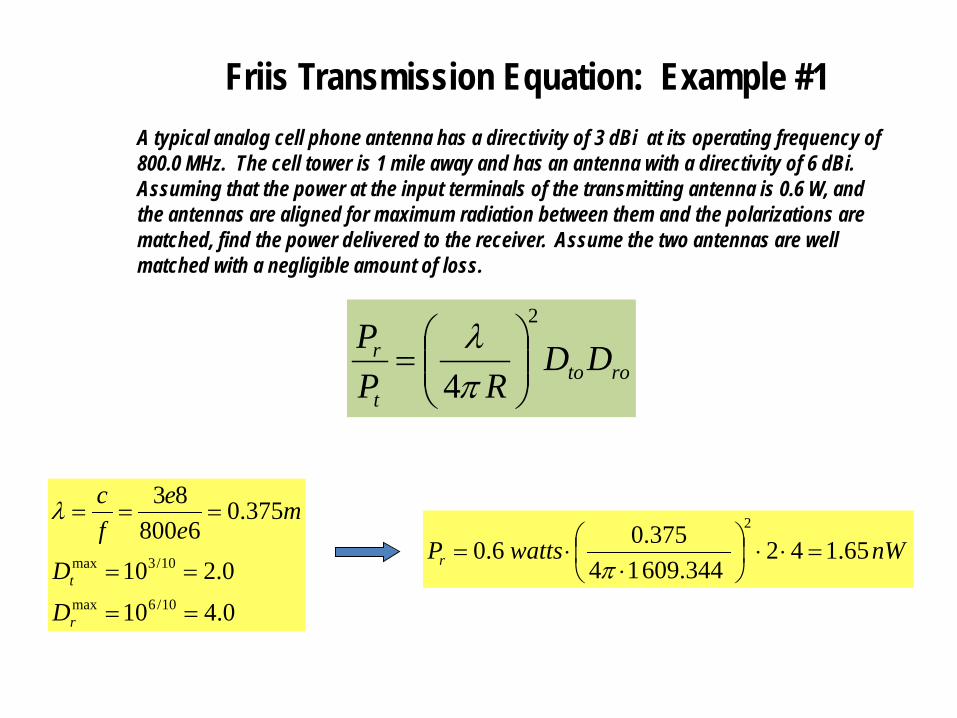
nWwattsPr 65.142 609.344 14
375.06.02
=⋅⋅
⋅⋅=
π
0.4100.210
375.06800
83
10/6max
10/3max
==
==
===
r
t
DD
me
efcλ
rotot
r DDRP
P2
4
=
πλ
Friis Transmission Equation: Example #1A typical analog cell phone antenna has a directivity of 3 dBi at its operating frequency of 800.0 MHz. The cell tower is 1 mile away and has an antenna with a directivity of 6 dBi. Assuming that the power at the input terminals of the transmitting antenna is 0.6 W, and the antennas are aligned for maximum radiation between them and the polarizations are matched, find the power delivered to the receiver. Assume the two antennas are well matched with a negligible amount of loss.
rotot
r DDRP
P2
4
=
πλ
0.4100.210
375.06800
83
10/6max
10/3max
==
==
===
r
t
DD
me
efcλ
Friis Transmission Equation: Example #1A typical analog cell phone antenna has a directivity of 3 dBi at its operating frequency of 800.0 MHz. The cell tower is 1 mile away and has an antenna with a directivity of 6 dBi. Assuming that the power at the input terminals of the transmitting antenna is 0.6 W, and the antennas are aligned for maximum radiation between them and the polarizations are matched, find the power delivered to the receiver. Assume the two antennas are well matched with a negligible amount of loss.
rotot
r DDRP
P2
4
=
πλ
nWwattsPr 65.142 609.344 14
375.06.02
=⋅⋅
⋅⋅=
π
0.4100.210
375.06800
83
10/6max
10/3max
==
==
===
r
t
DD
me
efcλ
Friis Transmission Equation: Example #2
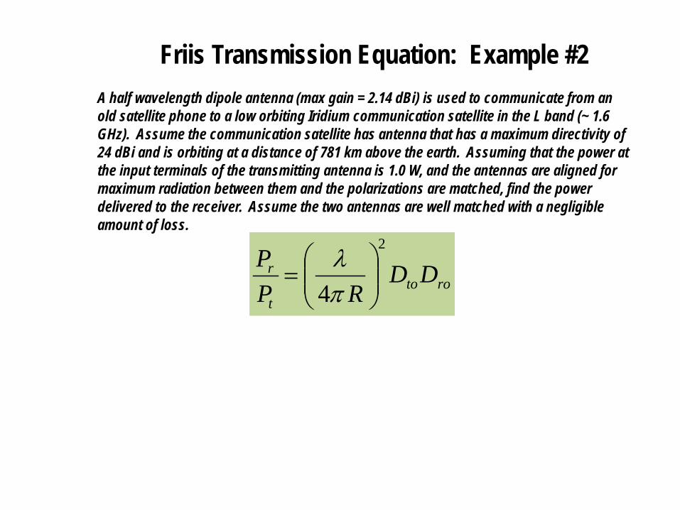
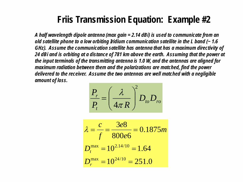
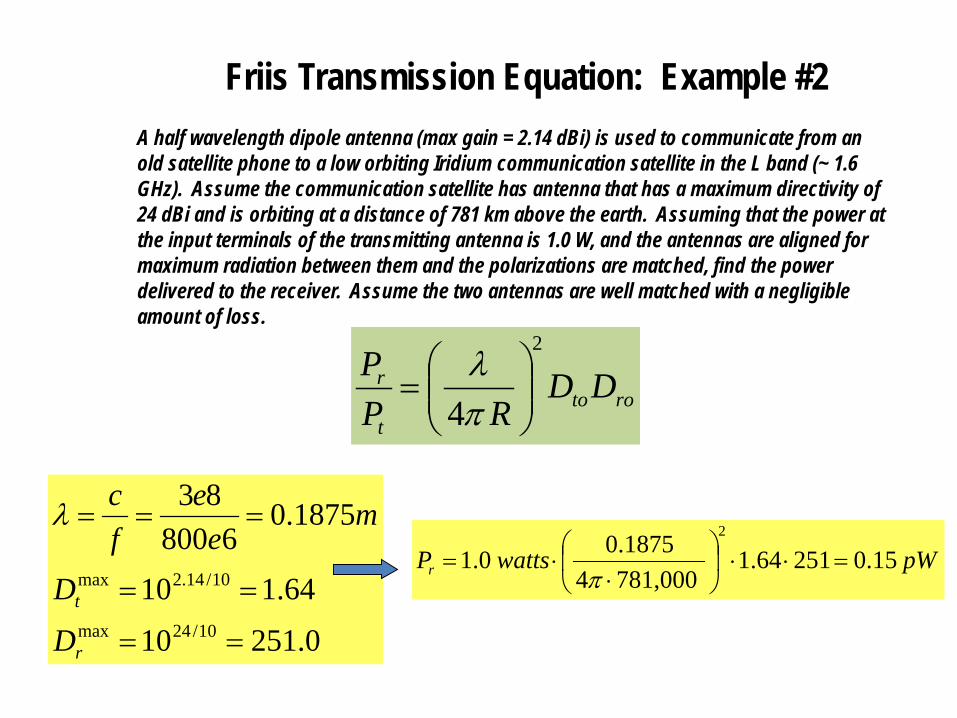
A half wavelength dipole antenna (max gain = 2.14 dBi) is used to communicate from an old satellite phone to a low orbiting Iridium communication satellite in the L band (~ 1.6 GHz). Assume the communication satellite has antenna that has a maximum directivity of 24 dBi and is orbiting at a distance of 781 km above the earth. Assuming that the power at the input terminals of the transmitting antenna is 1.0 W, and the antennas are aligned for maximum radiation between them and the polarizations are matched, find the power delivered to the receiver. Assume the two antennas are well matched with a negligible amount of loss.
Friis Transmission Equation: Example #2A half wavelength dipole antenna (max gain = 2.14 dBi) is used to communicate from an old satellite phone to a low orbiting Iridium communication satellite in the L band (~ 1.6 GHz). Assume the communication satellite has antenna that has a maximum directivity of 24 dBi and is orbiting at a distance of 781 km above the earth. Assuming that the power at the input terminals of the transmitting antenna is 1.0 W, and the antennas are aligned for maximum radiation between them and the polarizations are matched, find the power delivered to the receiver. Assume the two antennas are well matched with a negligible amount of loss.
rotot
r DDRP
P2
4
=
πλ
0.2511064.110
1875.06800
83
10/24max
10/14.2max
==
==
===
r
t
DD
me
efcλ
pWwattsPr 15.025164.1 781,0004
1875.00.12
=⋅⋅
⋅
⋅=π
Friis Transmission Equation: Example #3
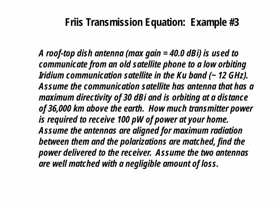
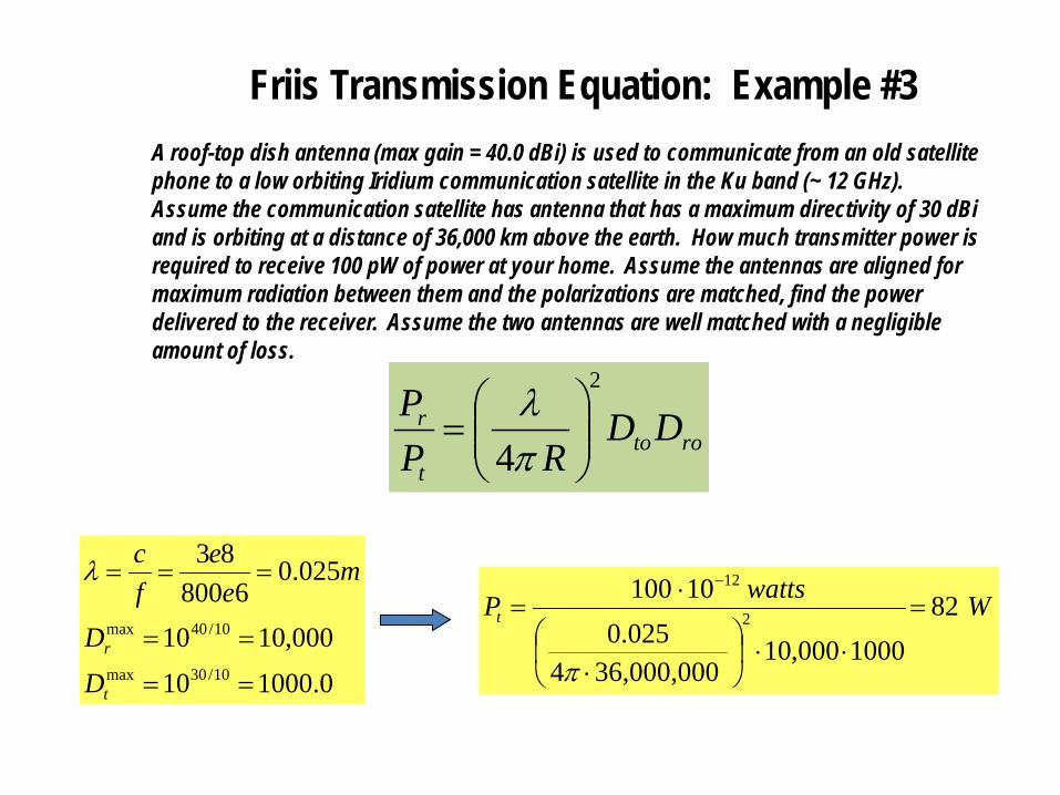
A roof-top dish antenna (max gain = 40.0 dBi) is used to communicate from an old satellite phone to a low orbiting Iridium communication satellite in the Ku band (~ 12 GHz). Assume the communication satellite has antenna that has a maximum directivity of 30 dBi and is orbiting at a distance of 36,000 km above the earth. How much transmitter power is required to receive 100 pW of power at your home. Assume the antennas are aligned for maximum radiation between them and the polarizations are matched, find the power delivered to the receiver. Assume the two antennas are well matched with a negligible amount of loss.
Friis Transmission Equation: Example #3A roof-top dish antenna (max gain = 40.0 dBi) is used to communicate from an old satellite phone to a low orbiting Iridium communication satellite in the Ku band (~ 12 GHz). Assume the communication satellite has antenna that has a maximum directivity of 30 dBi and is orbiting at a distance of 36,000 km above the earth. How much transmitter power is required to receive 100 pW of power at your home. Assume the antennas are aligned for maximum radiation between them and the polarizations are matched, find the power delivered to the receiver. Assume the two antennas are well matched with a negligible amount of loss.
WwattsPt 821000000,10
36,000,0004025.0
101002
12
=
⋅⋅
⋅
⋅=
−
π0.100010000,1010
025.06800
83
10/30max
10/40max
==
==
===
t
r
DD
me
efcλ
rotot
r DDRP
P2
4
=
πλ
Radar Range Equation
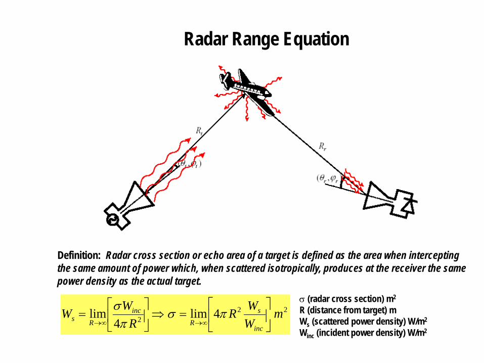
Definition: Radar cross section or echo area of a target is defined as the area when interceptingthe same amount of power which, when scattered isotropically, produces at the receiver the samepower density as the actual target.
222 4lim
4lim m
WWR
RWW
inc
s
R
inc
Rs
=⇒
=
∞→∞→πσ
πσ σ (radar cross section) m2
R (distance from target) mWs (scattered power density) W/m2
Winc (incident power density) W/m2
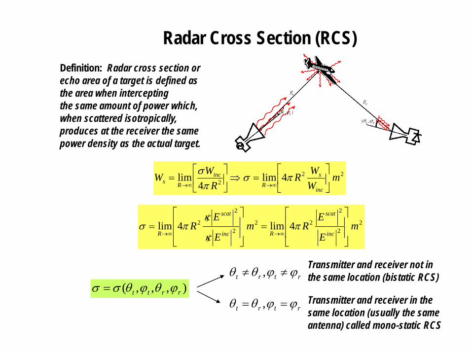
Radar Cross Section (RCS)Definition: Radar cross section or echo area of a target is defined as the area when interceptingthe same amount of power which, when scattered isotropically, produces at the receiver the samepower density as the actual target.
222 4lim
4lim m
WWR
RWW
inc
s
R
inc
Rs
=⇒
=
∞→∞→πσ
πσ
22
2
222
2
2 4lim4lim mE
ERm
E
ER
inc
scat
Rinc
scat
R
=
/
/=
∞→∞→π
κ
κπσ
),,,( rrtt ϕθϕθσσ =rtrt ϕϕθθ ≠≠ , Transmitter and receiver not in
the same location (bistatic RCS)
rtrt ϕϕθθ == , Transmitter and receiver in the same location (usually the same antenna) called mono-static RCS
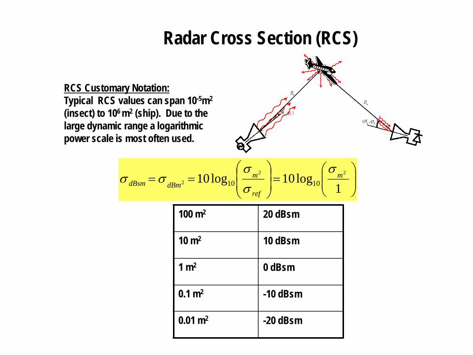
Radar Cross Section (RCS)
RCS Customary Notation: Typical RCS values can span 10-5m2
(insect) to 106 m2 (ship). Due to thelarge dynamic range a logarithmic power scale is most often used.
=
==
1log10log10 22
2 1010m
ref
mdBmdBsm
σσσ
σσ
100 m2 20 dBsm
10 m2 10 dBsm
1 m2 0 dBsm
0.1 m2 -10 dBsm
0.01 m2 -20 dBsm
Radar Range Equation (no losses)
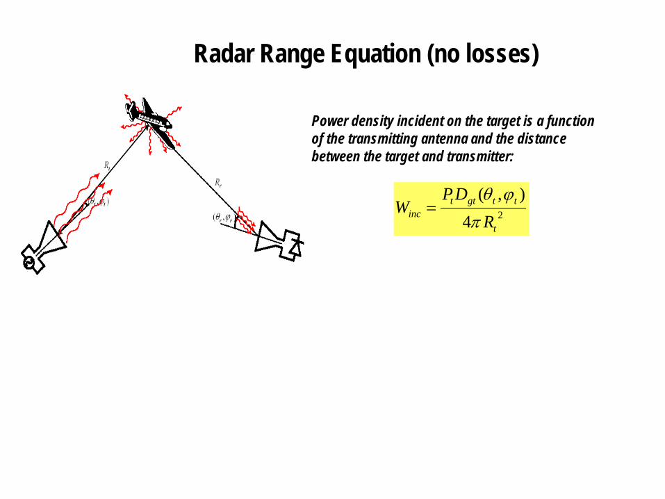
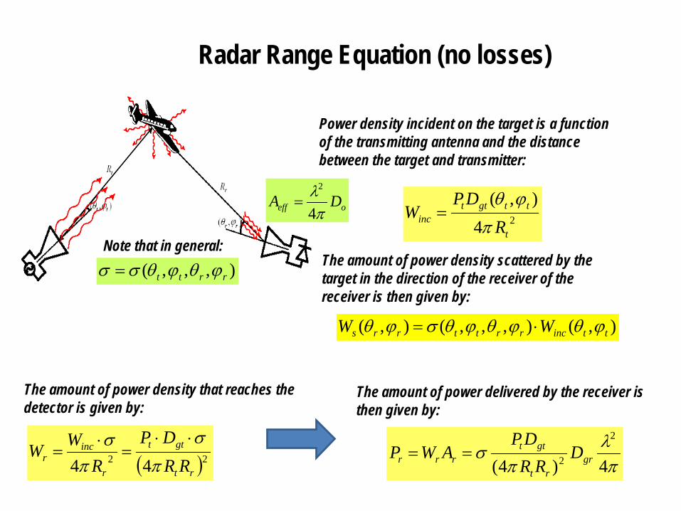
Power density incident on the target is a functionof the transmitting antenna and the distance between the target and transmitter:
24),(
t
ttgttinc R
DPW
πϕθ
=
Radar Range Equation (no losses)
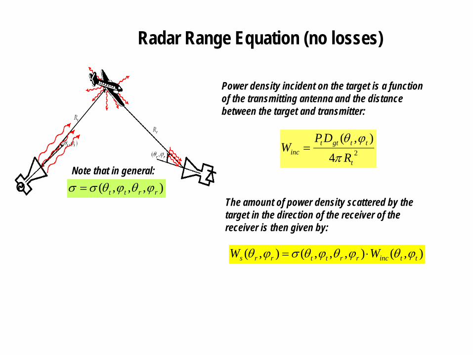
Power density incident on the target is a functionof the transmitting antenna and the distance between the target and transmitter:
24),(
t
ttgttinc R
DPW
πϕθ
=
The amount of power density scattered by the target in the direction of the receiver of the receiver is then given by:
),,,( rrtt ϕθϕθσσ =Note that in general:
),(),,,(),( ttincrrttrrs WW ϕθϕθϕθσϕθ ⋅=
Radar Range Equation (no losses)
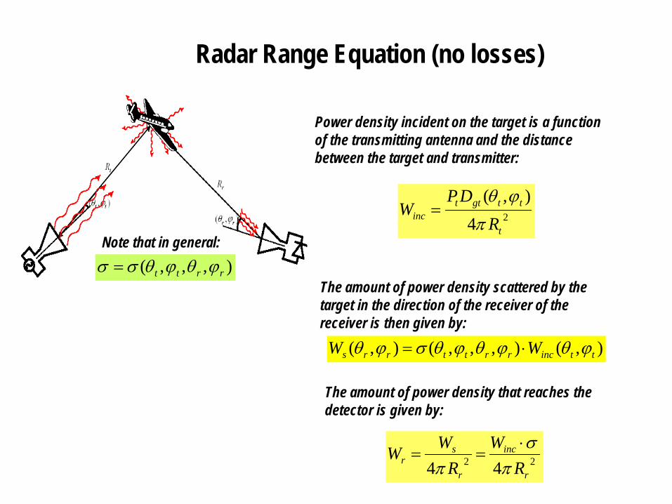
Power density incident on the target is a functionof the transmitting antenna and the distance between the target and transmitter:
24),(
t
ttgttinc R
DPW
πϕθ
=
The amount of power density scattered by the target in the direction of the receiver of the receiver is then given by:
),,,( rrtt ϕθϕθσσ =Note that in general:
),(),,,(),( ttincrrttrrs WW ϕθϕθϕθσϕθ ⋅=
The amount of power density that reaches the detector is given by:
22 44 r
inc
r
sr R
WR
WWπ
σπ
⋅==
Radar Range Equation (no losses)
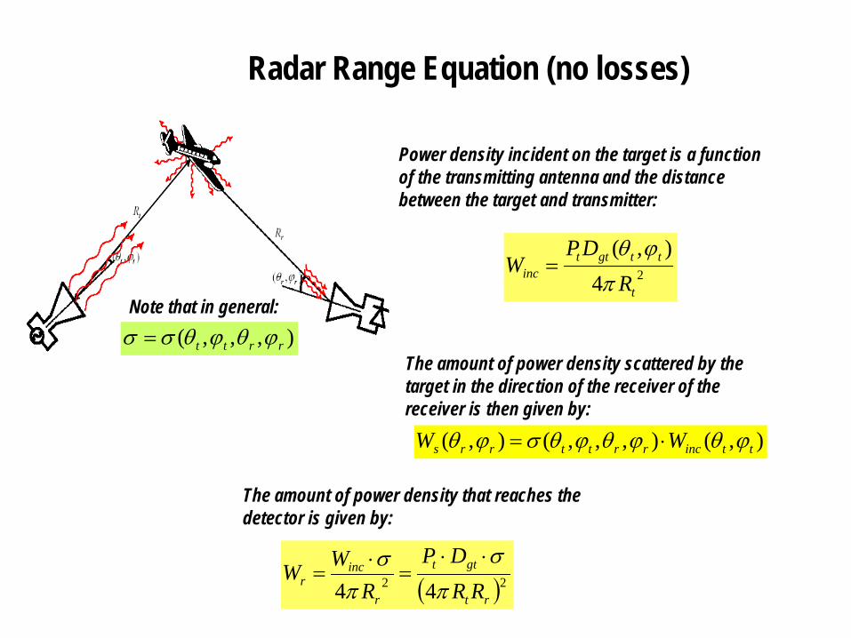
Power density incident on the target is a functionof the transmitting antenna and the distance between the target and transmitter:
24),(
t
ttgttinc R
DPW
πϕθ
=
The amount of power density scattered by the target in the direction of the receiver of the receiver is then given by:
),,,( rrtt ϕθϕθσσ =Note that in general:
),(),,,(),( ttincrrttrrs WW ϕθϕθϕθσϕθ ⋅=
The amount of power density that reaches the detector is given by:
( )22 44 rt
gtt
r
incr RR
DPR
WWπ
σπ
σ ⋅⋅=
⋅=
Radar Range Equation (no losses)
Power density incident on the target is a functionof the transmitting antenna and the distance between the target and transmitter:
24),(
t
ttgttinc R
DPW
πϕθ
=
The amount of power density scattered by the target in the direction of the receiver of the receiver is then given by:
),,,( rrtt ϕθϕθσσ =Note that in general:
),(),,,(),( ttincrrttrrs WW ϕθϕθϕθσϕθ ⋅=
The amount of power density that reaches the detector is given by:
( )22 44 rt
gtt
r
incr RR
DPR
WWπ
σπ
σ ⋅⋅=
⋅=
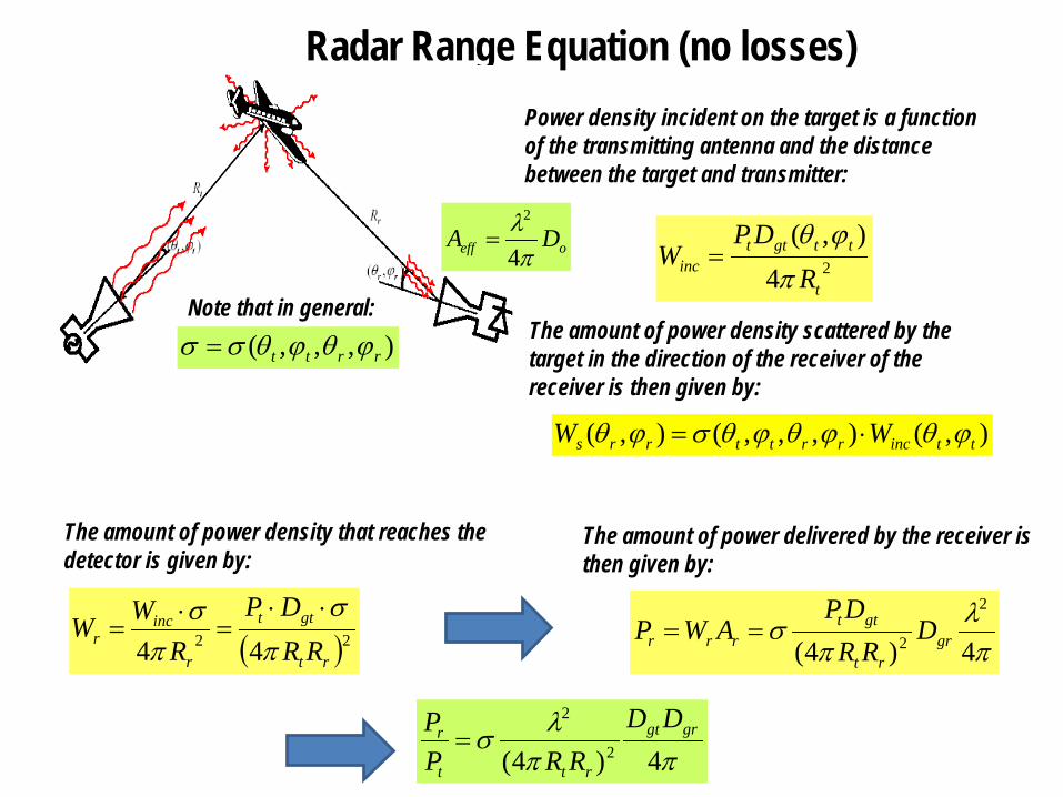
The amount of power delivered by the receiver is then given by:
πλ
πσ
4)4(
2
2 grrt
gttrrr D
RRDP
AWP ==
oeff DAπλ4
2
=
Radar Range Equation (no losses)Power density incident on the target is a functionof the transmitting antenna and the distance between the target and transmitter:
24),(
t
ttgttinc R
DPW
πϕθ
=
The amount of power density scattered by the target in the direction of the receiver of the receiver is then given by:
),,,( rrtt ϕθϕθσσ =Note that in general:
),(),,,(),( ttincrrttrrs WW ϕθϕθϕθσϕθ ⋅=
The amount of power density that reaches the detector is given by:
( )22 44 rt
gtt
r
incr RR
DPR
WWπ
σπ
σ ⋅⋅=
⋅=
The amount of power delivered by the receiver is then given by:
πλ
πσ
4)4(
2
2 grrt
gttrrr D
RRDP
AWP ==
oeff DAπλ4
2
=
ππλσ
4)4( 2
2grgt
rtt
r DDRRP
P=
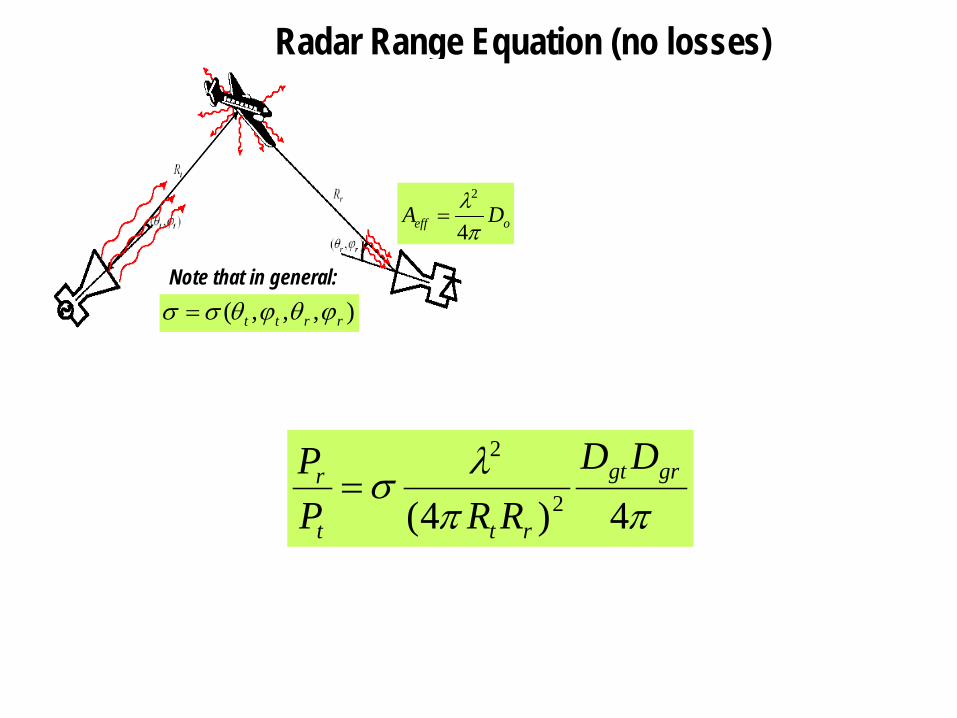
Radar Range Equation (no losses)
),,,( rrtt ϕθϕθσσ =Note that in general:
oeff DAπλ4
2
=
ππλσ
4)4( 2
2grgt
rtt
r DDRRP
P=
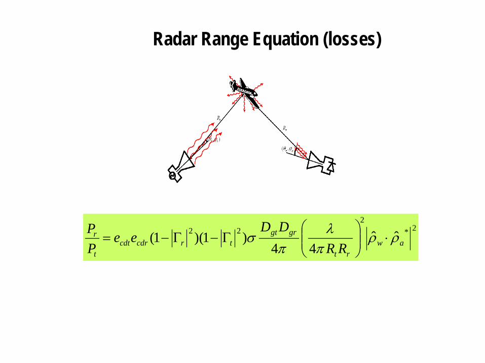
Radar Range Equation (losses)
2*2
22 ˆˆ44
)1)(1( awrt
grgttrcdrcdt
t
r
RRDD
eePP ρρ
πλ
πσ ⋅
Γ−Γ−=