WEY KNIFE GATE VALVES Instruction, Operation and ...
17
1/17 A SISTAG BRAND WEY KNIFE GATE VALVES Instruction, Operation and Maintenance Manual weyvalve.ch | Wey_Knife_Gate_Valve_en weyvalve.ch | Edition: No. 1221-R2 | Date: Dec 23, 2021
Transcript of WEY KNIFE GATE VALVES Instruction, Operation and ...
1 / 1 7 A S ISTAG BRAND
WEY KNIFE GATE VALVES Instruction, Operation and Maintenance Manual
we
yva
lve
.ch
|
W
ey
_K
nif
e_
Ga
te_
Va
lve
_e
n
we
yva
lve
.ch
|
E
dit
ion
: N
o.
122
1-R
2
| D
ate
: D
ec
23
, 2
02
1

WEY KNIFE GATE VALVES | Instruction, Operation and Maintenance Manual
2 / 1 7
1 General
1.1 Safety 1.2 Designated service 1.3 Structure and function
2 Transportation, Storage
2.1 Transportation 2.2 Storage
3 Installation
3.1 Preparation before installation 3.2 Installation site 3.3 Installation position 3.4 Flow and pressure direction 3.5 Mounting 3.6 Valve with cylinder actuator or electric motor 3.7 Welding in line 3.8 Wey Valve suggested flange and body bolt torque
4 Commissioning
4.1 General measures 4.2 Safety measures 4.3 Function Test 4.4 Pneumatically operated valves 4.5 Hydraulically operated valves 4.6 Electrically actuated valves
5 Maintenance
5.1 Inspection 5.2 Operating cycles 5.3 Repacking 5.4 Seal replacement 5.5 Cleaning / Lubrication
6 Trouble Shooting
7 Removal
8 Disposal
9 Warranty
10 Final remarks

WEY KNIFE GATE VALVES | Instruction, Operation and Maintenance Manual
3 / 1 7
1 General
1.1 Safety
Prior to any work or start-up and in order to ensure a proper functioning of our products, the instruction manual
must be observed. Alterations on the products need our written approval. For consequential damages due to
neglect of this direction, we have to reject any liability.
This symbol marks safety and risk advice. Follow all such advice in order to prevent any damage to human life
and objects.
Only qualified personnel are permitted to install Wey valves and must comply with installation and maintenance
procedures in accordance with these instructions. Technical data applicable to Wey Valves, e.g., dimensions,
materials and service range, may be found in this document along with published catalog materials.
The responsibility for compliance with aforementioned documentation remains the sole duty of the end user.
1.2 Designated service
Wey Knife Gate Valves are designed to shut off pressurized piping systems.
Wey Knife Gate Valves may be installed for purpose of dead-end service.
1.3 Structure and function
Figure 1
A Body with seal
B Gate
C Manual actuation
D Pneumatic actuation
E Electrical actuation
F Hydraulic actuation

WEY KNIFE GATE VALVES | Instruction, Operation and Maintenance Manual
4 / 1 7
2 Transportation, Storage
2.1 Transportation
Wey Knife Gate Valves should be transported in crates or well-constructed skids suitable for their weight. The
valve must be protected against exterior damage and atmospheric exposure.
Depending on the duration and conditions of transportation or storage, preservation should take place by
sealing valves into PE-film or adding sufficient drying agent or equal.
2.2 Storage
Until final installation the valves should be stored in a dry, well vented area. Components that provide
operational movement must be suitably protected against humidity, dust or other contamination.
All blank surfaces, e.g., stem, piston rod, sealing surfaces need, to be suitably protected with long-term
preservatives against corrosion, in case of unfavorable storage conditions.
Factory applied preservatives must be checked for possible transport damages and appropriately repaired.
For accessories mounted to the valves, e.g., electric actuators, limit switches, solenoids, etc., the instructions
provided by the manufacturer must be observed.
3 Installation
3.1 Preparation before installation
Before installation, ensure that the Wey Knife Gate Valve satisfies the service condition requirements. The
responsibility regarding applied service medium (corrosion resistance, pressure, temperature, etc.) remains with
the end user. Please check that the valve meets the regulations for the applicable zone, especially when the valve
will be installed in an explosion protected area.
Misaligned piping must be corrected before installation in order to avoid stress or cracking of the valve
body.
Before final installation of the valves any applied corrosion protection must be thoroughly removed. All parts
(gate, stem and piston rod) must be free of dust and dirt.
3.2 Installation site
The valve location and mounting position must be selected to allow inspection and repair at any time without
risk.
For repacking purposes, the narrow edges of the valve body shall be freely accessible.
Additional directives and guidelines for installation and operation of explosion protection equipment must be
observed when installed into Ex-zones.
Check if the equipment fulfills the safety requirements at site.

WEY KNIFE GATE VALVES | Instruction, Operation and Maintenance Manual
5 / 1 7
3.3 Installation position
Wey Knife Gate Valves should be installed in one of the positions shown in Fig. 2. Avoid a different installation
position whenever possible.
Figure 2
Wey Knife Gate Valves from size 16” up with extended or heavy actuators, that are not vertically installed, should
be supported on site. This is also recommended when pipeline vibration may occur.
3.4 Flow and pressure direction
The Wey Knife Gate Valve is based on a bi-directional design (Fig.3). However, depending on certain applications
and valve design options a preferred flow direction must be considered.
Liquid, gaseous and pneumatic conveyed solid fluids
Flow direction Bi-directional possible (A,B)
With the application of a wear ring from the entry side (B)
Pressure direction Against gate bevel preferred (A)
Powder and granulate at gravity discharge (vertical piping)
Flow direction Pressure direction
The gate bevel is positioned on the downstream side, also when a cone insert is used (B)
The preferred pressure direction must especially be considered if the valve is working at 60 – 100% of the
nominal pressure.

WEY KNIFE GATE VALVES | Instruction, Operation and Maintenance Manual
6 / 1 7
Figure 3
1 Gate bevel shape
2 Wear ring (option)
3 Cone insert / contracted bore (option)
For difficult service conditions or for custom-made valves, please contact the manufacturer
regarding the installation position.
3.5 Mounting
Before valve installation, check for possible transportation or storage damages. The valves should be protected
against construction work at site.
For additional painting of the valves, the stem, piston rod, electric accessories and the valve gate protruding
from the body should not be painted. Before any sand blasting, the valves must be protected with covers.
When installing a valve with a stem extension, the pipe flange must be exactly in line with the extension. The
exact position of the flange holes in relation to the extension must also be observed.
Wey Knife Gate Valves are installed between two piping flanges with through bolts and with bolts for blind body
holes.
Piping misalignments should never be corrected using the valve body. Tighten bolts with caution. No tilting,
practice crosswise tightening. See bolt torques charts in chapter 3.8. Apply flange bolts according Fig. 4 into
tapped blind holes.
POS. A POS. B POS. C POS. D
Figure 4
1 2
B A B
1
3

WEY KNIFE GATE VALVES | Instruction, Operation and Maintenance Manual
7 / 1 7
POS. A Wrong assembly. Tightened bolts shall not touch the bottom of the tapped blind holes.
POS. B Correct assembly.
POS. C Also correct assembly. Insert stud, then tighten nut.
POS. D Valve sizes 2”-8” come with tapped through holes in the chest area. Make sure to use the correct
screw length. Under no circumstances can the machine screws in the chest area be allowed to
contact the gate. If contact is made the gate may be damaged and locked in place preventing valve
operation.
Remaining flange holes to be applied with through bolts acc. Fig. 5
Mounting between flanges Mounting as head valve with counter-flange
Figure 5
3.6 Valve with cylinder actuator or electric motor
When cylinder actuated valves or valves with electric motors are mounted in vertical pipes, provisions must be
made to protect the valve from unexpected side loading. This can occur if someone steps on or sits on the
actuator. To protect against this possibility Wey Valve recommends the actuator be supported.
To ensure against side loading or to check this possibility, the clearance between the body and gate on both
sides of the gate can be checked. This clearance should be approximately equal across the full width of the gate
on both sides. This clearance is checked by inserting a machinist’s gauge between the body and gate at the top
of the valve body with the gate in both the closed and open positions.
Consult factory before drilling or tapping any connections to valve and actuator structure. Metal chips must not
be allowed on gate or elsewhere on the entire valve.
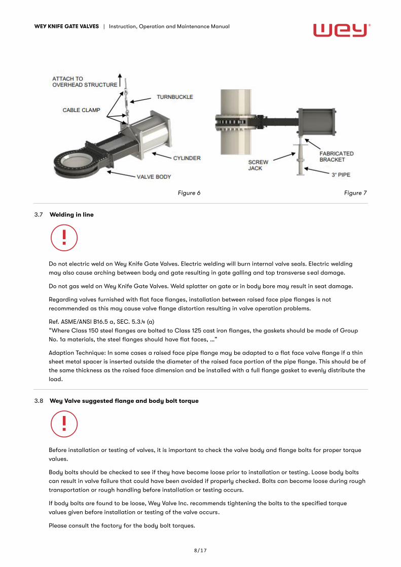
To support the actuator from overhead, use a threaded rod, chain or cable in conjunction with a turnbuckle
attached to the cylinder or electric motor yoke plate. Check gate/body clearance at the top edge of valve body
to ensure proper alignment. (See Fig. 6)
Underneath support is easily achieved using small diameter steel pipe or angle iron with a small jack screw. This
is attached to the valve in the area of the cylinder or electric motor yoke plate. Check gate/body clearance at
the top edge of valve body to ensure proper alignment. (See Fig. 7)
WEY KNIFE GATE VALVES | Instruction, Operation and Maintenance Manual
8 / 1 7
Figure 6 Figure 7
3.7 Welding in line
Do not electric weld on Wey Knife Gate Valves. Electric welding will burn internal valve seals. Electric welding
may also cause arching between body and gate resulting in gate galling and top transverse seal damage.
Do not gas weld on Wey Knife Gate Valves. Weld splatter on gate or in body bore may result in seat damage.
Regarding valves furnished with flat face flanges, installation between raised face pipe flanges is not
recommended as this may cause valve flange distortion resulting in valve operation problems.
Ref. ASME/ANSI B16.5 a, SEC. 5.3.4 (a)
“Where Class 150 steel flanges are bolted to Class 125 cast iron flanges, the gaskets should be made of Group
No. 1a materials, the steel flanges should have flat faces, …”
Adaption Technique: In some cases a raised face pipe flange may be adapted to a flat face valve flange if a thin
sheet metal spacer is inserted outside the diameter of the raised face portion of the pipe flange. This should be of
the same thickness as the raised face dimension and be installed with a full flange gasket to evenly distribute the
load.
3.8 Wey Valve suggested flange and body bolt torque
Before installation or testing of valves, it is important to check the valve body and flange bolts for proper torque
values.
Body bolts should be checked to see if they have become loose prior to installation or testing. Loose body bolts
can result in valve failure that could have been avoided if properly checked. Bolts can become loose during rough
transportation or rough handling before installation or testing occurs.
If body bolts are found to be loose, Wey Valve Inc. recommends tightening the bolts to the specified torque
values given before installation or testing of the valve occurs.
Please consult the factory for the body bolt torques.

WEY KNIFE GATE VALVES | Instruction, Operation and Maintenance Manual
9 / 1 7
During valve installation, it is important to check for proper torque values on the flange bolts. Improper
tightening of these bolts can cause severe damage to the valve and other associated components.
Bolts that are over the recommend torque can cause damage to the threads of the valve and to the valve body;
this could lead to valve failure and leaks.
If flange bolts are not tightened enough, there can be leakage between the valve and flange; which could cause
harm to workers or the environment.
Flange Bolt Torques – ANSI Class 150 Valves
Remarks:
– The flange bolt torques above are suggested values from Sistag/Wey Valve and must not be exceeded
Valve Size Flange Bolt Size Bolt Torque
[mm]
[inch]
UNC / 8-UN [inch]
MA [Nm]
MA [lbf.ft]
50 2" 5/8" 45 35
80 3" 5/8" 85 65
100 4" 5/8" 65 50
150 6" 3/4" 125 90
200 8" 3/4" 175 125
250 10" 7/8" 160 120
300 12" 7/8" 195 140
350 14" 1" 235 175
400 16" 1" 235 175
450 18" 1 1/8" 345 255
500 20" 1 1/8" 305 225
600 24" 1 1/4" 395 290
650 26" 1 1/4" 870 640
700 28" 1 1/4" 860 635
750 30" 1 1/4" 850 630
900 36" 1 1/2" 1470 1085
1050 42" 1 1/2" 845 625
1200 48" 1 1/2" 840 620

WEY KNIFE GATE VALVES | Instruction, Operation and Maintenance Manual
1 0 / 1 7
Flange Bolt Torques – ANSI Class 300 Valves
Remarks:
– The flange bolt torques above are suggested values from Sistag/Wey Valve and must not be exceeded
4 Commissioning
4.1 General measures
Before taking the valves into service, all function relevant parts (gate, stem, piston rod, etc.) shall be thoroughly
cleaned. Damages, in particular to the seal caused by remains of grit, welding beads, foreign rust or similar on
the gate, are not covered by the warranty.
For powder or granular service, it should be observed that wetted or humid media which has tendency to cake to
the gate is thoroughly removed before start-up.
The Wey Knife Gate Valves are factory preserved and lubricated for transportation and storage, but they require
depending on the service conditions, another lubrication before start-up. Recommended are water-repellent,
temperature resistant and long lasting lubricants. (Get your nearest supplier’s recommendation).
4.2 Safety measures
For automated valves installed in an area where valve movement could be dangerous for people (or
animals/objects), it must be ensured by the user on-site that all moving parts are fenced with a suitable cover or
protection shield.
Valve Size Flange Bolt Size Bolt Torque
[mm]
[inch]
UNC / 8-UN [inch]
MA [Nm]
MA [lbf.ft]
50 2" 5/8" 25 15
80 3" 3/4" 50 40
100 4" 3/4" 75 55
150 6" 3/4" 85 60
200 8" 7/8" 135 100
250 10" 1" 135 100
300 12" 1 1/8" 185 135
350 14" 1 1/8" 160 120
400 16" 1 1/4" 235 170
450 18" 1 1/4" 250 185
500 20" 1 1/4" 280 205
600 24" 1 1/2" 385 285
650 26" 1 5/8" 675 495
700 28" 1 5/8" 725 535
750 30" 1 3/4" 890 655
900 36" 2" 1190 880
1050 42" 1 5/8" 725 535
1200 48" 1 7/8" 1120 825
WEY KNIFE GATE VALVES | Instruction, Operation and Maintenance Manual
1 1 / 1 7
Should they not already be mounted, such covers are optionally available from manufacturer. Protection goals
can also be reached through suitable on-site measure. Unprotected valves must not be commissioned.
If hot gases or fluids are transported in the pipeline, ensure that no persons can touch the hot surfaces.
It is also to ensure that no external interference of the control circuits can actuate the valve unintentionally.
4.3 Function Test
Before commissioning, a function test must be performed. Open and close the valve one time as a minimum.
If the pipeline is pressure tested, it is to ensure that the applied pressure is not higher than the maximum allowed
test pressure of the valve.
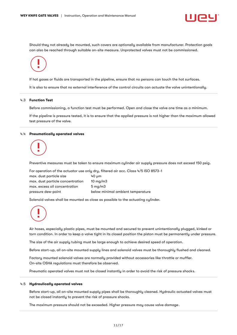
4.4 Pneumatically operated valves
Preventive measures must be taken to ensure maximum cylinder air supply pressure does not exceed 150 psig.
For operation of the actuator use only dry, filtered air acc. Class 4/5 ISO 8573-1
max. dust particle size 40 µm
max. dust particle concentration 10 mg/m3
max. excess oil concentration 5 mg/m3
pressure dew-point below minimal ambient temperature
Solenoid valves shall be mounted as close as possible to the actuating cylinder.
Air hoses, especially plastic pipes, must be mounted and secured to prevent unintentionally plugged, kinked or
torn condition. In order to keep a valve tight in its closed position the piston must be permanently under pressure.
The size of the air supply tubing must be large enough to achieve desired speed of operation.
Before start-up, all on-site mounted supply lines and solenoid valves must be thoroughly flushed and cleaned.
Factory mounted solenoid valves are normally provided without accessories like throttle or muffler.
On-site OSHA regulations must therefore be observed.
Pneumatic operated valves must not be closed instantly in order to avoid the risk of pressure shocks.
4.5 Hydraulically operated valves
Before start-up, all on-site mounted supply pipes shall be thoroughly cleaned. Hydraulic actuated valves must
not be closed instantly to prevent the risk of pressure shocks.
The maximum pressure should not be exceeded. Higher pressure may cause valve damage.
WEY KNIFE GATE VALVES | Instruction, Operation and Maintenance Manual
1 2 / 1 7
4.6 Electrically actuated valves
For electrical installations observe local rules, standards and directives.
When valve is installed into Ex-zones additional directives and guidelines for installation and operation of
explosion protection equipment must also be observed.
Check if the equipment fulfills the safety requirements at site:
After installation a correct ground connection must be verified. This is normally done through the flange bolt
connection. If this is not the case, a ground wire must be connected to the appropriate terminal clamp.
On-site electric installations must be in accordance with appropriate wiring diagram as provided by the actuator
manufacturer. In addition, the specific operating instructions supplied by the actuator manufacturer must be
observed.
Before the first electrical operation, the valve gate should be set to an intermediate position with the manual
override.
When connecting to the power supply, the phase sequence must be observed.
With wrong phase sequence, limit and torque switches are ineffective.
The switch-off shall be in accordance with our instructions/diagrams, i.e.:
- Switch-off in closing direction: usually by limit switches, by exception with torque
- Switches (for abrasive service applications).
- Switch-off in opening direction: by limit switches only, as the torque switch serves as overload protection
5 Maintenance
Wey Knife Gate Valves generally require very little maintenance. The two most common maintenance
requirements include repacking and seal replacement. Additional packing and replacement seal kits are readily
available from the factory. To order these components you must furnish the factory with the valve serial number.
This serial number may be found stamped on the stainless steel name tag that is attached to the valve yoke.
Repacking instructions are included in section 5.3. Seal replacement instructions can be downloaded on
www.weyvalve.com. Valves may be returned to the factory for complete rebuild and test. For more information
regarding this option, contact Wey Valve, Inc., or your local Wey Valve Sales Representative.
5.1 Inspection
When in operation with dangerous fluids especially, the leak-tightness to atmosphere must be monitored on a
regular basis. Valve should be repacked when leakage is detected.
5.2 Operating cycles
During the first year of service at least four (4) operating cycles must be performed at which time all components
should be checked. Under severe service conditions, such functional checks should take place more frequently .
WEY KNIFE GATE VALVES | Instruction, Operation and Maintenance Manual
1 3 / 1 7
5.3 Repacking
With time and use, leakage out of the top of the valve can be expected. This can easily be corrected while the
valve is in the pipeline and under pressure by following the simple steps noted below.
While Wey Knife Gate Valves can generally be repacked while in service and under pressure special precautions
should be taken if the pipe fluid is hot or hazardous. Under these conditions protective clothing including the
hands, eyes and face should be worn prior to any attempt to remove the packing screws. Also, under these
conditions, the packing screws should be removed slowly with the person performing this task immediately alert
to any evidence of leakage past the packing screw. Should leakage past the packing screw be evident it should
be quickly screwed back to its full depth and the system depressurized prior to any further attempt to repack the
valve. If this condition exists, contact Wey Valve for technical assistance.
First: Observe that there are two packing screws located on either side of the valve. Remove the packing screws
slowly and carefully ensuring that there is no hazardous leakage through the two screw holes. NOTE: A simple
repacking tool will be required for this operation. This packing tool can be obtained for a nominal cost from Wey
Valve or easily fabricated on the job site. A piece of drill rod or a round shank screwdriver with the end cut off
works well for this purpose (Tool shaft diameter approx. 3/16” or .187”). The shank length of this tool should be at
least half the diameter of the valve. Care should be taken to sand or grind a slight chamfer on the end of this
tool to prevent screw hole thread damage. Insert the packing tool into the holes and press into packing material
until tight. Sometimes a small rubber or plastic mallet may be used although care must be exercised not to pack
the valve too tightly as this will cause the valve to be difficult to operate. Remove the packing tool.
Second: Insert one packing pellet (approx. 1” length) in holes. Using the packing tool again push each of these
two pellets into the packing chamber as far as they will go. Continue to pack one pellet at a time and alternate
between holes to ensure even packing distribution. It is important this packing procedure does not allow either
face of the gate to come in contact with the inside body wall. Visually check to ensure that approximate equal
clearance is maintained between the gate and body wall throughout this process. Pack both holes until they are
completely filled tightly and no additional packing can be inserted.
Third: Re-install screws.
Fourth: Repeat steps above for screw holes on the other side. If, after following this procedure, a leak persists
out of the top of the valve repeat the repacking procedure using more force to insert the packing pellets. If a
leakage continues to persist it is probably an indication that the transverse seal needs replacing and a new seal
kit should be installed.
NOTE: Sometimes a leak may occur out of the top of a new unused valve. This is usually the result of long term
storage or rough valve transportation. To correct this, simply follow the steps outlined in 1-4 above. To ensure
long term reliability the exterior upper portion of the gate should be kept clean. Threaded stems and thrust
bearings should be kept well greased. Stroke the valve open and closed at least once every two weeks.
WEY KNIFE GATE VALVES | Instruction, Operation and Maintenance Manual
1 4 / 1 7
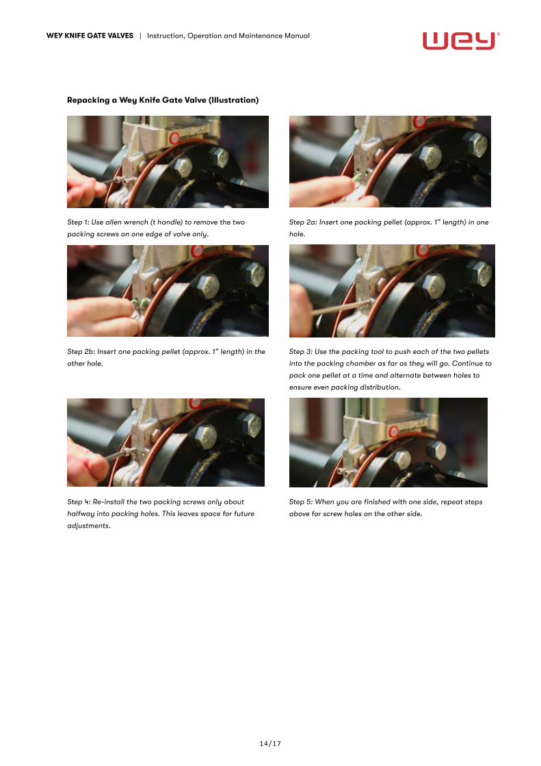
Repacking a Wey Knife Gate Valve (Illustration)
Step 1: Use allen wrench (t handle) to remove the two
packing screws on one edge of valve only.
Step 2a: Insert one packing pellet (approx. 1” length) in one
hole.
Step 2b: Insert one packing pellet (approx. 1” length) in the
other hole.
Step 3: Use the packing tool to push each of the two pellets
into the packing chamber as far as they will go. Continue to
pack one pellet at a time and alternate between holes to
ensure even packing distribution.
Step 4: Re-install the two packing screws only about
halfway into packing holes. This leaves space for future
adjustments.
Step 5: When you are finished with one side, repeat steps
above for screw holes on the other side.
WEY KNIFE GATE VALVES | Instruction, Operation and Maintenance Manual
1 5 / 1 7
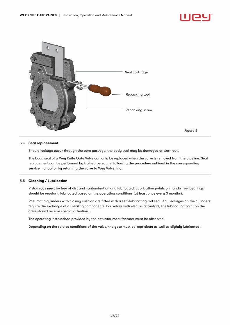
Figure 8
5.4 Seal replacement
Should leakage occur through the bore passage, the body seal may be damaged or worn out.
The body seal of a Wey Knife Gate Valve can only be replaced when the valve is removed from the pipeline. Seal
replacement can be performed by trained personnel following the procedure outlined in the corresponding
service manual or by returning the valve to Wey Valve, Inc.
5.5 Cleaning / Lubrication
Piston rods must be free of dirt and contamination and lubricated. Lubrication points on handwheel bearings
should be regularly lubricated based on the operating conditions (at least once every 3 months).
Pneumatic cylinders with closing cushion are fitted with a self-lubricating rod seal. Any leakages on the cylinders
require the exchange of all sealing components. For valves with electric actuators, the lubrication point on the
drive should receive special attention.
The operating instructions provided by the actuator manufacturer must be observed.
Depending on the service conditions of the valve, the gate must be kept clean as well as slightly lubricated.
Seal cartridge
Repacking tool
Repacking screw
WEY KNIFE GATE VALVES | Instruction, Operation and Maintenance Manual
1 6 / 1 7
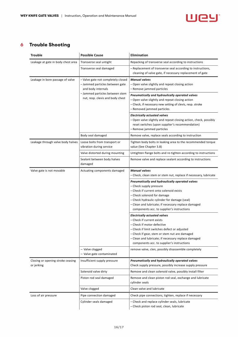
6 Trouble Shooting
Trouble Possible Cause Elimination
Leakage at gate in body chest area Transverse seal untight Repacking of transverse seal according to instructions
Transverse seal damaged – Replacement of transverse seal according to instructions,
cleaning of valve gate, if necessary replacement of gate
Leakage in bore passage of valve – Valve gate not completely closed
– Jammed particles between gate
and body internals
– Jammed particles between stem
nut, resp. clevis and body chest
Manual valves
– Open valve slightly and repeat closing action
– Remove jammed particles
Pneumatically and hydraulically operated valves
– Open valve slightly and repeat closing action
– Check, if necessary new setting of clevis, resp. stroke
– Removed jammed particles
Electrically actuated valves
– Open valve slightly and repeat closing action, check, possibly
reset switches (upon supplier’s recommendation)
– Remove jammed particles
Body seal damaged Remove valve, replace seals according to instruction
Leakage through valve body halves Loose bolts from transport or
vibration during service
Tighten body bolts in leaking area to the recommended torque
value (See Chapter 3.8)
Valve distorted during mounting Untighten flange bolts and re-tighten according to instructions
Sealant between body halves
damaged
Remove valve and replace sealant according to instructions
Valve gate is not movable Actuating components damaged Manual valves
– Check, clean stem or stem nut, replace if necessary, lubricate
Pneumatically and hydraulically operated valves
– Check supply pressure
– Check if current onto solenoid exists
– Check solenoid for damage
– Check hydraulic cylinder for damage (seal)
– Clean and lubricate; if necessary replace damaged
components acc. to supplier’s instructions
Electrically actuated valves
– Check if current exists
– Check if motor defective
– Check if limit switches defect or adjusted
– Check if gear, stem or stem nut are damaged
– Clean and lubricate; if necessary replace damaged
components acc. to supplier’s instructions
– Valve clogged
– Valve gate contaminated
remove valve, clen, possibly disassemble completely
Closing or opening stroke ceasing
or jerking
Insufficient supply pressure Pneumatically and hydraulically operated valves
Check supply pressure, possibly increase supply pressure
Solenoid valve dirty Remove and clean solenoid valve, possibly install filter
Piston rod seal damaged Remove and clean piston rod seal, exchange and lubricate
cylinder seals
Valve clogged Clean valve and lubricate
Loss of air pressure Pipe connection damaged Check pipe connections, tighten, replace if necessary
Cylinder seals damaged – Check and replace cylinder seals, lubricate
– Check piston rod seal, clean, lubricate

WEY KNIFE GATE VALVES | Instruction, Operation and Maintenance Manual
1 7 / 1 7
7 Removal
Use caution when removing the valve from the pipeline. The piping system may be under pressure and therefore
hazardous media may enter into the environment. Precautionary measures must be taken.
Actuators must not be removed if pipe system is under pressure. Electric actuators must be disconnected from
circuit. Pneumatic and hydraulic actuators must be depressurized and disconnected from supply lines. If piping
is removed on one side only, ensure that the valve cannot be operated.
Unintentional opening of the valve can be hazardous to personnel and environment due to drain-off of pipeline
contents. Unintentional closing may be very harmful.
8 Disposal
Observe that sediments inside of valve or pipe can be harmful to people and environment. Respective
precautions measures are to be taken. After finished service life the valve must be disposed ski llful and in
conformity with environmental regulations.
9 Warranty
Wey Valve products are warranted to be free of defects in materials and workmanship, but our liability shall be
limited solely to those defects which are due to our fault and of which we receive notice in writing one year from
the date of shipment. Our liability for breach of warranty will be discharged and satisfied exclusively by
repairing or replacing such defective products upon return to our factory in Shannon, Mississippi, and only if
inspection finds such products to be defective in material or workmanship due to the fault of Wey Valve, Inc.
In no event shall our liability for breach of warranty herein made exceed the price of the product sold by Wey
Valve, Inc., and Wey Valve, Inc., shall not be liable for interruption of operations, labor charges other than those
before mentioned, loss of profits, damages for delays, damages to property, personal injuries or any other
damages, special, specific, direct, incidental, consequential, indirect or otherwise.
The warranty herein is in lieu of all other warranties, express, implied in fact or implied by law and, without
limiting the generality of the foregoing disclaimer, is specifically in lieu of all implied warranties of quality,
merchantability of fitness for purpose.
Note: Any Wey Valve products that are altered or modified in any way will invalidate warranty. Non-compliance
with installation, operation and maintenance instruction will invalidate warranty.
10 Final remarks
All details given herein include the current prevailing knowledge of Wey Valve, Inc. This information in
combination with our technical documentation and information about our products and their range of
applications are generally included but do not supersede acceptable mechanical practice. They are not intended
to ensure particular features of the products nor their suitability for a specific application. Intended quality is
defined within our General Sales Conditions.
For any further information, please contact our Customer Service Department.
Wey Valve, Inc., reserves the right to alter or make changes to this document at any time and without notice.