Westinghouse Proprietary Class 2 · Westinghouse Proprietary Class 2 Report ... 1 INTRODUCTION...
37
Transcript of Westinghouse Proprietary Class 2 · Westinghouse Proprietary Class 2 Report ... 1 INTRODUCTION...


Westinghouse Proprietary Class 2
Report SEW 12-015, rev 1 Page 2 of 37
This document contains proprietary information and is subject to the restrictions on the title page.
CONTENTS
1 INTRODUCTION 4
2 ACTIVITY RELEASE IN CLINK 4
3 METHODOLOGY 5
4 ASSESSMENT OF WHICH SYSTEMS THAT ARE CONTAMINATED 5
5 ESTIMATION OF ACTIVITY IN DIFFERENT SYSTEMS IN CLINK 13 5.1 Estimation of surface contamination in components in contact with radioactive
water 13 5.1.1 Surface activity estimations based on dose rate data 16 5.1.1.1 System 324 and 247 16 5.1.1.2 System 313 16 5.1.1.3 System 311 16 5.1.1.4 System 371 17 5.1.1.5 System 372 17 5.1.1.6 System 373 17 5.1.1.7 System 343 17 5.1.2 Surface activity inventory and nuclide vectors 17 5.1.3 Total activity inventory and specific activity in each system 22 5.1.3.1 Methodology for estimating contaminated surface areas 26 5.2 Estimated activity levels in contaminated concrete 26 5.2.1 Estimated amount of contaminated concrete for the Clink facility 27 5.2.2 Estimated activity levels and nuclide spectra for contaminated concrete 28 5.3 Estimated activity in the ventilation system including dry-handling systems in
Ink 33
6 CONCLUSION AND DISCUSSION 34 6.1 Uncertainties 34 6.1.1 Surfaces in contact with radioactive water 34 6.1.2 Contaminated concrete 35 6.1.3 Dry handling and ventilation 35
7 REFERENCES 36
HISTORY 37

Westinghouse Proprietary Class 2
Report SEW 12-015, rev 1 Page 3 of 37
This document contains proprietary information and is subject to the restrictions on the title page.
ABBREVIATIONS
Clab Intermediate storage for spent nuclear fuel
Clink Combined facility Clab and Ink
DF Decontamination factor
Ink Encapsulation unit
O3 Oskarshamn 3
PSAR Preliminary Safety Assessment Report
SKB Svensk kärnbränslehantering AB

Westinghouse Proprietary Class 2
Report SEW 12-015, rev 1 Page 4 of 37
This document contains proprietary information and is subject to the restrictions on the title page.
1 INTRODUCTION
Clink consists of the intermediate storage for spent nuclear fuel, Clab, and the encapsulation unit, Ink, where the spent fuel will be encapsulated in copper canisters for the final repository. The Clab facility is situated on the Simpevarps peninsula close to the Oskarshamn nuclear power plant. Clab started its operation in 1985 and Ink is planned for start of operation in 2025. Decommissioning of Clink is planned for 2076.
To assess the contribution of Clink to the final repository concerning total activity and amounts of decommissioning waste, the levels of activity and contamination in Clink needs to be studied. This report will describe the activity assessments which will be used as input to the report to SKB concerning decommissioning of Clink.
Contaminated systems where decontamination is assessed to be achievable to meet the requirement for wastes to be “free released” are also described. Systems where no contamination is expected will not be considered in this analysis.
2 ACTIVITY RELEASE IN CLINK
The main activity source that is considered to contribute to the decommissioning waste in Clink is the activity in the fuel crud that can be released from the fuel during its handling and storage time in Clink. The fuel crud consists of activated corrosion products and residues of fission products and actinides from fuel failures. Fission products can also be dissolved from damaged fuel that is handled in Clink, where Cs-137 is assumed to be the dominating fission product and other fission products are considered to be orders of magnitude lower than Cs-137.
The main part of the released crud and released isotopes will be captured in the filters and ion-exchange resins in the different cleaning systems in Clink during operation, but some will deposit on components surfaces which will contribute to the future decommissioning waste of Clink. Due to the high solubility of cesium in water, no cesium is assumed to be deposited on the system surfaces. Note that neutron activation processes are not needed to be considered in Clink due to insignificant neutron flux in the plant compared to a nuclear reactor.
Clink is planned to be decommissioned 30 years after the last spent fuel batch is transferred to Clab. The last reactor planned to be shut-down in Sweden is Oskarshamn 3 (O3), which is planned to close January 2045. The spent fuel can be moved from O3 one year after shutdown, i.e. January 2046 and thus Clink is assumed to be able to be decommissioned in the year 2076. This means that the freshest fuel in Clab will be able to decay for 30 years before Clink is decommissioned.

Westinghouse Proprietary Class 2
Report SEW 12-015, rev 1 Page 5 of 37
This document contains proprietary information and is subject to the restrictions on the title page.
3 METHODOLOGY
To be able to assess the amount and activity of decommissioning waste from Clink, the activity levels and surface contamination in the plant need to be evaluated.
The activity section in PSAR for Clink (chapter 6) presents assessments on levels of activity that is released from the fuel in different systems of Clink and also an estimation of the water activity in the different pools and water-based systems in Clab [1]. However, PSAR does not contain any surface contamination estimations, which are needed in the Clink decommissioning study. To be able to estimate a reasonable surface contamination in the different systems of Clink, different methodologies are used depending on the character of the specific system. The different methodologies used in this report are described under each separate section below covering i) systems in contact with radioactive water, ii) contaminated concrete and iii) ventilation systems and dry-handling in Ink (Section 5.1 to 5.3).
One difficulty that should be noted is that one part of Clink (the encapsulation unit, Ink) has not yet been built so there is of course a greater uncertainty in estimating the activity in this plant since there is no operational experience to base the assessments on. For Clab, there are e.g. surface dose rate measurements and water chemistry measurements from pool water that can be used in the evaluation. Note that the water-based systems in Ink are combined with Clab and the evaluation of these systems can thus rely on operating data from Clab.
4 ASSESSMENT OF WHICH SYSTEMS THAT ARE CONTAMINATED
Systems assessed to be contaminated in Clink are listed in Table 1. In the table, systems that are needed to be deposited in the final repository are described together with systems that are assessed to be able to be decontaminated and the decommissioning waste to be free released. As can be seen in Table 1, most systems are assessed to be able to be decontaminated. A decontamination factor of 10 is assumed. These assessments are based on the assumption that many systems are easily decontaminated and that the released crud is mainly particulate deposits and not as tenacious as for example crud on the fuel surface or from systems operating at higher temperatures. Many of the components in Ink are also assumed to be designed to be easily decontaminated e.g. electro-polished surfaces. Westinghouse experience concerning contamination of tools used in e.g. spent fuel pools at reactors also shows that decontamination of such equipment is feasible. Experience from Studsvik also indicates that particulate contamination when fuel is dry-handled is easily decontaminated [5], [6]. Cleaning of several of the pools in Clab has been performed and has shown that activity levels on the pool surfaces can be considerably reduced by rather simple decontamination.
The following systems need to be considered for the final repository and thus a total activity will be estimated for these systems.

Westinghouse Proprietary Class 2
Report SEW 12-015, rev 1 Page 6 of 37
This document contains proprietary information and is subject to the restrictions on the title page.
• Surface contamination of all systems in contact with radioactive water (311, 313, 324, 371, 372)
• Contaminated concrete in the different pools 151, 152 and 154 (caused by leaks)
• The leak detection system for pools (247)
• Spent resin storage system (373).
• The waste solidification plant (343)
In Ink, only contaminated concrete from system 152 (the pool) and the cooling- and clean-up system (313), which is used for both Clab and Ink, are assessed to be needed to be deposited in the final repository. As can be seen in Table 1, all other systems are assumed to be able to be decontaminated and free released. The handling cell and the fuel drying system (system 255 and 351) in Ink are systems where fuel will be dry-handled and there will thus be a higher risk for contamination from release of crud during the handling. Based on experience from Studsvik [5] and [6], these systems are however assessed to be able to be decontaminated but when operating experience from Ink is available this assumption should be re-evaluated.
Table 1 Systems in Clink assessed to be contaminated and need to be deposited in the final repository and systems where decontamination is assessed to be feasible to free release the waste.
No System Comment Decontamination for free release
Final repository
121 Receiving building (M) Potential risk for contamination if leakage from connecting systems/equipments occurs. If so, it is however assessed that the building construction will be able to be decontaminated by removing contaminated concrete. The small amount of contaminated concrete is assessed to be covered by the uncertainty factor described in Section 0.
x
122 Auxiliary building (H) same as above x 124 Encapsulation building
(A) same as above x
Westinghouse Proprietary Class 2
Report SEW 12-015, rev 1 Page 7 of 37
This document contains proprietary information and is subject to the restrictions on the title page.
No System Comment Decontamination for free release
Final repository
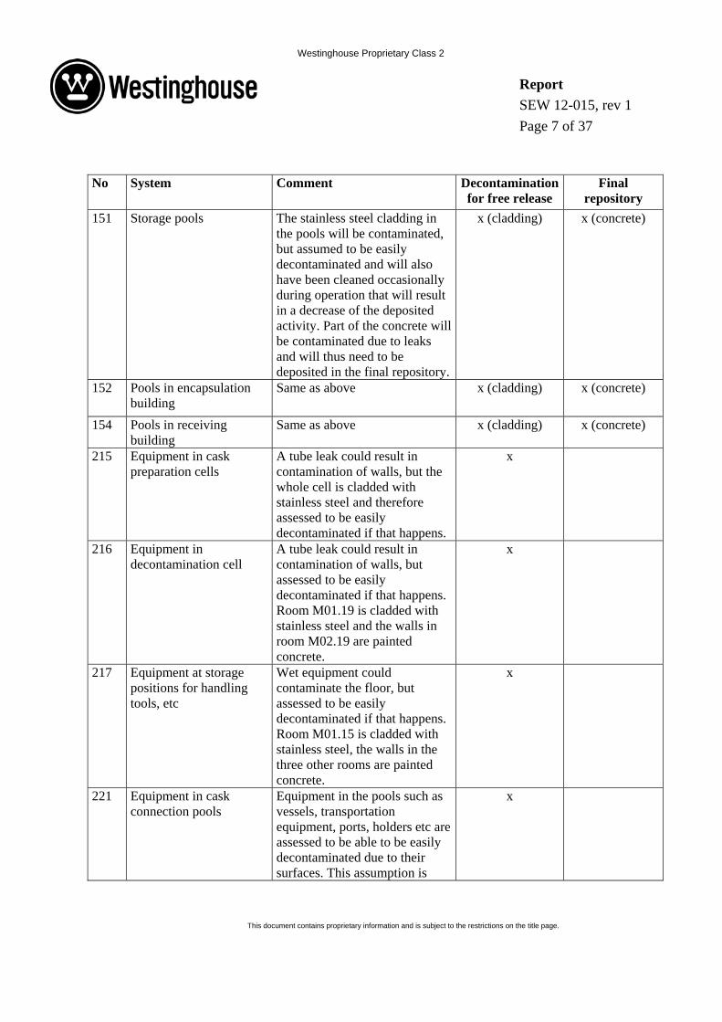
151 Storage pools The stainless steel cladding in the pools will be contaminated, but assumed to be easily decontaminated and will also have been cleaned occasionally during operation that will result in a decrease of the deposited activity. Part of the concrete will be contaminated due to leaks and will thus need to be deposited in the final repository.
x (cladding) x (concrete)
152 Pools in encapsulation building
Same as above x (cladding) x (concrete)
154 Pools in receiving building
Same as above x (cladding) x (concrete)
215 Equipment in cask preparation cells
A tube leak could result in contamination of walls, but the whole cell is cladded with stainless steel and therefore assessed to be easily decontaminated if that happens.
x
216 Equipment in decontamination cell
A tube leak could result in contamination of walls, but assessed to be easily decontaminated if that happens. Room M01.19 is cladded with stainless steel and the walls in room M02.19 are painted concrete.
x
217 Equipment at storage positions for handling tools, etc
Wet equipment could contaminate the floor, but assessed to be easily decontaminated if that happens. Room M01.15 is cladded with stainless steel, the walls in the three other rooms are painted concrete.
x
221 Equipment in cask connection pools
Equipment in the pools such as vessels, transportation equipment, ports, holders etc are assessed to be able to be easily decontaminated due to their surfaces. This assumption is
x

Westinghouse Proprietary Class 2
Report SEW 12-015, rev 1 Page 8 of 37
This document contains proprietary information and is subject to the restrictions on the title page.
No System Comment Decontamination for free release
Final repository
based on experience from cleaning of pool walls in Clab.
222 Equipment in unloading pools
Same as above x
223 Equipment in transfer channel
Same as above x
224 Equipment in pool for storage canisters
Same as above x
226 Equipment in encapsulation building pools
Same as above x
227 Equipment in pool for core components
Same as above x
231 Fuel handling machines in receiving building
Experience from operation of similar equipment in nuclear power plant show that they are possible to decontaminate.
x
232 Fuel handling machine in encapsulation building
Same as above x
233 Fuel elevator The elevator basket is assessed to be able to be decontaminated due to its electro-polished surfaces. The shaft is stainless steel cladded and assessed to be able to be decontaminated.
x
234 Fuel handling machines in storage building
Experience from operation of similar equipment in nuclear power plant show that they are possible to decontaminate.
x
235 Trolley for Transfer Canisters
The equipment has a electro-polished surface, easy to decontaminate.
x
245 Equipment in storage pools
Equipment in the pools such as vessels, transportation equipment, ports, holders etc are assessed to be able to be easily decontaminated due to their
x

Westinghouse Proprietary Class 2
Report SEW 12-015, rev 1 Page 9 of 37
This document contains proprietary information and is subject to the restrictions on the title page.
No System Comment Decontamination for free release
Final repository
surfaces. This assumption is based from experience on cleaning of pool walls in Clab.
247 Leak detection system for pools
The tubes from the leakage control system will be contaminated if a leak occurs. Since they are thin and parts of them are incorporated in the building walls they will be difficult to decontaminate. The container in Clab 1 is however assessed to be able to be decontaminated due to electro-polished surfaces. The container in Clab 2 is assessed to be able to be easily decontaminated due to their surfaces. This assumption is based on experience from cleaning of pool walls in Clab.
x (container) x (tubes)
251 Equipment for measuring the decay heat of spent fuel
Equipment for moving fuel for measurements in the pool, assessed to be easily decontaminated due to the surfaces.
x
253 Fuel service and monitoring equipment
Same as above x
254 Fuel sipping equipment Experience from operation of similar equipment in nuclear power plant show that they are possible to decontaminate.
x

Westinghouse Proprietary Class 2
Report SEW 12-015, rev 1 Page 10 of 37
This document contains proprietary information and is subject to the restrictions on the title page.
No System Comment Decontamination for free release
Final repository
255 Handling cell equipment The floor from entrance position to the drier will be contaminated, but is assessed to be easily decontaminated. The drier and part of the ventilation system will be contaminated by particulate contamination, but electro-polished surfaces could be easily decontaminated.
x
256 Inerting and lidding station equipment
The design of the encapsulation plant is made to avoid contamination after the hot-cell. If contamination occurs, it is assessed that the system could be easily decontaminated.
x
257 Welding station equipment
Same as above x
258 NDT station equipment Same as above x 259 Machining station
equipment Same as above x
267 Handling equipment for solid waste
Same as above x
268 Maintenance casks The container for collecting filter bags from sediment cleaning is assessed to be able to be decontaminated.
x
271 Fuel storage canisters Study shows that this equipment is able to be decontaminated [8].
x
273 Canisters for core components
Same as above x
275 Cans for leaking fuel Same as above x 277 Transfer canisters Same as above x 287 Shielded frames The design of the encapsulation
plant is made to avoid contamination after the hot-cell. If contamination occurs, it is assessed that the system could be easily decontaminated.
x
Westinghouse Proprietary Class 2
Report SEW 12-015, rev 1 Page 11 of 37
This document contains proprietary information and is subject to the restrictions on the title page.
No System Comment Decontamination for free release
Final repository
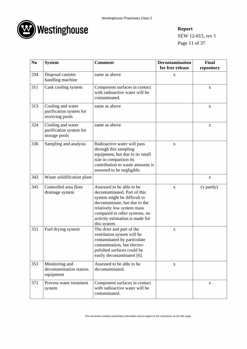
294 Disposal canister handling machine
same as above x
311 Cask cooling system Component surfaces in contact with radioactive water will be contaminated.
x
313 Cooling and water purification system for receiving pools
same as above x
324 Cooling and water purification system for storage pools
same as above x
336 Sampling and analysis Radioactive water will pass through this sampling equipment, but due to its small size in comparison its contribution to waste amounts is assessed to be negligible.
x
343 Waste solidification plant x
345 Controlled area floor drainage system
Assessed to be able to be decontaminated. Part of this system might be difficult to decontaminate, but due to the relatively low system mass compared to other systems, no activity estimation is made for this system.
x (x partly)
351 Fuel drying system The drier and part of the ventilation system will be contaminated by particulate contamination, but electro-polished surfaces could be easily decontaminated [6].
x
353 Monitoring and decontamination station equipment
Assessed to be able to be decontaminated.
x
371 Process water treatment system
Component surfaces in contact with radioactive water will be contaminated.
x

Westinghouse Proprietary Class 2
Report SEW 12-015, rev 1 Page 12 of 37
This document contains proprietary information and is subject to the restrictions on the title page.
No System Comment Decontamination for free release
Final repository
372 Floor drainage water treatment system
Component surfaces in contact with radioactive water will be contaminated. If leaks from vessels occur, concrete under the vessels might be contaminated. This system was initially assessed not to be able to be decontaminated for free release and an activity calculations was been performed for this system which showed that the activity levels after decontamination will be below the limit for free release, see further details in Section 5.1.3.
x
373 Spent resin storage system
Ion exchange resins transported in tubes to the waste solidification plant
x
391 Mobile cooling system If this mobile system is used as replacement for the ordinary cooling cells, they will be contaminated with water from 311. This will however be for a limited time period which will not result in as high surface decontamination as in 311. Assessed to be able to be decontaminated.
x
553 Stack radiation monitoring
The contribution from this equipment to waste amounts is assessed to be negligible.
x
554 Process system radiation monitoring
same as above x
555 Radiation monitoring for certain rooms
same as above x

Westinghouse Proprietary Class 2
Report SEW 12-015, rev 1 Page 13 of 37
This document contains proprietary information and is subject to the restrictions on the title page.
No System Comment Decontamination for free release
Final repository
742.1 Ventilation system for controlled areas in Clab
Surface dose rate measurements of the ventilation in Clab shows levels that at this stage is assessed to be free released. Some parts are contaminated by ion exchange resin, but assumed to be able to be decontaminated.
x
742.2 Ventilation system for controlled areas in Ink
Surface dose rate measurements of the ventilation in Clab shows levels that at this stage is assessed to be free released. This assumption can therefore also be used for the water-based handling in Ink. The ventilation system in Ink, where fuel is dry-handled, is assessed to be able to decontaminated and free released [6].
x
5 ESTIMATION OF ACTIVITY IN DIFFERENT SYSTEMS IN CLINK
5.1 ESTIMATION OF SURFACE CONTAMINATION IN COMPONENTS IN CONTACT WITH RADIOACTIVE WATER
The surface activity levels in the different systems in Clink have been estimated in a separate report [10] and the methodology used in that report is summarized below. Dose rate measurements and gamma spectrometry measurements from Clab have been used to estimate the surface contamination of components in Clink in contact with radioactive water, in combination with weighting with water activities. The dose rate data are taken from measurements on tubes in system 313 and 324 and also from heat exchangers in system 324 [10]. Gamma spectrometry measurements on the tanks in system 373 [9] have been used to develop a relevant weighting factor to estimate surface activity in system 373 based on the surface activity estimations made on system 324.
The measured dose rates can be converted to a deposited surface activity by performing shielding calculations [10]. Both the deposited surface activity and the activity in the water in the specific system are contributing to the measured dose rates, i.e. the measured dose rates are the sum of the deposited surface activity and the activity in the water in the specific system
Westinghouse Proprietary Class 2
Report SEW 12-015, rev 1 Page 14 of 37
This document contains proprietary information and is subject to the restrictions on the title page.
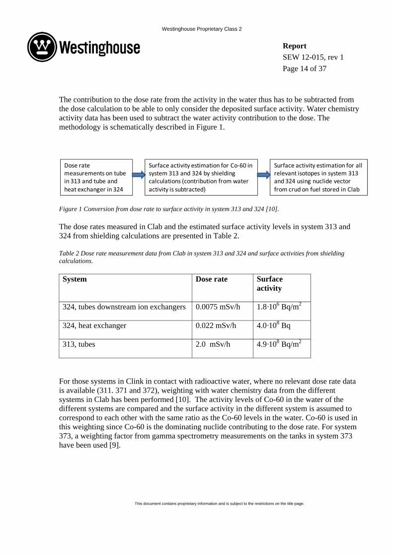
The contribution to the dose rate from the activity in the water thus has to be subtracted from the dose calculation to be able to only consider the deposited surface activity. Water chemistry activity data has been used to subtract the water activity contribution to the dose. The methodology is schematically described in Figure 1.
Figure 1 Conversion from dose rate to surface activity in system 313 and 324 [10].
The dose rates measured in Clab and the estimated surface activity levels in system 313 and 324 from shielding calculations are presented in Table 2.
Table 2 Dose rate measurement data from Clab in system 313 and 324 and surface activities from shielding calculations.
System Dose rate Surface activity
324, tubes downstream ion exchangers 0.0075 mSv/h 1.8·106 Bq/m2
324, heat exchanger 0.022 mSv/h 4.0·108 Bq
313, tubes 2.0 mSv/h 4.9·108 Bq/m2
For those systems in Clink in contact with radioactive water, where no relevant dose rate data is available (311. 371 and 372), weighting with water chemistry data from the different systems in Clab has been performed [10]. The activity levels of Co-60 in the water of the different systems are compared and the surface activity in the different system is assumed to correspond to each other with the same ratio as the Co-60 levels in the water. Co-60 is used in this weighting since Co-60 is the dominating nuclide contributing to the dose rate. For system 373, a weighting factor from gamma spectrometry measurements on the tanks in system 373 have been used [9].
Dose rate measurements on tubein 313 and tube and heat exchanger in 324
Surface activity estimation for Co‐60 in system 313 and 324 by shieldingcalculations (contribution from water activity is subtracted)
Surface activity estimation for all relevant isotopes in system 313 and 324 using nuclide vectorfrom crud on fuel stored in Clab

Westinghouse Proprietary Class 2
Report SEW 12-015, rev 1 Page 15 of 37
This document contains proprietary information and is subject to the restrictions on the title page.
Figure 2 Surface activity in systems 311, 343, 371 and 372 based on data for 313 and 324 and weighting [10]
The rationale for using water activity data for the weighting is that the level of surface contamination can be assumed to be related to the level of water activity in the different systems. The radioactive isotopes in the water will distribute between the water and surfaces by depositing on the components surfaces. The fraction of particulate and soluble radioactive species in the water is also impacting the deposition.
For some systems, the measured water activity in Clab shows that the surface contamination can be assumed to be lower downstream the clean-up filters and ion exchangers. In this study, the higher activity levels upstream filter and ion exchangers will be used to preserve some conservatism.
Most systems in Clink are operated at low temperature and atmospheric pressure compared to reactor systems and the deposition mechanism is therefore different in Clink systems compared to the deposition on reactor surfaces. In hot systems, surface deposition is dominated by buildup of oxides on the surfaces while in colder systems the particle deposition is more pronounced. This can be exemplified by a comparison between system 313 and system 324 (downstream ion exchangers) in Clab where the water activity of Co-60 is comparable but the dose rates are three orders of magnitude higher in system 313 compared to 324 (Table 2). This can be explained by the considerably larger fraction of particulate species in system 313 that has deposited on the surfaces in that system.
A more detailed activity assessment i.e. nuclide specific surface activity measurements are recommended to be performed in some critical components in some of the systems prior to the future decommissioning to get more accurate information about the surface contamination in different system in Clink.
Surface activity data for tube in 313 and tubeand heat exchanger in 324
System 371, 372:Surface activity estimation from system 324 and weighting with water chemistry data
System 311:Surface activity estimation from system 313 and weighting with water chemistry data
System 373:Surface activity estimation from system 324 and weighting factor based on reference [10]
System 343:Surface activity levelassumed to be the same as for tubes in system 373

Westinghouse Proprietary Class 2
Report SEW 12-015, rev 1 Page 16 of 37
This document contains proprietary information and is subject to the restrictions on the title page.
When the estimated surface activity in the different systems in Clab has been determined it can be used to calculate a total activity, using the surface areas of components in contact with water, and also for calculation of specific activity for the different systems using the mass of the components in the system. Decontamination of the water-based systems in Clink is planned both using mechanical cleaning and chemical processes. A decontamination factor (DF) of 10 will be used in the study based on experience from decontamination efforts in operating plants [11]. The DF could probably be higher in reality since the deposits in the systems are mainly loose particulate deposits that would be easily removed.
5.1.1 Surface activity estimations based on dose rate data
The calculated surface activities for system 313 and 324 are used to estimate the surface activities in system 311, 371, 372, 373 and 343 by weighting with water activity data in the different systems. The estimation is described in more detail in [10] and summarized below.
5.1.1.1 System 324 and 247
The surface activity level in tubes downstream ion exchangers and activity in heat exchangers in system 324 is given in Table 2. The surface activity on tubes upstream ion exchangers is assessed to be a factor 100 higher [10]. System 247 is assumed to have the same surface activity level as in system 324 since it is the pool water from system 324 that is passing through system 247.
5.1.1.2 System 313
The surface activity level in tubes in system 313 is given in Table 2. The surface activity in the heat exchanger in system 313 is estimated by using the surface activity for the heat exchanger in system 324 scaled by taking into consideration the difference in effective area for the two heat exchangers.
5.1.1.3 System 311
The surface activity level in system 311 is assumed to be two orders of magnitude higher than in system 313. This is based on water chemistry data comparison between system 311 and 313 which show approximately three orders of magnitude higher activity in system 311 compared to 313 [10]. Since system 311 is only operating when fuel is received to Clab, the weighting factor is assumed to lower than what the water chemistry is indicating and the weighting factor is thus set to 100. The surface activity in the heat exchanger in system 311 is assumed to be the same as on the tubes and the total activity of the heat exchanger can be calculated by using the total heat exchanger area.

Westinghouse Proprietary Class 2
Report SEW 12-015, rev 1 Page 17 of 37
This document contains proprietary information and is subject to the restrictions on the title page.
5.1.1.4 System 371
The water activity level of Co-60 is approximately the same in system 371 and 324 [10] and the surface activity level in system 371 is thus assumed to be the same as in system 324.
5.1.1.5 System 372
The water activity level of Co-60 is approximately a factor of 10 lower in system 372 compared to system and 324 [10] and the surface activity level in system 372 is thus assumed to be a factor of 10 lower than in system 324.
5.1.1.6 System 373
The surface activity level in system 373 is estimated to be a factor 50 higher compared to system 324. This factor is used based on activity measurement performed in system 374 and described in [9]. The ion exchange resins that are stored in the storage vessels in 373 are stored for 20 years and a decay time of 20 years is thus assumed resulting in a lower surface activity in the tubes downstream the storage vessels.
5.1.1.7 System 343
The surface activity level in system 343 is assumed to be the same as in the tubes after the storage vessels in 373 since the tubes from 373 are thereafter connected to system 343.
5.1.2 Surface activity inventory and nuclide vectors
In this study we have assumed that the surface activity estimated based on today’s dose rate measurements are on the same level in 2046 based on the assumption that the build-up and decay of surface deposits is in equilibrium and no major increase in dose rates are assumed until end of operation for Clink1. After 2046, no additional activity contribution from fresh fuel is taking place and only decay will be impacting the activity inventory in Clink. The surface activity levels are thereafter decay corrected to year 2076 to represent the surface activity levels when decommissioning is planned to take place. The nuclide spectra for the different systems are given in Table 3 and Table 4, for the cooling- and cleanup systems and waste handling systems respectively. For some systems where also surface activity data downstream filters or ion exchangers are available, the higher activity levels upstreams will be used in the estimations to preserve some conservatism in the assessment. The relation between the
1 System 311 has shown increasing dose levels and will therefore perform a decontamination campaign to be able to reduce dose levels to personnel. By using dose rate data prior to this decontamination, some conservatism is preserved.

Westinghouse Proprietary Class 2
Report SEW 12-015, rev 1 Page 18 of 37
This document contains proprietary information and is subject to the restrictions on the title page.
different isotopes, before decay correction, is based on the assumed composition in the crud on the fuel to be handled in Clink [10]. The dominating nuclides in the activity inventory at the decommissioning date (year 2076), are Co-60 and Ni-63. Their contribution is 92 % of the total activity.
Table 3 Nuclide spectra for the different cooling- and clean-up systems in Clink, in year 2076 (before decontamination).
Nuclide System 311 Tubes
(Bq/m2)
System 311 Heat
Exchangers (Bq)
System 313 Tubes
(Bq/m2)
System 313 Heat
Exchangers (Bq)
System 324 Tubes
(Bq/m2)
System 324 Heat
Exchangers (Bq)
System 247 Tubes
(Bq/m2)
Mn-54 4.2E-02 4.5E-02 4.2E-04 2.9E-04 1.5E-04 3.4E-04 1.5E-04 Fe-55 1.1E+07 1.2E+07 1.1E+05 7.7E+04 4.1E+04 8.8E+04 4.1E+04 Co-58 1.7E-38 1.8E-38 1.7E-40 1.2E-40 6.2E-41 1.3E-40 6.2E-41 Co-60 4.4E+08 4.8E+08 4.4E+06 3.1E+06 1.6E+06 3.6E+06 1.6E+06 Ni-59 7.4E+06 8.0E+06 7.4E+04 5.2E+04 2.7E+04 5.9E+04 2.7E+04 Ni-63 9.0E+08 9.8E+08 9.0E+06 6.3E+06 3.4E+06 7.3E+06 3.4E+06 Mo-93 4.4E+04 4.8E+04 4.4E+02 3.1E+02 1.6E+02 3.6E+02 1.6E+02
Nb-93m 1.0E+08 1.1E+08 1.0E+06 7.3E+05 3.9E+05 8.4E+05 3.9E+05 Nb-94 3.6E+05 3.9E+05 3.6E+03 2.5E+03 1.3E+03 2.9E+03 1.3E+03 Zr-93 3.1E+04 3.4E+04 3.1E+02 2.2E+02 1.2E+02 2.5E+02 1.2E+02 Tc-99 6.7E+03 7.2E+03 6.7E+01 4.7E+01 2.5E+01 5.4E+01 2.5E+01
Ag-108m 9.5E+05 1.0E+06 9.5E+03 6.6E+03 3.5E+03 7.7E+03 3.5E+03 Ag-110m 6.6E-06 7.2E-06 6.6E-08 4.6E-08 2.5E-08 5.3E-08 2.5E-08 Sb-125 6.0E+04 6.5E+04 6.0E+02 4.2E+02 2.2E+02 4.9E+02 2.2E+02 Ta-182 4.7E-21 5.0E-21 4.7E-23 3.3E-23 1.7E-23 3.8E-23 1.7E-23 Pu-238 6.8E+03 7.4E+03 6.8E+01 4.8E+01 2.5E+01 5.5E+01 2.5E+01 Pu-239 1.2E+03 1.2E+03 1.2E+01 8.1E+00 4.3E+00 9.3E+00 4.3E+00 Pu-240 1.6E+03 1.7E+03 1.6E+01 1.1E+01 5.9E+00 1.3E+01 5.9E+00 Pu-241 3.9E+04 4.3E+04 3.9E+02 2.8E+02 1.5E+02 3.2E+02 1.5E+02 Am-241 1.1E+03 1.2E+03 1.1E+01 8.0E+00 4.2E+00 9.2E+00 4.2E+00 Am-243 9.0E+01 9.8E+01 9.0E-01 6.3E-01 3.4E-01 7.3E-01 3.4E-01 Cm-242 2.3E-19 2.5E-19 2.3E-21 1.6E-21 8.7E-22 1.9E-21 8.7E-22 Cm-244 2.1E+03 2.2E+03 2.1E+01 1.4E+01 7.7E+00 1.7E+01 7.7E+00 Totalt 1.5E+09 1.6E+09 1.5E+07 1.0E+07 5.5E+06 1.2E+07 5.5E+06

Westinghouse Proprietary Class 2
Report SEW 12-015, rev 1 Page 19 of 37
This document contains proprietary information and is subject to the restrictions on the title page.
Table 4 Nuclide spectra for the different waste handling systems in Clink, in year 2076 (before decontamination).
Nuclide System 343 Tubes
(Bq/m2)
System 371 Tubes
(Bq/m2)
System 372 Tubes
(Bq/m2)
System 373 Tubes
(Bq/m2)
Mn-54 7.0E-10 1.5E-04 1.5E-05 7.7E-03 Fe-55 1.2E+04 4.1E+04 4.1E+03 2.0E+06 Co-58 3.3E-70 6.2E-41 6.2E-42 3.1E-39 Co-60 5.9E+06 1.6E+06 1.6E+05 8.2E+07 Ni-59 1.4E+06 2.7E+04 2.7E+03 1.4E+06 Ni-63 1.5E+08 3.4E+06 3.4E+05 1.7E+08 Mo-93 8.2E+03 1.6E+02 1.6E+01 8.2E+03
Nb-93m 8.2E+06 3.9E+05 3.9E+04 1.9E+07 Nb-94 6.6E+04 1.3E+03 1.3E+02 6.7E+04 Zr-93 5.8E+03 1.2E+02 1.2E+01 5.8E+03 Tc-99 1.2E+03 2.5E+01 2.5E+00 1.2E+03
Ag-108m 1.7E+05 3.5E+03 3.5E+02 1.8E+05 Ag-110m 2.3E-15 2.5E-08 2.5E-09 1.2E-06 Sb-125 6.6E+01 2.2E+02 2.2E+01 1.1E+04 Ta-182 5.8E-41 1.7E-23 1.7E-24 8.7E-22 Pu-238 1.2E+03 2.5E+01 2.5E+00 1.3E+03 Pu-239 2.1E+02 4.3E+00 4.3E-01 2.1E+02 Pu-240 2.9E+02 5.9E+00 5.9E-01 2.9E+02 Pu-241 2.8E+03 1.5E+02 1.5E+01 7.3E+03 Am-241 2.1E+02 4.2E+00 4.2E-01 2.1E+02 Am-243 1.7E+01 3.4E-01 3.4E-02 1.7E+01 Cm-242 1.4E-33 8.7E-22 8.7E-23 4.3E-20 Cm-244 1.8E+02 7.7E+00 7.7E-01 3.8E+02 Totalt 1.6E+08 5.5E+06 5.5E+05 2.7E+08
The nuclide vectors (activity related to Co-60) after 30 years of decay in 2076, are given for the cooling- and cleanup systems and waste handling systems in Table 5 and Table 6 respectively.

Westinghouse Proprietary Class 2
Report SEW 12-015, rev 1 Page 20 of 37
This document contains proprietary information and is subject to the restrictions on the title page.
Table 5 Nuclide vectors (related to Co-60) for the different cooling- and clean-up systems in Clink, in year 2076.
Nuclide System 247
System 311
System 313
System 324
System 247
Mn-54 9.4E-11 9.4E-11 9.4E-11 9.4E-11 9.4E-11 Fe-55 2.5E-02 2.5E-02 2.5E-02 2.5E-02 2.5E-02 Co-58 3.8E-47 3.8E-47 3.8E-47 3.8E-47 3.8E-47 Co-60 1.0E+00 1.0E+00 1.0E+00 1.0E+00 1.0E+00 Ni-59 1.7E-02 1.7E-02 1.7E-02 1.7E-02 1.7E-02 Ni-63 2.1E+00 2.1E+00 2.1E+00 2.1E+00 2.1E+00 Mo-93 1.0E-04 1.0E-04 1.0E-04 1.0E-04 1.0E-04
Nb-93m 2.4E-01 2.4E-01 2.4E-01 2.4E-01 2.4E-01 Nb-94 8.1E-04 8.1E-04 8.1E-04 8.1E-04 8.1E-04 Zr-93 7.1E-05 7.1E-05 7.1E-05 7.1E-05 7.1E-05 Tc-99 1.5E-05 1.5E-05 1.5E-05 1.5E-05 1.5E-05
Ag-108m 2.2E-03 2.2E-03 2.2E-03 2.2E-03 2.2E-03 Ag-110m 1.5E-14 1.5E-14 1.5E-14 1.5E-14 1.5E-14 Sb-125 1.4E-04 1.4E-04 1.4E-04 1.4E-04 1.4E-04 Ta-182 1.1E-29 1.1E-29 1.1E-29 1.1E-29 1.1E-29 Pu-238 1.5E-05 1.5E-05 1.5E-05 1.5E-05 1.5E-05 Pu-239 2.6E-06 2.6E-06 2.6E-06 2.6E-06 2.6E-06 Pu-240 3.6E-06 3.6E-06 3.6E-06 3.6E-06 3.6E-06 Pu-241 8.9E-05 8.9E-05 8.9E-05 8.9E-05 8.9E-05 Am-241 2.6E-06 2.6E-06 2.6E-06 2.6E-06 2.6E-06 Am-243 2.1E-07 2.1E-07 2.1E-07 2.1E-07 2.1E-07 Cm-242 5.3E-28 5.3E-28 5.3E-28 5.3E-28 5.3E-28 Cm-244 4.7E-06 4.7E-06 4.7E-06 4.7E-06 4.7E-06

Westinghouse Proprietary Class 2
Report SEW 12-015, rev 1 Page 21 of 37
This document contains proprietary information and is subject to the restrictions on the title page.
Table 6 Nuclide vectors (related to Co-60) for the different waste handling systems in Clink, in year 2076.
Nuclide System 343
System 371
System 372
System 373
Mn-54 1.2E-16 9.4E-11 9.4E-11 9.4E-11 Fe-55 2.0E-03 2.5E-02 2.5E-02 2.5E-02 Co-58 5.6E-77 3.8E-47 3.8E-47 3.8E-47 Co-60 1.0E+00 1.0E+00 1.0E+00 1.0E+00 Ni-59 2.3E-01 1.7E-02 1.7E-02 1.7E-02 Ni-63 2.5E+01 2.1E+00 2.1E+00 2.1E+00 Mo-93 1.4E-03 1.0E-04 1.0E-04 1.0E-04
Nb-93m 1.4E+00 2.4E-01 2.4E-01 2.4E-01 Nb-94 1.1E-02 8.1E-04 8.1E-04 8.1E-04 Zr-93 9.9E-04 7.1E-05 7.1E-05 7.1E-05 Tc-99 2.1E-04 1.5E-05 1.5E-05 1.5E-05
Ag-108m 2.9E-02 2.2E-03 2.2E-03 2.2E-03 Ag-110m 3.9E-22 1.5E-14 1.5E-14 1.5E-14 Sb-125 1.1E-05 1.4E-04 1.4E-04 1.4E-04 Ta-182 9.9E-48 1.1E-29 1.1E-29 1.1E-29 Pu-238 2.0E-04 1.5E-05 1.5E-05 1.5E-05 Pu-239 3.6E-05 2.6E-06 2.6E-06 2.6E-06 Pu-240 5.0E-05 3.6E-06 3.6E-06 3.6E-06 Pu-241 4.7E-04 8.9E-05 8.9E-05 8.9E-05 Am-241 3.5E-05 2.6E-06 2.6E-06 2.6E-06 Am-243 2.8E-06 2.1E-07 2.1E-07 2.1E-07 Cm-242 2.3E-40 5.3E-28 5.3E-28 5.3E-28 Cm-244 3.0E-05 4.7E-06 4.7E-06 4.7E-06
The total surface activity levels in each system at year 2046 and year 2076 is presented in Table 7.

Westinghouse Proprietary Class 2
Report SEW 12-015, rev 1 Page 22 of 37
This document contains proprietary information and is subject to the restrictions on the title page.
Table 7 Total surface activity levels in the different systems in Clink as of year 2046 and decay corrected to year 2076 (for tubes and heat exchangers).
System Activity in year 2046 Decay corrected to year 2076 Tubes
(Bq/m2) Heat Exchangers
(Bq) Tubes
(Bq/m2) Heat Exchangers
(Bq) 247 1.8E+08 5.5E+06
311 4.9E+10 5.3E+10 1.5E+09 1.6E+09 313 4.9E+08 3.0E+09 1.5E+07 1.0E+07 324 1.8E+08 2.3E+08 5.5E+06 1.2E+07 343 5.4E+08 1.6E+08 371 1.8E+08 5.5E+06 372 1.8E+07 5.5E+05 373 9.1E+09 2.7E+08
5.1.3 Total activity inventory and specific activity in each system
The total activity in each system can be calculated by using the total surface activity in Table 7 multiplied with the total surface of each system and a specific activity for each system can thereafter be calculated by dividing the total activity with the total mass of each system. The contribution from valves has been assumed to be negligible in comparison with other components due to their small surface area and weight. The data for all different systems is summarized in Table 8, where also the specific activity is presented including both before and after decontamination. A decontamination factor (DF) of 10 has been assumed.

Westinghouse Proprietary Class 2
Report SEW 12-015, rev 1 Page 23 of 37
This document contains proprietary information and is subject to the restrictions on the title page.
Table 8 Total activity and specific activity for the different systems in Clab in year 2076, contribution from valves assumed negligible
System 372 was initially assessed not to be able to be decontaminated for free release, but the activity calculations presented in Table 8 show activity levels after decontamination below the limit for free release.
Nuclide spectra for the wastes from the different cooling- and clean-up systems and waste handling systems in Clink, in year 2076 (after decontamination) are given in Table 9 and Table 10 and respectively.
System in CLAB
Total System Surface area (m2)
Total System Activity (Bq)
Total system mass (kg)
System Specific activity (Bq/kg)
DF Specific activity after decon (Bq/kg)
Total System Activity after decon (Bq)
247 20 1.1E+08 311 3.5E+05 10 3.5E+04 1.1E+07311 554 7.9E+11 19823 4.0E+07 10 4.0E+06 7.9E+10313 483 6.2E+09 37630 1.6E+05 10 1.6E+04 6.2E+08324 1468 3.2E+09 85789 3.7E+04 10 3.7E+03 3.2E+08343 3 4.6E+08 350 1.3E+06 10 1.3E+05 4.6E+07371 347 1.9E+09 18633 1.0E+05 10 1.0E+04 1.9E+08372 283 1.5E+08 53196 2.8E+03 10 2.8E+02 1.5E+07373 41 1.1E+10 1771 6.3E+06 10 6.3E+05 1.1E+09
Total 3199 8.2E+11 217504 8.2E+10

Westinghouse Proprietary Class 2
Report SEW 12-015, rev 1 Page 24 of 37
This document contains proprietary information and is subject to the restrictions on the title page.
Table 9 Nuclide spectra for the wastes from the different cooling- and clean-up systems in Clink, in year 2076 (before decontamination).
Nuclide System 247 (Bq)
System 311 (Bq)
System 313 (Bq)
System 324 (Bq)
Mn-54 3.0E-04 2.2E+00 1.8E-02 9.1E-03Fe-55 8.0E+04 5.9E+08 4.6E+06 2.4E+06Co-58 1.2E-40 9.0E-37 7.0E-39 3.6E-39Co-60 3.2E+06 2.4E+10 1.9E+08 9.6E+07Ni-59 5.4E+04 4.0E+08 3.1E+06 1.6E+06Ni-63 6.6E+06 4.9E+10 3.8E+08 2.0E+08
Mo-93 3.2E+02 2.4E+06 1.9E+04 9.7E+03Nb-93m 7.6E+05 5.6E+09 4.4E+07 2.3E+07Nb-94 2.6E+03 1.9E+07 1.5E+05 7.8E+04Zr-93 2.3E+02 1.7E+06 1.3E+04 6.8E+03Tc-99 4.9E+01 3.6E+05 2.8E+03 1.5E+03
Ag-108m 6.9E+03 5.1E+07 4.0E+05 2.1E+05Ag-110m 4.8E-08 3.6E-04 2.8E-06 1.4E-06
Sb-125 4.4E+02 3.3E+06 2.5E+04 1.3E+04Ta-182 3.4E-23 2.5E-19 2.0E-21 1.0E-21Pu-238 5.0E+01 3.7E+05 2.9E+03 1.5E+03Pu-239 8.4E+00 6.2E+04 4.9E+02 2.5E+02Pu-240 1.1E+01 8.5E+04 6.6E+02 3.4E+02Pu-241 2.9E+02 2.1E+06 1.7E+04 8.6E+03Am-241 8.3E+00 6.1E+04 4.8E+02 2.5E+02Am-243 6.6E-01 4.9E+03 3.8E+01 2.0E+01Cm-242 1.7E-21 1.3E-17 9.8E-20 5.1E-20Cm-244 1.5E+01 1.1E+05 8.7E+02 4.5E+02Totalt 1.1E+07 7.9E+10 6.2E+08 3.2E+08

Westinghouse Proprietary Class 2
Report SEW 12-015, rev 1 Page 25 of 37
This document contains proprietary information and is subject to the restrictions on the title page.
Table 10 Nuclide spectra for the wastes from the different waste handling systems in Clink, in year 2076 (after decontamination).
The decontamination of the systems in Table 8 will generate waste in form of filters, and possibly also ion exchange resins, which will contain a total activity around 7.4·1011 Bq, if a decontamination factor of 10 is assumed (see the activity estimations in Table 8). The total surface areas for these systems in Clink are approximately 3200 m2.
The decontamination waste in the decommissioning studies from the Swedish nuclear reactors (Barsebäck 1-2) was assessed to result in 7 waste containers with mainly ion exchange resins mixed with cement. The total activity in the decontamination was 2.2·1012 Bq and 3.7·1012 Bq,
Nuclide System 343 (Bq)
System 371 (Bq)
System 372 (Bq)
System 373 (Bq)
Mn-54 2.0E-10 5.4E-03 4.4E-04 3.2E-02Fe-55 3.3E+03 1.4E+06 1.2E+05 8.4E+06Co-58 9.4E-71 2.1E-39 1.8E-40 1.3E-38Co-60 1.7E+06 5.7E+07 4.6E+06 3.4E+08Ni-59 3.9E+05 9.5E+05 7.8E+04 5.6E+06Ni-63 4.2E+07 1.2E+08 9.5E+06 6.9E+08
Mo-93 2.3E+03 5.7E+03 4.7E+02 3.4E+04Nb-93m 2.3E+06 1.3E+07 1.1E+06 8.0E+07Nb-94 1.9E+04 4.6E+04 3.8E+03 2.7E+05Zr-93 1.7E+03 4.1E+03 3.3E+02 2.4E+04Tc-99 3.5E+02 8.7E+02 7.1E+01 5.1E+03
Ag-108m 4.9E+04 1.2E+05 1.0E+04 7.3E+05Ag-110m 6.6E-16 8.5E-07 7.0E-08 5.1E-06
Sb-125 1.9E+01 7.8E+03 6.3E+02 4.6E+04Ta-182 1.7E-41 6.0E-22 4.9E-23 3.6E-21Pu-238 3.3E+02 8.8E+02 7.2E+01 5.2E+03Pu-239 6.1E+01 1.5E+02 1.2E+01 8.8E+02Pu-240 8.3E+01 2.0E+02 1.7E+01 1.2E+03Pu-241 8.0E+02 5.1E+03 4.2E+02 3.0E+04Am-241 5.8E+01 1.5E+02 1.2E+01 8.7E+02Am-243 4.8E+00 1.2E+01 9.5E-01 6.9E+01Cm-242 3.9E-34 3.0E-20 2.4E-21 1.8E-19Cm-244 5.1E+01 2.7E+02 2.2E+01 1.6E+03Totalt 4.6E+07 1.9E+08 1.5E+07 1.1E+09

Westinghouse Proprietary Class 2
Report SEW 12-015, rev 1 Page 26 of 37
This document contains proprietary information and is subject to the restrictions on the title page.
for Barsebäck 1 and 2 respectively and the total area that was decontaminated was 1500 m2 in each reactor.
Since the deposits to be removed from surfaces in Clink are assumed to be mainly particulates, the generated decontamination waste will mainly be filters that would result in smaller waste volumes. The total activity in the decontamination waste is also assessed to be lower in Clink. To preserve some conservatism and to be able to also include additional decontamination waste from systems described in Section 4, the same number of waste containers of decontamination waste is assumed in Clink as for the nuclear reactors. The decontamination waste from Clink is thus estimated to 7 waste containers to be stored in silos in SFR.
5.1.3.1 Methodology for estimating contaminated surface areas
In order to calculate activity inventory, the areas of the contaminated surfaces of the main components was determined. Since no contaminated surface area data was available from Clink, this data was used from Oskarshamn O3 [2]. Linear correlations were set out with the figures from O3 between contaminated surfaces and components weights, for each of the components category of filters, pumps, tanks and heat exchangers. Where the correlation was applicable, contaminated surface areas for Clink could be estimated with the weights of respective component. In those cases where low correlation has been determined a worst-case approach has been used, meaning that the highest ratio of a contaminated surface and component weight has been used in order to calculate contaminated areas.
The respective dimensions of pipes have been available and the contaminated surface areas have consequently been calculated, and no use of correlation has therefore been necessary
5.2 ESTIMATED ACTIVITY LEVELS IN CONTAMINATED CONCRETE
The pools in the Clink facility have stainless steel liners, which protect the concrete structure of being contaminated by direct contact with the pool water. The protective steel liners in the pools in Clab have been shown to be easily decontaminated and will thus be assumed to be free released in this study. However, in case of a leak through the liner it is highly likely that the concrete structure behind it will be contaminated.
The chosen methodology for estimating the amount and activity in contaminated concrete consist of conservatively estimating the amount of leaks in the facility during its operating life and the amount of affected concrete as well as estimating the adsorbed activity into the concrete during this time. This is done by using measured data from Barsebäck and the assumptions used in PSAR [1], [3]. However, there is a lack of data on activity levels in contaminated concrete that has been in contact with radioactive water. Assumptions and

Westinghouse Proprietary Class 2
Report SEW 12-015, rev 1 Page 27 of 37
This document contains proprietary information and is subject to the restrictions on the title page.
extrapolations have thus been used in the activity assessments. Furthermore, some additional conservatism was included by using an uncertainty factor.
5.2.1 Estimated amount of contaminated concrete for the Clink facility
The pools in the Clink facility have stainless steel liners, which protect the concrete structure from being contaminated by direct contact with the pool water. Moreover, behind the liners there is a system of leak testing channels, which will detect leaks and lead away as well as collect the leaked water. The protective steel liners at Clab have been shown to be easily decontaminated and will thus be assumed to be free released in this study. In case of a leak through the liner it is highly likely that the concrete structure behind it will be contaminated. Hence, this part of the study concerns the estimation of the amount and activity of contaminated concrete at the end of operation of the Clink facility. However, it was assumed that it is most unlikely that all pools and channels will have leaks and if such approach would be used it would result in an unnecessary large conservatism.
Based on current knowledge, at least one pool (bottom and one side in storage pool nr 13) have had a leak in Clab during the first 26 years of operation. When taking into account that the expected lifetime of Clab is 85 years, it is possible to estimate by linear extrapolation the total amount of leaks to 3.3. However, it can be argued that the real amount of leaks is higher than the detected amount and/or that an older facility will have more leaks than a new one due to corrosion and wear. Therefore, in order to take into account the possible formation of new leaks or unknown leaks and in order to add additional conservatism to the calculation, an uncertainty factor was introduced. A reasonable value on the uncertainty factor was considered to be 1.5. This would imply that Clab would have 5 leaks at end of operation. In this study it was assumed that 4 normal sized storage pools like pool nr 11 have a leak (assuming that all new leaks appear in an unaffected pool, hence adding further conservatism) plus the storage pool nr 13 that have already been observed to have a leak. In this study the storage pools nr 11-15 are considered to have leaks (Table 11).
The leak detection system behind the liner is not accurate enough to be able to determine the exact surface area that has become contaminated. Hence, in this study it was assumed that for each leak the whole bottom and a whole long side up to the water level are contaminated. This is introducing a considerable amount of conservatism considering the fact that the design of the walls and bottom is done in a way so that the water from a leak on the walls will not be able to spread on the wall and be able to reach the bottom. The water from a leak is directed away and collected in a controlled manner through a system of leak testing channels. Even if the water is able to “jump” one leak channel it is less likely that the water will be able to “jump” a series of channels.
Furthermore, considering the size of the storage pools compared to the other pools and channels in the Clink facility and the introduced conservatism, it is assumed that the estimated

Westinghouse Proprietary Class 2
Report SEW 12-015, rev 1 Page 28 of 37
This document contains proprietary information and is subject to the restrictions on the title page.
amount of contaminated concrete from the 5 leaks in the 5 different storage pools is a good estimate for the total amount of contaminated concrete, at this stage, for the whole Clink facility. The assumptions in this study may be updated or reevaluated once more experience from the Clink facility is gained.
For ease of calculation, it was assumed that the storage pool walls and bottom are all straight and have even surfaces. Furthermore and in accordance with previous decommissioning studies [2], it was assumed that the contamination depth in the concrete is around 1 cm and in order to keep some conservatism, 2 cm will be grinded off for storage in the final repository.
The density used to calculate the mass of the non-reinforced concrete grinded off is set to 2400 kg/m3.
Table 11. Considered measures for storage pools with leaks and the depth of contaminated concrete.
Pool nr
Length (m)
Width (m)
Depth (m)
Contaminated Concrete depth
(m)
Contaminated surface area
(m2)
Contaminated volume (m3)
11 18.2 13.8 12.5 0.02 479 9.6
12 18.2 13.8 12.5 0.02 479 9.6
13 13.8 13.8 12.5 0.02 363 7.3
14 18.2 13.8 12.5 0.02 479 9.6
15 18.2 13.8 12.5 0.02 479 9.6
Total 2279 46
When taken together, the total amount of contaminated concrete from the Clink facility at end of life that will be sent to the final storage is estimated to 110 ton.
5.2.2 Estimated activity levels and nuclide spectra for contaminated concrete
In previous studies of activated and contaminated concrete structures in Barsebäck [3], the main measurements were performed on the biological shield and no reference measurements directly useable for contaminated concrete from the pools in the Clink facility are available.

Westinghouse Proprietary Class 2
Report SEW 12-015, rev 1 Page 29 of 37
This document contains proprietary information and is subject to the restrictions on the title page.
There is, however, one test performed in a sump in the Barsebäck study where the concrete was in contact with radioactive water from the reactor systems. The sump received continuously leakage water during normal operation. The side walls of the sump was not protected by a liner nor painted (only the bottom of the sump was painted). Hence, the water and the concrete were in direct contact. The concrete walls were in contact with considerably higher water activities than what the concrete structure will be in the Clink facility, where contamination may occur due to leaks in the stainless steel liners in the pools. It is considered in this study that the concrete contamination measurement in the sump may be used as a reference in order to estimate the contamination of the concrete structure behind the stainless steel liners in the Clink facility. The levels of activity in the reactor water in Barsebäck and in the water in the pools in Clink (system 324) are in the same order of magnitude when long-term variation is evaluated. The concrete contamination activity levels in the pools in Clab are therefore considered to be comparable to the contamination in the sump in Barsebäck. The source terms for Co-60 and Cs-137 in contaminated concrete that has been used in the decommissioning studies for the Swedish nuclear power plants are based on these Barsebäck data and will thus also be used in the analysis for Clink [4]. The estimated activity per surface area (where the depth of contamination is taken into consideration) was set to 1 MBq/m2 for Co-60 and 0.1 MBq/m2 for Cs-137. The total contaminated concrete surface area (2279 m2, as given in Table 11) thereafter gives the total activity for Cs-137 and Co-60 in the contaminated concrete.
The activity levels for the other reported activated corrosion products and actinides are calculated using the nuclide vector from water activities in system 324 [10]. The nuclide vector from PSAR Table 6-20 are used for the fission products [1].
According to the operational- and decommissioning times described in Section 2, a decay time of 30 years is thereafter applied for the different isotopes, i.e. decommissioning start year 2076. The total activity levels in the contaminated concrete waste are given in Table 12. The resulting isotopic vector for the contaminated concrete after a decay time of 30 years is presented in Table 13. The major contribution to the activity in the concrete after 30 years of decay time originates from Cs-137 (44 %), Ni-63 (35 %), and Co-60 (17 %). These major contributors represent more than 95 % of the total activity in the year 2076.
The following assumptions and/or extrapolations were used in this study:
• The source terms for Co-60 and Cs-137 in contaminated concrete that has been used in the decommissioning studies for the Swedish nuclear power plants [4], which are based on Barsebäck data [3], are used in the analysis for Clink.
• It is most unlikely that all pools and channels in the Clink facility will have leaks. The Clink facility is assessed to have 5 leaks in total at end of operation. This is based on an
Westinghouse Proprietary Class 2
Report SEW 12-015, rev 1 Page 30 of 37
This document contains proprietary information and is subject to the restrictions on the title page.
extrapolation from the amount of leaks in Clab since its start of operation and to the decommissioning data including an uncertainty factor.
• The 5 leaks will occur in 5 different storage pools in Clab.
• For each leak, the whole bottom and a whole long side up to the water level are contaminated.
• The amount of contaminated concrete from the storage pools is conservative and include estimate for the total amount of contaminated concrete for the whole Clink facility.
• The storage pool walls and bottom are all straight and have even surfaces for ease of calculation.
• In accordance with previous decommissioning studies, 2 cm of the concrete will be grinded off for storage in the final repository. The contamination depth in the concrete is around 1 cm and to keep some conservatism, 2 cm is assumed to be grinded off.
• The density for the non-reinforced concrete, that will be grinded off, was assumed to be 2400 kg/m3.
• A decay time of 30 years (related to the estimated shutdown date of O3 and the decommissioning date of the Clink facility i.e. no fresh spent fuel coming in during the last 30 years).

Westinghouse Proprietary Class 2
Report SEW 12-015, rev 1 Page 31 of 37
This document contains proprietary information and is subject to the restrictions on the title page.
Table 12 Estimated levels of activity of different isotopes in the contaminated concrete in 2076 as well as the half-life’s of the different isotopes.
Isotopes Half-life (years)
Activity (Bq), year 2076
Mn-54 8.8E-01 8.2E-03Fe-55 2.7E+00 1.1E+06Co-58 1.9E-01 1.9E-39Co-60 5.3E+00 4.4E+07Ni-59 7.6E+04 7.4E+05Ni-63 1.0E+02 9.1E+07
Mo-93 3.5E+03 4.4E+03Nb-93m 1.6E+01 1.0E+07Nb-94 2.0E+04 3.6E+04Zr-93 1.5E+06 3.1E+03Tc-99 2.1E+05 6.7E+02
Ag-108m 4.2E+02 1.1E+05Ag-110m 6.8E-01 6.7E-07Sb-125 2.8E+00 6.5E+03Ta-182 3.1E-01 4.7E-22Pu-238 8.8E+01 6.8E+02Pu-239 2.4E+04 1.2E+02Pu-240 6.6E+03 2.0E+02Pu-241 1.4E+01 4.0E+03Am-241 4.3E+02 1.1E+02Am-243 7.4E+03 9.1E+00Cm-242 4.5E-01 2.2E-20Cm-244 1.8E+01 2.1E+02
Sr-90 2.9E+01 7.4E+05I-129 1.6E+07 8.7E+01
Cs-134 2.1E+00 1.5E+03Cs-137 3.0E+01 1.1E+08
Total activity 2.6E+08

Westinghouse Proprietary Class 2
Report SEW 12-015, rev 1 Page 32 of 37
This document contains proprietary information and is subject to the restrictions on the title page.
Table 13 Nuclide vector for contaminated concrete at year 2076.
Nuclide Nuclide vector related to Co-60
Mn-54 1.9E-10Fe-55 2.5E-02Co-58 4.3E-47Co-60 1.0E+00Ni-59 1.7E-02Ni-63 2.1E+00
Mo-93 1.0E-04Nb-93m 2.4E-01Nb-94 8.1E-04Zr-93 7.1E-05Tc-99 1.5E-05
Ag-108m 2.4E-03Ag-110m 1.5E-14Sb-125 1.5E-04Ta-182 1.1E-29Pu-238 1.5E-05Pu-239 2.6E-06Pu-240 4.5E-06Pu-241 9.0E-05Am-241 2.6E-06Am-243 2.1E-07Cm-242 5.1E-28Cm-244 4.7E-06
Sr-90 7.3E-06I-129 8.6E-10
Cs-134 1.5E-08Cs-137 1.1E-03

Westinghouse Proprietary Class 2
Report SEW 12-015, rev 1 Page 33 of 37
This document contains proprietary information and is subject to the restrictions on the title page.
5.3 ESTIMATED ACTIVITY IN THE VENTILATION SYSTEM INCLUDING DRY-HANDLING SYSTEMS IN INK
The ventilation system (742) in Ink and Clab has the risk of contamination due to both fuel pool handling in Clab/Ink and the dry handling in Ink.
For estimating the contamination during the dry-handling in Ink and in the ventilation system in Clink, a comparison with experience from the Hot-cell laboratory at Studsvik Nuclear AB was performed [5], [6]. Surface dose rate measurements performed in Clab is also used in the assessment.
Measurements in the ventilation system (system 742) at Clab show that the surface dose rates are generally below 5 μSv/h [7]. A dose rate of 5 μSv/h is assessed to correspond to a surface activity inside the ventilation tube that is slightly higher than the limit for free release. Since the available measured surface dose rate data from Clab is given as a maximum level, some part of the ventilation system could have considerably lower dose rates and could be considered to be free released. In this initial estimation in the decommissioning study, it is thus assessed that the ventilation system in the Clab-part of the Clink could be free released.
There are however, certain parts of the ventilation system where surface dose rates up to 15-20 mSv/h have been measured. These levels correspond to parts of the system where ion exchange resin has accidently entered the ventilation system. If no additional ion exchange resins will enter the ventilation systems, the now existing deposits of resin will decay to considerably lower dose rates (30-40 µSv/h) until year 2076 when decommissioning will take place. Such levels will be easier to handle and decontaminate. In this analysis, these contaminated areas of the ventilation system are assumed to be able to be decontaminated and thereafter free released. If that is really feasible needs to be shown in future studies of these particular areas of the ventilation system.
At the Hot-cell laboratory in Studsvik, spent fuel is handled and examined, also including cutting of the spent fuel rods. This means that the hot cells are occasionally heavily contaminated. Such levels of contamination will not be reached at Ink. Contamination of the ventilation systems is assessed to mainly be caused by the dry handling cells in Ink. The experience from the hot cells at Studsvik [6] shows that it has been possible to decontaminate the ventilation systems, thus it can be assumed that the ventilation systems at Ink can be assessed to be free released after decontamination.
The fuel will be dried in the closed dry-handling cell (system 255) which is directly connected to the ventilation system. The concrete walls in the cell will be covered with protective steel cladding. The experience from the hot-cells in Studsvik shows that is possible to decontaminate the hot cells. This is mainly performed by mechanical cleaning, e.g., vacuum cleaning and wiping. No complex components are assumed in the ventilation system that

Westinghouse Proprietary Class 2
Report SEW 12-015, rev 1 Page 34 of 37
This document contains proprietary information and is subject to the restrictions on the title page.
would be difficult to decontaminate. Since the level of contamination will most likely be lower at Ink than at the Hot-cell laboratory it is assumed that in Ink, the protective steel cladding as well as the concrete behind can be free-released after decontamination.
6 CONCLUSION AND DISCUSSION
The levels of activity and contamination in Clink have been evaluated to be used as input to assess the decommissioning wastes of Clink. Many systems are assumed to be able to be free released after decontamination and only waste from system 247, 311, 313, 324, 371, 373, 343 and contaminated concrete from the pools in 151, 152 and 154 are considered to be deposited in SFR.
The amount and number of waste containers will be evaluated further in Chapter 4 and 6 in the decommissioning study to SKB. The process equipment from the cooling- and clean-up systems in Clink are estimated to contribute with a total activity of 8.2·1010 Bq at decommissioning date and a total of contaminated system mass of 218 ton. The contaminated concrete is estimated to 110 ton of contaminated concrete with a total activity of 2.6·108 Bq at decommissioning, year 2076.
Closer to the decommissioning date, a more refined assessment of activity inventory in the decommissioning waste is recommended. To achieve a more realistic surface contamination inside different components it is recommended that nuclide specific surface activity measurements are performed on critical system surfaces. Below, some of the identified uncertainties in this study are summarized.
6.1 UNCERTAINTIES
The uncertainties in activity inventory are lower for the systems where surface activity calculations has been performed based on measured dose rates in Clab. The uncertainties are higher in the systems in Ink since that plant is not commissioned yet.
6.1.1 Surfaces in contact with radioactive water
• One difficulty that should be noted is that one part of Clink (the encapsulation unit, Ink) has not yet been built so there is of course a greater uncertainty in estimating the activity in this plant since there is no operational experience to base the assessments on.
• The weighting with water activities that has been used for the surface activity assessments in some of the systems where no dose rate data were available is a simplified approach that might contain some uncertainty. The fraction of soluble and particulate fractions in the water is also influencing the weighting assumption.

Westinghouse Proprietary Class 2
Report SEW 12-015, rev 1 Page 35 of 37
This document contains proprietary information and is subject to the restrictions on the title page.
• Since the fraction of particulate species in the water is influencing the deposition on system surfaces to a large extent, any change in these fractions could impact the final surface deposit assumptions.
• The assumption that the release and deposition from system surfaces will be in equilibrium and not increase considerably until year 2046 contains some uncertainty.
• Little is known about changes in crud structure and behavior due to ageing, but a fresher fuel might be considered to result in more mobile crud. For this study, no change due to ageing is assumed which provide some conservatism in the assessment.
6.1.2 Contaminated concrete
The amount of contaminated concrete that has been calculated in this study has the following uncertainties;
• The number of leaks in the pools has been assumed (with some conservatism)
• If leaks from equipment results in contaminated concrete walls, which turns out not to be as easily decontaminated as assessed in this study, the amount of contaminated concrete could be larger.
• Lack of activity measurements of contaminated concrete in contact with water. The reference value from a sump in Barsebäck which has been used for contaminated concrete might not be the most relevant.
6.1.3 Dry handling and ventilation
• Contamination of ion exchange resins in some parts of the ventilation system has been assumed to be able to de decontaminated, but future experience from Clab might give some more detailed assessments if decontamination is feasible or not.
• The assumption to free release system 255, 351 and parts of the ventilation system in Ink contains some uncertainties and is recommended to be revisited when the operating experience from the Ink facility is available.
Westinghouse Proprietary Class 2
Report SEW 12-015, rev 1 Page 36 of 37
This document contains proprietary information and is subject to the restrictions on the title page.
7 REFERENCES
[1] Westinghouse rapport SEP 08-077, rev2, “Clink - PSAR Allmän del Kapitel 6 – Radioaktiva ämnen i anläggningen”, Lars Håkansson, Klas Lundgren, (2009)
[2] Westinghouse rapport SEW 10-141, rev 0”Decomissioning study of Oskarshamn 3”, 2011
[3] Barsebäck rapport 1859289 version 2.0, “B1-Projekt RIVAKT/Aktivitetsbestämning för uttagna borrkärnor av betong”, Lars Håkansson (2005)
[4] ALARA rapport 12-0041R, Revision 0, ”Oskarshamn 3-Aktivitetsinventarium vid rivning”, L Jonasson (2012)
[5] Westinghouse Atom AB rapport SEP 01-314, rev0, ”SVAFO – Rivningsstudier för Studsvikanläggningar Hotcellaboratoriet (HCL)”, 2002
[6] Mikael Karlsson, Studsvik Nuclear AB, private communication
[7] Surface dose rate measurement data from system 742 in Clab provided by Bjarne Andersson (SKB) by e-mail correspondence February 3, 2012.
[8] SKB promemoria DokumentID 1321284, ”Förstudie - Hantering av uttjänta Clab-kassetter”, Anders Eriksson, 2011
[9] Studsvik ALARA Engineering Rapport 12-0059R rev. 0, 2012 ”Clab – Aktivitetsinventarium och strålningsnivåer i system 374”, Jonasson L
[10] Westinghouse rapport SEW 12-104, “Clab – Källstyrkor för strålskärmsdimensionering”, Odd Runevall, 2012
[11] Evaluation of the Decontamination of the Reactor Coolant Systems at Maine Yankee and Connecticut Yankee”, EPRI, Palo Alto, CA: 1999. Report TR-112092

Westinghouse Proprietary Class 2
Report SEW 12-015, rev 1 Page 37 of 37
This document contains proprietary information and is subject to the restrictions on the title page.
History
Review and approval status (Organization, name) Rev No Prepared Reviewed Approved Date
0
SEW Lena Oliver SEW Jörgen Finne SEW Emma Wretsäter
SEW Peter Cronstrand SEW Stig Ericsson
SEW Gunnar Hedin April 18, 2013
Revision record
Rev No Section Cause
1
4 Table 1 5.1 5.1.2 5.1.3 5.1.3 5.2.1 5.2.1 5.3 6.1
Review comments from SKB included according to SEW 13-045. Included information concerning decontamination factor assumed for the evaluation in Table 1. Add note concerning system 372 that was shown in the study to be able to be decontaminated Include description on how water activity contribution to dose was subtracted Clarify assumption concerning contribution from fresh fuel during operation compared to only decay after year 2046 Include description and data on decon waste New tables included with nuclide spectra after decon Density of concrete changed from 1500 kg/m3 to 2400 kg/m3 Conservatism in activity levels of concrete contamination reduced Decay correction of hot-spots from ion exchange resins in ventilation system Additional description on uncertainties concerning different systems