Western Sydney Airport · Western Sydney Airport – Key Functional Specifications 1 Minister’s...
73
Transcript of Western Sydney Airport · Western Sydney Airport – Key Functional Specifications 1 Minister’s...


ii Western Sydney Airport – Key Functional Specifications
© Commonwealth of Australia 2017
ISBN: 978-1-925531-58-9
Ownership of intellectual property rights in this publication Unless otherwise noted, copyright (and any other intellectual property rights, if any) in this publication is owned by the Commonwealth of
Australia (referred to below as the Commonwealth).
Disclaimer This Functional Specification has been prepared to, together with the Airport Plan, set out the design standards and principles for
Western Sydney Airport and the requirements for key airport infrastructure elements. While all care has been taken in preparing this
Functional Specification, it should not be used or relied upon for any purpose by any person. The Commonwealth, its contractors and
the respective data custodians make no representations or warranties as to the contents or accuracy or completeness of the data,
maps, statements or other requirements or information or (including from third party sources) contained in this Functional Specification.
To the extent permitted by law, the Commonwealth, its contractors and the respective data custodians disclaims any and all liability
whatsoever arising directly or indirectly to any person or organisation in respect of anything done, or omitted to be done, or directly or
indirectly from any use of or reliance on the data, maps, statement or other information contained in this Functional Specification. To the
extent permitted by law users of this Functional Specifications release the Commonwealth, its contractors and the respective data
custodians from any and all liability (including for negligence) arising directly or indirectly from any use or, or reliance on, the data,
maps, statement or other information or requirements contained in this Functional Specification, by themselves or any other party.
Digital Data Sources Data used in the map contained in this Functional Specification has been obtained from: NSW Department of Lands, NSW Planning and
Environment, Geoscience Australia, and Esri. Esri base map data is sourced from Esri, DeLorme, NAVTEQ, TomTom, Intermap,
increment P Corp., GEBCO, USGS, FAO, NPS, NRCAN, GeoBase, Kadaster NL, Ordnance Survey, Esri Japan, METI, Esri China
(Hong Kong), swisstopo, DigitalGlobe, GeoEye, i-cubed, Earthstar Geographics, CNES/ Airbus DS, USDA, USGS, AEX, Getmapping,
Aerogrid, IGN, IGP, and the GIS User Community.
Creative Commons licence With the exception of (a) the Coat of Arms; and (b) any third party material, and where otherwise stated, copyright in the Functional
Specification is licensed under a Creative Commons Attribution-NonCommercial-NoDerivs 3.0 Australia Licence.
Creative Commons Attribution - NonCommercial - NoDerivs 3.0 Australia Licence is a standard form licence agreement that allows you
to copy and redistribute this publication in its entirety for non-commercial purposes provided that you also attribute the work to the
Commonwealth and abide by the other licence terms. This licence does not allow you to edit, modify or adapt the work. A summary of
the licence terms is available from https://creativecommons.org/licenses/by-nc-nd/3.0/au/. The full licence terms are available from
https://creativecommons.org/licenses/by-nc-nd/3.0/au/legalcode. Nothing in these licence terms is intended to reduce, limit or restrict
any uses free from copyright or rights arising from limitations or exceptions under copyright law.
This publication should be attributed in the following way: © Commonwealth of Australia 2017
All other rights are reserved, including in relation to any relevant Departmental logos or trademarks. In relation to third party material,
you may access that material for your personal, non-commercial review purposes only. Unless expressly indicated, the Commonwealth
does not authorise your use of third party material (including the images contained in the document) for any other purpose.
Use of the Coat of Arms The Department of the Prime Minister and Cabinet sets the terms under which the Coat of Arms is used. Please refer to the
Department’s Commonwealth Coat of Arms and Government Branding web page http://www.dpmc.gov.au/guidelines/index.cfm#brand
and in particular, the Guidelines on the use of the Commonwealth Coat of Arms publication.
Contact us This publication is available in PDF format. All other rights are reserved, including in relation to any Departmental logos or trademarks
which may exist. For enquiries regarding the licence and any use of this publication, please contact:
Director, Internal Communications and Publishing
Communications Branch, Department of Infrastructure and Regional Development
GPO Box 594, Canberra ACT 2601, Australia
Email: [email protected]
Website: www.infrastructure.gov.au

Western Sydney Airport – Key Functional Specifications iii
Table of Contents
Minister’s Foreword ......................................................................................................................... 1
Overview ......................................................................................................................................... 2
1. Introduction ....................................................................................................................... 5
2. Definitions ......................................................................................................................... 8
3. Key Requirements ........................................................................................................... 10
3.1 General ........................................................................................................................... 10
3.2 Benchmark Design Requirements ................................................................................... 12
3.3 Functional Requirements................................................................................................. 12
3.4 Airport Site Layout ........................................................................................................... 13
3.5 Runway and Airfield ........................................................................................................ 13
3.6 Stage 1 Taxilane and Apron Requirements ..................................................................... 17
3.7 Aircraft Isolation Area and Compass Calibration Pads .................................................... 20
3.8 Terminal and Landside Facilities ..................................................................................... 20
3.9 Support Facilities — Freight ............................................................................................ 26
3.10 Support Facilities — Aircraft and Support Vehicle Fuelling ............................................. 26
3.11 Support Facilities — Other .............................................................................................. 27
3.12 Navigational Aids ............................................................................................................ 28
3.13 Utilities ............................................................................................................................ 29
4. Sustainability Requirements ............................................................................................ 30
4.1 Compliance with Sustainability Plan ................................................................................ 30
5. Design Life ...................................................................................................................... 31
6. Benchmark Images and Requirements............................................................................ 33
6.1 Benchmarking approach ................................................................................................. 33
6.2 Airport Entrance and Terminal Precinct ........................................................................... 35
6.3 Facade and Form ............................................................................................................ 39
6.4 Wayfinding ...................................................................................................................... 41
6.5 Parking and public transport ............................................................................................ 44
6.6 Entrance to the terminal .................................................................................................. 48
6.7 Terminal Floor and Ceiling .............................................................................................. 50
6.8 Security and Immigration checks ..................................................................................... 53
6.9 Public amenity ................................................................................................................. 54
6.10 Retail Precincts ............................................................................................................... 56
6.11 Departure and Arrival Gates and Lounges ...................................................................... 57
6.12 Aerobridges .................................................................................................................... 61
7. References ...................................................................................................................... 64

iv Western Sydney Airport – Key Functional Specifications
Figures Figure 1. Airport locality .................................................................................................................. 7
Figure 2. Stage 1 Runway orientation (for information purposes only) .......................................... 15
Figure 3. Indicative RETs .............................................................................................................. 16
Figure 4. Code C/E Aircraft Stand Layout Plan ............................................................................. 19
Figure 5. Code F and Multiple Aircraft Ramp Systems Stand Layout Plan .................................... 19
Figure 6. Landscaped airport entrance and terminal precinct — Canberra Airport. ....................... 34
Figure 7. Landscaped airport entrance and terminal precinct — Adelaide Airport. ........................ 34
Figure 8. A high-quality, landscaped airport entrance and terminal precinct — Canberra Airport. . 36
Figure 9. Use of clear traffic management controls and reflecting cultural identity — Mumbai ...... 36
Figure 10. Communal spaces and public art — Canberra Airport. ................................................. 36
Figure 11. A high-quality, landscaped airport entrance and terminal precinct — Adelaide Airport. 37
Figure 12. A high-quality, landscaped airport entrance and terminal precinct — Adelaide Airport. 38
Figure 13. A high-quality, landscaped public space — Lonsdale street, Dandenong. .................... 38
Figure 14. Airport Plaza — Adelaide Airport. ................................................................................. 40
Figure 15. Terminal entrance — Canberra Airport. ........................................................................ 40
Figure 16. Terminal entrance — Hamad International Airport, Doha, Qatar. ................................. 40
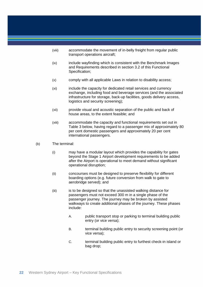
Figure 17. Use of clear and recognisable letterforms — Zurich Airport, Switzerland. .................... 42
Figure 18. Use of airline logos within standard signage — Adelaide Airport. ................................. 42
Figure 19. Use of clear, simple, modern text and imagery designed with an integrated approach —
Vienna International Airport, Austria. ...................................................................................... 42
Figure 20. Use of clear, simple, modern text and imagery designed with an integrated approach —
Vienna International Airport, Austria. ...................................................................................... 42
Figure 21. Use of clear, unified set of symbols and colour schemes — Frankfurt Airport .............. 43
Figure 22. Use of creative wayfinding — Narita International Airport, Japan. ................................ 44
Figure 23. Use of clear, unified set of symbols and colour schemes — Melbourne Airport. ........... 44
Figure 24. Basement carpark, Casselden Victoria. ........................................................................ 46
Figure 25. Bus Station in Osijek, Croatia. ...................................................................................... 47
Figure 26. Christchurch International Airport, New Zealand. ......................................................... 47
Figure 27. Mineta San José International Airport, USA. ................................................................ 47
Figure 28. Terminal entrance — Mineta San José International Airport. ........................................ 49

Western Sydney Airport – Key Functional Specifications v
Figure 29. Terminal entrance — Canberra Airport. ........................................................................ 49
Figure 30. Terminal entrance — Canberra Airport. ........................................................................ 49
Figure 31. Floor and ceiling of retail areas — Sydney Airport T1. .................................................. 51
Figure 32. Floor and ceiling of retail areas — Sydney Airport T1. .................................................. 51
Figure 33. Ceiling — Zhengzhou Xinzheng Airport, China. ........................................................... 51
Figure 34. Ceiling Departure gate areas — Beijing Airport, China. ................................................ 52
Figure 35. Floor and Ceiling — Canberra Airport. ......................................................................... 52
Figure 36. Identifiable transition point consistent with the whole airport design — Canberra Airport.
.............................................................................................................................................. 53
Figure 37. Passport security screening — Gatwick Airport. ........................................................... 53
Figure 38. Central security screening — Schiphol Airport. ............................................................ 54
Figure 39. Vision Box immigration system..................................................................................... 54
Figure 40. Creative and colourful material selection. Men’s room at Symantec, USA. ................... 55
Figure 41. Creative, colourful and engaging material selection and signage. Queen Victoria
shopping centre, Melbourne. .................................................................................................. 55
Figure 42. Clean and simple washroom. Royal Ontario Museum, Canada. ................................... 55
Figure 43. Sydney Airport T1. ....................................................................................................... 57
Figure 44. Brisbane Airport International Terminal departures lounge. .......................................... 57
Figure 45. Newcastle Airport. ........................................................................................................ 57
Figure 46. Stansted Airport, UK. ................................................................................................... 57
Figure 47. Use of neutral tones, separation by use of changed texture, e.g. hard to softer flooring
areas — Canberra Airport. ..................................................................................................... 58
Figure 48. Sufficient seating space and visibility of airfield — Adelaide Airport. ............................ 59
Figure 49. Spatial and volumetric difference — San Jose International Airport, USA. ................... 59
Figure 50. Use of neutral tones along with highlighted colour, e.g. soft, relaxing areas — Istanbul
Ataturk Airport, Turkey. .......................................................................................................... 60
Figure 51. Creative seating with contrasting texture and materials — Modular seating. ................ 60
Figure 52. Creative seating and colour highlighting feature destination point — Schiphol Airport. . 61
Figure 53. Aerobridges as an extension of the overall design — Canberra Airport. ....................... 62
Figure 54. Gates at LaGuardia Airport, New York, USA. ............................................................... 62
Figure 55. Miami Airport, Florida, USA. Art installation Harmonic Convergence by Christopher
Janney. .................................................................................................................................. 63


Western Sydney Airport – Key Functional Specifications 1
Minister’s Foreword
The Australian Government has committed to building the Western Sydney Airport and will ensure
it incorporates best practice in its design.
The Functional Specifications refer to design standards and principles for the airport, which form
part of the contractual terms on which the Government will require WSA Co to build the airport.
The Airport Plan and this key Functional Specification document govern the design of the airport.
We are committed to a high-quality airport – one that is appropriate for its initial traffic, but one that
also allows for capacity expansion over time.
Western Sydney Airport will be a full-service and modern airport catering for all types of domestic
and international services. The Stage 1 airport will have a 3.7 kilometre runway and facilities to
cater for up to 10 million passengers a year.
These Functional Specifications are the result of extensive consultation, including with airport
planning experts Landrum and Brown, who have designed terminals world-wide, including
Singapore’s award-winning Changi Airport.
Last year, I had the opportunity to inspect how design features are enhancing passenger
experience at Changi Airport, including the use of natural light and large windows that provide a
clear view of aircraft on the tarmac from the moment of entering the terminal, making travelling less
stressful for passengers. Closer to home, we can learn from the new terminals at Canberra and
Adelaide, which provide a benchmark for what can be achieved.
As a greenfield development, Western Sydney Airport has considerable potential – and an
advantage over other major Australian airports. Rather than renovating or retrofitting, it will be
purpose-built to ensure a streamlined and pleasant experience for inbound and outbound
travellers, incorporating new and emerging technology to provide seamless check-in and the
provision of swing gates – which can be used for both domestic and international flights – to
enhance operational efficiency.
The airport will incorporate sustainability in its design, including by adopting Infrastructure
Sustainability Council of Australia ratings, Green Star ratings and the National Australian Built
Environment Rating System. As an international gateway to Western Sydney, the airport will
express the character and culture of the region in its design.
Western Sydney Airport together with the Government’s plans enacted with the NSW Government
through the Western Sydney City Deal will transform the Western Sydney economy, providing
generations of growth and prosperity.
Through extensive planning we are delivering a landmark airport of which Western Sydney and
Australia can be proud.
Paul Fletcher
Minister for Urban Infrastructure

2 Western Sydney Airport – Key Functional Specifications
Overview
Background
In April 2014, the Australian Government announced that Badgerys Creek would be the site for a
new airport for Western Sydney. The Australian Government recognises that there are a number of
benefits a new airport will bring, and has set out the following objectives for the project to ensure
these benefits are achieved:
improving access to aviation services for Western Sydney;
resolving the long-term aviation capacity constraints in the Sydney basin catchment area;
maximising the value of the Western Sydney Airport as a national asset and its economic
benefit for Australia;
optimising the benefits of the Western Sydney Airport for employment and investment in
Western Sydney; and
delivering sound financial, environmental and social outcomes to the Australian
community.
To meet these objectives, Western Sydney Airport will be developed in accordance with a
comprehensive set of contractual requirements developed by the Australian Government. One of
these contractual requirements is to develop the airport in accordance with Key Functional
Specifications. The Key Functional Specifications set out physical development requirements,
forming the design standards and performance targets that the airport developer will need to
achieve.
Developing Functional Specifications
The Functional Specifications were developed following an extensive process to analyse the
forecast demand and required capacity for Western Sydney Airport. Accordingly, the Functional
Specifications should be read with reference to other key documents developed to support this
process — in particular, the Airport Plan, the Environmental Impact Statement and the Business
Case. The Functional Specifications take the essential airport requirements described in the Airport
Plan and put them into performance standards and targets that the airport developer must meet.
In developing the Functional Specifications, the Australian Government engaged internationally
recognised technical experts across a range of disciplines, including airport master planning,
design, engineering, property development, aviation operations and environmental science. The
Government has consulted with stakeholders, including airlines, utility service providers, road and
rail authorities, the border protection agencies, Airservices Australia and the Civil Aviation Safety
Authority. Extensive consultations have been undertaken with the NSW and surrounding Local
Governments to ensure the airport is integrated with the broader Western Sydney region.

Western Sydney Airport – Key Functional Specifications 3
Importantly, the Functional Specifications require that Western Sydney Airport is not only compliant
with Australian laws, particularly in areas such as safety and security, but that it meets international
standards and industry best practice to deliver a passenger-focused experience. Western Sydney
Airport will be designed to meet the International Air Transport Association’s Optimum Level of
Service. This international benchmark sets high-achieving performance targets across all aspects
of the passenger experience, with the aim of reducing waiting times in areas such as check-in,
security screening and immigration controls, as well as ensuring comfortable levels of space are
provided in public areas such as departure lounges and boarding gate.
An airport for the future
The Functional Specifications focus on the works needed to develop the first stage of Western
Sydney Airport. This will provide for an airport capable of meeting anticipated demand for at least
five years after operations commence — up to 10 million passengers per year. Western Sydney
Airport will be a full-service airport right from the beginning of operations. This means that it will
accommodate leisure and low-cost airlines, as well as all full-service domestic and international
airlines. The airport and runway will be capable of accommodating the full range of aircraft types,
including the Airbus A380. It will provide domestic and international flights, as well as infrastructure
for handling around 220,000 tonnes of freight a year.
Looking to the future, the Functional Specifications require the airport to be designed for continued
growth, with future expansion staged in a way that will have minimal disruption on existing
operations. This includes expansion of the terminal and commercial facilities, and the construction
of the second parallel runway, estimated to be required around 2050.
How the Key Functional Specifications will be used
The Functional Specifications describe the standards the Government expects Western Sydney
Airport to achieve, and allows the airport developer flexibility in innovative design to meet these
standards. This approach focuses on the performance outputs and targets, and leaves the detailed
physical design of the airport in the hands of the airport developer, WSA Co.
As part of this process, WSA Co will be required to finalise its high-level design for the airport,
referred to as the Airport Site Layout, before it embarks on major construction works. WSA Co is
expected to engage world-leading airport master planners and designers to prepare the Airport
Site Layout.
WSA Co will then be required to submit its finalised Airport Site Layout to the Department of
Infrastructure and Regional Development, the Australian Government department responsible for
overseeing the delivery of Western Sydney Airport. This will involve a thorough evaluation of WSA
Co’s layout plans by technical experts to ensure the proposed plans meet all aspects of the
Functional Specifications and Airport Plan and, therefore, achieves the Government’s expectations
and objectives.

4 Western Sydney Airport – Key Functional Specifications
As detailed design and construction of WSA commences, an independent Airport Building
Controller, with legislative powers under the Commonwealth Airports Act, will be required to
approve all airport building works. This will ensure that all airport works are consistent with the
developments approved by the Airport Plan and the Environmental Impact Statement, and meet
engineering and building standards, including the Building Code of Australia.

Western Sydney Airport – Key Functional Specifications 5
1. Introduction
(a) This Functional Specification sets out the requirements for the design and construction of the Airport. For the avoidance of doubt, the requirements set out in this Functional Specification are additional to and supplementary to any requirements set out in the Airport Plan (though the undertaking of the Airport works is subject to relevant authorisations being provided under the Airport Plan for such works).
(b) The Developer must design and construct the Airport so that, as at the start of operations, the Airport:
(i) is an airport capable of servicing full service and low cost carriers;
(ii) is capable of providing domestic and international regular public transport operations and freight air services for the Stage 1 Capacity specified in this Functional Specification; and
(iii) is capable of accommodating any aircraft types (including Airbus A380 aircraft) in regular operations and providing an alternate Code E and Code F airport to Sydney (Kingsford-Smith) Airport.
(c) The design of the Airport must:
(i) take into account the safety of workers and the public during construction and operation of the Airport by adopting best practice design principles;
(ii) be developed in a manner that reflects the Western Sydney Airport's location in one of Australia's largest economies and most populous cities;
(iii) be sustainable, efficient, flexible, responsive to context and a clear expression of the requirements of this Functional Specification;
(iv) have regard to security by design;
(v) have regard to environmental constraints and mitigate the impact of the development in accordance with the Airport Plan;
(vi) take into account requirements of Australian Government agencies that may operate at the Airport;
(vii) provide:

6 Western Sydney Airport – Key Functional Specifications
A. for the safe and efficient movement of people, aircraft and other vehicles and materials into, out of and within the Western Sydney Airport;
B. for the safe and efficient processing and transfer of passengers and their baggage to, from and between aircraft; and
C. airlines with an efficient operating environment and opportunities for product differentiation for their diverse needs;
(viii) provide for a high level of service, amenity, accessibility and security for all customers, visitors and service providers;
(ix) take the following into consideration:
A. the size of individual developments on the Airport Site must not dominate the landscape (except where such developments are critical to the Western Sydney Airport, such as the terminal and control towers);
B. design for cultural expression, human scale environments and inviting building frontages;
C. access to natural light;
D. operational, maintenance and environmental services efficiency;
E. integrated design approach with landscaping and public art;
F. environmentally sustainable design, climate and water sensitive principles in design and in selection of materials and colours; and
G. requirements for wildlife hazard management;
(x) take into account the staged future development and ongoing maintenance of an airport capable of handling approximately 82 million annual passengers in a manner which minimises the impact on operational efficiency or passenger convenience; and
(xi) ensure that the Airport is demonstrably and efficiently capable of future expansion with minimal disruption to existing operations, including:

Western Sydney Airport – Key Functional Specifications 7
A. to accommodate commercial facilities, ground access, upgrades to the terminal and additional aviation infrastructure;
B. to accommodate any rail development;
C. to provide for a second, parallel runway (the Future Second Runway) as further described in section 3.5(d); and
D. to accommodate in the future approximately 82 million passengers per year, at a service level that meets the standards or requirements to meet the International Air Transport Association (IATA) Optimum Level of Service.
(d) The Airport locality is as set out in Figure 1.
Figure 1. Airport locality

8 Western Sydney Airport – Key Functional Specifications
2. Definitions In this document, the following words have the following meanings:
“Airport” means the "Stage 1 Airport";
“Airport Plan” means the airport plan for the Airport Site as determined under section 96B of the
Airports Act in December 2016 as varied from time to time in accordance with the Airports Act;
“Airport Site” means the site which is the airport site for the “Sydney West Airport” (as specified in
the Airports Act), as varied from time to time;
“Airports Act” means the Airports Act 1996 (Cth);
“Airside” means "airside area" as defined in the Aviation Transport Security Act 2004 (Cth);
“ATM” means air traffic movements;
“Benchmark Developments” means Canberra and Adelaide airports;
“Busy Hour” means the busiest hour on the second busiest day of the average week of the peak
month. The Busy Hour may vary according to the relevant infrastructure element;
“CAT IIIB” means instrument landing system category IIIB, as defined by ICAO;
“Commercial Access Road” means the road connecting south-western areas of the Airport Site,
identified in the Airport Plan for business development and aviation logistics and support
(commercial, freight and maintenance activities), to the external link road connecting to the
realigned The Northern Road at the south-western boundary of the Airport Site;
“Design Life” means the minimum design lives specified in section 5 of this Functional
Specification for the given loadings;
“Future Second Runway” has the meaning given in section 3.5(d) of this Functional
Specification;
“IATA” means the International Air Transport Association;
“ICAO” means the International Civil Aviation Organization;
“ICAO Standards and Recommended Practices” means the international civil aviation
Standards and Recommended Practices (SARPs) published by ICAO;
“Landside” means "landside area" as defined in the Aviation Transport Security Act 2004 (Cth);
“Main Access Road” means the primary public access road, connecting the terminal facilities
(including public parking facilities, public transport connections, car rental, drop-off and pick-up) to
the external M12 Motorway spur road at the northern (Elizabeth Drive) boundary of the Airport Site;
“Modal share” means the anticipated split between private cars, taxis, public transport and other
modes of transport at the Airport;
“MOS” means the Manual of Standards published by the Civil Aviation Safety Authority;

Western Sydney Airport – Key Functional Specifications 9
“Narrow Body Equivalent Gates” or “NBEG” means the index described in section 3.8(e) of this
Functional Specification;
“Navigational Aids” means the infrastructure and systems described in section 3.12 of this
Functional Specification;
“Peak Hour” means the hour of a standard day where traffic flow is considered to be the highest,
determined from traffic modelling of passenger arrivals/departures based on the Busy Hour, airport
employee arrivals/departures, expected commercial activities (including business park activities,
airport deliveries and commercial support traffic) and taking into account a reasonable modal share
and traffic profiles on connecting roads;
“Public Road Network” means the roads accessible by the public immediately outside the Airport
Site;
“RET” means rapid exit taxiways;
“Stage 1 Airport” means the airport to be designed and constructed to the capacity set out in this
Functional Specification;
“Stage 1 Capacity” the capacity of the Airport, and the facilities within the Airport, specified in
section 3 of this Functional Specification;
“Stage 1 Runway” has the meaning given in section 3.5(c) of this Functional Specification;
“Support Facilities” means the facilities described sections 3.9 to 3.11 of this Functional
Specification;
“Swing” means terminal facilities common to both domestic and international operations, enables
the total estimated terminal space requirement to be less than would be required and increases
terminal flexibility, such as up-gauging of domestic aircraft, sharing of passenger processing,
increasing the efficiency of transfers and increasing the use of contact gates (equipped with
aerobridge).

10 Western Sydney Airport – Key Functional Specifications
3. Key Requirements Notwithstanding any other provision of this Functional Specification, the Airport (as applicable)
must satisfy the requirements set out in this section 3.
3.1 General
(a) The Airport must include the following:
(i) Airside facilities including runways and associated infrastructure — as further described in sections 3.5 to 3.7;
(ii) terminal facilities — as further described in section 3.8;
(iii) a ground transport network within the Airport Site as further described in section 3.8, including:
A. the Main Access Road within the Airport Site from the M12 Motorway spur;
B. the Commercial Access Road within the Airport Site from the realigned The Northern Road;
C. other required connections within the Airport Site with existing internal roads, internal site roads and with external roads at the Airport Site boundary;
D. Airside roads and an Airside perimeter road;
E. access for emergency services vehicles;
F. provision for cyclists and pedestrians; and
G. provision for passenger drop off and pick up, car parking, delivery vehicles, taxi, hire cars and bus staging,
that integrates with any rail development;
(iv) earthworks and drainage, water quality and flood management infrastructure;
(v) support facilities required to support the Airport's operations including freight handling and aircraft (and support ground vehicle) fuelling facilities — as further described in sections 3.9 to 3.11;
(vi) facilities for Australian Government agencies; and
(vii) utility works — as specified in section 3.13.

Western Sydney Airport – Key Functional Specifications 11
(b) The Airport must be capable of:
(i) operating as a CAT IIIB airport with the appropriate provisions that provide for a safe and efficient aerodrome ground operation;
(ii) providing domestic and international regular public transport operations and freight air services at the Stage 1 Capacity as detailed in Table 3; and
(iii) future expansion as described in sections 1(c)(x) and 1(c)(xi).
(c) The Airport must be designed and constructed:
(i) to achieve performance requirements set out in this Functional Specification; and
(ii) so as to comply with, without any operational or physical deviation or waiver from, all requirements in the Manual of Standards (MOS) 139, unless otherwise agreed.
(d) The Airport works include:
(i) all works and other requirements which would be required by Law to be completed or satisfied given the Airport is expected to be designated as a "major international airport" for the Air Navigation Act 1920 (Cth), including works required in accordance with any of the following or their associated legislative instruments:
A. Airports Act 1996 (Cth);
B. Aviation Transport Security Act 2004 (Cth);
C. Crimes (Aviation) Act 1991 (Cth);
D. Customs Act 1901 (Cth);
E. Biosecurity Act 2015 (Cth);
F. Civil Aviation Act 1988 (Cth); and
G. Air Navigation Act 1920 (Cth), and
(ii) all security features required for airports designated as “category 1” for the purposes of the Aviation Transport Security Act 2004 (Cth) and related regulations.

12 Western Sydney Airport – Key Functional Specifications
3.2 Benchmark Design Requirements
(a) The quality, materials, aesthetics, urban design or level of architecture of each element of the Airport must be at least to the same standard as:
(i) subject to section 3.2(b), if the element is the subject of a Benchmark Image and Requirement as set out in section 6, the standard in that requirement or design principle; and
(ii) if the element is not the subject of a Benchmark Image and Requirement as set out in section 6, the standard for that element in the Benchmark Developments.
(b) The images in section 6 are set out solely as examples of what would meet the required standard and are not the relevant standard itself.
3.3 Functional Requirements
The design of each element of the Airport must accommodate the functional requirements set out
in the table below, which correspond with the IATA Optimum Level of Service parameters.
Table 1: Functional Requirements
Area per passenger
(m2/passenger)
Waiting Time Standards for
Processing Facilities – Economy Class
(minutes)
Waiting Time Standards for
Processing Facilities – Business Class
(minutes)
Seating Availability
(% of passengers)
Public Departure Hall 2.3
Check-in: Self-Service Boarding Pass/Tagging
1.3 – 1.8 0 – 2 0 – 2
Check-in: Bag Drop Desk (queue width 1.4 – 1.6 m)
1.3 – 1.8 0 – 5 0 – 3
Check-in: Check-in Desk
1.3 – 1.8 10 – 20 3 – 5
(Business Class Check-in Desk)
0 – 3
(First Class Check-in Desk)
Security Checkpoint (queue width 1.2 m)
1.0 – 1.2 5 – 10 0 – 3 (Fast Track)
Emigration (Passport Control) (queue width 1.2 m)
1.0 – 1.2 5 – 10 0 – 3 (Fast Track)
Boarding Gate Lounge – Seating
1.5 – 1.7

Western Sydney Airport – Key Functional Specifications 13
Area per passenger
(m2/passenger)
Waiting Time Standards for
Processing Facilities – Economy Class
(minutes)
Waiting Time Standards for
Processing Facilities – Business Class
(minutes)
Seating Availability
(% of passengers)
Boarding Gate Lounge – Standing
1.0 – 1.2 50 – 70 (noting that the lower limit is only to be considered if extensive F&B
seating is provided in the departure lounge, or concession zone seating is
available)
Immigration (Passport Control) (queue width 1.2 m)
1.0 – 1.2 10 5 (Fast Track)
Immigration (Passport Control) (queue width 1.2 m) – Transfers
5 0 – 3 (Fast Track)
Baggage Claim Area – Narrow Body
1.5 – 1.7 0 – 15
(first passenger to first bag)
0 – 15
(first passenger to first bag)
Baggage Claim Area – Wide Body
1.5 – 1.7 0 – 25
(first passenger to first bag)
0 – 15
(first passenger to first bag)
Public Arrival Hall 1.2 – 1.7 15 – 20
CIP (Commercially Important People) Lounges
4.0
3.4 Airport Site Layout
The layout of the infrastructure and facilities on the Airport Site must be in accordance with:
(a) an airport site layout approved by the Australian Government; and
(b) the Land Use Plan contained in Part 2 of the Airport Plan.
3.5 Runway and Airfield
(a) The runway and airfield must be designed so that, on and from the commencement of operations, the Airport is capable of:
(i) subject to paragraph (b), maintaining an aerodrome reference Code 4F; and
(ii) without limiting paragraph (i), accommodating all aircraft types (including Codes B and C aircraft which include regional jets and turboprops) up to and including the largest wingspan aircraft of Code F or any other code which:

14 Western Sydney Airport – Key Functional Specifications
A. is in commercial operation as at the date when the airport site layout is approved (including Airbus A380); or
B. as at the date when the airport site layout is approved, the Developer knows, or ought reasonably to know, is planned to commence commercial operations in future (whether the aircraft has been, is currently being, or in future will be built).
(b) Code F aircraft will be the critical design aircraft for the Airport, except in cases where a lower code of aircraft is more critical. Deviation from Code F standards is permitted only in parts of the Airside precinct area in circumstances where it can be demonstrated that full Code F use is not required under normal operating conditions, having regard to the objective of maximising the aeronautical capacity of the Western Sydney Airport in the long term.
(c) The Airport must include a runway (the Stage 1 Runway) which must, as at the date when operations commence, unless otherwise agreed:
(i) comply with all MOS 139 requirements;
(ii) comply with the 05/23 runway coordinates and indicative elevation detailed in Table 2 below;
(iii) be 3,700 m in length; and
(iv) be 60 m in width.
The pavements for the Stage 1 Runway and taxiways must be designed and constructed so as to meet the estimated traffic loadings which are reasonably expected to be imposed during the Design Life of the pavements.
(d) The layout of the Airport Site must:
(i) allow for the future development of the Future Second Runway the same length as, and parallel to, the Stage 1 Runway;
(ii) allow for a 1,900 m runway separation between the Stage 1 Runway and the Future Second Runway; and
(iii) allow both ends of the Stage 1 Runway to conduct CAT IIIB instrument approaches.

Western Sydney Airport – Key Functional Specifications 15
Table 2: Stage 1 Runway alignment
RUNWAY END 05 23
EASTING 286914.0611 290067.1149
LATITUDE (SOUTH) S033o 53’ 30.28” S033o 52’ 29.75”
NORTHING 6247443.7898 6249379.8297
LONGITUDE (NORTH) E150o 41’ 44.65” E150o 43’ 48.97”
INDICATIVE ELEVATION (Metres above sea level) 93.09 metres 73.22 metres
Figure 2. Stage 1 Runway orientation (for information purposes only)
(e) The airfield must include:
(i) aircraft parking stands, taxiways, taxilanes and aprons as further specified in this section 3.5 and section 3.6, which enable the safe and efficient movement of aircraft between the Stage 1 Runway and the terminal;
(ii) navigational aids as further specified in section 3.12;
(iii) unless otherwise agreed, two sets of two rapid exit taxiways (RETs) at 30 degrees to the runway (in each direction of the runway), in addition to 90-degree intersection exits. The fillets on the RETs must be wide enough to enable arriving aircraft to make safe 150-degree turns onto the parallel taxiway en route to the terminal area. For information purposes only, an example of such RETs is shown in Figure 3; and

16 Western Sydney Airport – Key Functional Specifications
(iv) a combination of contact (aerobridge served) stands and non-contact (walk on/walk off) stands for the domestic and international operations.
Figure 3. Indicative RETs
(f) There must be a single full-length parallel taxiway and the taxiway system must be designed to provide:
(i) the safe and efficient movement of aircraft (whether under power or towed); and
(ii) sufficient queuing space for the departing aircraft and to provide bypass capability near the runway ends. This can be achieved by providing intersection departure points, in addition to the standard full-length departure points on both sides of the runway.
Where practicable, the Airport must be designed so as to limit the use of taxilanes to those areas where:
(iii) aircraft will manoeuvre to and from parking positions; and
(iv) aircraft taxi speeds would be reduced due to the proximity of other aircraft ramp stand areas.
(g) The layout for the Airport Site must allow for the future development of:
(i) two full-length field taxiways parallel to each runway; and
(ii) two sets of dual parallel cross-field taxiways linking and each providing two-way circulation capability between the northern and southern airfields, where the distance from the end of the runway to the intersection of the link taxiway is adequate to enable sufficient aircraft departure queuing on the taxiway and avoid blockage of the

Western Sydney Airport – Key Functional Specifications 17
taxiway system. Additional connector taxiways between the dual parallel cross-field taxiways must be allowed for to provide bypass capability.
(h) The Airport (including materials and building heights) design must not interfere with the successful operation of ground-based and aircraft radar and air traffic control which is expected to be provided through an air traffic control tower (ATCT) and which is to be located in accordance with the approved airport site layout.
3.6 Stage 1 Taxilane and Apron Requirements
(a) Unless otherwise agreed:
(i) the design of the aprons and taxilanes must allow for aircraft push-back operations being entirely on the aprons and taxilanes and not on the main parallel taxiway or cross-field taxiways;
(ii) aircraft push-back zones and taxilanes and taxiway separations from the ramp area must provide safe and efficient movement of arriving and departing aircraft and avoid excessive push-back distances;
(iii) the design must eliminate delays to the extent reasonably practicable and congestion during push-back operations;
(iv) for cul-de-sac configurations, the design of the airfield must allow for future development of dual taxilanes on all aprons that are expected to house five or more aircraft parking stand positions in the future;
(v) for linear terminal configurations, the design must provide for multiple taxiway access points so that manoeuvring aircraft can be bypassed and access to the main parallel taxiway is not unduly delayed;
(vi) all contact and active aircraft stands must be provided with an aircraft (reticulated) hydrant refuelling system to the stands; and
(vii) aircraft stands, ramp areas, aircraft engine start points, apron areas, taxiway and taxilanes must be designed to avoid aircraft jet-blast impacts (breakaway thrust) on any ramp area, including ground support equipment (GSE) movement/staging areas.
(b) Figures 4 and 5 provide examples of apron layouts which provide for stand width and depth that are all Code F capable (or Code E if more critical) in accordance with the following clearance zones:
(i) head of stand (HoS) roadway, tug manoeuvring and positioning zone (subject to the size of tug);

18 Western Sydney Airport – Key Functional Specifications
(ii) aircraft to tug position clearance (MOS 139 — 3.0 m); and
(iii) an aircraft tail of stand (ToS) roadway may be provided. Where a ToS road is provided, clearance from aircraft tail to ToS road (MOS 139 — 3.0 m) will be provided.
(c) The design for the stands must provide equal or better outcomes than the example apron layouts shown below at Figures 4 and 5 in relation to the following:
(i) aircraft servicing;
(ii) taxilane support;
(iii) push-back zones;
(iv) jet-blast considerations;
(v) hydrant fuelling;
(vi) safety zones;
(vii) aerobridge manoeuvring zones;
(viii) GSE staging and storage areas;
(ix) safe walk out or bussing stand provisions; and
(x) Airside road layout for efficient circulation of GSE and Airside vehicles.

Western Sydney Airport – Key Functional Specifications 19
Figure 4. Code C/E Aircraft Stand Layout Plan
Figure 5. Code F and Multiple Aircraft Ramp Systems Stand Layout Plan
20 Western Sydney Airport – Key Functional Specifications
3.7 Aircraft Isolation Area and Compass Calibration Pads
(a) The Airport must include:
(i) an aircraft isolation area which provides an isolated aircraft parking position for suspect aircraft; and
(ii) a compass calibration pad which provides for the calibration of an aircraft’s compass during maintenance procedures.
(b) The aircraft isolation pad and the compass calibration pad may be provided on separate pads or on a single pad.
(c) The aircraft isolation area must:
(i) be designed for parking an aircraft that needs isolation from normal aerodrome activities, including where an aircraft is believed to be the subject of unlawful interference;
(ii) be located not less than 100 m from other aircraft parking positions, buildings, or public areas; and
(iii) not be located over underground utilities, such as gas and aviation fuel, or other critical infrastructure and to the extent reasonably practicable must not be located over underground electrical or communication cables.
(d) The aircraft compass calibration pad must:
(i) include a compass rose to accommodate aircraft which are not adaptable to compass calibration set (commercial, regional jets, and propeller driven aircraft); and
(ii) be located in a position which has the minimum possible local magnetic disturbances and magnetic interference.
3.8 Terminal and Landside Facilities
(a) Unless otherwise agreed, the terminal must:
(i) be integrated with all ground transport, including any rail development;
(ii) include kiosk, bag drop, security, emigration/immigration (citizen, non-citizen and smart gates), quarantine inspection services, baggage handling facilities, baggage claim (including inbound baggage offload belts), security screening, departure lounges,

Western Sydney Airport – Key Functional Specifications 21
commercial tenant areas, back of house facilities and car rental facilities;
(iii) include baggage handling facilities which:
A. facilitate efficient and secure processing of all baggage in accordance with security requirements prescribed by Law; and
B. are robust and flexible for changing market conditions, and readily capable of expansion so as to cater for the forecast growth of the Western Sydney Airport beyond the Stage 1 Capacity;
(iv) be located between the Stage 1 Runway and the Future Second Runway, providing direct access to the Stage 1 Runway and, when expanded in the future, the capability to allow for easy and unobstructed access to the Future Second Runway via the taxiway system;
(v) be an integrated international and domestic terminal with at least two public passenger levels;
(vi) include:
A. a security screening area;
B. a customs arrivals area and customs departures area;
C. a quarantine facility; and
D. an immigration arrivals hall and immigration departures hall,
which must be designed:
E. to enable passengers to be processed using a combination of automated processes and staffed positions; and
F. to provide for international passengers’ checked and carry-on items to be subject to custom control and clearance and quarantine,
(as applicable);
(vii) be designed so as to accommodate airline lounges as required by airlines which will provide services to the Western Sydney Airport;
22 Western Sydney Airport – Key Functional Specifications
(viii) accommodate the movement of in-belly freight from regular public transport operations aircraft;
(ix) include wayfinding which is consistent with the Benchmark Images and Requirements described in section 3.2 of this Functional Specification;
(x) comply with all applicable Laws in relation to disability access;
(xi) include the capacity for dedicated retail services and currency exchange, including food and beverage services (and the associated infrastructure for storage, back-up facilities, goods delivery access, logistics and security screening);
(xii) provide visual and acoustic separation of the public and back of house areas, to the extent feasible; and
(xiii) accommodate the capacity and functional requirements set out in Table 3 below, having regard to a passenger mix of approximately 80 per cent domestic passengers and approximately 20 per cent international passengers.
(b) The terminal:
(i) may have a modular layout which provides the capability for gates beyond the Stage 1 Airport development requirements to be added after the Airport is operational to meet demand without significant operational disruption;
(ii) concourses must be designed to preserve flexibility for different boarding options (e.g. future conversion from walk to gate to aerobridge served); and
(iii) is to be designed so that the unassisted walking distance for passengers must not exceed 300 m in a single phase of the passenger journey. The journey may be broken by assisted walkways to create additional phases of the journey. These phases include:
A. public transport stop or parking to terminal building public entry (or vice versa);
B. terminal building public entry to security screening point (or vice versa);
C. terminal building public entry to furthest check-in island or bag drop;

Western Sydney Airport – Key Functional Specifications 23
D. security screening point to main retail and food and beverage area;
E. main retail and food and beverage area to furthest gate;
F. any one gate to any other gate (for transiting domestic passengers);
G. inbound immigration to baggage claim; and
H. baggage claim to terminal building public exit.
Table 3: Stage 1 Capacity
Design Requirement Stage 1 Capacity
Numbers of Annual Passengers 10,000,000
Annual Passenger ATM (air traffic movements) 56,000
Annual Freight ATM 7,000
Annual Freight Throughput (tonnes) 220,000
Number and Type of Freight Aircraft Stands 4 Code E stands
Design Busy hour Passengers
Departing (passengers per hour) 2,000
Arriving (passengers per hour) 2,000
Design Busy hour ATM
Passenger (movements per hour) 19
Freight (movements per hour) 6
Peak movements per hour 21

24 Western Sydney Airport – Key Functional Specifications
Design Requirement Stage 1 Capacity
Narrow Body Equivalent Gates (NBEG)
(where no Swing provided)
28.6 (subject to section 3.8(c))
NBEG
(where Swing provided) (the Stage 1 Capacity
specified in this row is an example based on a 10%
Swing)
25.8 (subject to section 3.8(c))
% of Gates with Aerobridge Stands
Domestic 50%
International 50%
Total Floor Area of terminal Minimum of 65,000 m2
(c) The Airport must include the number of gates to satisfy the narrow-body equivalent gates (NBEG) requirement in Table 3 unless otherwise agreed.
(d) With respect to aircraft stands, it is acceptable for Code F stands to be developed as multiple aircraft ramp systems (MARS) capable (so as to permit the relevant stand to handle either two Code C aircraft or one Code F aircraft) provided that the Airport is capable of satisfying the code capability and number of stands or NBEG capacity required under this Functional Specification.
(e) The NBEG index is used to standardise the definition of a “gate” and to provide a consistent means for evaluating apron use. The index also assists with determining the scale of terminal facilities for potential passenger throughput. The index converts the gate requirments of diverse aircraft sizes so they are equivalent to the apron capacity of a typical narrow body aircraft gate. The amount of physical space each aircraft requires is based on the maximum wingspan and depth of the aircraft in its respective aircraft group as shown in Table 4 below. The NBEG indices nominated in Table 4 apply for the purposes of this Functional Specification.

Western Sydney Airport – Key Functional Specifications 25
Table 4: NBEG Stand Equivalencies
Aircraft Classification Code and Wingspan NBEG Index
Code C — 36.0 m Wingspan 1.0
Code E — 65.0 m Wingspan 1.8
Code F — 80.0 m Wingspan 2.2
(f) For information purposes only, the following is an example of how 28.6 NBEG may be provided with 21 gates:
8 x Code E (1.8) + 1 x Code F (2.2) + 12 x Code C (1.0) = 28.6 NBEG gates.
With 10 per cent Swing provided, a minimum of 25.8 NBEG may be provided
with 19 gates as follows:
7 x Code E (1.8) + 1 x Code F (2.2) + 11 x Code C (1.0) = 25.8 NBEG gates.
(g) The Airport must:
(i) provide car parking facilities for passengers and visitors to the terminal that:
A. are designed and constructed with all-weather sealed surfaces;
B. have a minimum of 20 per cent of public parking bays that are covered; and
C. enable passengers and other persons to travel safely and efficiently between the car park facilities and the terminal;
(ii) include all-weather sealed surface and covered passenger drop-off facilities which provides sufficient capacity for the safe and efficient flow of private vehicles based on the Peak Hour drop-off modal share (assuming a three minute drop-off period for each vehicle);
(iii) include all-weather sealed surface and covered passenger pick-up facilities which provides sufficient capacity for the safe and efficient flow of private vehicles based on the Peak Hour pick-up modal share (assuming a three minute pick-up period for each vehicle);
(iv) provide passengers with all-weather sealed surface and covered access from the covered car-parking facilities and drop-off facilities to inside the terminal building;

26 Western Sydney Airport – Key Functional Specifications
(v) be designed for the efficient flow of road traffic for private vehicles to travel to and from the connection with the Main Access Road at the boundary of the Airport Site to the car parking and drop-off facilities, assuming a free flow connection with the M12 Motorway;
(vi) be designed so as to maximise the efficiency of passengers' movement from the land transport system, including any rail development, to aircraft; and
(vii) be designed so that the roads in the Airport Site which connect with any external roads facilitate the safe and efficient flow of traffic from the external roads to the Airport Site roads (and vice versa) and otherwise minimise delay at entrance and exit points to the Airport.
3.9 Support Facilities — Freight
The Airport must include freight-handling facilities that include the following:
(a) a secure freight precinct, which may include a cargo terminal complex;
(b) a freight apron located either in an aviation logistics and support zone (AD3 in Figure 16 of the Airport Plan) at the western end of the Airport Site (its anticipated longer term location) or within the terminal support and services zone (AD2 in Figure 16 of the Airport Plan); and
(c) access to the freight precinct separate from the general public access to the terminal forecourt.
3.10 Support Facilities — Aircraft and Support Vehicle Fuelling
(a) The Airport must include appropriate facilities for the handling of fuel and lubricants, including storage for aviation turbine fuel and fuel for ground vehicles (diesel and unleaded fuels, with provision for electric vehicles and/or gas driven vehicles), fuel transfer infrastructure and aircraft defueling facilities.
(b) More specifically, the support facilities to be provided as part of the Airport must include the following:
(i) a fuel farm, with fuel storage capacity which must:
A. be equivalent to at least three days' requirements, comprising one day's anticipated immediate use and two days' reserve supply;
B. be calculated based on the volumes reasonably expected to be required to meet Stage 1 Capacity; and

Western Sydney Airport – Key Functional Specifications 27
C. include provision to enable all cleaning and maintenance activities to be undertaken without a reduction of the three days' storage capacity referred to in paragraph A.
(ii) The fuel farm must:
A. be designed to allow for incremental expansion of the fuel farm to ensure three days' fuel requirements can always be available on the Airport Site;
B. be located near the northern boundary of the Airport Site;
C. connect via a reticulated underground fuel piping system to a network of hydrants to be located at aircraft stands and designated hydrants to load ground-based refuelling trucks;
D. be accessible via an access road which accommodates the movement of B-double vehicles, for maintenance and inspection and any ongoing delivery of fuel by road tanker. This road must connect to Anton Road at the Airport Site boundary;
E. have a location, configuration, design and construction that is compliant with Australian Standard AS1940 and standards referenced therein; and
F. be designed to allow for the unloading of fuel by B-double vehicles, and must include capacity for the simultaneous unloading of a minimum of two B-double vehicles, and space provision for future increase to a minimum of five B-double vehicles simultaneously unloading.
3.11 Support Facilities — Other
The Airport must provide:
(a) facilities to enable:
(i) flight catering sufficient to meet the on-site catering requirements and facilities for processing off-site catering deliveries for all airlines operating at the Airport at the Stage 1 Capacity;
(ii) airport maintenance; and
(iii) aircraft washing;
(b) an aircraft maintenance area including an apron for aircraft maintenance; and

28 Western Sydney Airport – Key Functional Specifications
(c) an aircraft engine run-up area (with associated noise mitigation measures).
3.12 Navigational Aids
(a) The Airport must be designed and constructed to:
(i) accommodate all necessary Navigational Aids required by the relevant authorities, including those listed at Table 5, unless otherwise agreed;
(ii) be consistent with optimising the performance of those Navigational Aids; and
(iii) assure continuous operation of the CAT IIIB equipment.
(b) All Navigational Aids must be located in accordance with Airservices Australia's siting guidelines.
(c) For the avoidance of doubt, the listing of Navigational Aids in Table 5:
(i) is not an exhaustive list of the infrastructure and systems that may be required by relevant Authorities; and
(ii) the list of infrastructure and systems generally reflects current technology and is subject to change in response to advancements in technology.
Table 5: Navigational Aids
Navaids Runway Lighting
Precision Approach Path Indicator
Instrument Landing System — CAT IIIB
Glide Path
Localiser
Far Field Monitor
Distance Measuring Equipment
Advanced-Surface Movement Guidance and
Control System
Ground Based Augmentation System
High Intensity Runway Lights
Airfield Lighting Equipment Room, housing all control
systems and Constant Current Regulators of the Airfield
Ground Lighting system
High Intensity Approach Lighting
Touchdown Zone Lights
Runway threshold lights
Runway wing bar lights
Runway end lights
Runway guard lights
Taxiway Lighting Weather Equipment
Rapid Exit Taxiway Indicator Lights
Stop bars
Taxiway edge lights
Taxiway centreline lights
Movement Area Guidance Signs
One Runway Visual Range touchdown at each end of the
Runway
One Runway Visual Range roll-out at each end of the
Runway
One Runway Visual Range mid-point
Illuminated wind direction indicator

Western Sydney Airport – Key Functional Specifications 29
3.13 Utilities
Unless otherwise agreed, the utilities provided to the terminal must be designed to accommodate:
(a) the passenger capacity specified in Table 3; and
(b) all other persons (including visitors and workforce) and operations reasonably expected to use the Airport at that passenger capacity.

30 Western Sydney Airport – Key Functional Specifications
4. Sustainability Requirements
4.1 Compliance with Sustainability Plan
The Airport must comply with the Sustainability Plan made under the Airport Plan.

Western Sydney Airport – Key Functional Specifications 31
5. Design Life The elements of the Airport works identified in Table 6 must be designed and constructed to
perform their intended function, without replacement, refurbishment or significant maintenance for
the Design Lives specified in Table 6.
Where an element of the Airport works comprises components, the Design Life of the relevant
components may be less than the Design Life of the relevant element, provided that the Developer
can reasonably demonstrate that such components are consistent with minimising whole-of-life
costs and can be replaced or refurbished without impacting the continued operation of the Western
Sydney Airport.
Table 6: Design Life
Item
Number
Element of Airport works Minimum Design Life
1 Cuttings, including batter treatments 100 years
2 Drainage elements that are accessible for refurbishment
and maintenance including water quality treatment elements 20 years
3 Earthworks, including basins 100 years
4 Embankments, including reinforced embankments 100 years
5 Fences 20 years
6 Inaccessible drainage elements 100 years
7 Noise barriers, noise attenuation devices 50 years
8 Retaining structures including soil nails, rock bolts, capping
beams, soil reinforcement, facings, drainage 100 years
9 Scour protection 50 years
10 Pavements (Runways, Taxiways & Aprons) 40 years
11 Wearing Course if non-rigid 12 years
12 Flexible Pavements — Local Road Works
Wearing Course if non rigid — Local Road Works
20 years
12 years
13 Rigid Pavements — Local Road Works 40 years
14 Terminal building and roof structure/s 50 years

32 Western Sydney Airport – Key Functional Specifications
Item
Number
Element of Airport works Minimum Design Life
15 Terminal building envelope 25 years
16 Terminal building plant and equipment 15 years
17 Terminal building fit-out 15 years
18 Signs support structures 40 years
19 Utilities 30 years
20 On-site fuelling facilities 50 years

Western Sydney Airport – Key Functional Specifications 33
6. Benchmark Images and Requirements
6.1 Benchmarking approach
(a) Adelaide Airport and Canberra Airport are identified as the relevant Australian benchmarks for the design for Western Sydney Airport (WSA), given they are contemporary Australian airports of a similar size to the WSA Stage 1 development, and should be considered the minimum acceptable standard and quality.
(b) Approaches to airport design, airport security and operational requirements, such as immigration and baggage management, have progressed since the design of both Adelaide and Canberra Airports. Therefore, not all aspects of these facilities are operationally satisfactory or suitable benchmarks for WSA.
(c) Examples cited show approaches from Australian and international airport terminal facilities, including examples that may inform design considerations for the proposed new terminal and airport precinct at WSA.
(d) The primary focus for benchmarking are the parts of the Airport complex most heavily frequented by the public, including the approach to and interior of the terminal, as the interface between the Airside and Landside components of the Airport. These places and spaces form the primary gateway experience for travellers entering and leaving Australia and NSW, therefore the qualitative and human experience element of the facilities is highly significant.
(e) The benchmark requires the production of environmentally sensitive contemporary buildings of a high design quality that enhance the experience of airport users, the corporate image of the tenants and the vision of the Airport as a premier commercial address.
(f) The benchmark provides precedents for planning and design criteria to assist in ensuring that a high standard of development is maintained throughout the Airport. This will be achieved by:
(i) encouraging the design of high-quality, functional buildings that will provide premium commercial and business environments to define the WSA terminal precinct as a viable gateway to NSW and Australia;
(ii) providing a sense of place and a concept unique to Western Sydney, the Blue Mountains and NSW; enhancing the “gateway” experience with an integrated mix of different building uses and activities;
(iii) creating a public face to WSA by defining strong built form and landscape elements providing an inviting, safe and distinctive environment for travellers;

34 Western Sydney Airport – Key Functional Specifications
(iv) creating a distinctive ambience and identity with points of interest and features that provide clarity of navigation (refer to figures 6 and 7 below); and
(v) orienting the built form to respond to the Airport operational requirements while applying sustainable environmental principles.
Example — to assist in the interpretation of the requirements above, the following examples of
airport entrance and terminal precincts would meet the requirements.
Figure 6. Landscaped airport entrance and terminal precinct — Canberra Airport.
Image by GMB Architects.
Figure 7. Landscaped airport entrance and terminal precinct — Adelaide Airport. Image by GHDWoodhead with TCL.

Western Sydney Airport – Key Functional Specifications 35
6.2 Airport Entrance and Terminal Precinct
(a) The overall design of the airport entrance and areas of the terminal precinct visible to the public must provide a high quality experience that:
(i) reflects national and regional cultural identity, creating enjoyable, interesting, and memorable experiences and environments; (refer to figures 8 and 10 below)
(ii) is integrated and appealing with a consistent approach;
(iii) has clear, uncomplicated circulation and a high-quality entry to the Airport, including developing external and internal airport visitor circulation for people, public transport and other traffic (refer to figures 8 and 9 below);
(iv) contributes to safe and efficient movement through the Airport of visitors, who may be unfamiliar with their surroundings;
(v) efficiently resolves pedestrian access and priority within the terminal car park;
(vi) configures entry/exits and car parking to respond to functionality;
(vii) provides / encourages high-quality streetscape;
(viii) is designed by registered architects; and
(ix) demonstrates innovative design.
Example — To assist in the interpretation of the requirements above, the following examples of
airport entrance and terminal precincts would meet the requirements. See also Facade and Form.

36 Western Sydney Airport – Key Functional Specifications
Figure 8. A high-quality, landscaped airport entrance and terminal precinct — Canberra Airport.
Image by GMB Architects.
Figure 9. Use of clear traffic management controls and reflecting cultural identity —
Mumbai Airport, India.
Image by Robert Polidori.
Figure 10. Communal spaces and public art — Canberra Airport.
Image by GMB Architects.

Western Sydney Airport – Key Functional Specifications 37
(b) Landscaping and public art should be developed and in support of the entrance precinct as it develops. Plant selection should be predominantly native flora, selected to minimise the attraction of birds to the precinct. The overall design of the landscaped areas, including potential use of green spaces in and around the terminal itself, must:
(i) provide stormwater run-off from roofs and hardstand areas;
(ii) have minimised lawn areas and be drought tolerant, with a controlled reticulation system, using grey water from within the development where possible; and
(iii) be incorporated into the overall design, with gardens, green space, or active or passive recreational spaces (refer to figures below).
(c) Forecourts and lobbies should be designed as communal spaces that respond
to both the public and private realm.
Example — To assist in the interpretation of the requirements above, the following examples of
airport entrance and terminal precincts would meet the requirements. See also Facade and Form.
Figure 11. A high-quality, landscaped airport entrance and terminal precinct — Adelaide Airport.
Image by GHDWoodhead with TCL.

38 Western Sydney Airport – Key Functional Specifications
Figure 12. A high-quality, landscaped airport entrance and terminal precinct — Adelaide Airport.
Image by GHDWoodhead with TCL.
Figure 13. A high-quality, landscaped public
space — Lonsdale street, Dandenong.
Image by BKK Architects with TCL.

Western Sydney Airport – Key Functional Specifications 39
6.3 Facade and Form
(a) WSA should be a recognisable gateway for Sydney and NSW. A high-quality
design resolution of the complexities of contemporary airport terminal precinct facilities with a multi-transit overlay is required and must:
(i) assist passengers throughout their journey from beginning to end;
(ii) be clear, integrated, appealing and comprehensive with a consistent approach; and
(iii) be applicable to all precinct tenants, users and businesses looking to establish a visual presence with the precinct.
(b) The use of texture and colour should reflect the regional character of the Blue
Mountains and Western Sydney. Materials should be:
(i) of a high quality and robust;
(ii) employed and detailed in ways that are innovative and distinctive;
(iii) appropriate for the climate and be reflective of the broader landscape; and
(iv) expressed elementally in strong and definite structural form, with distinctive texture or colour to provide clarity of architectural form (refer to figures below).
(c) The roof should be a defining element of the architectural expression, as the
airport terminal buildings will be viewed from the air by arriving and departing passengers (refer to figure 16 below).
Example — To assist in the interpretation of the requirements above, the following examples of
terminal facades and forms would meet the requirements. See also Airport Entrance and Terminal
Precinct.

40 Western Sydney Airport – Key Functional Specifications
Figure 14. Airport Plaza — Adelaide Airport.
Image by GHDWoodhead with TCL.
Figure 15. Terminal entrance — Canberra Airport.
Image by GMB Architects.
Figure 16. Terminal entrance — Hamad International Airport, Doha, Qatar.
Image by Doha International Airport.

Western Sydney Airport – Key Functional Specifications 41
6.4 Wayfinding
(a) The precinct in close proximity to and including the terminal is the public face of WSA. As such, the overall objective is to maximise and standardise the design aesthetics of the precinct while meeting the signage and visibility needs of all tenants and passengers. The design of signage and wayfinding must, in particular, have regard to the provisions of 2(a) and 3(a) as set out above.
(b) Wayfinding for Airside and Landside areas should facilitate efficient movement and enhance the passenger experience. Areas for consideration should include the following:
(i) external and internal retail;
(ii) wayfinding legibility, size and positions (refer to figures 18 and 19 below);
(iii) signage hierarchy (refer to figures 17 and 20 below);
(iv) airport operational signage; and
(v) occupational health and safety (OH&S).
(c) Most sites will require certain signage for the efficient and safe operation of their business. All such signage shall comply with the following:
(i) the only signs to be used in car parks and internal roadways are those for vehicle and pedestrian directions and those required for OH&S;
(ii) signage is to be built and maintained to a high standard; and
(iii) signage visibility from street frontage is to be minimised as far as practicable (refer to figures 18 and 19 below).
Example — To assist in the interpretation of the requirements above, the following examples of
signage and wayfinding would meet the requirements. See also Airport Entrance and Terminal
Precinct, Parking, Public amenity.
42 Western Sydney Airport – Key Functional Specifications
Figure 17. Use of clear and recognisable letterforms — Zurich Airport, Switzerland.
Image by NewlySwissed.
Figure 18. Use of airline logos within standard signage — Adelaide Airport.
Image by Adelaide eGuide.
Figure 19. Use of clear, simple, modern text and imagery designed with an integrated approach — Vienna International Airport, Austria.
Image by Integral Ruedi Baur Paris.
Figure 20. Use of clear, simple, modern text and imagery designed with an integrated approach — Vienna International Airport, Austria.
Image by Integral Ruedi Baur Paris.
(d) All material used in the construction of signage shall be durable, long lasting and clean, and be consistent with the texture, colour and form of all materials used within the airport precinct.
(e) Signage must assist passengers throughout their journey from beginning to end through clear and legible wayfinding (refer to figures 21 and 22 below).

Western Sydney Airport – Key Functional Specifications 43
(f) Symbols used will be compliant with internationally accepted requirements for designs, colours, content and shapes and, where required, illuminated to aid visibility (refer to figures below).
Example — To assist in the interpretation of the requirements above, the following examples of
signage and wayfinding would meet the requirements. See also Airport Entrance and Terminal
Precinct, Parking, Public amenity.
Figure 21. Concept design for clear, unified set of symbols and colour schemes — Frankfurt Airport, Germany.
Image by Susstudio.

44 Western Sydney Airport – Key Functional Specifications
Figure 22. Use of creative wayfinding — Narita International Airport, Japan.
Image by Kenta Hasegawa.
Figure 23. Use of clear, unified set of symbols and colour schemes — Melbourne Airport.
Image by Troy Mortier.
6.5 Parking and public transport
(a) The parking facilities provided should be integrated, safe and well lit, and
provide:
(i) clear drop-off/pick-up arrangements;
(ii) short and long-term parking;
(iii) priority close parking;
(iv) access to public transport and alternatives, such as ride sharing;
(v) integrated parking management solutions, such as parking guidance systems and online booking; and
(vi) co-location of car rental offerings close to the arrivals hall that allow for technology development, such as online booking, electronic key pick-up/drop-off kiosks, and car rental vehicle inspection systems.
(b) The design of car parking and vehicular manoeuvring areas should take into account ease of navigation for drivers unfamiliar with the airport and must address:
(i) the separation of car parking from truck manoeuvring and service areas;

Western Sydney Airport – Key Functional Specifications 45
(ii) safe pedestrian access, including covered walkways (refer to figures 25 and 26 below);
(iii) limited and practical crossover placement; and
(iv) compliant disability parking and access.
(c) Public ground transport facilities need to be user friendly with clear and intuitive graphics/wayfinding in accordance with the Wayfinding benchmark requirements (refer to figures 24 to 25 below).
Example — To assist in the interpretation of the requirements above, the following examples of
parking signage and wayfinding would meet the requirements. See also Airport entrance and
Terminal precinct and Wayfinding.

46 Western Sydney Airport – Key Functional Specifications
Figure 24. Basement carpark, Casselden Victoria.
Image by Mark Duffus.

Western Sydney Airport – Key Functional Specifications 47
Figure 25. Bus Station in Osijek, Croatia.
Image by Mario Romulic &
Drazen Stojcic.
Figure 26. Christchurch International Airport, New Zealand.
Image by Designers Institute of
New Zealand.
Figure 27. Mineta San José International Airport, USA.
Image by Ken Paul.

48 Western Sydney Airport – Key Functional Specifications
6.6 Entrance to the terminal
(a) The entrance to the terminal building must, in particular, have regard to the
provisions of 2(a) 3(a) and 4(a) and also meet the following key requirements:
(i) maintain people movement and activity at the entry and within the terminal, particularly at the entry floor level;
(ii) incorporate multiple at-grade access points;
(iii) design frontages to encourage pedestrian movement and interaction through a variety of uses at ground level with the provision of entry doors, shopfronts, operable doors and windows to cafes;
(iv) avoid blank walls;
(v) apply to all precinct tenants, users and businesses looking to establish a visual presence with the precinct;
(vi) use public art/sculpture as a visual and physical link in a double-height space (refer to figures 29 and 30 below);
(vii) ensure the entry foyer and concourse are voluminous, creating a sense of comfort and welcome for travellers (refer to figures 28 to 30);
(viii) use materials and architectural features to articulate the built form and to introduce fine-grain elements that may encourage some public interaction with the airport architecture both at distance and in close proximity (refer to figures 28 and 29 below);
(ix) consider creating terminal facilities that support activity and a sense of vibrancy; and
(x) ensure that podiums address human scale in height and through design elements (refer to figures 29 and 30 below).
Example — To assist in interpretation of the requirements above, the following examples of
terminal entrances would meet the requirements. See also Airport Entrance and Terminal Precinct
and Facade and Form.

Western Sydney Airport – Key Functional Specifications 49
Figure 28. Terminal entrance — Mineta San José International Airport.
Image by Ken Paul.
Figure 29. Terminal entrance — Canberra Airport. Image by GMB Architects.
Figure 30. Terminal entrance — Canberra Airport.
Image by GMB Architects
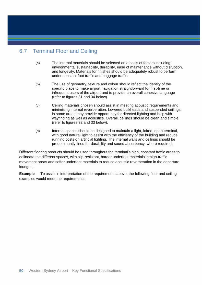
50 Western Sydney Airport – Key Functional Specifications
6.7 Terminal Floor and Ceiling
(a) The internal materials should be selected on a basis of factors including:
environmental sustainability, durability, ease of maintenance without disruption, and longevity. Materials for finishes should be adequately robust to perform under constant foot traffic and baggage traffic.
(b) The use of geometry, texture and colour should reflect the identity of the specific place to make airport navigation straightforward for first-time or infrequent users of the airport and to provide an overall cohesive language (refer to figures 31 and 34 below).
(c) Ceiling materials chosen should assist in meeting acoustic requirements and minimising internal reverberation. Lowered bulkheads and suspended ceilings in some areas may provide opportunity for directed lighting and help with wayfinding as well as acoustics. Overall, ceilings should be clean and simple (refer to figures 32 and 33 below).
(d) Internal spaces should be designed to maintain a light, lofted, open terminal, with good natural light to assist with the efficiency of the building and reduce running costs on artificial lighting. The internal walls and ceilings should be predominantly lined for durability and sound absorbency, where required.
Different flooring products should be used throughout the terminal’s high, constant traffic areas to
delineate the different spaces, with slip-resistant, harder underfoot materials in high-traffic
movement areas and softer underfoot materials to reduce acoustic reverberation in the departure
lounges.
Example — To assist in interpretation of the requirements above, the following floor and ceiling
examples would meet the requirements.

Western Sydney Airport – Key Functional Specifications 51
Figure 31. Floor and ceiling of retail areas — Sydney Airport T1.
Image by GHDWoodhead.
Figure 32. Floor and ceiling of retail areas
— Sydney Airport T1.
Image by GHDWoodhead.
Figure 33. Ceiling — Zhengzhou Xinzheng
Airport, China.
Image by CNADRI.

52 Western Sydney Airport – Key Functional Specifications
Figure 34. Ceiling Departure gate areas — Beijing Airport, China.
Image by Foster + Partners
Figure 35. Floor and Ceiling — Canberra
Airport.
Image by GMB Architects.

Western Sydney Airport – Key Functional Specifications 53
6.8 Security and Immigration checks
(a) Layout of security points should anticipate the airport’s future growth and have
sufficient flexible and adaptive space for:
(i) maintaining flow, screening and segmenting passengers without disruption;
(ii) providing a comfortable passenger experience to reduce potential stress (refer to figures 36 and 38 below); and
(iii) applying new technologies and automation (refer to figures 37 and 39 below).
(b) Navigation of passenger checkpoints should be both a seamless part of the
whole design and clearly identifiable as processing transition points (refer to image 36 and 38 below).
Example — To assist in the interpretation of the requirements above the following examples of
security and immigration checkpoints would meet the requirements. See also Wayfinding.
Figure 36. Identifiable transition point consistent with the whole airport design — Canberra Airport.
Image by GMB Architects.
Figure 37. Passport security screening — Gatwick Airport.
Image by Biometric Update.

54 Western Sydney Airport – Key Functional Specifications
Figure 38. Central security screening — Schiphol Airport.
Image by Schiphol Airport.
Figure 39. Vision Box immigration system.
Image by Vision Box.
6.9 Public amenity
(a) Access — The size and number of toilets and public amenities, including
parent rooms, shall reflect peak demand passenger numbers and be appropriately spaced and readily accessible throughout the terminal.
(b) Fixtures — All equipment and plumbing fixtures shall be tamper evident, anti-concealment and vandal resistant. Consideration should be given to innovation and technologies that provide functional and economic benefits, particularly with regard to water use and maintaining hygiene.
(c) Finishes — The selection of internal materials shall be based on the following factors: environmental sustainability, durability and ease of maintenance. Finishes must be easily cleaned and hard wearing, with the palette complementing the main circulation hall for a seamless transition. Floors must have a high slip rating and allow adequate space for signage and indicators (refer to figures below).
(d) Cleanliness and ease of circulation is critical to the operational requirements.
Example — To assist in the interpretation of the requirements above, the following examples of
public amenities would meet the requirements. See also Wayfinding and Terminal Floor and
Ceiling.

Western Sydney Airport – Key Functional Specifications 55
Figure 40. Creative and colourful material selection. Men’s room at Symantec in Mountain View, USA.
Image by Gensler.
Figure 41. Creative, colourful and engaging material selection and signage. Queen Victoria shopping centre, Melbourne.
Image by Dorma.
Figure 42. Clean and simple washroom. Royal
Ontario Museum, Canada.
Image by Tom Arban.

56 Western Sydney Airport – Key Functional Specifications
6.10 Retail Precincts
(a) Retail layout and design — Retail and refreshment areas should be visible,
accessible and themed, reinforcing the sense of place and travel experience through the use of advertising and public art, while creating a vibrant precinct (refer to figure 44 below).
(b) Passenger flow — The layout and design must not conflict with clear passenger wayfinding and movement, using effective signage in conjunction with clear sight-lines.
(c) Comfort — General seating areas should be close to and compatible with retail. Retail and refreshment areas should be integrated and placed where they will not be missed. Consideration should be given to food and beverage areas with views to the airfield (refer to figures 44 and 45).
(d) Materials — Shopfronts must be durable and of a design that allows individual retail expression. Tenancy fit-out guides must clearly outline acceptable finishes and materials to ensure a level of quality that will withstand the rigours of the retail environment, including use of hard and soft floor finishes. Softer or warmer finishes that absorb sound and light, such as carpet and timber, should be considered for more intimate dwell zones, such as food and beverage areas (refer to figures below).
Example — To assist in the interpretation of the requirements above, the following retail precinct
examples would meet the requirements. See also Terminal Floor and Ceiling.

Western Sydney Airport – Key Functional Specifications 57
Figure 43. Sydney Airport T1.
Image by GHDWoodhead.
Figure 44. Brisbane Airport International Terminal departures lounge.
Image by Arkhefield.
Figure 45. Newcastle Airport.
Image by SHAC.
Figure 46. Stansted Airport, UK.
Image by JHP Design.
6.11 Departure and Arrival Gates and Lounges
(a) Materials used should be high quality, durable and low maintenance, selected
with regard to:
(i) being harmonious to the region and identity;
(ii) the local climate;
(iii) the overall architectural ambition;
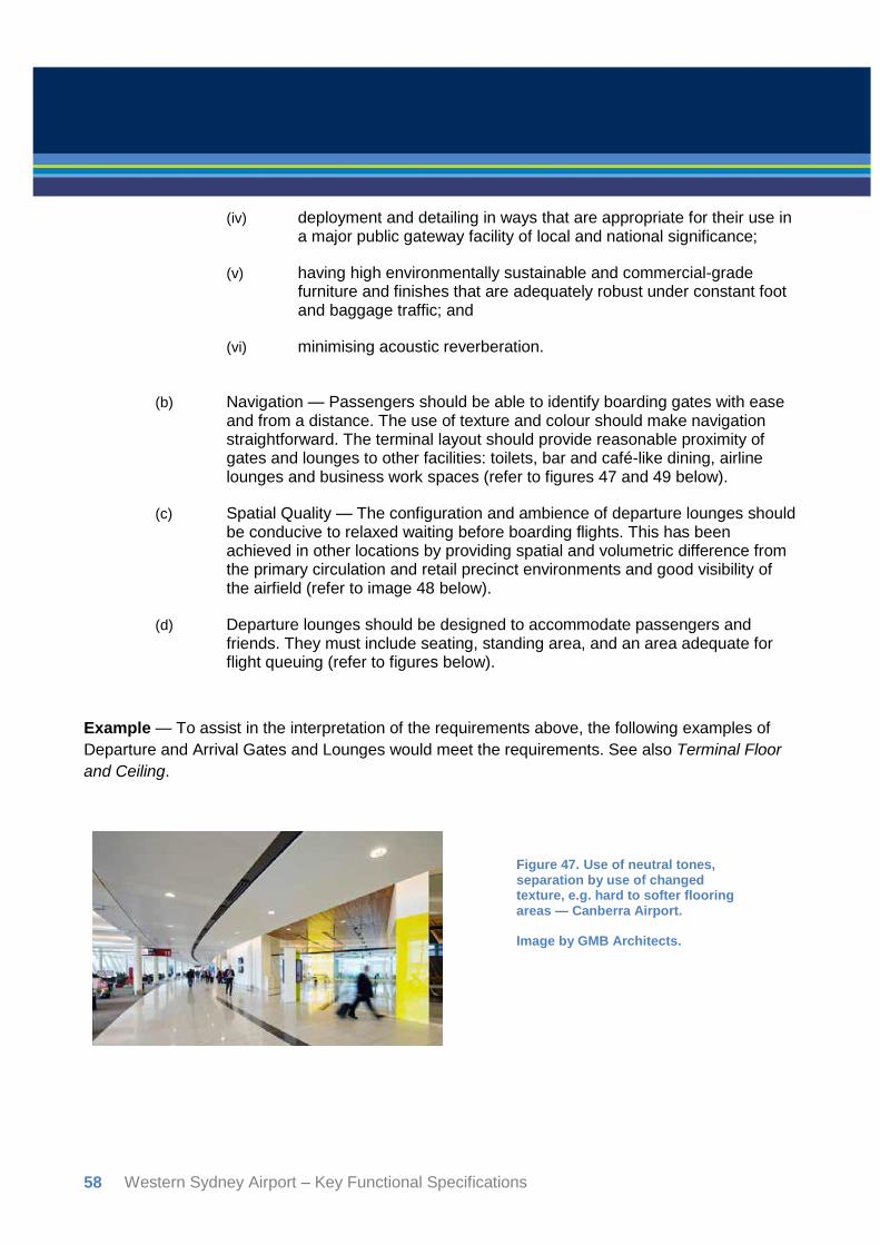
58 Western Sydney Airport – Key Functional Specifications
(iv) deployment and detailing in ways that are appropriate for their use in a major public gateway facility of local and national significance;
(v) having high environmentally sustainable and commercial-grade furniture and finishes that are adequately robust under constant foot and baggage traffic; and
(vi) minimising acoustic reverberation.
(b) Navigation — Passengers should be able to identify boarding gates with ease and from a distance. The use of texture and colour should make navigation straightforward. The terminal layout should provide reasonable proximity of gates and lounges to other facilities: toilets, bar and café-like dining, airline lounges and business work spaces (refer to figures 47 and 49 below).
(c) Spatial Quality — The configuration and ambience of departure lounges should be conducive to relaxed waiting before boarding flights. This has been achieved in other locations by providing spatial and volumetric difference from the primary circulation and retail precinct environments and good visibility of the airfield (refer to image 48 below).
(d) Departure lounges should be designed to accommodate passengers and friends. They must include seating, standing area, and an area adequate for flight queuing (refer to figures below).
Example — To assist in the interpretation of the requirements above, the following examples of
Departure and Arrival Gates and Lounges would meet the requirements. See also Terminal Floor
and Ceiling.
Figure 47. Use of neutral tones, separation by use of changed texture, e.g. hard to softer flooring areas — Canberra Airport.
Image by GMB Architects.

Western Sydney Airport – Key Functional Specifications 59
Figure 48. Sufficient seating space and visibility of airfield — Adelaide
Airport.
Image by Gnomad.
Figure 49. Spatial and volumetric difference — San Jose International Airport, USA.
Image by Nick Merrick.

60 Western Sydney Airport – Key Functional Specifications
(e) Comfort — Furniture and finishes should be geared towards a multi-use, activity-based environment, providing patrons with multiple options, such as single seating, communal seating and gathering spaces (refer to figures below).
(f) Materials used should be considered for sound absorbency. Floor finishes for waiting areas should be different from circulation spaces, with a softer flooring that is hardwearing and easily maintained.
(g) Selected lounge areas should include furniture with integrated connectivity services such as phone charging and data/internet connection.
Example — To assist in the interpretation of the requirements above, the following examples of
Departure and Arrival Gates and Lounges would meet the requirements. See also Terminal Floor
and Ceiling.
Figure 50. Use of neutral tones along with highlighted colour, e.g. soft, relaxing areas — Istanbul Ataturk Airport, Turkey.
Image by Turkish Airlines.
Figure 51. Creative seating and colour highlighting feature destination point — Schiphol Airport, Amsterdam, Netherlands.
Image by Schiphol Airport.

Western Sydney Airport – Key Functional Specifications 61
Figure 52. Creative seating with contrasting texture and materials — Modular seating.
Image by Alexander Lotersztain
6.12 Aerobridges
(a) Aerobridges should be considered in the overall design of the terminal so that
they become an extension of the terminal’s aesthetic, including safety and passenger comfort considerations. In contemporary airport terminal design aerobridge connections are glazed for passenger safety and visual comfort (refer to figures below).
(b) Where required, passenger path markings are to assist in the orderly movement of passengers embarking or disembarking during a walkout procedure.

62 Western Sydney Airport – Key Functional Specifications
Example — To assist in the interpretation of the requirements above, the following examples of
aerobridge as part of overall terminal design aesthetic would meet the requirements. See also
Facade and Form.
Figure 53. Aerobridges as an extension of the overall design — Canberra Airport.
Image by GMB Architects.
Figure 54. Gates at LaGuardia Airport, New York, USA.
Image by HOK.

Western Sydney Airport – Key Functional Specifications 63
Figure 55. Miami Airport, Florida, USA. Art installation Harmonic Convergence by Christopher
Janney.
Image by Designboom.

64 Western Sydney Airport – Key Functional Specifications
7. References Figure 1. Airport locality. Airport Plan 2016. Australian Government Department of Infrastructure &
Regional Development. http://westernsydneyairport.gov.au/files/Western_Sydney_Airport_Plan.pdf
Figure 2. Stage 1 Runway orientation. Airport Plan 2016. Australian Government Department of
Infrastructure & Regional Development.
http://westernsydneyairport.gov.au/files/Western_Sydney_Airport_Plan.pdf
Figure 3. Indicative RETs. Airport Plan 2016. Australian Government Department of Infrastructure
& Regional Development.
http://westernsydneyairport.gov.au/files/Western_Sydney_Airport_Plan.pdf
Figure 4. Code C/E Aircraft Stand Layout Plan. Australian Government Department of
Infrastructure & Regional Development.
Figure 5. Code F and Multiple Aircraft Ramp Systems Stand Layout Plan. Australian Government
Department of Infrastructure & Regional Development.
Figure 6. Canberra Airport Aerial view. Digital Image. Aviation business. n.p ,19-May-2016. Web
06 July 2016. http://www.aviationbusiness.com.au/news/canberra-to-host-airports-association-
conference
Figure 7. Adelaide Airport Car Park and Plaza. GHDWoodhead Pty Ltd
Figure 8. Canberra Airport Terminal Landscape Digital Image. Dz designs. DZ Designs, n.p. Web
06 2016. http://www.dzdesigns.com.au/ourwork/#/canberra-airport-terminal
Figure 9. Chhatrapati Shivaji International Airport. Digital Image. Inhabitat. Internet Brands Inc, 13
Feb 2014. Web 07 July 2016. http://inhabitat.com/soms-chhatrapati-shivaji-international-airport-is-
the-new-efficient-gateway-to-mumbai
Figure 10. Canberra International Airport/GMB Architects. Digital Image. Canberra Airport. Capital
Airport Group Website. n.d. Web 05 July 2016.
https://www.canberraairport.com.au/corporate/media-centre/gallery/
Figure 11. Adelaide Airport Car Park and Plaza. GHDWoodhead Pty Ltd
Figure 12. Adelaide Airport Car Park and Plaza. GHDWoodhead Pty Ltd
Figure 13. Lonsdale Street Dandenong/BKK Architects. Digital Image. Archdaily. Archdaily. 08 Aug
2013. Web 05 July 2016. http://www.archdaily.com/412359/lonsdale-street-dandenong-bkk-
architects
Figure 14. Airport Plaza — Adelaide Airport. GHDWoodhead Pty Ltd
Figure 15. Canberra International Airport/GMB Architects. Digital Image. Erincole Façade Systems.
Erincole Façade Systems. n.d. Web 05 July 2016. https://erincole.com.au/refurbishment-
projects/canberra-international-airport/

Western Sydney Airport – Key Functional Specifications 65
Figure 16. Doha International/HoK Architecture. Digital Image. Wallpaper*. Wallpaper (Time Inc
(UK) Ltd), 22 Dec 2015. Web 08 July 2016. http://www.wallpaper.com/gallery/architecture/building-
blocks-wallpaper-edit-of-most-striking-structures-from-around-the-world-2015
Figure 17. Zürich Airport. Digital Image. Newly Swissed. Newly Swissed GmbH. 05 Dec 2012 Web
06 July 2016. http://www.newlyswissed.com/impressions-from-zurich-airport-zrh/
Figure 18. Adelaide Airport landside drop off. Digital Image. Adelaide eGuide. Eguide Pty Ltd, n.d.
Web 06 July 2016. http://www.adelaideeguide.com/by-air.php
Figure 19. Vienna Airport/ Integral Ruedi Baur Paris. Digital Image. Integral Ruedi Baur Paris.
Integral Ruedi Baur Paris. n.d. Web 06 July 2016. http://www.irb-paris.eu/projet/index/id/84
Figure 20. Vienna Airport/ Integral Ruedi Baur Paris. Digital Image. Integral Ruedi Baur Paris.
Integral Ruedi Baur Paris. n.d. Web 06 July 2016. http://www.irb-paris.eu/projet/index/id/84
Figure 21. Frankfurt Airport Signage. Digital Image. Susstudio. Susstudio, n.d. Web 06 July 2016.
http://www.susstudio.com/Environment
Figure 22. Narita International Airport/NS+RK+P. Digital Image. Archdaily. Archdaily. 17 April 2015.
Web 06 July 2016. http://www.archdaily.com/620345/narita-international-airport-terminal-3-nikken-
sekkei-ryohin-keikaku-party
Figure 23. Melbourne Airport. Digital Image. Designworkplan. Designworkplan. n.d. Web 06 July
2016. http://designworkplan.com/design/airport-signage-photo-inspiration.htm
Figure 24. Basement carpark, Casselden Victoria. Best Wayfinding Design. (2014). 3rd ed. [ebook] Shenzen: Hi-Design International Publishing, pp.32-34. 05 July 2016.
https://issuu.com/hidesignpublish/docs/best_wayfinding_design_vol.3
Figure 25. Bus Station in Osijek/Rechner. Digital Image. ArchDaily. ArchDaily, 01 May 2012. Web
05 July 2016. http://www.archdaily.com/230675/bus-station-in-osijek-rechner
Figure 26. Christchurch Airport Signage/Designworks. Digital Image. Designers Institute of New
Zealand. Designers Institute of New Zealand, 2015 Web 05 July 2016.
https://bestawards.co.nz/graphic/environmental-graphics/christchurch-international-airport-
external-wayfin
Figure 27. Ken Paul, Norman Y. Mineta San Jose International Airport Terminal B. Digital Image.
ArchDaily. ArchDaily, 17 Aug 2011. Web 04 July 2016. http://www.archdaily.com/159529/norman-
y-mineta-san-jose-international-airport-terminal-b-fentress-architects
Figure 28. Ken Paul, Norman Y. Mineta San Jose International Airport Terminal B. Digital Image.
ArchDaily. ArchDaily, 17 Aug 2011. Web 04 July 2016. http://www.archdaily.com/159529/norman-
y-mineta-san-jose-international-airport-terminal-b-fentress-architects
Figure 29. Canberra International Airport/GMB Architects. Digital Image. Erincole Façade Systems.
Erincole Façade Systems. n.d. Web 05 July 2016. http://erincole.com.au/refurbishment-
projects/canberra-international-airport/

66 Western Sydney Airport – Key Functional Specifications
Figure 30. Canberra International Airport/GMB Architects. Digital Image. Canberra Airport. Capital
Airport Group Website. n.d. Web 05 July 2016.
https://www.canberraairport.com.au/corporate/media-centre/gallery/
Figure 31. Sydney International Airport. GHDWoodhead Pty Ltd
Figure 32. Sydney International Airport. GHDWoodhead Pty Ltd
Figure 33. Zhengzhou Xinzheng International Airport/CNADRI. Digital Image. ArchDaily. ArchDaily.
27 April 2016. Web 07 July 2016. http://www.archdaily.com/786356/zhengzhou-xinzheng-
international-airport-terminal-2-cnadri
Figure 34. Beijing Airport/Foster + Partners. Digital Image. Archdaily. Archdaily. 26 May 2008. Web
07 July 2016. http://www.archdaily.com/1339/beijing-airport-foster-partners
Figure 35. Canberra International Airport/GMB Architects. Digital Image. Canberra Airport. Capital
Airport Group Website. n.d. Web 05 July 2016. https://www.canberraairport.com.au/travellers/the-
new-terminal/sculptures/
Figure 36. Canberra International Airport/GMB Architects. Digital Image. Canberra Airport. Capital
Airport Group Website. n.d. Web 05 July 2016.
https://www.canberraairport.com.au/corporate/media-centre/gallery/
Figure 37. Gatwick Airport. Digital Image. Biometric Update. Biometrics Research Group Inc. 17
Sep 2012. Web 07 July 2016. http://www.biometricupdate.com/201209/gatwick-airport-wins-award-
for-use-of-biometrics
Figure 38. Schiphol Airport. Digital Image. Schiphol. Schiphol Nederland B.V. n.d. Web 06 July
2016.
http://www.schiphol.nl/Travellers/AtSchiphol/Privium/News/PriviumNews1/UpdateOnCentralSecurit
yAtSchiphol1.htm
Figure 39. Vision-Box Immigration System. Digital Image. Vision-Box. Vision-Box. 30 April 2015.
Web 06 July 2016. http://www.vision-box.com/news/improving-security-and-keeping-travellers-
happy/
Figure 40. Symantec Bathroom/Gensler. Digital Image. Gensler On. Gensler. 03 July 2016. Web
04 July 2016. http://www.gensleron.com/work/2016/3/7/why-corporate-bathrooms-stink-and-how-
good-design-can-fix-th.html
Figure 41. QV/Russell & George. Digital Image. Dorma. Dorma. 2012. Web 04 July 2016.
http://www.dorma.com/sg/en/inspiration-solutions/building-type/shopping-
retail/shopping_mall/queen_victoria_village_shopping_centre_melbourne_aus/project.html?idref=1
05
Figure 42. Royal Ontario Museum/Superkul. Digital Image. Interior Design. Sandow. 29 Jan 2015.
Web 04 July 2016. http://www.interiordesign.net/projects/10179-2014-boy-winner-kitchenbath/
Figure 43. Sydney International Airport. GHDWoodhead Pty Ltd
Figure 44. Brisbane International Airport/Arkhefield. Digital Image. Arkhefield. Arkhefield. n.d. Web
05 July 2016. http://www.arkhefield.com.au/projects/brisbane-international-retail-upgrade/

Western Sydney Airport – Key Functional Specifications 67
Figure 45. Newcastle Airport/SHAC. Digital Image. SHAC. SHAC. n.d. Web 05 July 2016.
http://www.shac.com.au/portfolio/newcastle-airport-retail-project-management
Figure 46. Stansted Airport WDFG/JHP Design. Digital Image. JHP Designers. JHP Design. 18
Nov 2014. Web 06 July 2016. https://jhpdesigners.wordpress.com/2014/11/18/jhps-work-for-world-
duty-free-at-london-stansted-airport/
Figure 47. Canberra International Airport/GMB Architects. Digital Image. Archello. Archello BV. 23
Aug 2016. Web 23 Aug 2016. http://www.archello.com/en/project/canberra-international-airport
Figure 48. Adelaide Airport/Hassell. Digital Image. Bonzle. Bonzle. n.d. Web 05 July 2016.
http://www.bonzle.com/c/a?a=pic&fn=zbudp9ts&s=4
Figure 49. Ken Paul, Norman Y. Mineta San Jose International Airport Terminal B. Digital Image.
ArchDaily. ArchDaily, 17 Aug 2011. Web 04 July 2016. http://www.archdaily.com/159529/norman-
y-mineta-san-jose-international-airport-terminal-b-fentress-architects
Figure 50. Istanbul Ataturk Airport Lounge. Digital Image. Turkish Airlines. Turkish Airlines. n.d.
Web 08 July 2016. http://www.turkishairlines.com/de-at/skylife/haberler/2012/dezember/ic-hatlar-
cip-salonu-yenilendi
Figure 51. Schiphol Airport. Digital Image. VolkerWessels Bouw Schiphol. Web 07 July 2016.
http://en.visserensmitbouw.nl/en/projects/detail/airport-park-schiphol
Figure 52. Prisma/Derlot. Digital Image. Derlot. Derlot. n.d. Web 08 July 2016.
http://derlot.com/furniture/prisma
Figure 53. Canberra International Airport/GMB Architects. Digital Image. Canberra Airport. Capital
Airport Group Website. n.d. Web 05 July 2016.
https://www.canberraairport.com.au/corporate/media-centre/gallery/
Figure 54. LaGuardia Airport Proposal. Digital Image. Dezeen. Dezeen Limited. 28 July 2015. Web
8 July 2016. http://www.dezeen.com/2015/07/28/new-york-laguardia-airport-demolished-rebuilt-
queens-usa-shop-architects-dattner-present-architecture/
Figure 55. Harmonic Convergence/Christopher Janney. Digital Image. Designboom. Designboom.
10 Nov 2011. Web 08 July 2016. http://www.designboom.com/art/miami-airport-installation-
harmonic-convergence-by-christopher-janney/