Western Soil, Ir- - PR.gov · Field work consisted in drilling three (3) ... Retained samples were...
46
Western Soil, Ir- Geotechnical-Environmental-Geological-Matevial "iesting Laboratory GEOTECHNICAL ENGINEERING REPORT ON SUBSURFACE EXPLORATION FOR MAYAGUEZ ELITE COMMERCIAL CENTER MAYAGUEZ, PUERTO RICO Box 345 Mayaguez PR 00681 258 McKinley St. MayagUez PR 00680 Phone 832-7612/Fax B32-76365'
Transcript of Western Soil, Ir- - PR.gov · Field work consisted in drilling three (3) ... Retained samples were...

Western Soil, Ir- Geotechnical-Environmental-Geological-Matevial "iesting Laboratory
GEOTECHNICAL ENGINEERING REPORT ON
SUBSURFACE EXPLORATION FOR
MAYAGUEZ ELITE COMMERCIAL CENTER MAYAGUEZ, PUERTO RICO
Box 345 Mayaguez PR 00681 258 McKinley St. MayagUez PR 00680 Phone 832-7612/Fax B32-76365'

PO BOX 345, MAYAGUEZ, PR 00681-0345 - TEL. (787) 832-7612 FAX (787) 832-6360
o".258 MCKINLEY STREET WEST, MAYAGUEZ, PR 00680
Western Soil, Inc. Geoteebnical-Environmental-Geological-Material Testing Laboratory
PRELIMINARY GEOTECHNICAL ENGINEERING REPORT
ON SUBSURFACE EXPLORATION
FOR MAYAGUEZ ELITE COMMERCIAL CENTER
MAYAGUEZ, PUERTO RICO
AUGUST 29, 2001
I�TRODUCTIO�
A commercial center is being proposed for a site in the Sabanetas Ward of Mayagtiez,
Puerto Rico. On behalf of Investment GP & SR, Inc., Dr. Ovidio Garcia requested a subsurface
ct exploration from this firm to determine preliminary subsoil conditions within the site, and present
preliminary geotechnical recommendations for the future project.
Subsurface exploration and laboratory tests were performed by Western Soil, Inc., under
the supervision ofan authorized representative, and engineeering analyses were conducted by Western
Soil, Inc. and the undersigned. This geotechnical engineering report presents exploration findings,
data interpretation, and the cited recommendations.
SITE LOCATION AND PROJECT - q_SCRIPTION
The site is on the southwest corner of the intersection between State Roads PR-2 and
PR-64, in the Sabanetas Ward of Mayagtiez, Puerto Rico. A partial view of the USGS topographic

Western Soil, Inc. GEOTECHNICAL-ENVIRONMENTAL-GEOLOGICAL-MATERIAL TESTING LAI1ORATORY
MAYACUEZ ELITE COMMERCIAL CENTER MAYAGUEZ, PUERTO RICO
2
map of the Mayaguez Quadrangle, illustrating the approximate location of the site, is shown in
Figure 1 (all figures mentioned in this report are included in Appendix 1).
According to an aerial photograph provided by the designers and a site reconnaissance,
the existing ground surface is flat. The site is crisscrossed by drainage channels and covered
by low vegetation.
The project is still under planning and site plans are not available yet, although it was informed
by the developer that a 5-foot high permanent fill is being planned. Previous experience in the
area indicates that the site lies on alluvial and potentially-compressible soils. Therefore, the site
will most likely need preloading in order to induce in advance settlements expected from primary
consolidation of the compressible strata.
SCOPE OF WORK
Field work consisted in drilling three (3) borings. Borings were staked with tape measure
approximately as shown in Figure 2. Additionally, three (3) consolidation tests were performed
on undisturbed samples obtained with Shelby tubes from B-3. Office work consisted of reviewing
technical literature, interpreting exploration findings, performing geotechnical engineering analyses,
and preparing this geotechnical engineering report.
All borings were performed by rotary drilling with hollow-stem augers in general accordance
with ASTM D 1452. Samples were recovered continuously for the upper 6 feet and in 5-foot
intervals thereon while performing the Standard Penetration Test (SPT) described in ASTM D
1586. Retained samples were transported in glass jars to the laboratory for visual-manual description

Western Soil, Inc. GEOTECIINICAL-ENVIRONNI DUAL-GEOLOGICAL-MATERIAL TESTING LABORATORY
MAYAGUEZ ELITE COMMERCIAL CENTER MAYAGUEZ, PUERTO RICO
3
and identification (ASTM D 2488), water content determination (ASTM D 2216), and unconfined
compression tests on cohesive samples by means of the spring tester or the hand penetrometer.
Measurements of depth to the probable phreatic level were made within the borings during
drilling. These observations, where applicable, are included in the boring logs. A description
of field and laboratory testing procedures used for this work is included in Appendix 2. Boring
logs are included in Appendix 3 and consolidation test results in Appendix 4.
GENERAL SUBSO' ' • CONDITIONS
Using the USGS Geologic Map of the Mayaguez and Rosario Quadrangles, Puerto Rico
(Curet, 1986) and previous experience in the subject area, the site lies on alluvium (Qal). The
cited geologic source describes alluvium as "poorly to moderately sorted and moderately to well-
bedded sand, silt and cobble or boulder gravel."
Based on the borings, limited by the maximum sampled depths, subsurface materials
consist of brown and grayish brown, medium to stiff silty clays and clayey silts interbedded by dark
gray, soft, organic clays. The potentially-compressible soils were found at a depth range
approximately between 10 and 60 feet. These soils have natural moisture contents ranging in
percentage from the high 50's in the upper half of the strata to over 100 toward the lower
boundary.
The groundwater level was found during drilling in all three (3) borings at an approximate
depth of 4 to 5 feet. As a result, the potentially-compressible soils are saturated. In any case,
accurate groundwater levels can only be measured by monitoring one or more observation wells
for several days, especially in clayey soils, until the water table is fairly stabilized. Furthermore,
phreatic levels vary with seasonal and climatic changes throughout the year.

Western Soil, Inc. GEOTECIINECAL-ENVIRONMENTAL-GEOLOGICAL-MATERIAL, TESTING LABORATORY
MAYAGUEZ ELITE COMMERCIAL CENTER
IVIAYAGDEZ, PUERTO RICO
4
DISCUSSION
Undisturbed samples were obtained at 20, 30 and 45 feet of depth to perform consolidation
tests and obtain the stress history of the soft sediments. Tests results show that the deposits
are overconsolidated for the stresses expected from the 5-foot high permanent fill, thus producing
settlement from recompression. However, any increase in load above that induced by the permanent
fill would be beyond the preconsolidation pressure; i.e., by compression, approximately
between 25 and 45 feet.
Based on compressibility parameters obtained from the consolidation tests and a 5-foot fill
height, settlement from primary consolidation of the compressible soils was estimated to be inthe
order of3 inches. Using the average coefficient ofconsolidation determined fromthe consolidation tests
for the range of final pressures expected to act within the compressible strata and further
assuming that drainage will occur only in the upward direction, the time-settlement relationship was
estimated for the 5-foot permanent fill. It was found that the time period required for the total
settlement induced by the weight of the permanent fill to be diminished would be too long (for
instance, 18 years for 2 inches to occur). Therefore, the only way to accelerate the 3-inch settlement
to be produced by the permanent fill is by preloading the site with a surcharge.
Following the same methodology used for the permanent fill, 5-foot and 10-foot high surcharges
were analyzed. Total settlements induced by these surcharges, in addition to the permanent fill,
were estimated in the order of 10.5 and 16 inches, respectively. Time-settlement relationships
were computed for each surcharge and all three curves were plotted as Figure 3. It is clear
from the curves that the 5-foot and 10-foot surcharges would induce the 3-inch settlement in time
periods of 3.2 and 1.4 years, respectively. As a result, a surcharge should be implemented for

Western Soil, Inc GEOTEGHNICAL-ENVIRONMENTAL-GEOLOGICAL-MATERIAL TESTING LABORATORY
MAVACCIEZ ELITE COMMERCIAL CENTER
MAYAGUEZ, PUERTO RICO 5
accelerating the expected total settlement in advance to construction. Should the construction of
the site be expedited, settlements may be induced even quicker by installing wick drains prior
to the placement of the surcharge. In any case, final grading plans (including existing topography)
should be furnished to this firm and an additional geotechnical investigation should be performed
in order to furnish foundation and earthwork recommendations in a final geotechnical engineering
report.
According to an aerial photograph provided by the designers and a site reconnaissance,
the existing ground surface is flat but crisscrossed by drainage channels and covered by low vegetation.
Thus thorough clearing and grubbing should be performed under the presence of a full-time soil
technician supervised by a registered geotechnical engineer, including removing entirely surficial sediments
and organic materials which may be encountered within and along existing drainage channels and
ditches. Although an additional geotechnical investigation is required before presenting final
recommendations, preliminary foundation and earthwork recommendations are presented inthe forthcoming
section of this report.
All depths mentioned in this report, unless otherwise specified, are referred to the existing
ground surface when drilling was performed. Detailed de scriptions o fthe soils and materials encountered
in the borings are shown in the boring logs. These logs show only the subsoil conditions found
on the dates and locations indicated in this report.
PRELIMINARY RECOMMENDATIONS
1. All earthwork activities should be observed and reviewed by a full-time resident soil technician
supervised by a geotechnical engineer or firm. These observations should include, but not be
limited to, clearing and grubbing, identification and removal oftopsoil and unsuitable materials

Western Inc. GEOTECHNICAL-ENVIRONMENTAL-GEOLOGICAL-MATERIAL TESTING LABORATORY
MAYAGUEZ ELITE COMMERCIAL CENTER MAYAGUEZ, PUERTO Rico
6
whichmay appear during construction, surcharge placement and monitoring, laboratory testing
and review of any proposed fill and backfill materials, in situ testing of compacted materials
for quality control, foundation inspections, and evaluation ofany unexpected subsoil or groundwater
condition found during construct ion. It is important to understand that the geotechnical engineer
or firm contracted to inspect the earthwork activities will adopt these recommendations in full,
endorsing or disagreeing with this report.
2. Clearing and grubbing ofthe existing grade is recommended. This activity includes removing
and stripping vegetation, topsoil, and extraneous materials (e. g., construction debris, timber,
underground and abandoned structures, etc.). A thickness of approximately 12 inches
may be used as an estimate for stripping; nevertheless, actual stripping should be determined
in the field during the first phase ofthe earthwork operations. Additionally, the soft sediments
and organic materials within and along existing drainage channels and ditches should be
entirely removed and backfilled with engineered fill. However, the actual vertical and horizontal
extent of removal should be determined in the field under the presence of a full-time soil
technician supervised by a registered geotechnical engineer, preferably from this firm.
3. Removed, replaced or stripped materials are objectionable as fill or backfill for foundation
purposes, unless these do not contain organic matter. Objectionable soils for foundation
may be used in passive or landscaped areas where structures or pavements will not be
constructed. Once the site has been cleared as previously recommended, the exposed
ground surface should be proof-rolled with a 20-ton vibratory roller at least 10 times in
both orthogonal directions. Any soft or loose soils detected during this operation should
be entirely removed and replaced with engineered fill.

Western Soil, Inc GEOTECHNICAL-ENVIRONMENTAL-GEOLOGICAL-MATERIAL TESTING LABORATORY
MAYAGIDEZ ELITE COMMERCIAL CENTER MAYAGUEZ, PUERTO RICO
7
4. Any fill and/or backfill should be placed in the dry. Otherwise, clean gravel should be
used until the surface within the bottom ofthe ditches and/or drainage channels overcomes
the groundwater level. The rest ofthe backfill may proceed as recommended inthe forthcoming
paragraphs. Prior to the placement ofpermanent fill, a 6-inch bedding of clean sand should
be placed throughout the entire area ofthe site to be filled. Then at least eight (8) settlement
plates and sixteen (16) piezometers (1 settlement plate and two piezometers at each location)
should be installed to monitor settlements and porewater pressures, respectively. Each
plate may consist of a 12" x 12" steel plate base with a 314-inch steel or PVC pipe riser
connected to the center of the plate. On the other hand, open standpipe piezometers
with porous polyethilene filter and self-sealing threaded PVC standpipes may be used. The
tips of the piezometers at each instrumented location may be placed within the upper and
lower thirds of the compressible strata.
5. Reference elevations ofthe settlement plates should be taken immediately after installation,
and prior to fill placement. Water elevations should be taken inside each piezometer as
well, Once fill placement begins, all instruments should be read twice weekly for at least
four weeks and then once a week until settlements expected from the permanent 5-foot
high fill are achieved. Based on the settlement-time and porewater pressure dissipation
data, the inspecting geo technical engineer should recommend removal ofsurcharge and beginning
ofconstruction. It should be noted that the 3-inch total settlement reported in this preliminary
investigation is an empirical estimate that will, be refined with further analyses once the final
geotechnical investigation is accomplished and the final grading plans are made available
to this firm.

Western Soil, Inc. GEOTECHNICAL-ENVIRONMENTAL-GEOLOGICAL-MATERIAL TESTING LABORATORY
MAYAGUEZ ELITE COMMERCIAL CENTER MAYAGUEZ, PUERTO RICO
8
6. Fill and backfill materials to be used as permanent fill, for existing soil replacement, under
future structures and under the structural slab, and for foundation backfills should classify
as GW, GP, GM, GC, SW, SP, SM, SC or CL in accordance with the Unified Soil
Classification System. However, materials classified as SC and CL may likely require rigurous
moisture control before placement and compaction. Materials classified as CH, ML, MH,
OL, OH and Pt should not be used as either fill or backfill. Furthermore, fill and backfill
materials should not contain muck, trees, stumps, brush, roots, construction debris, or soil
grains larger than 3 inches, and should not have critical volume expansion indeces. Materials
excavated from areas within the project may be used as long as these comply with the
soil classifications recommended above. However, any soil may be used for the surcharge.
7. Fill or backfill materials should be placed in maximum loose lifts o f8 to 10 inches in thickness,
depending on the type of fill and compaction equipment to be used, and compacted. The
selected compaction equipment should be capable of compacting the fill such that the rec-
ommended relative compaction is obtained without affecting adjacent structures. Backfill
around footings or confined areas, where a large roller does not work efficiently, should
be placed in maximum loose lifts of 4 inches. The latter should be carefully compacted
withhand-operated, mechanical raminers to prevent unnecessary distress to structural members
already constructed.
8. Field compaction for permanent fills and backfills should comply with 95% ofthe maximum
dry density obtained in the modified Proctor test (ASTM D 1557), or 100% ofthe maximum
dry density obtained in the standard Proctor test (ASTM D 698). Moisture content during

12. Final grading plans (including existing topography) should be furnished to this firm in
order to
plan the additional geotechnical investigation required, which should be performed to furnish
foundation and earthwork recommendations in a final geotechnical engineering report.
compaction should be maintained within -2 and +3% of optimum. However, surcharge

Western Soil, Inc. GEOTECHNICAL^ENVIRONMENTAL-GEOLOGICAL-MATERIAL TESTING LABORATORY
MAYAGUEZ ELITE COMMERCIAL CENTER MAYAGUEZ, PUERTO RICO
9
materials may be compacted with the same bulldozers used for spreading, without the need of
rollers.
9. Field density tests should be performed on each layer of compacted permanent fill by the
inspecting geotechnicalfirm or engineer. Additional rolling should be performed ifthe density
test results indicate that the relative compaction is less than that recommended. Scarification
and air-drying of the compacted surface may be required before rolling again ifthe moisture
content of the fill is too high. These tests are not required for the surcharge construction.
10. Conventional equipment may be used for excavating any ofthe soils found within the proposed
construction areas. In any case, all excavations should be performed in accordance with
29 CFR Part 1926, Occupational Safety and Health Standards-Excavations; Final Rule,
published bythe US FederalDepartment ofLabor, OccupationalSafetyandHealthAdministration.
11. Beam on elastic foundations (monolithic structural slabs) may be preliminarily planned for
proposed structures, provided that the site is prepared in advance as recommended. Foundations
may be designed preliminarily for an allowable subgrade reaction o f100 kc f, with a minimum
depth offoundationequivalent to its maximum engro ssed thickness.. However, final foundation
recommendations should be obtained from additional geotechnical investigations within the
proposed structures, once the entire site has been prepared appropriately.

12. Final grading plans (including existing topography) should be furnished to this firm in
order to
plan the additional geotechnical investigation required, which should be performed to furnish
foundation and earthwork recommendations in a final geotechnical engineering report.
Western Soil, Inc. GEOTECHNICAL-ENVIRONMENTAL-GEOLOGICAL-MATERIAL TESTING LABORATORY
MAYAGOEZ ELITE COMMERCIAL CENTER MAYAGIJEZ, PUERTO RICO
10
LIMITATIO�S OF THIS REPORT
This report is based on all design concepts, parameters and constraints which have been
made known to this firm. The final design may require revision of these recommendations, to
confirm their applicability to the new design.
The conclusions and recommendations presented in this report are the result of the best
evaluation made by this firm of the stratigraphic properties of soils and rock, as obtained from
the three (3) borings drilled for this report, and the corresponding laboratory tests performed in
accordance with geotechnical engineering standards. Interpretations andjudgments based on these
data may differ from actual conditions, since variations in the nature and behavior of subsurface
materials may occur within short distances. Therefore, it is important that the inspecting geotechnical
firm review footing excavations before footings are cast, in order to make sure that foundation
soils are suitable for supporting the footings. Moreover, final grading and foundation plans should
be provided to this firm for review, prior to construction bidding, and revision in case recommendations
need to be changed.
This document has been prepared specifically for the client and the project addressed herein.
Furthermore, it should
not be used for a
different project at this
sites without the
written consent of
Western Soil, Inc.
LA4CILI ENTE ERNA
PRESIDENT, WESTERN SOIL, INC.

Western Soil, Inc. Geotechnical-Environmental-Geological-Material Testing Laboratory
APPENDIX 1
FIGURES

Figure �o.1 Site Location Map
MayagOez Elite Commercial Center,
Sabanetas Ward, MayagiiezPuerto Ri©o
Scale 1:20,000

jily Inc
Geotechnical-Environinental-Geological-Material Testing Laboratory 258 McKinley St., Mayagliez Puerto Rico 00680 P.O.Box 346 MayagUez Puer 00081
Figure No.2 Boring Location Plan 'oyagE:iez Elite Commercial Building
Sabanetas Ward, hayagUez, Puerto Rico

FIGURE 3
MAYAGUEZ ELITE COMMERCIAL BUILDING SABANETAS WARD, MAYAGUEZ, PUERTO RICO
COMPUTED TIME - SETTLEMENT RELATIONSHIP
80 90 100
0.848 3
3.0
138

A ITENDIX 2
FIELL AND LABORATORY TESTING PROCEDURES
Western Soil, Inc. Geotechnical-Environmental-Geologieal-Material Testing Laboratory
Western Inc. Geotechnical-Environmental-Geological-Material Testing Laboratory
APPENDIX 2
FIELD AND LABORATORY TESTING PROCEDURES
DRILLI�G
Auger Borings. These are performed by turning a hollow-stem auger into the ground a short
distance. As the auger advances into the ground, the cuttings rise to the surface on the auger
spirals, although the depth from which the material comes cannot be accurately determined.
By using hollow-stem augers, samples can be recovered from the bottom of the auger, thus
eliminating the need for driving casings.
Wash. fir orings. Wash borings are performed by advancing 5-foot casings (3-inch in diameter)
into the ground with the drop of a 300-lb hammer from a height of 30 inches. The number
of blows for every foot of casing penetration is reported in the boring logs. When driving of
the casing becomes too difficult, due to the hardness of the soils encountered, and the hole does
not cave-in, the boring is advanced without casing by continuously washing out the soils with the
drill rods. The color and nature of the soils washed out is observed, examined and recorded
to have a general idea of the extent of the soil strata.
Core Borings. Usually performed on rock formations, a core borings are advanced by rotating
drill rods, a core barrel and a diamond bit. As the bit cuts into the rock, the rock core is
free to move into the inner core barrel head, which is suspended on a swivel. Therefore, the
rock core does not follow the rotary motion of the outer core barrel with its bit. Cooling
water or a bentonite slurry is circulated through the drill rods and the core barrel. Penetration

depends on the length of the core ban-el and the quality (amount ofjoints or fractures) of the
PO BOX 345, MAYAGUEZ, PR 00681-0345 - TEL. (787) .832-7612 FAX (787) 832-7612 258 MCKI6LEY STREET WEST, MAYAGUEZ, PR 00680

Western Soil, Inc Geotechnical-Environmental-Geological-Material Testing Laboratory
rock. Core runs are longer as rock quality increases. As the core barrel is withdrawn, the core
lifter, located inside the diamond bit, wedges itself around the bottom of the rock core, thus
permitting it to be pulled free from the underlying rock.
SAMPLI�G
Standard Penetration Test (ASTM D 1586). Standard Penetration Tests (SPT) are
performed by driving a 1.375-in ID X 2-in OD X 18- or 24-in long, split spoon sampler with
the drop of a 140-lb hammer from a 30-in height. The number of blows for every 6-in of
samplerpenetration is recorded, and thenumber ofblows between 6 and 18 inches ofpenetration
is reported as the N-value. Samples are stored and sealed in glass j ars for visual classification
and other routine laboratory tests. The SPT has been correlated with the consistency of fine-
grained soils, and the angle ofinternal friction or the relative density ofsands. Such correlations
can be used for preliminary engineering analyses and classification ofsoil strata ofa particular
site. For the case of sands, this firm has adopted the recommendations by De Mello, 1971:
obtain the angle of internal friction from N-values and overburden pressure to determine the
relative density. In the case offine-grained soils, the correlation ofthe SPT with the undrained
shear strength ofmedium and stiffsi Its and clays oflow sensitivity have been found to be fairly
good. However, in the case ofsoft silts and clays, the SPT yields poor estimates ofthe undrained
shear strength. Therefore, testing undisturbed samples, andperforming other in situ tests (e.g.,
vane shear, cone penetration, dilatorneter, etc.) may be more reliable for these cases.
Undisturbed Sampling. Undisturbed samples are obtained with thin-wall Shelby tube samplers, 2- to 5-in
OD by 30-in long. The sampler is forced into the soil by static force or downward pressure and is pulled
out also statically. These samplers are sealed in the field with wax and shipped to the laboratory.
Samples are then extruded at the time oftesting by pushing in the

Western Soil, Inc Geotechnical-Environmental-Geological-Material Testing Laboratory
same direction that the sample penetrated the sampler. Special care is taken in handling these
samples to minimize disturbance.
LABORAT 0 II .;,STIING
�atural Moisture Content (ASTM D 2216). This is the water content of the in situ soil.
It is obtained from either disturbed or undisturbed samples. Basically, about 40 grams ofsoil
is placed in an oven for 24 hours at a temperature of 1100 C. The difference in weight between
thenatural and oven-dried states ofthe soil, dividedbythedryweight ofthe dry sample, expressed
in percentage, is reported as the natural moisture content (wn).
Atterberg Limits (ASTM D 4318): These limits and related indices are commonly used
in geotechnical engineering for soil identification and classification purposes. However, these
are also empirically correlated to various parameters which are used for preliminary analyses.
Theprocedures used to determine liquid andplastic limits are described in the referenced ASTM
standard.
Unconfined Compression (ASTM D 2166). The best-quality samples recovered during
SPT performance are subjected to failure in unconfined compression. These samples are
disturbed and the shear strength obtainedis usually lower than the "true" in situ strength, depending
on the degree of disturbance and the soil sensitivity. Furthermore, increased brittleness of the
soil structure results in strength values lower than the in situ undrained strength. Therefore,
theunconfined strength value determined from asplit spoon sample is onlyused as index property
for classification and identification purposes. If more accurate strength values are required,
undisturbed samples are used.

Western Soil, Inc Geotechnical-Environmental-Geological-Material Testing Laboratory
SOIL DESCRIPTIO� (ASTM D 2488)
The description ofsoils include the color, type (gravel, sand, silt, clay, organic), consistency
(ifsoil is fine-grained), size and roundness (ifsoil is coarse-grained), and some other special
characteristics which can assist in the identification and classification of the soil. The latter
are those recommended for field classification (dilatancy, dry strength, shine and toughness).
To approximate the consistency of fine-grained soils (soft, medium, stiff, hard), a simple test
is performed with the hand; a hard fine-gained soil is difficult to indent with the thumb nail,
stiff soils are difficult to indent with the thumb, medium soils can be penetrated by moderate
thumb pressure, and soft soils are easily penetrated with the thumb. The description of coarse-
grained soils (sands and gravels) include size (fine, medium, coarse), and roundness (angular,
sub-angular, sub-rounded, rounded, and well-rounded, according to Peftijohn, 1949). The
relative amount ofcoarse fractions in fine-grained soils is estimatedby placing a representative
sample of some 50 grams in a graduated cylinder filled with water. The mix is shaken and
allowed to settle. Particles of a size larger than fine sand are visible to the naked eye, while
silts and clay are not. In this manner, estimates of the relative amount of the coarse fractions
are made and reported as:
Trace 1 - 10%
Some 10 - 20%
Sandy or Gravelly 20 - 35%
And 35 - 50%
The relative density of sands has been also correlated with the SPT as follows:
N-values Relative Density
0 -4 very loose
4 - 10 loose

Western Soil, Inc Geotechnical-Environmental-Geological-Material Testing Laboratory
Weathering
10 - 30 median
30 - 50 dense
> 50 very dense
These correlations are very approximate, and vary with, among other factors, overburden pressure
(Gibbs and Holtz, 1957, and Bazaraa, 1967). Moreover, these are meaningless in soils with a
significant amount ofgravel or cobbles. The relative amounts ofthe fine-grained soils is estimated
according to the reaction of the soil to dilatancy, shine, dry strength and toughness, with the adjective
indicating the less active fraction; i.e., a silty clay behaves more like a clay than a silt. The consistency
ofcohesive soils has also been correlated to the results ofthe SPT, as shown below. This correlation,
however, is greatly affected by the clay structure and factors such as sensitivity.
UnconfinediCompressive
Strength (tsf)
< 0.25
0.25 - 0.50
0.50 - 1.00
1.00 - 2.00
2.00 - 4.00
> 4.00
N-value
<2
2 - 4
4 - 8
8 - 1 5
15 - 30
> 30
Consistency
very soft
soft
medium
stiff
very stiff
hard
ROCK DESCRIPTIO�
Geologic features used to describe rock cores are weathering, hardness, joint bedding and
foliation spacing, percent recovery, RQD, etc. These arc explained in the following tables:

W e s t e r n 1 1 , I n c
Geotechoical-Environmental-Geological-Material Testing Laboratory
Sample Condition
Fresh, bright crystals, few joints may show slight staining. Rock rings under hatmner fcrystall in e.
Generally fresh, joint-stained, some joints may show clay if open, crystals in broken face show clay if open, crystals in broken face show bright. Rock rings under hammer ifcrystalline.
Generally fresh, joint-stained and discoloration extends into rock up to l ". Open joints contain clay. In granodiorite rocks, some feldspar crystals are dull and discolored. Crystalline rocks ring under hammer.
Significant portions ofrock show discoloration and weathering effects. In granodiorite rocks, most feldspars are dull and discolored; some show clayey. Rock has dull sound under hammer, and show significant loss of strength as compared with fresh rock.
All rocks, except quartz, discolored or severely stained. In granodiorite rocks, all feldspars are dull and most show kaolinization. Rock shows severe loss of strength and can be excavated with geologist pick. Rock goes "chunk" when struck.
All rocks, except quartz , discolored or stained. Rock "fabric" clear and evident, but reduced in strengh to strong soil. In granodiorite rocks, all feldspars are kaolinized to some extent.
Very Severe All rocks, except quartz,
Degree
Fresh
Very Slight
Slight
Moderate
Moderately Severe
Severe

Western Soil, Inca Ge����technical-Envitronmental-Geological-Material Testing Laboratory
discolored or stained. Rock "fabric" discerniblebut mass effectively reduced to "soil," with only fragments of strong rock remaining.
Complete Rock reduced to "soil." Rock
"fabric" not discernible, or discernible only in small scattered locations. Qu..- may be present as dikes or str xs.
Sample Conditions
Cannot be scratched with knife or sharp pick. Breaking of hand specimens requires several hard blows with geologist pick.
Can be scratched with knife or pick only with difficulty. Hard blow of hammer required to detach hand specimen.
Can be scratched with knife or pick. 1/4"-deep gouges or grooves can be excavated by hard blow with point of geologist pick. Hand specimens can be detached by moderate blow.
Can be grooved or gouged 1/16" deep by firm pressure of knife or pick point. Can be excavated in small 1" chips with geologist pick.
Can be gouged or grooved readily with knife or pick point. Can be excavated in chips, several inches in size, by moderate blows of a pick point. Small thin pieces can be broken by finger pressure.
Hardness
Degree
Very Hard
Hard
Moderately Hard
Medium
Soft
Western Soil, Inc.
Geoteehnicai-Environatental-Geologicol-Material Testing Laboratory
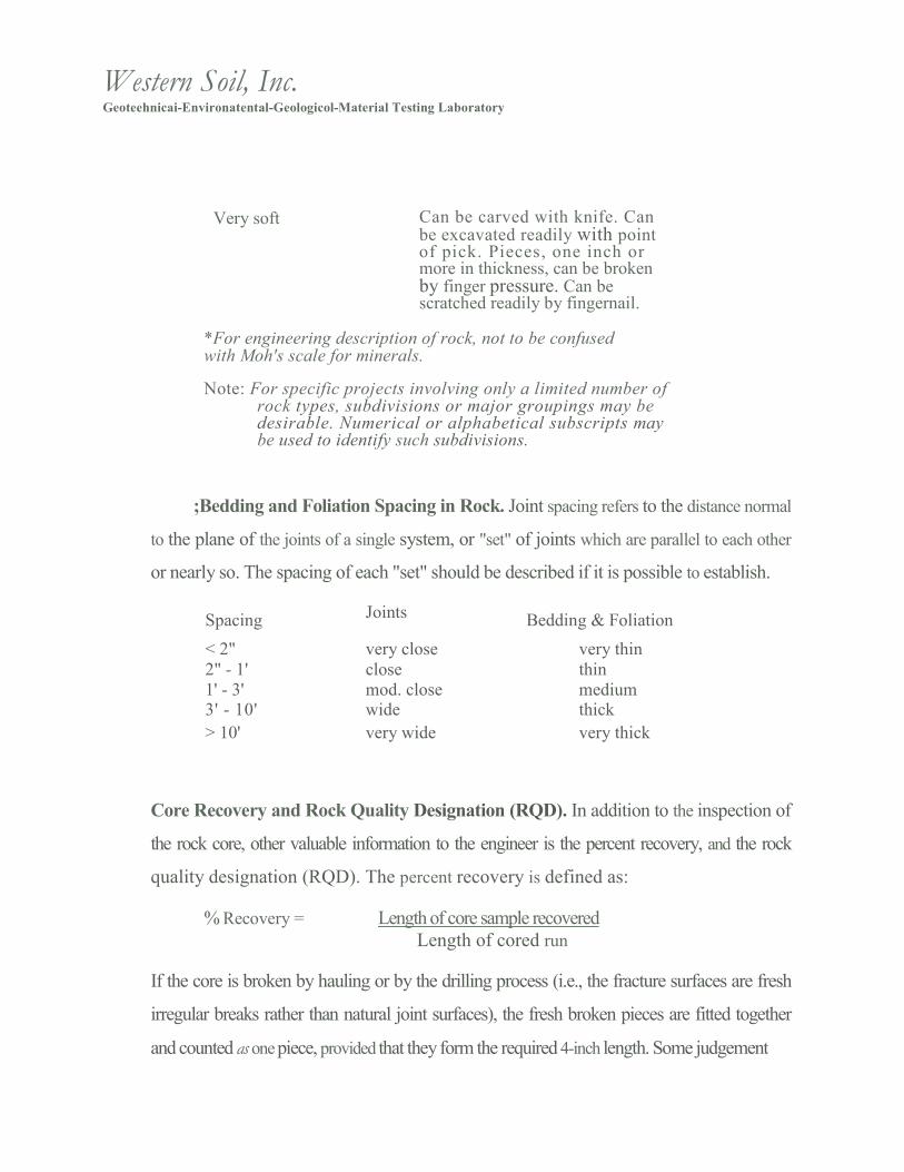
Very soft Can be carved with knife. Can
be excavated readily with point of pick. Pieces, one inch or more in thickness, can be broken by finger pressure. Can be scratched readily by fingernail.
*For engineering description of rock, not to be confused with Moh's scale for minerals.
Note: For specific projects involving only a limited number of rock types, subdivisions or major groupings may be desirable. 6umerical or alphabetical subscripts may be used to identify such subdivisions.
;Bedding and Foliation Spacing in Rock. Joint spacing refers to the distance normal
to the plane of the joints of a single system, or "set" of joints which are parallel to each other
or nearly so. The spacing of each "set" should be described if it is possible to establish.
Spacing Joints Bedding & Foliation
< 2" very close very thin
2" - 1' close thin
1' - 3' mod. close medium 3' - 10' wide thick
> 10' very wide very thick
Core Recovery and Rock Quality Designation (RQD). In addition to the inspection of
the rock core, other valuable information to the engineer is the percent recovery, and the rock
quality designation (RQD). The percent recovery is defined as:
% Recovery = Length of core sample recovered
Length of cored run
If the core is broken by hauling or by the drilling process (i.e., the fracture surfaces are fresh
irregular breaks rather than natural joint surfaces), the fresh broken pieces are fitted together
and counted as one piece, provided that they form the required 4-inch length. Some judgement

Western Soil,:.,sic.
Geoteelmieni-Environmental-Geological-Material Testing Laboratory
is necessary. The RQD is expressed in percent for NX or NWM cores as:
RQD Sum of the lengths of core pieces longer than 4 in
Length ofrun drilled
The quality of the rock is described as follows:
R Q D , %
0 - 2 5
2 5 - 5 0
5 0 - 7 5
7 5 - 9 0
90 - 100
Description ofRock Quality very poor
poor
Fair
good
excellent

Western Soil, Inc.
GeotechnicalkEnvironmental-Geological-iViateriml Toning Laboratory
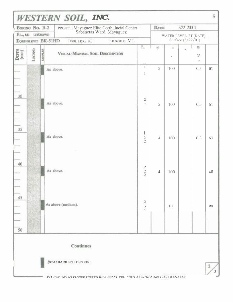
LIENDIX 3
BORING LOGS

Western Soil, Inca Ge����technical-Envitronmental-Geological-Material Testing Laboratory
f w 4
0.4
TE61 in, INC.
i m: unknown 1 EQUIPMENT:
BORING No. B-1 PROJECT: Mayaguez Elite Commercial Center
DATE:
5/16Sabanetas Ward, MayagUez
BK-511-ID DRILLER: JC LOGGER: ML
WATER LEVEL,
Surface
VISUAL-MANUAL SOIL DESCRIPTION
0 j crs
3 Brown, soft clayey silt, tiny roots. 3 83 2
As above. 2 4 78
2 3
above. 4 9 67 5
_s above. 4 4 10 56
6
5 xownish gray, stiff clayey silt. 5 10 100
5
5
As above. 5 13 100 8
Gray, soft clayey silt, rock fragments.
1
1
2 100
FT (DATE): (5/16/01)
rr
10
15
20
Continues
ISTANDARD SPLIT SPOON
PO Box 345 MAYAGOEZ PUERTO Rico 00681 TEL. (787) 832-7612 FAX (787) 832-6360

WESTER6 SOIL, I6'. DATE: 5/16/2001 PROJECT: Mayagfiez Elite Commercial Center
Sabanetas Ward, Mayaguez BORING No. B - 1
T L , r a n u n k n o w n WATER LEVEL, FT (DATE):
S u r f a c e ( 5 / 1 6 / 0 1 )
ray, soft clayey silt, rock fragments.
above.
\s above.
As above.
0
35
As above (medium).
Continues
STANDARD SPLIT SPOON

. -1, " C-1*
WESTER6 )Sib DATE: 5/16/2001 BORING No. B-1
EL., m: unknown
PROJECT: Mayaguez Elite Commercial Center Sabanetas Ward, Mayaguez
EQUIPME�T: BK-5 1HD DRILLER: JC LOGGER: ML WATER LEVEL, F (DATE):
Surface (5/16/01)
I %
WI
VISUAL—MANUAL SOIL DESCRIPTION
ff::.0 � 03 3 0
14 4
'CiA
j
4
W.4
C A
1 -1 ..,
I•1
W I
ou
i ix1
I
55
60
65
7
Lownish gray, black, medium clayey silt.
above.
s above.
rownish gray, medium clayey silt.
A above (stiff), .
------7
, f t . . , . . . . . , . . . , - . .
4 4 4
4 3 3
3 3 5
4 4
4
4 4 7
8
6
8
8
11
89
100
100
100
100
1.0
1.0
121
115
I
95
42
45
k
i
E n d O f B o r i n g 7 1 ' - 0 6 "
STANDARD SPLIT SPOON

PO Box 345 MAYAGUEZ PUERTO Rico 00681 TEL, (787) 832-7612 FAX (787) 832-6360
- - - - - - nth 1 7 , , , , 2 4 C I L I . . , , , , , i : , , , r i t , , , , . . . . " D r , , , f i f i X 3 01 ' 1% , . . / 7 0 1 1 1 @ 2 9 . . 7 , 4 19 E ' , , , / 1 1 17 1 P 2 1 4 2 4 0 - „
3 3
- -

f41 VISUAL•MANUAL SOIL DESCRIPTION
A I 11111� IIPI
..,crown, pale brown, soft clayey silt, tiny roots (top soil).
As above.
Brown, stiff silty clay, rock fragments, fine gravel
As above.
10
Brownish gray, soft clayey silt.
2
1
2 2
PO Box 345 MAYAGUEZ PUERTO Rico 00681 TEL. (787) 832-7612 FAX (787) 832-6360
EQUIPMENT: BK-511-ID
VESTER6 SOIL, I6C. BORING 13-2
m: unknown
PROJECT: Mayagiiez Elite Commercial Center Sabanetas Ward, Mayaguez
DRILLER: sit LOGGER: ML
s.rE:
WATER LEVEL, FT (DATE):
Surface (5/22/01)
5/22/2001
2 1
3 44 2 2 2 2 4 5
it 4 50
11 50 6 6 6 6
12 56
did ill
3 2 2
4 100
Conti Ff RCS
3 100
100
L)
5/221200
WATER LEVEL, FT (DATE):
Surface (5/22/01)
i mq
z
r
E-� gy
z rz4
1 2 100 0.5 51 1
2
-.it 2 100 0.5 61
1
2 4 100 0.5 63 2
2
2 4 100 48 2
2
3 100 88 4
STANDARD SPLIT SPOO�
3
PO Box 345 MAYAGUEZ PUERTO Rico 00681 TEL. (787) 832-7612 FAX (787) 832-6360
INC.
PROJECT: Mayaguez Elite Corth,ilucial Center Sabanetas Ward, Mayaguez
LOGGER: ML D LLER: JC

WESTERN S , 6 /40
.th)ATE: 5/22/2001
DRILLER: JC LOGGER: ML 7 ,QUIPMENT: BK-51HD
PROJECT: Mayagilez Elite Commercial Centex Sabanetas Ward, Mayagtez
VISUAL—MANUAL SOIL DESCRIPTION
WATER LEVEL, FT (DATE): Surface (5/22/01)
End Of Boring 7r-06"
31CANDARD SPLIT SPOON
PO Box 345 MAYAGUEZ PUERTO Rico 00681 TEL. (787) 832-7612 FAX (787) 832-6360
2 As above. 2 5 100 106 3
`.3
3 above. 3 6 100 120 3
rayish brown, medium clayey silt. 3 3 6 100
0.75 90 3
'rownish gray, medium clayey silt. 3 7 100
0.75 81 4
4
As above (stiff). 5 11 100 1.5 47 6
‘st=4,' z
BORING �o. B-2 EL.., NI: unknown

TER6 SOIL, I6C. 7
PROJECT: Mayagilez Elite Commercial Center Sabanetas Ward, Mayaguez
LOGGER: ML
DATE: 5/31/2001
WATER LEVEL, FT (DATE):
Surface (5/31/01) EQUIPMENT: BK-51HD DRILLER: JC
5
15
20
Brownish, brownish orange, soft clayey silt, some root. 1 1 3 53 0.75 57
2
Brownish, brownish orange, medium clayey silt. 3 3 8 61
1.75 42
5 5 Light brown, light gray, black, stiff clayey silt. 5 11 67 1.5 43 6
As above. 7 7 14 67
2.5 51
7
2 irownish grey, greyish blue, medium clayey silt. 2 4 97 1.5 47
2
Light brown, gray, greenish grey, light blue, soft iayey silt.
2 2 2
4 77
1.0 59
Pale brownish, gray, soft clay, sand. 2 1 3 81
53 2
Continues
ISTANDARD SPLIT SPOON
PO Box 345 MAYAGUEZ PUERTO Rico 00681 TEL. (787) 832-7612 FAX (787) 832-6360 —
BORI�G No. B-3
EL., Ai: unknown

PO Box 345 MAYAGUEZ PUERTO Rico 80681 T.L. (787) 832-7612 FAX (787) 832-6360
7 1E: 5/31/2001
WATER LEVEL, FT (DATE):
Surface (5/31/01)
vz
Q
z
r A , ran
4 *
z tao
c e •
2 1 3 79
0.75 54
2
2
2 83 0.5 67
2
2 5 81 56 3
2
2 83 49 3
3
3 6 83 117 3
Continues
STANDARD SPLIT SPOON
30
35
40
50 r
L
PROJECT: Mayagtiez Elite Commercial Center Sabanetas Ward, Mayaguez
) mum: IC LOGGER: ML
VISUAL-MANUAL. SOIL DESCRIPTION
'ale brown, greyish, soft clayey silt.
.ight brownish gray, soft clayey silt.
above (medium).
.ilreyish brown, medium clayey silt.
Dark greyish, medium clayey silt.

ISTA�DARD SPLIT SPOO�
PO Box 345 MAYAGUEZ PUERTO Rico 00681 TEL . (787) 832-7612 FAX (787) 832-6360 --
DRILLER: JC LOGGER; ML
eG
VISUAL-MA�UAL SOIL DESCRIPTIO�
ORING No, i..
EL., NE: unknown 7,QUIPMENT: BIC•51HD
WATER LEVEL, FT (DATE); Surface (5/31101)
Grey, dark brown, black, medium clayey silt. 3 7 1 83 4
2
5
Dark greyish, medium clayey silt
Greyish, medium clayey silt.
Brownish grey, grey, medium clayey silt.
above (stiff).
E d Of Boring 71+-06"
60
65
4 4 8 I 83 4
47
150
3 7 I 83 4
96
7
4
4 7 1 83 3
50
44 54 10 83 6

Western Geoteehnical-Environthental-Geological-Material Testing Laboratory
APPENJ
LABOR ATORY i , 3TS (CONSOLIDA IONS)

Project No.: 26-01 E04094 File: Indx1.xls
Virest:rn ScH LABORATORY TE:. ..LTA SUMMARY
She lb 1
Shelb 1 To• A 66.1 Sheib 1 Top B 60.3
Shelb 1 Top C 51.0 =1111E-111111111111111111111111. 52.8 EMMEN MN D 1
2435 .500 98
______________________ mimin
She lb 3 Shelb ro• A Shelb 3 Top B
Shelb 3 To c She lb 3
BORING SAMPLE
W A T E R CONTENT
IDENTIFICATION TESTS USCS SYMB. (1)
TOTAL UNIT
WEIGHT (PO
INITIAL CONDITIONS
CONSOL.
VOID RATIO
SATUR-ATION
REMARKS
She l b 2 T o p A
S h e l b 2 T o p C 77.6 80.5 74.6 02435 She lb 2
96.4
D2435 1.744

Prepared by: RRReviewed by:Date: 08/14/2001 Page 1 of 1
116.9 She ib 3

Note: (1) USCS symbol based on visual observation.

Prepared by: RRReviewed by:Date: 08/14/2001 Page 1 of 1
'- - g = =
m m i z a m m E m -
billiiiiiiiinmm...." iMMI�UO� Mai
I ------ immilmullm" '1111==
umminumil 1 mi
d
------asnmagm-oonmEm=
plieldimplill U M / A R A M R N •
mlimptim in III IIIIII 111111015 111 .11 MINI
i
millialltantualmul
En
- f
Co w
U)
0 0
r n
[13 0
S t
Co z
LL1 2
0 1-7
0 0
c r ) as
GO
0 O
1.0
0 C)
(L) 0 C I
(i) 1 0 U ) 0 ( 0 t O
. 1 N c0 6 C)
/() Ca)
U
na
rn
O
t 'a- EL O.
12
# thR O 0
(floc() T.)
a
E N O
Lo
nrcr3 COO L)
E.1.7,1 E . 2 O L.' c o Va' 0 —
- - - - - 8 ? . ) % 2 2 o R
CO 0 U)
2 m 8 1 4 3 1 7 i R , k
— q. a) o v 2 0
0
E 0 =-•
0) E
o a) .0o .0 o.) '03 ' : ( 7 2 . . 6 ra
- 0 0 € '2E' 3 c z m m P- ii; u) ›-
c .6 go t14 0 0 4.74
,
. . e ; : a 2 g z . , 6 - g 2 g 0O 0 x a- to ru,
"37 U) > o 0
g - 5 . 2 0 x - 0 - 0 c , ) ( 1 ) E
E (0
•c fl. "E) (ii)
rnU )
Gl
• U)
U) 1 : 1 1 C
'66-Th id 7,5 -Th Cf
7i C C ....
E E c L , P .= = O o 0 : 6 : 6 0 0 _ 0 _ a ) 0 0 o c a m o o 0 0 0 0 MILLI 0 0 co co t r
CD
a ) I- I
CU
I—
o 0. a.
6 co 0 5 0 te)
a,
f)
E 64 0 0CO 1.0 =6 6.i 4-1 LE
-1.-1 f)).-E. 20 — La: 0a) (1) .6
0 g - ,6 "6
6 CD .Z.. ED • • . ‘_ (i)— D )--." is ... 0)ci E al '-' 1:2- .0 CD 2
-0 TOE
ra E (® ea a) CU Ca-6) 0 :6 :c.- ::-..-. :6 E6
w CL.
2
ao

m o r m i l l o m p u l
Om mi qipm min I ir . ---q i f, n NO ME
lir .... , , i ...... ....... o .i, ===laminsamig
Op r Minhorpor
is in w 11111MT II MI
III PIM III I II 111111111 11111111
("A) 'L'a'uP4SIEDWM
0 10 op CO 8 8
6 6 6 6 6 (atm eiofta fiouulem)
'dtmo3 •nes Jo •000 0 0 0 0 u
p
(.1201C/
Aa l0suo0jo
lao0
"1' 0,1
0 O 6 0 >f .
1- )( 7 (•oasitu2) 'Amgeoutlad
0
0 o 00 0 to 0

c cc -5 C LL el5
0
3 X
C
OD CO CO CO CO CO 0) CT) 0 00 co CO] a) o) ° 9 9 9 9 9 9 9 N - 9 ° ° ° ° 11.1 1.11 W LL1 W LLJ UJ LL! th Lki Lb W LL1
cc
� u , , g 0 8 ie . gi l c ) F i i ) I te ; 00 10L 17 CO . ,y , j - . 9 ) 4 ) . 4 1 2
E . q : r i . . ; t . 6 r i — r i oi 6 , - - : , - N: . 1 . : 6 c s i o j
C1). 0
a_ Lo CO co ..tt L17 LC) co ,-. O Ct CO (N
A-- er A- - co cf co cm N.- co OD r O 01 (1) • (-
Coi CO co 6 6 pi ai CC)I-- co co co to co � 0 (.0 N. Or-. CN4
• co r C 0 r
Cs1
C s . 4 C D i n CD 0 1 O D Nr C D 0 1 CN oa co CD h OD CV b ) 6 C D v - O D 0 1 9 .0 C D O D O 4 " - C 4 C D C O C D 0 1 ' C r D C D C D C D C D C 9 C D 0 C D 0 C ) 0 C D 0 C D C D C D — CD CD CD C) CD CD 0 CD 0 0 CD CD 0 CD CD C} 0 ,?
0 0 0 Q O 6 A C c 5 6 c 5 e 5 c 5 c 5 c 5 c ) 0 I
CD O T— c p ' 1 " 0 : 9 0 ) ILO CO tO ' T r 0 ) CD C I N . ‘I" CO e- CAE co (-NI - If) CO c 0 N s zf r Vr OD CO 00 C3 c0 e0 0 ) CO csi Cs9 CD CO ,,z1 ̀ v- CO CUCO 10 (.0 Cs! Cs! 0 Co ( 0 co 11.0 N C a l V- CS. > ,
C) CN r-- N r•-• 0 4 0 4 c • !
r r' V.. r r
04 A-- A-- CO cN CO 0 cO 'Tr Cs! CO CD In •cf• N. (0 to 00 Csl 9.0 Cs1 O CN C , 9 i t ) N t O D 0 ) i n C D 0 ° 1 - . o f O C N r r c a l N -
� 6 r pi CO r6 en, r i r c r 5 (NJ
CO CO CO CO 0) OD OD CO C O ' 4 . 0 C O C O C O
C O CV N C•4 CO 07).C)7 Ce7 v• - • r C O
C It) CV CO 6 co — 11) CN N. CO 04 CO A-• c0 cr) Cs] 0 C) CO CO c0 It) N. CO c0
C Cr CO CI . CO 0 ) •(-- 01 C7•9-, CO 1,0 'y-N04 c 3 — 6 6 r p i C O 6 0 ) c s ; 6 e 6 r i C O L t 5 V- V^ v•-• est cs1
C9 OD 04 LID VD 00 OD CD 0 T— TN
V- 04 CO oD NNNN---- CU N . .- N. N. N. N. 04 N r CC) N-* CD CD C9 v- Co a ) CD 1,,0 LCD CO C) OD Cl r CD C) V
CD 0 0 CD C3 0 C) 0 V-. - V". 0
8 e 5 C 9 6 C D 6 6 C D C D C D 6 6 6 6 e 5 c 5 6
D
0
COf) I,- N. 07 CO CN ,:1- CI CD N . C ) Nil" 0) 0) 0 N. 0) CN • .° CT) CO CN LO A-- LO CD Cs.1 1.0 CN 'Kt I ,- -9- c . .1 co 6 6 6 . . - • r i 6 r i 6 - , - - o i 1 0 c o 6 6 . r . - . 6
CO
V Ca 0 r 04 CD V' LO CO N. N. N. N. 00 CD CD r CV OD 1.0 CO
_c
Q 0 _ Q °
Lto cq Ca Lo 0
co cr.) pi 6 C7) 6
r r t o
co
10
a) C
12
0 0
- J
- C C ) , 0
0 0 - e „ e L 0 -
CO co .,„1-V- co 0 • 6 C O m
CO LO co c:) •
<
0
11=
C
C7) co P---
,cn
0 0)
0
LL
E2
OD UJ
2
c5
(I)
gs !
0) a) co
CO
CV �
‘Zt.
v -
CO CV
4- V-
1.0 CN c,(9 (Ni r V"
co L0 cv N- co ..tr
CU
C
LL
CO CO
00 CO
r -
ra-. CO � C•9
cs!CV CsJ V - r
01
C) L]d
IL: 42 F-
0 0 0 'g LL.A, z
� 0 fX 2 co . Et) • a 111t/- al
(1. CD C< 0 0 3
LC
C) -, o
23 C

0 Z r r r V . . V . .