Western Reserve Model Yacht Club - Hurricane Electric · Soling 1 Meter Suggested Advanced Building...
31
[Type text] All rights reserved; (C) 2017 Western Reserve Model Yacht Club Permission granted for use by individuals and non-profit enterprises. Page 1 of 31 All rights reserved; (C) 2017 Western Reserve Model Yacht Club Permission granted for use by individuals and non-profit enterprises. Soling 1 Meter Suggested Advanced Building Procedure (See also the Basic Building Procedure) See also: “Electronics and Batteries”, and “Finishing your Soling One Meter” The purpose of this document is to provide the builder of with ideas for building a competitive S1M model yacht. It assumes that the builder is a modeler with the skills and desire to build "the ultimate" Soling and that the builder is willing to search for parts and components online or fabricate. This builder should also be willing to spend more money AND time than for basic boat built from the Kit, due mainly to the addition of more sophisticated adjustment hardware and digital in place of analog servos. (To build a boat at lower cost, see our "Basic Building Procedure". The advanced method will cost at least $ 200 more than the Basic Construction.) However almost all of the changes in this procedure can be retrofitted later to the basic build. The builder will refer to the Victor Assembly Manual for dimensions and instruction, and also the Soling 1 Meter Class Rules. This document contains the process for building and rigging only- painting, repairs, electronics, and gear are covered in separate documents. You WILL need a stand. Victor Model Products has a simple stand kit (“Large Stand”) or you can make a stand of your own design. pic from Victor Model Products Western Reserve Model Yacht Club AMYA #255 3/16 v2
Transcript of Western Reserve Model Yacht Club - Hurricane Electric · Soling 1 Meter Suggested Advanced Building...
[Type text]
All rights reserved; (C) 2017 Western Reserve Model Yacht Club Permission granted for use by individuals and non-profit enterprises.
Page 1 of 31
All rights reserved; (C) 2017 Western Reserve Model Yacht Club Permission granted for use by individuals and non-profit enterprises.
Soling 1 Meter Suggested Advanced Building Procedure (See also the Basic Building Procedure)
See also: “Electronics and Batteries”, and “Finishing your Soling One Meter” The purpose of this document is to provide the builder of with ideas for building a competitive S1M model yacht. It assumes that the builder is a modeler with the skills and desire to build "the ultimate" Soling and that the builder is willing to search for parts and components online or fabricate. This builder should also be willing to spend more money AND time than for basic boat built from the Kit, due mainly to the addition of more sophisticated adjustment hardware and digital in place of analog servos. (To build a boat at lower cost, see our "Basic Building Procedure". The advanced method will cost at least $ 200 more than the Basic Construction.)
However almost all of the changes in this procedure can be retrofitted later to the basic build. The builder will refer to the Victor Assembly Manual for dimensions and instruction, and also the Soling 1 Meter Class Rules. This document contains the process for building and rigging only- painting, repairs, electronics, and gear are covered in separate documents.
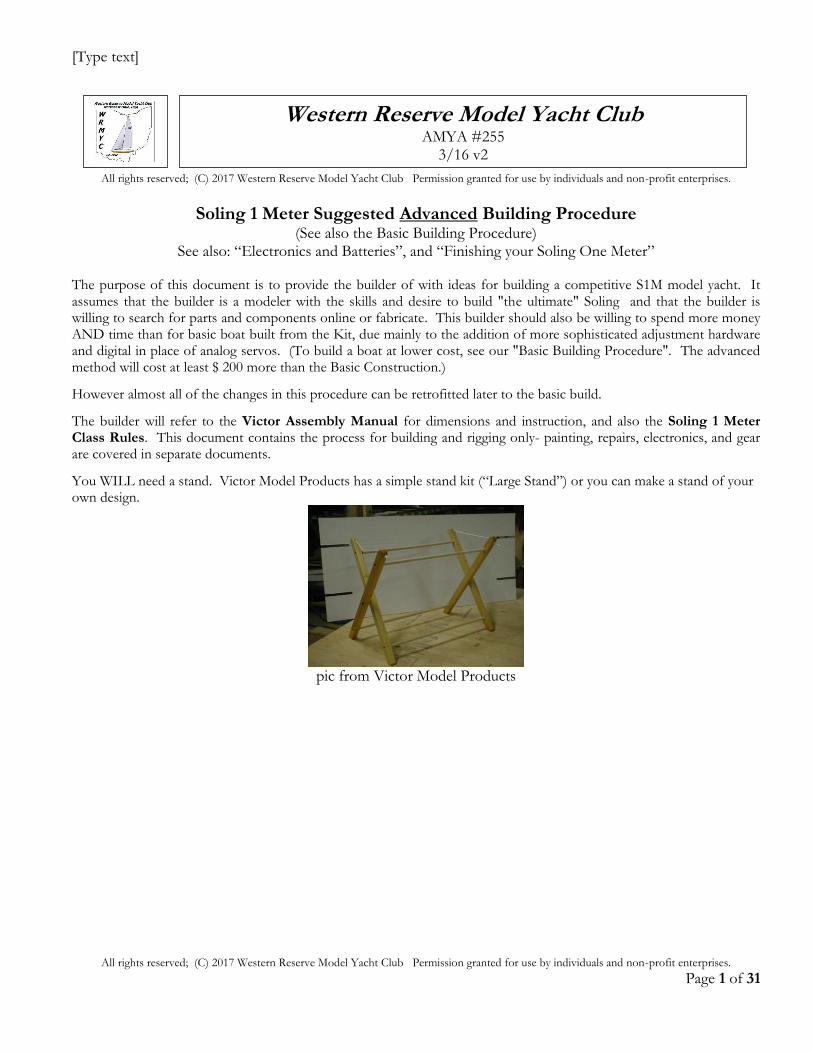
You WILL need a stand. Victor Model Products has a simple stand kit (“Large Stand”) or you can make a stand of your own design.
pic from Victor Model Products
Western Reserve Model Yacht Club AMYA #255
3/16 v2
[Type text]
All rights reserved; (C) 2017 Western Reserve Model Yacht Club Permission granted for use by individuals and non-profit enterprises.
Page 2 of 31
Tools and Supplies Needed:
H = hobby shop R = retail hardware O = online A = auto supply S = sporting goods
H
Exacto Knife O
R
Victor Lower Boat Kit Victor Keel Kit R
Paint, stain or varnish to finish the spars; and for waterproofing
R Needlenose pliers
H Velcro strips (12" length enough)
R Measuring Tape- 6 ft. or longer.
R Large Channelock-type pliers for wire crimping
H Fiberglass cloth 1/2 - 3/4 oz
cloth or tape R
1 Quart Mineral Spirits
H 1/8" ID Carbon Fiber tube
H Disposable epoxy brush (metal-handled paint brush) R
1 Quart MEK
H Thin, and Thickened CA, plus CA DeBonder, CA Accelerator A
Wet/Dry Sandpaper- 220, 600, 1000, 1500 and 2000 grit
O R
Epoxy filler- WEST System #405 OR sawdust, from a wood shop.
R Bandsaw helpful Belt sander helpful R
10 or 12" flat file O R
Quart of WEST Epoxy resin and Hardener (see text- “Adhesives, pg 3)
A Body Filler- Bondo type or Squadron waterproof
H
Saw- (Atlas model saw, or any small saw for cutting wood). Miter box helpful.
H Retail 30-minute Epoxy 5, 10, and 15-Minute Epoxies are not waterproof!!
H Pack Fiberglass cloth- 1/2 - 3/4 oz.
S
6-3/4 lbs. #9 or #8 lead shot (unless buying a pre-made keel) S
80# test spectra braided fishing line- one spool
R MEK (Methyl Ethyl Ketone) Quart- from paint store R
Digital postal scale 25 lb. capacity R
Isopropyl alcohol (to use as a cleaner for epoxy.)
H
Dremel motor tool and cutoff wheel; addl. motor tool accessories are also helpful
R
For Alignment Jig (1) level (2) c-clamps (2) thin sticks/ skewers (2) 1 X 3” boards- 4’ long
R
3/8" chuck drill motor, plus 1/16”, # 30, 3/32”, 1/8”, 3/16”, 11/64”, 13/64”, 9/32” drill bits
H 1/4” square balsa wood- 2'stick
IF flangeless boat- 2 add'l sticks R
3/32" 1/8" Birch Plywood 1 4X6" piece each
H 1/4", 3/8", and 1/2" square basswood- 2' sticks 1 ea.
S
SS Wire and crimps (example: Malin 7 Strand) Order from Bass Pro Shops, Malin # PC60-30 30 ft./ 60 lb. www.basspro.com $4 / 30ft.
Fastenal: https://www.fastenal.com (min 3) 3/32" X 1" Stainless Cotter Pins
SKU: 74295 (8) 1/16" X 3/4" " " "
SKU: 74270 (4) #4 X 1/4" Flat Head Metal Screws
SKU: 72235
R
T-Strip- aluminum strip is available at Home Depot (Reno-T Satin Anodized Aluminum 17/32 in. x 8 ft. 2-1/2 in. Metal T-Shaped Tile Edging Trim) $ 10
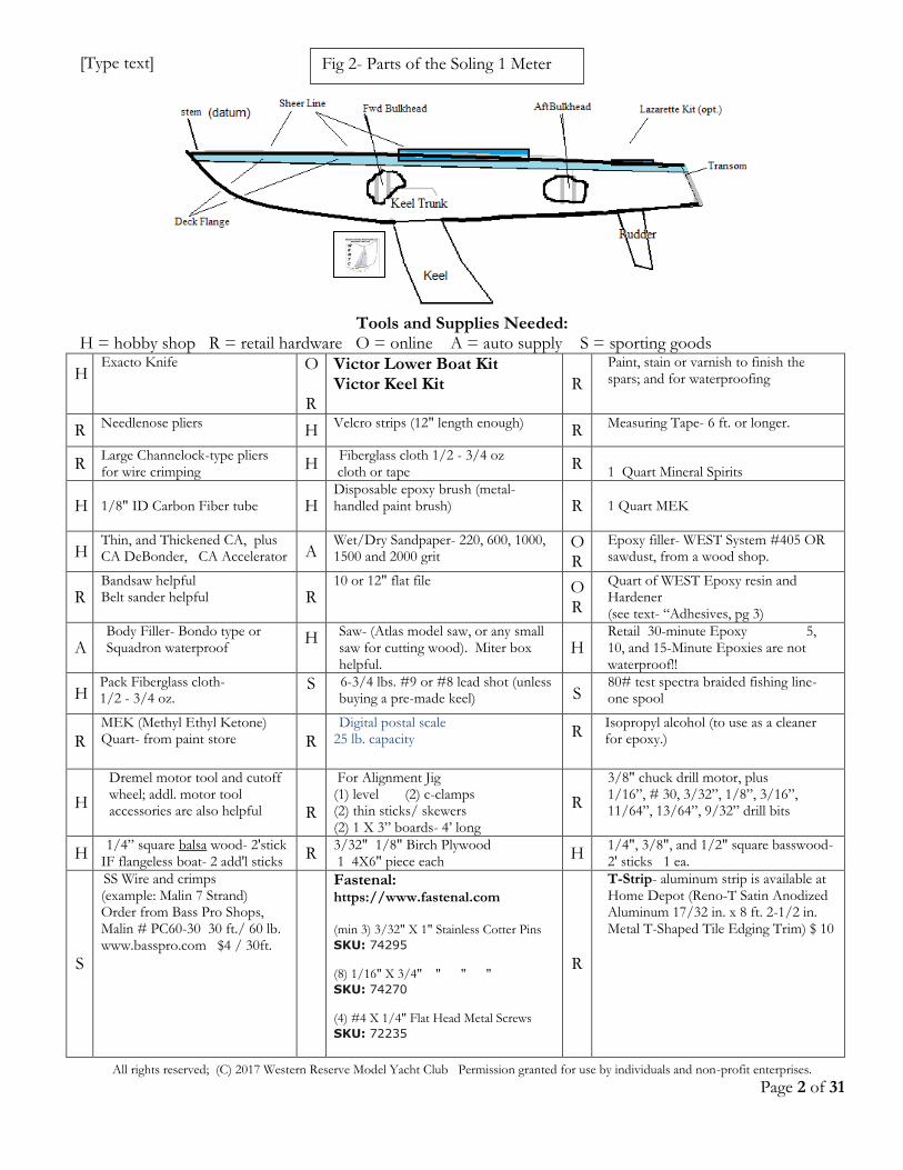
Fig 2- Parts of the Soling 1 Meter
[Type text]
All rights reserved; (C) 2017 Western Reserve Model Yacht Club Permission granted for use by individuals and non-profit enterprises.
Page 3 of 31
O
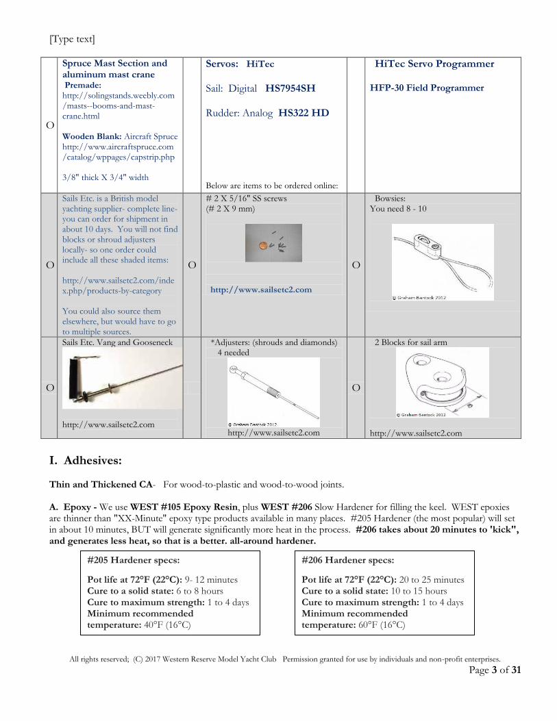
Spruce Mast Section and aluminum mast crane Premade: http://solingstands.weebly.com/masts--booms-and-mast-crane.html Wooden Blank: Aircraft Spruce http://www.aircraftspruce.com/catalog/wppages/capstrip.php 3/8" thick X 3/4" width
Servos: HiTec Sail: Digital HS7954SH Rudder: Analog HS322 HD
Below are items to be ordered online:
HiTec Servo Programmer HFP-30 Field Programmer
O
Sails Etc. is a British model yachting supplier- complete line- you can order for shipment in about 10 days. You will not find blocks or shroud adjusters locally- so one order could include all these shaded items: http://www.sailsetc2.com/index.php/products-by-category You could also source them elsewhere, but would have to go to multiple sources.
O
# 2 X 5/16" SS screws (# 2 X 9 mm)
http://www.sailsetc2.com
O
Bowsies: You need 8 - 10
O
Sails Etc. Vang and Gooseneck
http://www.sailsetc2.com
*Adjusters: (shrouds and diamonds) 4 needed
http://www.sailsetc2.com
O
2 Blocks for sail arm
http://www.sailsetc2.com
I. Adhesives: Thin and Thickened CA- For wood-to-plastic and wood-to-wood joints. A. Epoxy - We use WEST #105 Epoxy Resin, plus WEST #206 Slow Hardener for filling the keel. WEST epoxies are thinner than "XX-Minute" epoxy type products available in many places. #205 Hardener (the most popular) will set in about 10 minutes, BUT will generate significantly more heat in the process. #206 takes about 20 minutes to 'kick", and generates less heat, so that is a better. all-around hardener.
#206 Hardener specs:
Pot life at 72°F (22°C): 20 to 25 minutes Cure to a solid state: 10 to 15 hours Cure to maximum strength: 1 to 4 days Minimum recommended temperature: 60°F (16°C)
#205 Hardener specs:
Pot life at 72°F (22°C): 9- 12 minutes Cure to a solid state: 6 to 8 hours Cure to maximum strength: 1 to 4 days Minimum recommended temperature: 40°F (16°C)
[Type text]
All rights reserved; (C) 2017 Western Reserve Model Yacht Club Permission granted for use by individuals and non-profit enterprises.
Page 4 of 31
WEST epoxies are available online or in marine stores. How much WEST Epoxy will you need??
- 1 boat- quart plus a pint can of Hardener. - 3 or 4 boats, plus Keels take about ½ gallon of resin and a suitable amount of hardener; - 5 or 6 boats at once, get a gallon of #105 Resin and suitable amount of Hardener. (The cost of epoxy is about $30/ boat; lead shot $ 13). Plus get the WEST System mini- pump set (about $18) for precise proportioning and foolproof results
You can also mix your epoxy by weight, using a digital scale (follow directions on Hardener can).
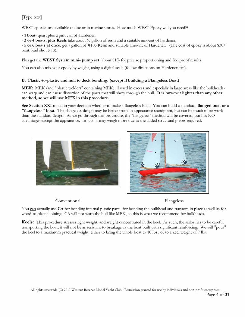
B. Plastic-to-plastic and hull to deck bonding: (except if building a Flangeless Boat)
MEK: MEK (and "plastic welders" containing MEK) if used in excess and especially in large areas like the bulkheads-can warp and can cause distortion of the parts that will show through the hull. It is however lighter than any other method, so we will use MEK in this procedure.
See Section XXI to aid in your decision whether to make a flangeless boat. You can build a standard, flanged boat or a "flangeless" boat. The flangeless design may be better from an appearance standpoint, but can be much more work than the standard design. As we go through this procedure, the "flangeless" method will be covered, but has NO advantages except the appearance. In fact, it may weigh more due to the added structural pieces required.
Conventional Flangeless
You can actually use CA for bonding internal plastic parts, for bonding the bulkhead and transom in place as well as for wood-to-plastic joining. CA will not warp the hull like MEK, so this is what we recommend for bulkheads.
Keels: This procedure stresses light weight, and weight concentrated in the keel. As such, the sailor has to be careful transporting the boat; it will not be as resistant to breakage as the boat built with significant reinforcing. We will "pour" the keel to a maximum practical weight, either to bring the whole boat to 10 lbs., or to a keel weight of 7 lbs.
[Type text]
All rights reserved; (C) 2017 Western Reserve Model Yacht Club Permission granted for use by individuals and non-profit enterprises.
Page 5 of 31
Now on to the building: At each step- read the Kit Assembly Manual covering that portion, then read our procedure. IMPORTANT: IF you are building a flangeless boat, the Class Rules assume that the hull will be 1/4" more forward than if the deck is mounted conventionally. Then for ALL measurements taken from aft of the stem (from datum), you must subtract 1/4" to meet Class Rules. I have converted this for you at applicable steps, but check.
II. Mark the hull for length and keel position.
(Note: Use pencil. Ballpoint, markers, and felt-tips will eventually bleed through styrene plastic.)
A. Trial-fit the deck. Rubber-band the hull-deck assembly together and push the hull tight forward in the deck
tight to the stem. It may help to heat the stem area of the deck and hull using a hair dryer, then push the hull into the deck to better shape it for a tighter fit.
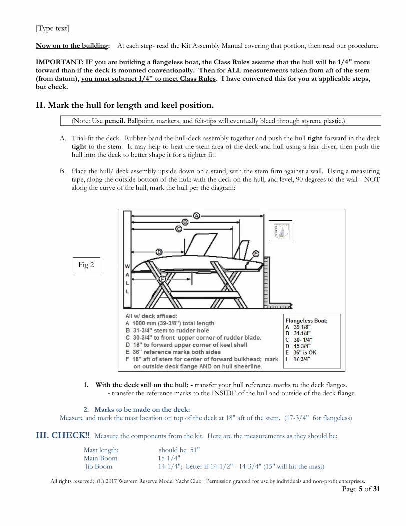
B. Place the hull/ deck assembly upside down on a stand, with the stem firm against a wall. Using a measuring
tape, along the outside bottom of the hull: with the deck on the hull, and level, 90 degrees to the wall-- NOT along the curve of the hull, mark the hull per the diagram:
1. With the deck still on the hull: - transfer your hull reference marks to the deck flanges. - transfer the reference marks to the INSIDE of the hull and outside of the deck flange.
2. Marks to be made on the deck: Measure and mark the mast location on top of the deck at 18" aft of the stem. (17-3/4" for flangeless)
III. CHECK!! Measure the components from the kit. Here are the measurements as they should be:
Mast length: should be 51" Main Boom 15-1/4" Jib Boom 14-1/4"; better if 14-1/2" - 14-3/4" (15" will hit the mast)
Fig 2
[Type text]
All rights reserved; (C) 2017 Western Reserve Model Yacht Club Permission granted for use by individuals and non-profit enterprises.
Page 6 of 31
You can just use a 1/2" X 14-1/2" wooden dowel to make a longer jib boom.
IV. Centerlines- Locate and mark the centerlines of the boat and the interior bulkheads.
A. Hull Centerline: Mark a centerline on the inside of the HULL from just ahead of the keel spar cutout to the stern. This can be done several ways: one good method is to sharpen a standard wooden pencil, allow it to roll to the center bottom inside the hull- the point will be on center. Pencil a center point forward and another aft of the keel slot, then connect the two, and extend this line the length of the hull.
NOTE: the keel slot and/ or rudder hole are not always perfectly centered from Victor. Check!!
B. Deck Centerline: newer (approx. 2013 and later) Kits have a deck with centerline (faintly) molded in.
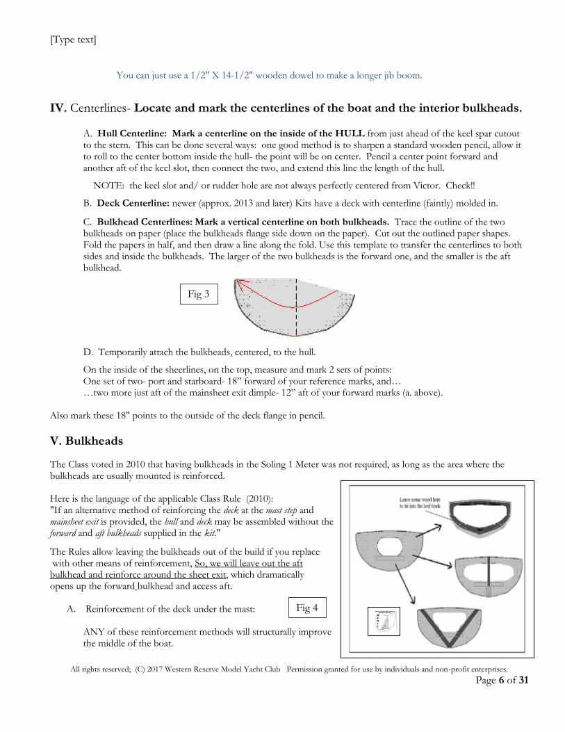
C. Bulkhead Centerlines: Mark a vertical centerline on both bulkheads. Trace the outline of the two bulkheads on paper (place the bulkheads flange side down on the paper). Cut out the outlined paper shapes. Fold the papers in half, and then draw a line along the fold. Use this template to transfer the centerlines to both sides and inside the bulkheads. The larger of the two bulkheads is the forward one, and the smaller is the aft bulkhead.
D. Temporarily attach the bulkheads, centered, to the hull.
On the inside of the sheerlines, on the top, measure and mark 2 sets of points: One set of two- port and starboard- 18” forward of your reference marks, and… …two more just aft of the mainsheet exit dimple- 12” aft of your forward marks (a. above).
Also mark these 18" points to the outside of the deck flange in pencil.
V. Bulkheads
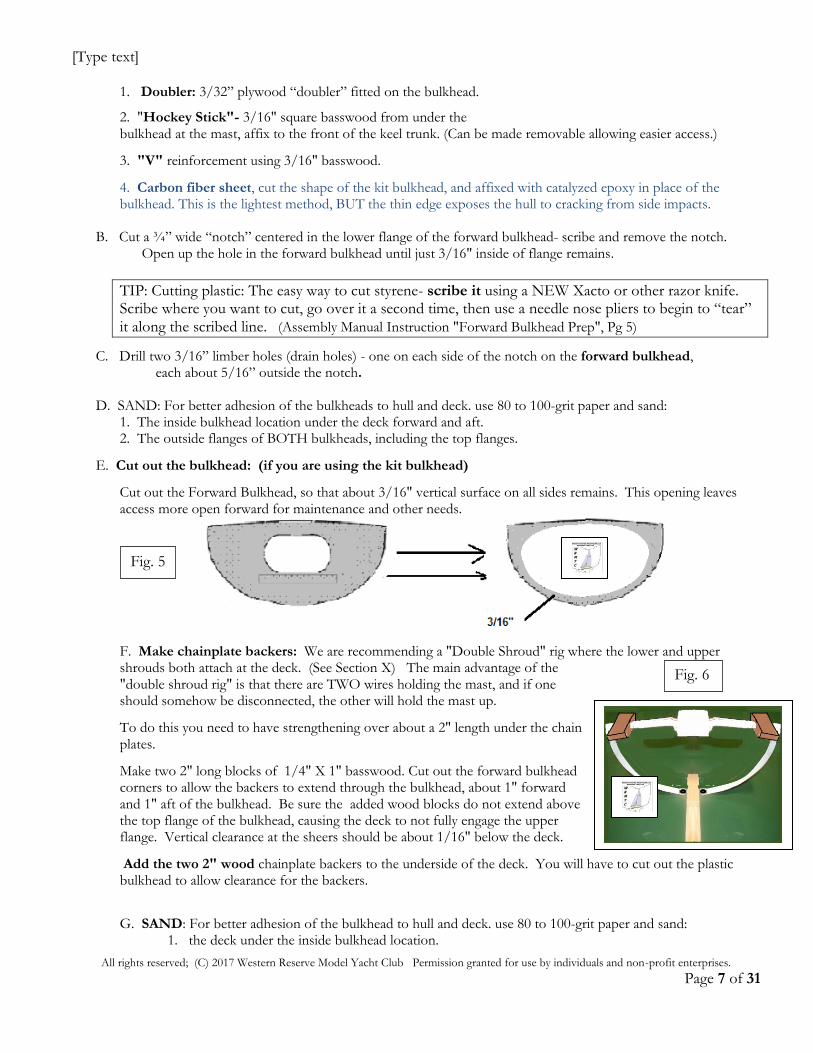
The Class voted in 2010 that having bulkheads in the Soling 1 Meter was not required, as long as the area where the bulkheads are usually mounted is reinforced. Here is the language of the applicable Class Rule (2010): "If an alternative method of reinforcing the deck at the mast step and mainsheet exit is provided, the hull and deck may be assembled without the forward and aft bulkheads supplied in the kit."
The Rules allow leaving the bulkheads out of the build if you replace with other means of reinforcement, So, we will leave out the aft bulkhead and reinforce around the sheet exit, which dramatically opens up the forward bulkhead and access aft.
A. Reinforcement of the deck under the mast: ANY of these reinforcement methods will structurally improve the middle of the boat.
Fig 3
Fig 4
[Type text]
All rights reserved; (C) 2017 Western Reserve Model Yacht Club Permission granted for use by individuals and non-profit enterprises.
Page 7 of 31
1. Doubler: 3/32” plywood “doubler” fitted on the bulkhead.
2. "Hockey Stick"- 3/16" square basswood from under the bulkhead at the mast, affix to the front of the keel trunk. (Can be made removable allowing easier access.)
3. "V" reinforcement using 3/16" basswood.
4. Carbon fiber sheet, cut the shape of the kit bulkhead, and affixed with catalyzed epoxy in place of the bulkhead. This is the lightest method, BUT the thin edge exposes the hull to cracking from side impacts.
B. Cut a ¾” wide “notch” centered in the lower flange of the forward bulkhead- scribe and remove the notch. Open up the hole in the forward bulkhead until just 3/16" inside of flange remains.
TIP: Cutting plastic: The easy way to cut styrene- scribe it using a NEW Xacto or other razor knife. Scribe where you want to cut, go over it a second time, then use a needle nose pliers to begin to “tear” it along the scribed line. (Assembly Manual Instruction "Forward Bulkhead Prep", Pg 5)
C. Drill two 3/16” limber holes (drain holes) - one on each side of the notch on the forward bulkhead, each about 5/16” outside the notch. D. SAND: For better adhesion of the bulkheads to hull and deck. use 80 to 100-grit paper and sand: 1. The inside bulkhead location under the deck forward and aft. 2. The outside flanges of BOTH bulkheads, including the top flanges.
E. Cut out the bulkhead: (if you are using the kit bulkhead)
Cut out the Forward Bulkhead, so that about 3/16" vertical surface on all sides remains. This opening leaves access more open forward for maintenance and other needs.
F. Make chainplate backers: We are recommending a "Double Shroud" rig where the lower and upper shrouds both attach at the deck. (See Section X) The main advantage of the "double shroud rig" is that there are TWO wires holding the mast, and if one should somehow be disconnected, the other will hold the mast up.
To do this you need to have strengthening over about a 2" length under the chain plates.
Make two 2" long blocks of 1/4" X 1" basswood. Cut out the forward bulkhead corners to allow the backers to extend through the bulkhead, about 1" forward and 1" aft of the bulkhead. Be sure the added wood blocks do not extend above the top flange of the bulkhead, causing the deck to not fully engage the upper flange. Vertical clearance at the sheers should be about 1/16" below the deck.
Add the two 2" wood chainplate backers to the underside of the deck. You will have to cut out the plastic bulkhead to allow clearance for the backers.
G. SAND: For better adhesion of the bulkhead to hull and deck. use 80 to 100-grit paper and sand: 1. the deck under the inside bulkhead location.
Fig. 6
Fig. 5

[Type text]
All rights reserved; (C) 2017 Western Reserve Model Yacht Club Permission granted for use by individuals and non-profit enterprises.
Page 8 of 31
2. the outside flanges of the bulkhead, including the top flange. top flanges. 3. The tops of the chainplate backers. H. Add a cross beam to the forward bulkhead.
Cut and shape a “beam” out of (1/4”) balsawood, to fit under the upper bulkhead flange, against the chainplate backers. Shape it to fit the upper bulkhead flange. CA into the bulkhead.
I. Cut two right angle "T" supports again out of balsawood, to mount under the flange- one aft and one ahead of the bulkhead.
Use CA to attach the styrene mast support in the kit then CA two right angle supports to the bulkhead, beam, and styrene mast support.
J. Trial fit forward Bulkhead- with the “open”- flanges side facing AFT. 1. Align the forward bulkhead at the 18" marks (1 & 2 above) on the hull at the top corners of the bulkhead (BOTH sides- equal distance forward of your reference mark), so the bulkhead is square to the deck. Once located, use tape (no glue) to hold the bulkhead in place, on the centerline and square to the line of the boat. 2. Snap the deck to the hull, sight through the open transom, check that the forward Bulkhead is centered- and the “gap” between the top of the bulkhead against the deck port and starboard deck is about the same. Make adjustments to reposition the forward bulkhead so it is (a) square, (b) meets the deck evenly across the top. Retape. 3. Look through the hatch opening, and verify that the centerline of the forward bulkhead, and centerline on the hull, match.
VI. Keel Trunk
Fig.8
Fig. 8
Fig. 7
[Type text]
All rights reserved; (C) 2017 Western Reserve Model Yacht Club Permission granted for use by individuals and non-profit enterprises.
Page 9 of 31
A. Assemble the keel trunk, per the Victor Assembly Manual Pg 4. Leave the top piece off the trunk for now.
We recommend assembling one side of the keel trunk with the keel spar laying in it for fit. Be careful that you do not glue the spar to the trunk!! Then, add the second side and CA in place. Don't make the fit too tight, you will need to add glue in there when you bond the keel in place.
B. After a few minutes- wipe any excess CA from the keel trunk. MAKE SURE there is no wet CA in the trunk!
C. Finally, use a belt or disc sander or a flat sanding board, made by spray-gluing a piece of 80- 120 grit sandpaper to a piece of plywood, to sand the edges of the keel trunk flat and square.
D. Measure and draw a vertical centerline on the forward top edge and in the small vertical aft edge of your assembled keel trunk.
Test fit the keel trunk/ forward bulkhead assembly into the hull. Make sure the keel trunk fits tightly on the hull (over the keel slot) and that the bulkhead is centered on the centerline of the hull.
At this time, IF the keel slot is not centered, you can use your Dremel and a mounted abrasive point to
open it up where needed.
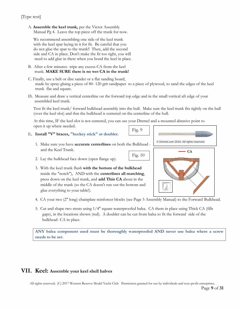
E. Install "V" braces, "hockey stick" or doubler.
1. Make sure you have accurate centerlines on both the Bulkhead -
and the Keel Trunk.
2. Lay the bulkhead face down (open flange up).
3. With the keel trunk flush with the bottom of the bulkhead (fit
inside the "notch"), AND with the centerlines all matching,
press down on the keel trunk, and add Thin CA about in the
middle of the trunk (so the CA doesn't run out the bottom and
glue everything to your table!).
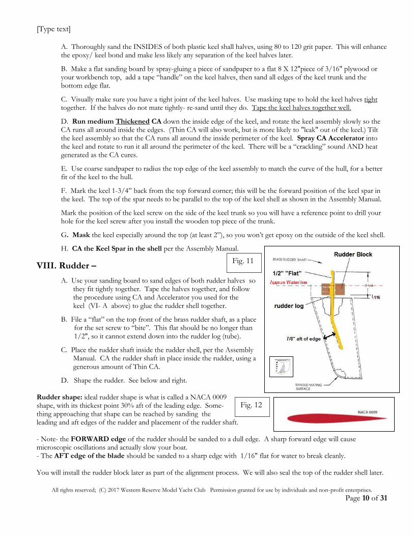
4. CA your two (2" long) chainplate reinforcer blocks (see Page 5 Assembly Manual) to the Forward Bulkhead.
5. Cut and shape two struts using 1/4" square waterproofed balsa. CA them in place using Thick CA (fills
gaps), in the locations shown (red). A doubler can be cut from balsa to fit the forward side of the
bulkhead- CA in place.
ANY balsa component used must be thoroughly waterproofed AND never use balsa where a screw
needs to be set.
VII. Keel: Assemble your keel shell halves
Fig. 9
© Dremel.com 2016. All rights reserved.
Fig. 10
[Type text]
All rights reserved; (C) 2017 Western Reserve Model Yacht Club Permission granted for use by individuals and non-profit enterprises.
Page 10 of 31
A. Thoroughly sand the INSIDES of both plastic keel shall halves, using 80 to 120 grit paper. This will enhance the epoxy/ keel bond and make less likely any separation of the keel halves later.
B. Make a flat sanding board by spray-gluing a piece of sandpaper to a flat 8 X 12"piece of 3/16" plywood or your workbench top, add a tape “handle” on the keel halves, then sand all edges of the keel trunk and the bottom edge flat. C. Visually make sure you have a tight joint of the keel halves. Use masking tape to hold the keel halves tight together. If the halves do not mate tightly- re-sand until they do. Tape the keel halves together well.
D. Run medium Thickened CA down the inside edge of the keel, and rotate the keel assembly slowly so the CA runs all around inside the edges. (Thin CA will also work, but is more likely to "leak" out of the keel.) Tilt the keel assembly so that the CA runs all around the inside perimeter of the keel. Spray CA Accelerator into the keel and rotate to run it all around the perimeter of the keel. There will be a “crackling” sound AND heat generated as the CA cures.
E. Use coarse sandpaper to radius the top edge of the keel assembly to match the curve of the hull, for a better fit of the keel to the hull.
F. Mark the keel 1-3/4” back from the top forward corner; this will be the forward position of the keel spar in the keel. The top of the spar needs to be parallel to the top of the keel shell as shown in the Assembly Manual.
Mark the position of the keel screw on the side of the keel trunk so you will have a reference point to drill your hole for the keel screw after you install the wooden top piece of the trunk.
G. Mask the keel especially around the top (at least 2”), so you won’t get epoxy on the outside of the keel shell.
H. CA the Keel Spar in the shell per the Assembly Manual.
VIII. Rudder –
A. Use your sanding board to sand edges of both rudder halves so they fit tightly together. Tape the halves together, and follow the procedure using CA and Accelerator you used for the keel (VI- A above) to glue the rudder shell together.
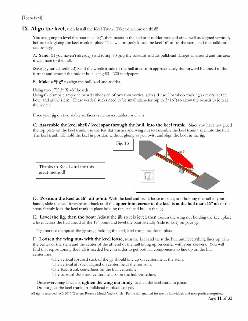
B. File a “flat” on the top front of the brass rudder shaft, as a place for the set screw to “bite”. This flat should be no longer than 1/2", so it cannot extend down into the rudder log (tube).
C. Place the rudder shaft inside the rudder shell, per the Assembly Manual. CA the rudder shaft in place inside the rudder, using a generous amount of Thin CA.
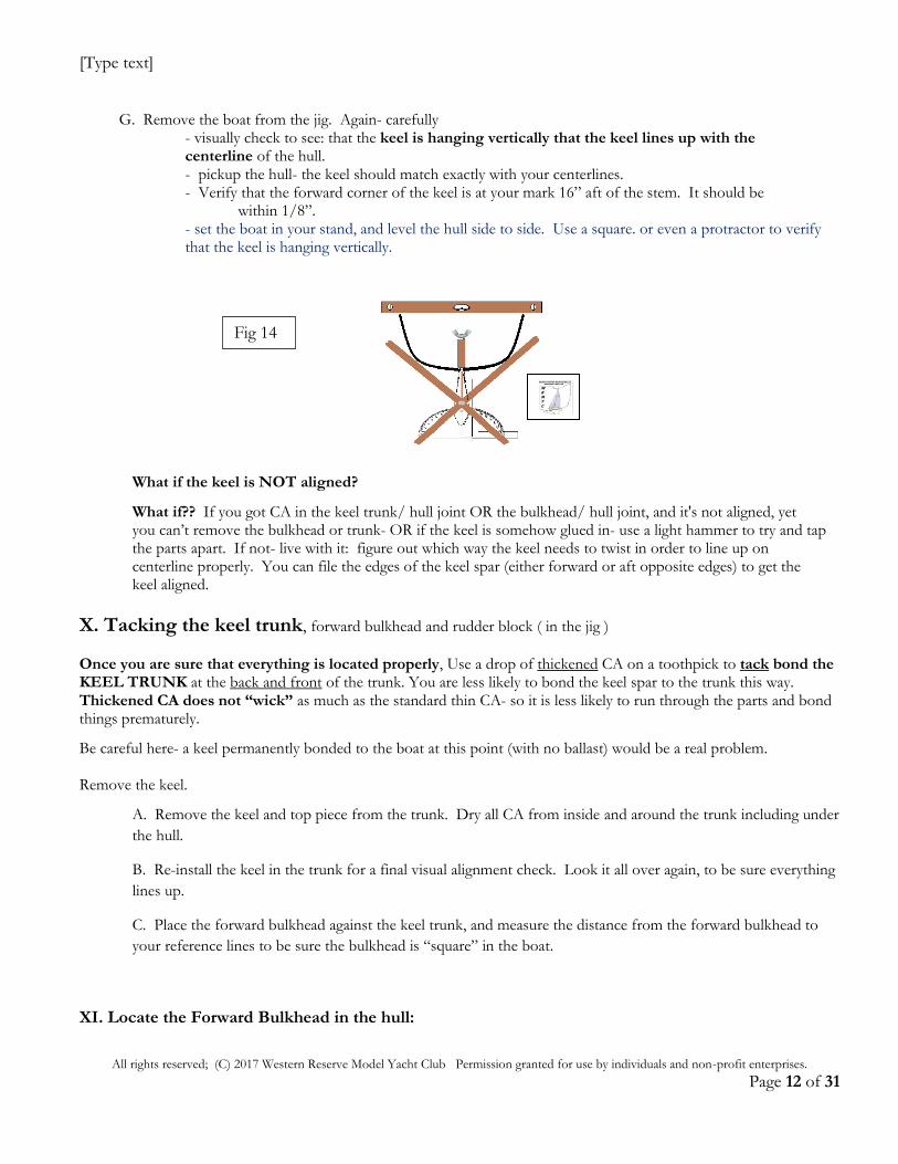
D. Shape the rudder. See below and right. Rudder shape: ideal rudder shape is what is called a NACA 0009 shape, with its thickest point 30% aft of the leading edge. Some- thing approaching that shape can be reached by sanding the leading and aft edges of the rudder and placement of the rudder shaft. - Note- the FORWARD edge of the rudder should be sanded to a dull edge. A sharp forward edge will cause microscopic oscillations and actually slow your boat. - The AFT edge of the blade should be sanded to a sharp edge with 1/16" flat for water to break cleanly. You will install the rudder block later as part of the alignment process. We will also seal the top of the rudder shell later.
Fig. 11
Fig. 12
[Type text]
All rights reserved; (C) 2017 Western Reserve Model Yacht Club Permission granted for use by individuals and non-profit enterprises.
Page 11 of 31
IX. Align the keel, then install the Keel Trunk. Take your time on this!!!
You are going to level the boat in a “jig”, then position the keel and rudder fore and aft as well as aligned vertically before tack-gluing the keel trunk in place. This will properly locate the keel 16” aft of the stem, and the bulkhead accordingly.
A. Sand: (If you haven’t already) sand (using 80 grit) the forward and aft bulkhead flanges all around and the area it will mate to the hull.
(Saving your centerlines!) Sand the whole inside of the hull area from approximately the forward bulkhead to the former and around the rudder hole using 80 - 220 sandpaper.
B. Make a “jig” to align the hull, keel and rudder.
Using two 1”X 3“ X 48” boards… Using C- clamps clamp one board either side of two thin vertical sticks (I use 2 bamboo cooking skewers) at the bow, and at the stern. These vertical sticks need to be small diameter (up to 3/16”) to allow the boards to join at the center. Place your jig on two stable surfaces- sawhorses, tables, or chairs.
C. Assemble the keel shell/ keel spar through the hull, into the keel trunk. Since you have not glued the top plate on the keel trunk, use the Kit flat washer and wing nut to assemble the keel trunk/ keel into the hull. The keel trunk will hold the keel in position without gluing as you twist and align the boat in the jig.
D. Position the keel at 16" aft point: With the keel and trunk loose in place, and holding the hull in your hands, slide the keel forward and back until the upper front corner of the keel is at the hull mark 16” aft of the stem. Gently lock the keel trunk in place holding the keel and hull in the jig.
E. Level the jig, then the boat: Adjust the jib so it is level, then loosen the wing nut holding the keel, place
a level across the hull ahead of the 18" point and level the boat laterally (side to side) on your jig.
Tighten the clamps of the jig snug, holding the keel, keel trunk, rudder in place.
F. Loosen the wing nut- with the keel loose, turn the keel and twist the hull until everything lines up with
the center of the stem and the center of the aft end of the hull lining up on center with your skewers. You will find that repositioning the hull is needed here, in order to get both all components to line up on the hull centerlines.
-The vertical forward stick of the jig should line up on centerline at the stem. -The vertical aft stick aligned on centerline at the transom. -The Keel trunk centerlines on the hull centerline. -The forward Bulkhead centerline also on the hull centerline.
Once everything lines up, tighten the wing nut firmly, to lock the keel trunk in place. Do not glue the keel trunk, or bulkhead in place just yet.
Thanks to Rick Laird for this great method!
Fig. 13
[Type text]
All rights reserved; (C) 2017 Western Reserve Model Yacht Club Permission granted for use by individuals and non-profit enterprises.
Page 12 of 31
G. Remove the boat from the jig. Again- carefully - visually check to see: that the keel is hanging vertically that the keel lines up with the centerline of the hull. - pickup the hull- the keel should match exactly with your centerlines. - Verify that the forward corner of the keel is at your mark 16” aft of the stem. It should be within 1/8”. - set the boat in your stand, and level the hull side to side. Use a square. or even a protractor to verify that the keel is hanging vertically.
What if the keel is NOT aligned?
What if?? If you got CA in the keel trunk/ hull joint OR the bulkhead/ hull joint, and it's not aligned, yet you can’t remove the bulkhead or trunk- OR if the keel is somehow glued in- use a light hammer to try and tap the parts apart. If not- live with it: figure out which way the keel needs to twist in order to line up on centerline properly. You can file the edges of the keel spar (either forward or aft opposite edges) to get the keel aligned.
X. Tacking the keel trunk, forward bulkhead and rudder block ( in the jig )
Once you are sure that everything is located properly, Use a drop of thickened CA on a toothpick to tack bond the KEEL TRUNK at the back and front of the trunk. You are less likely to bond the keel spar to the trunk this way. Thickened CA does not “wick” as much as the standard thin CA- so it is less likely to run through the parts and bond things prematurely.
Be careful here- a keel permanently bonded to the boat at this point (with no ballast) would be a real problem. Remove the keel.
A. Remove the keel and top piece from the trunk. Dry all CA from inside and around the trunk including under
the hull.
B. Re-install the keel in the trunk for a final visual alignment check. Look it all over again, to be sure everything
lines up.
C. Place the forward bulkhead against the keel trunk, and measure the distance from the forward bulkhead to
your reference lines to be sure the bulkhead is “square” in the boat.
XI. Locate the Forward Bulkhead in the hull:
Fig 14
[Type text]
All rights reserved; (C) 2017 Western Reserve Model Yacht Club Permission granted for use by individuals and non-profit enterprises.
Page 13 of 31
A. Place the deck on the hull. Use rubber bands to hold the deck in place pushed hard forward.
B. LOOK from behind the boat through the transom at the forward Bulkhead. You will be able to clearly see
the “fit” of the forward bulkhead to the deck. The bulkhead should fit squarely- you should see pretty close to
100% contact all around the bulkhead at the hull and the deck, with small (1/16” or so) gaps at the top corners
of the bulkhead.
C. Remove the deck.
D. Bond the forward Bulkhead to the Keel Trunk using CA. Leave the top 1-1/2” on each side un-bonded
to the hull until later.
E. Fully bond the keel trunk in place using thin CA.
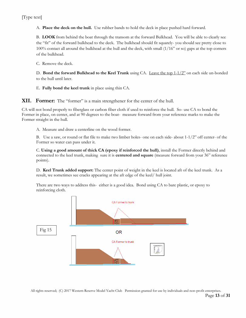
XII. Former: The “former” is a main strengthener for the center of the hull.
CA will not bond properly to fiberglass or carbon fiber cloth if used to reinforce the hull. So- use CA to bond the Former in place, on center, and at 90 degrees to the boat- measure forward from your reference marks to make the Former straight in the hull. A. Measure and draw a centerline on the wood former.
B. Use a saw, or round or flat file to make two limber holes- one on each side- about 1-1/2” off center- of the Former so water can pass under it.
C. Using a good amount of thick CA (epoxy if reinforced the hull), install the Former directly behind and connected to the keel trunk, making sure it is centered and square (measure forward from your 36” reference points). D. Keel Trunk added support: The center point of weight in the keel is located aft of the keel trunk. As a result, we sometimes see cracks appearing at the aft edge of the keel/ hull joint. There are two ways to address this- either is a good idea. Bond using CA to bare plastic, or epoxy to reinforcing cloth.
Fig 15
[Type text]
All rights reserved; (C) 2017 Western Reserve Model Yacht Club Permission granted for use by individuals and non-profit enterprises.
Page 14 of 31
XIII. Hull Reinforcement (optional) A. Rough up the area around the keel trunk, and the forward bulkhead flange using 80-grit sandpaper. B. Wipe the area using isopropyl alcohol and allow to dry. C. Cut four pieces of lightweight (1/2 to 3/4 oz.) fiberglass cloth to 4" X 5", using your Exacto knife. B. Catalyze 2 -3 oz. of WEST epoxy resin. C. Lay the cloth pieces into the hull, overlapping UP the sides of the keel trunk, and overlapping the flange of the forward bulkhead. D. Using an epoxy brush, spread the epoxy resin over the area. Use an old credit card or an automotive filler spreader to "squeegee" any excess resin and air bubbles out of the cloth. Allow to cure overnight.
XIV. Deck Reinforcement
Snap the deck in place. A. Locate and drill pilot holes for the shroud attachments at the chainplates centered 18-1/8" aft of the stem (17-7/8" if a flangeless boat).
1. IF using cotter pins, the pilot holes need to allow the pins to drop in place. 2. If using threaded fasteners- the pilot is the size of the “root”- 1/16” pilot is adequate for most threaded fasteners such as eye screws. 3. If using T-strip chainplates (See XV) you can drill 1/16" pilot holes through the t-strip. and then match those through the deck into the backing wood. Then, follow with clearance holes to allow the screws to pass through the t-strip- use # 30 drill bit.
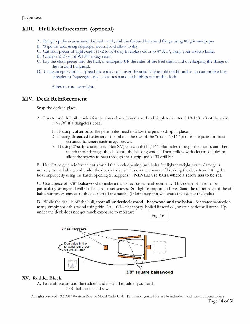
B. Use CA to glue reinforcement around the hatch opening (use balsa for lighter weight, water damage is unlikely to the balsa wood under the deck)- these will lessen the chance of breaking the deck from lifting the boat improperly using the hatch opening (it happens!). NEVER use balsa where a screw has to be set.
C. Use a piece of 3/8” balsawood to make a mainsheet cross-reinforcement. This does not need to be particularly strong and will not be used to set screws. So- light is important here. Sand the upper edge of the aft balsa reinforcer curved to the deck aft of the hatch. (If left straight it will crack the deck at the ends.)
D. While the deck is off the hull, treat all underdeck wood - basswood and the balsa - for water protection- many simply soak this wood using thin CA. OR- clear spray, boiled linseed oil, or stain sealer will work. Up under the deck does not get much exposure to moisture.
XV. Rudder Block A. To reinforce around the rudder, and install the rudder you need: 3/8" balsa stick and saw
Fig. 16
[Type text]
All rights reserved; (C) 2017 Western Reserve Model Yacht Club Permission granted for use by individuals and non-profit enterprises.
Page 15 of 31
3/16" drill bit and drill motor Hobby Grade (thick) epoxy A piece of plastic bag Isopropyl Alcohol, and paper towels to clean up. 80-100 Sandpaper B. Sand and shape the rudder block to fit the hull. C. Rough the inside hull area around the rudder hole using 80- 100 grit sandpaper. D. Drill a 3/16" hole at the correct location for the rudder shaft. The existing hole may/ may not be accurate. E. Install the keel into the keel trunk, using the wing nut and washer.
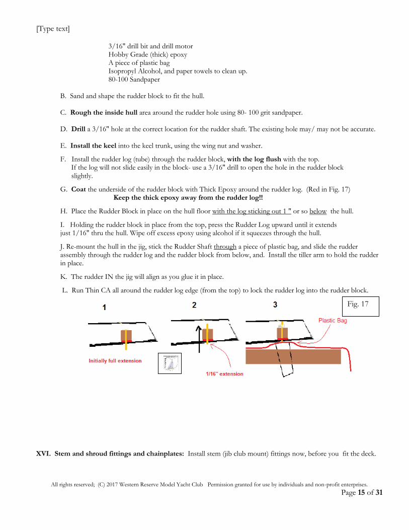
F. Install the rudder log (tube) through the rudder block, with the log flush with the top. If the log will not slide easily in the block- use a 3/16" drill to open the hole in the rudder block slightly.
G. Coat the underside of the rudder block with Thick Epoxy around the rudder log. (Red in Fig. 17) Keep the thick epoxy away from the rudder log!!
H. Place the Rudder Block in place on the hull floor with the log sticking out 1 " or so below the hull.
I. Holding the rudder block in place from the top, press the Rudder Log upward until it extends just 1/16" thru the hull. Wipe off excess epoxy using alcohol if it squeezes through the hull. J. Re-mount the hull in the jig, stick the Rudder Shaft through a piece of plastic bag, and slide the rudder assembly through the rudder log and the rudder block from below, and. Install the tiller arm to hold the rudder in place.
K. The rudder IN the jig will align as you glue it in place.
L. Run Thin CA all around the rudder log edge (from the top) to lock the rudder log into the rudder block.
XVI. Stem and shroud fittings and chainplates: Install stem (jib club mount) fittings now, before you fit the deck.
Fig. 17
[Type text]
All rights reserved; (C) 2017 Western Reserve Model Yacht Club Permission granted for use by individuals and non-profit enterprises.
Page 16 of 31
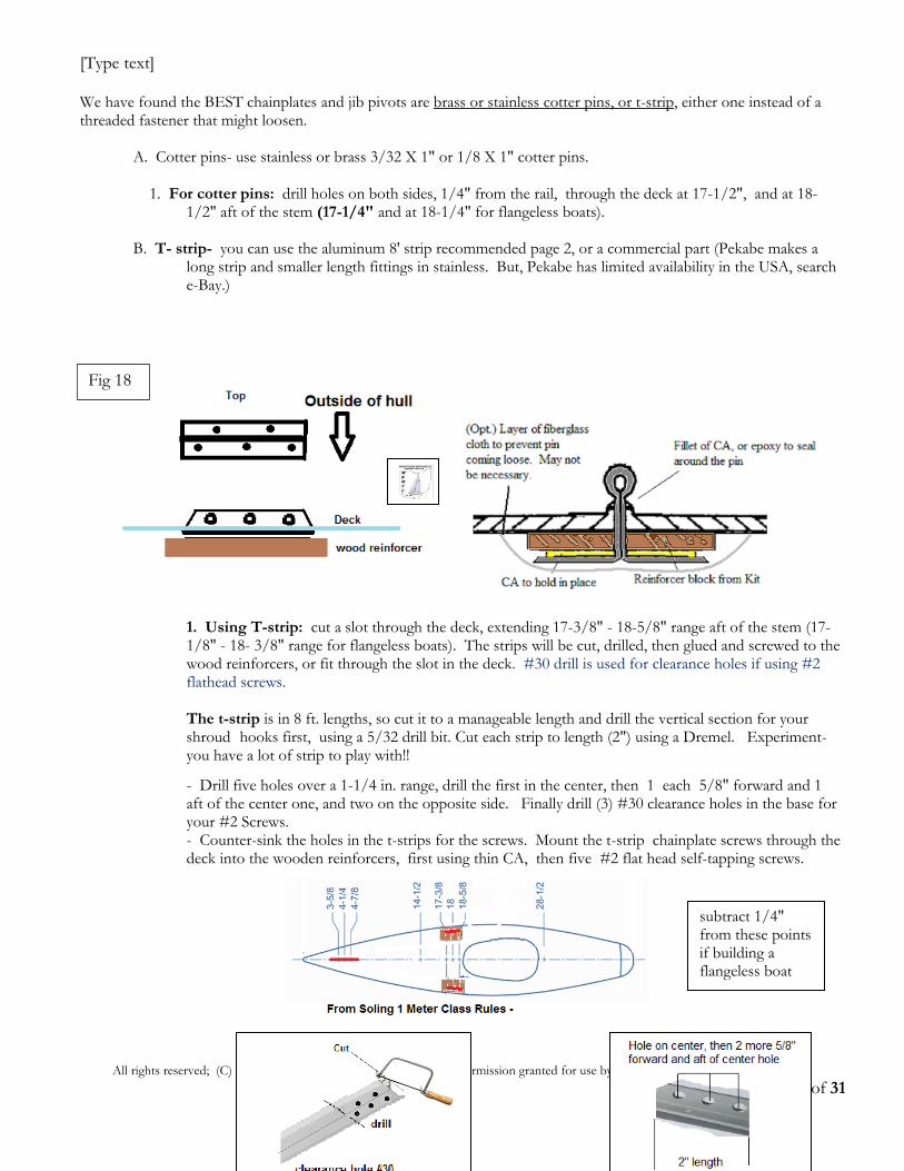
We have found the BEST chainplates and jib pivots are brass or stainless cotter pins, or t-strip, either one instead of a threaded fastener that might loosen. A. Cotter pins- use stainless or brass 3/32 X 1" or 1/8 X 1" cotter pins. 1. For cotter pins: drill holes on both sides, 1/4" from the rail, through the deck at 17-1/2", and at 18- 1/2" aft of the stem (17-1/4" and at 18-1/4" for flangeless boats). B. T- strip- you can use the aluminum 8' strip recommended page 2, or a commercial part (Pekabe makes a long strip and smaller length fittings in stainless. But, Pekabe has limited availability in the USA, search e-Bay.)
1. Using T-strip: cut a slot through the deck, extending 17-3/8" - 18-5/8" range aft of the stem (17- 1/8" - 18- 3/8" range for flangeless boats). The strips will be cut, drilled, then glued and screwed to the wood reinforcers, or fit through the slot in the deck. #30 drill is used for clearance holes if using #2 flathead screws. The t-strip is in 8 ft. lengths, so cut it to a manageable length and drill the vertical section for your shroud hooks first, using a 5/32 drill bit. Cut each strip to length (2") using a Dremel. Experiment- you have a lot of strip to play with!!
- Drill five holes over a 1-1/4 in. range, drill the first in the center, then 1 each 5/8" forward and 1 aft of the center one, and two on the opposite side. Finally drill (3) #30 clearance holes in the base for your #2 Screws. - Counter-sink the holes in the t-strips for the screws. Mount the t-strip chainplate screws through the deck into the wooden reinforcers, first using thin CA, then five #2 flat head self-tapping screws.
Fig 18
subtract 1/4" from these points if building a flangeless boat
[Type text]
All rights reserved; (C) 2017 Western Reserve Model Yacht Club Permission granted for use by individuals and non-profit enterprises.
Page 17 of 31
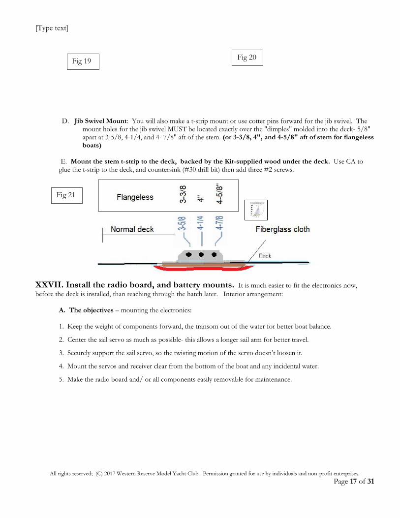
D. Jib Swivel Mount: You will also make a t-strip mount or use cotter pins forward for the jib swivel. The mount holes for the jib swivel MUST be located exactly over the "dimples" molded into the deck- 5/8" apart at 3-5/8, 4-1/4, and 4- 7/8" aft of the stem. (or 3-3/8, 4", and 4-5/8" aft of stem for flangeless boats)
E. Mount the stem t-strip to the deck, backed by the Kit-supplied wood under the deck. Use CA to glue the t-strip to the deck, and countersink (#30 drill bit) then add three #2 screws.
XXVII. Install the radio board, and battery mounts. It is much easier to fit the electronics now,
before the deck is installed, than reaching through the hatch later. Interior arrangement: A. The objectives – mounting the electronics: 1. Keep the weight of components forward, the transom out of the water for better boat balance.
2. Center the sail servo as much as possible- this allows a longer sail arm for better travel.
3. Securely support the sail servo, so the twisting motion of the servo doesn’t loosen it.
4. Mount the servos and receiver clear from the bottom of the boat and any incidental water.
5. Make the radio board and/ or all components easily removable for maintenance.
Fig 19
Fig 21
Fig 20
[Type text]
All rights reserved; (C) 2017 Western Reserve Model Yacht Club Permission granted for use by individuals and non-profit enterprises.
Page 18 of 31
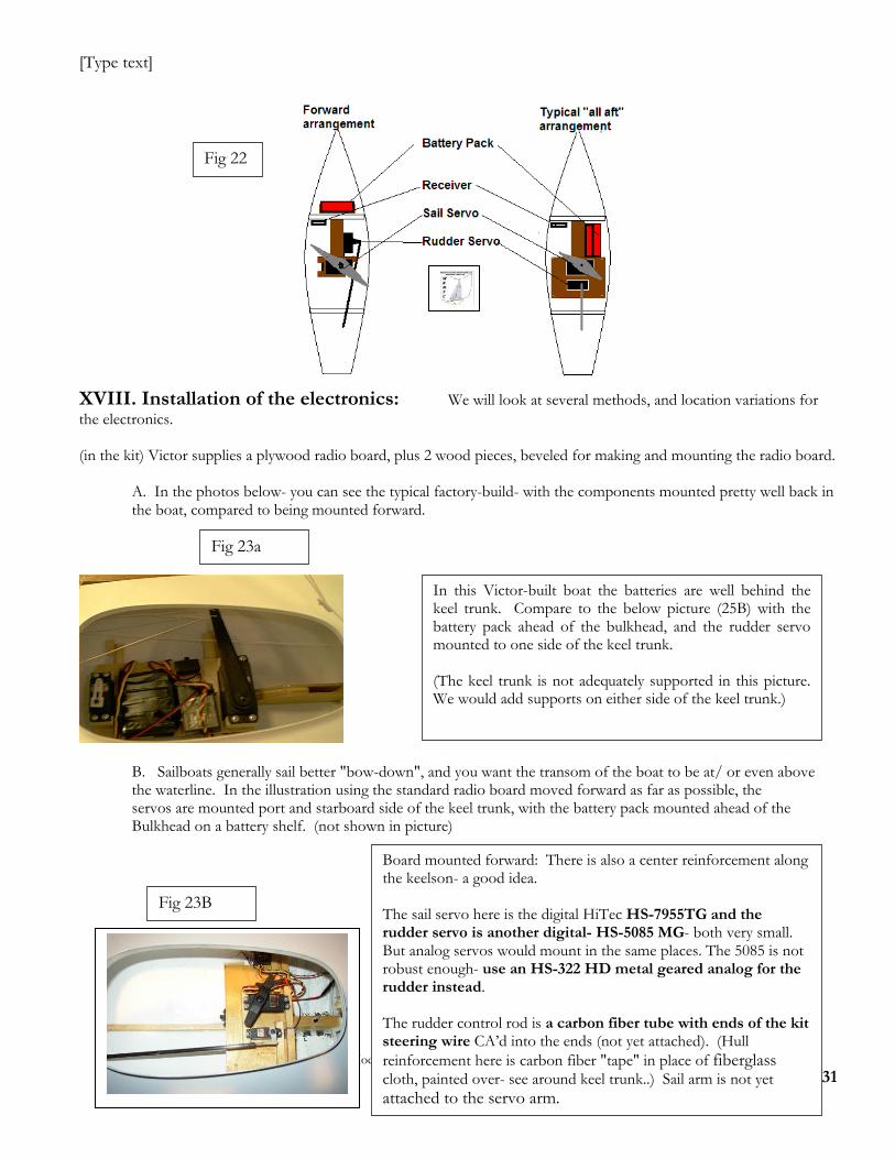
XVIII. Installation of the electronics: We will look at several methods, and location variations for
the electronics. (in the kit) Victor supplies a plywood radio board, plus 2 wood pieces, beveled for making and mounting the radio board. A. In the photos below- you can see the typical factory-build- with the components mounted pretty well back in the boat, compared to being mounted forward.
B. Sailboats generally sail better "bow-down", and you want the transom of the boat to be at/ or even above the waterline. In the illustration using the standard radio board moved forward as far as possible, the servos are mounted port and starboard side of the keel trunk, with the battery pack mounted ahead of the Bulkhead on a battery shelf. (not shown in picture)
Board mounted forward: There is also a center reinforcement along the keelson- a good idea. The sail servo here is the digital HiTec HS-7955TG and the rudder servo is another digital- HS-5085 MG- both very small. But analog servos would mount in the same places. The 5085 is not robust enough- use an HS-322 HD metal geared analog for the rudder instead. The rudder control rod is a carbon fiber tube with ends of the kit steering wire CA’d into the ends (not yet attached). (Hull
reinforcement here is carbon fiber "tape" in place of fiberglass cloth, painted over- see around keel trunk..) Sail arm is not yet
attached to the servo arm.
Fig 23B
Fig 22
In this Victor-built boat the batteries are well behind the keel trunk. Compare to the below picture (25B) with the battery pack ahead of the bulkhead, and the rudder servo mounted to one side of the keel trunk. (The keel trunk is not adequately supported in this picture. We would add supports on either side of the keel trunk.)
Fig 23a
[Type text]
All rights reserved; (C) 2017 Western Reserve Model Yacht Club Permission granted for use by individuals and non-profit enterprises.
Page 19 of 31
C. For any radio board, don’t just glue servo mounts to the plywood. Cut holes to recess/fit the
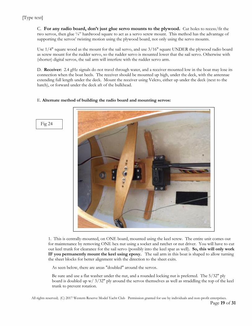
two servos, then glue ¼” hardwood square to act as a servo screw mount. This method has the advantage of supporting the servos’ twisting motion using the plywood board, not only using the servo mounts. Use 1/4" square wood as the mount for the sail servo, and use 3/16" square UNDER the plywood radio board as screw mount for the rudder servo, so the rudder servo is mounted lower that the sail servo. Otherwise with (shorter) digital servos, the sail arm will interfere with the rudder servo arm. D. Receiver: 2.4 gHz signals do not travel through water, and a receiver mounted low in the boat may lose its connection when the boat heels. The receiver should be mounted up high, under the deck, with the antennae extending full length under the deck. Mount the receiver using Velcro, either up under the deck (next to the hatch), or forward under the deck aft of the bulkhead. E. Alternate method of building the radio board and mounting servos:
1. This is centrally-mounted, on ONE board, mounted using the keel screw. The entire unit comes out for maintenance by removing ONE hex nut using a socket and ratchet or nut driver. You will have to cut out keel trunk for clearance for the sail servo (possibly into the keel spar as well). So, this will only work IF you permanently mount the keel using epoxy. The sail arm in this boat is shaped to allow turning the sheet blocks for better alignment with the direction to the sheet exits.
As seen below, there are areas "doubled" around the servos.
Be sure and use a flat washer under the nut, and a rounded locking nut is preferred. The 5/32" ply board is doubled up w/ 3/32" ply around the servos themselves as well as straddling the top of the keel trunk to prevent rotation.
Fig 24
[Type text]
All rights reserved; (C) 2017 Western Reserve Model Yacht Club Permission granted for use by individuals and non-profit enterprises.
Page 20 of 31
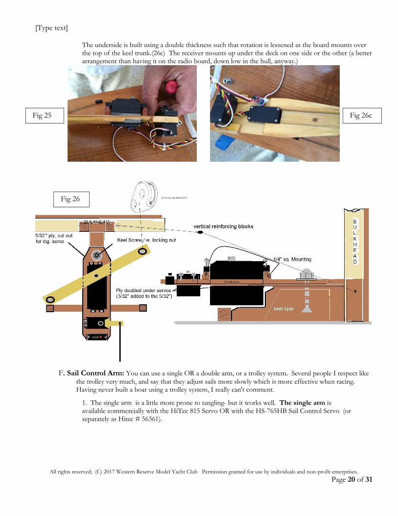
The underside is built using a double thickness such that rotation is lessened as the board mounts over the top of the keel trunk.(26c) The receiver mounts up under the deck on one side or the other (a better arrangement than having it on the radio board, down low in the hull, anyway.)
F. Sail Control Arm: You can use a single OR a double arm, or a trolley system. Several people I respect like
the trolley very much, and say that they adjust sails more slowly which is more effective when racing. Having never built a boat using a trolley system, I really can't comment.
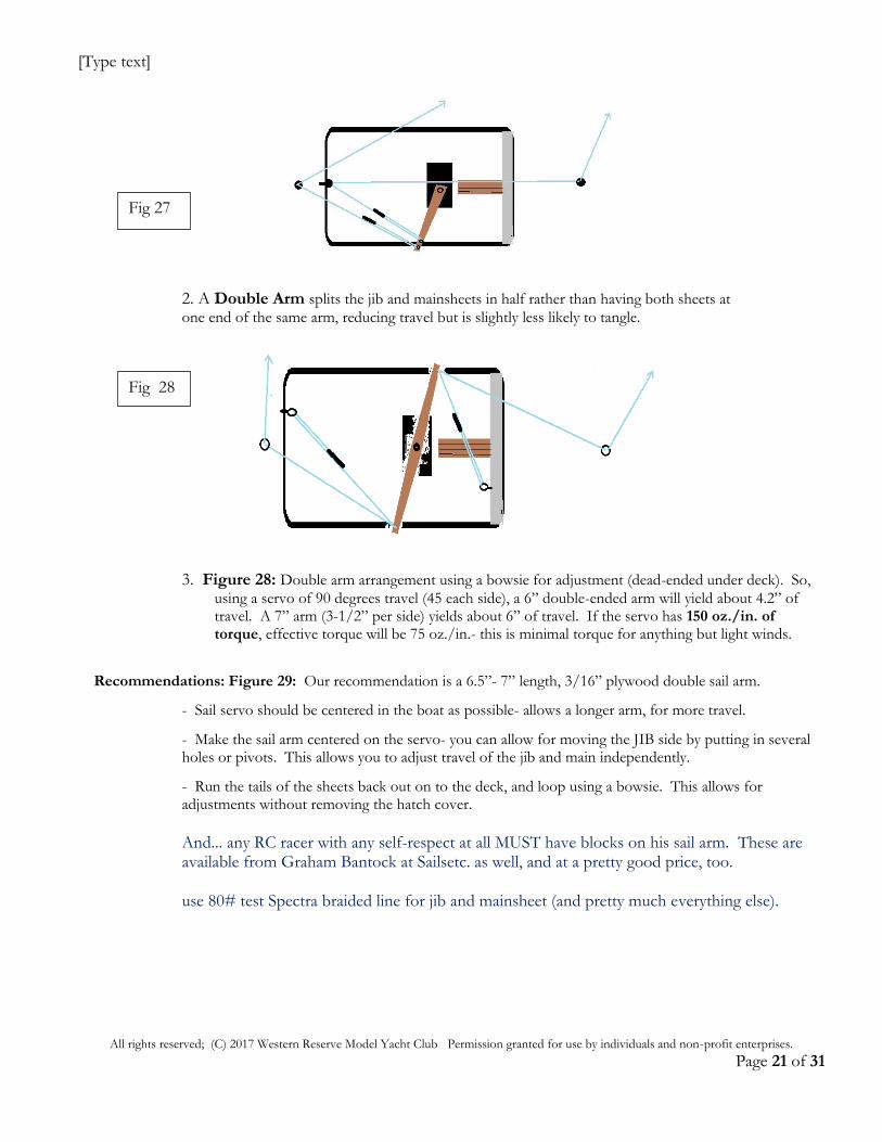
1. The single arm is a little more prone to tangling- but it works well. The single arm is available commercially with the HiTec 815 Servo OR with the HS-765HB Sail Control Servo (or separately as Hitec # 56361).
Fig 26
Fig 25 Fig 26c
[Type text]
All rights reserved; (C) 2017 Western Reserve Model Yacht Club Permission granted for use by individuals and non-profit enterprises.
Page 21 of 31
2. A Double Arm splits the jib and mainsheets in half rather than having both sheets at
one end of the same arm, reducing travel but is slightly less likely to tangle.
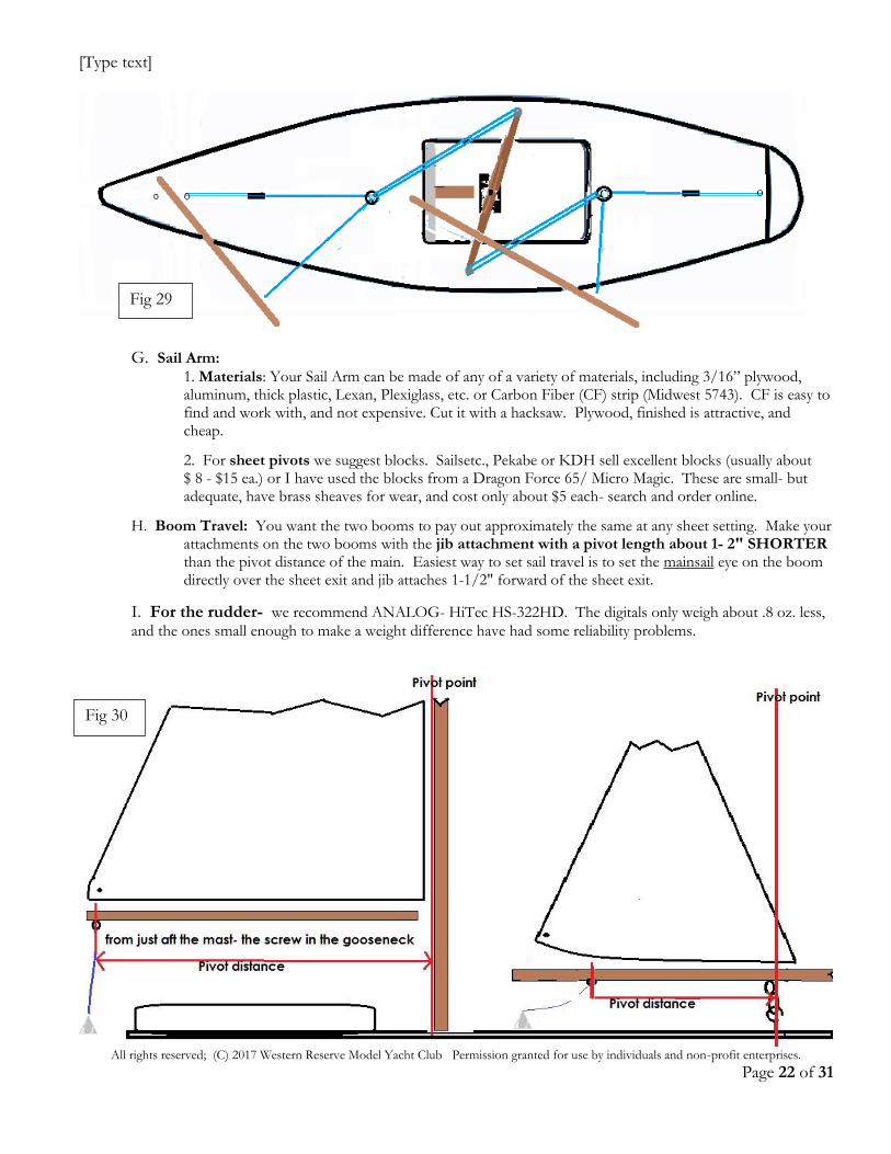
3. Figure 28: Double arm arrangement using a bowsie for adjustment (dead-ended under deck). So,
using a servo of 90 degrees travel (45 each side), a 6” double-ended arm will yield about 4.2” of travel. A 7” arm (3-1/2” per side) yields about 6” of travel. If the servo has 150 oz./in. of torque, effective torque will be 75 oz./in.- this is minimal torque for anything but light winds.
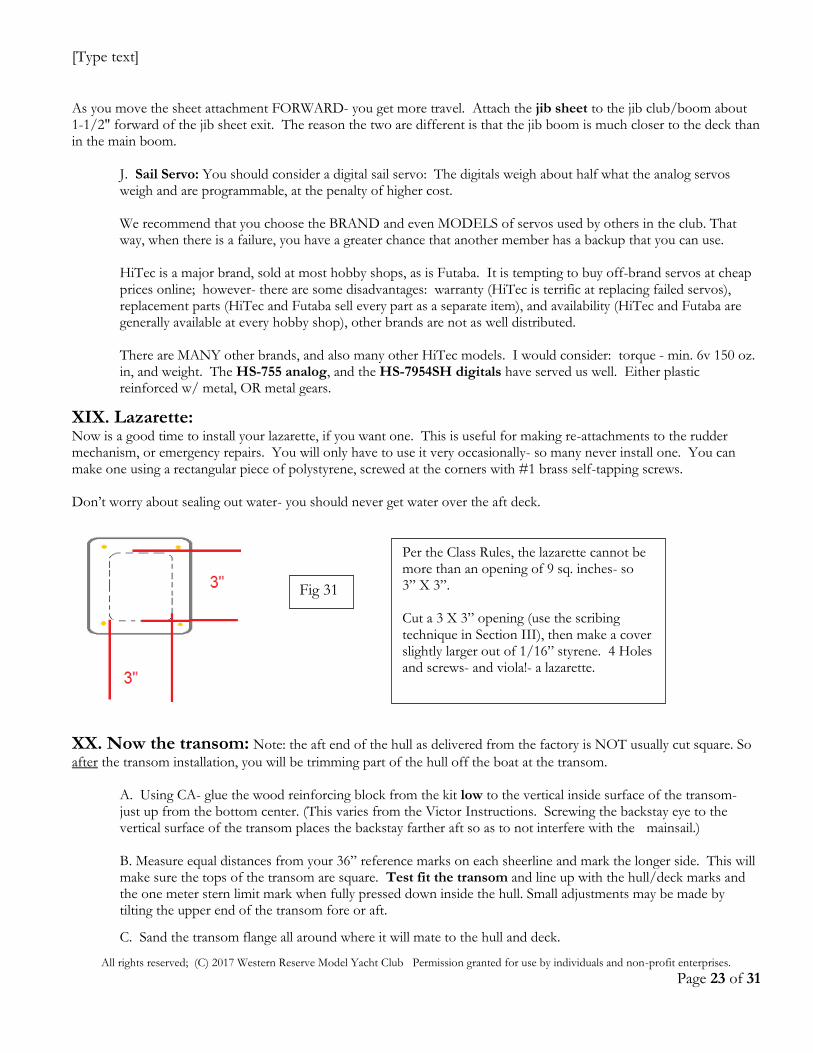
Recommendations: Figure 29: Our recommendation is a 6.5”- 7” length, 3/16” plywood double sail arm.
- Sail servo should be centered in the boat as possible- allows a longer arm, for more travel.
- Make the sail arm centered on the servo- you can allow for moving the JIB side by putting in several holes or pivots. This allows you to adjust travel of the jib and main independently.
- Run the tails of the sheets back out on to the deck, and loop using a bowsie. This allows for adjustments without removing the hatch cover.
And... any RC racer with any self-respect at all MUST have blocks on his sail arm. These are available from Graham Bantock at Sailsetc. as well, and at a pretty good price, too. use 80# test Spectra braided line for jib and mainsheet (and pretty much everything else).
Fig 27
Fig 28
[Type text]
All rights reserved; (C) 2017 Western Reserve Model Yacht Club Permission granted for use by individuals and non-profit enterprises.
Page 22 of 31
G. Sail Arm:
1. Materials: Your Sail Arm can be made of any of a variety of materials, including 3/16” plywood, aluminum, thick plastic, Lexan, Plexiglass, etc. or Carbon Fiber (CF) strip (Midwest 5743). CF is easy to find and work with, and not expensive. Cut it with a hacksaw. Plywood, finished is attractive, and cheap.
2. For sheet pivots we suggest blocks. Sailsetc., Pekabe or KDH sell excellent blocks (usually about $ 8 - $15 ea.) or I have used the blocks from a Dragon Force 65/ Micro Magic. These are small- but adequate, have brass sheaves for wear, and cost only about $5 each- search and order online.
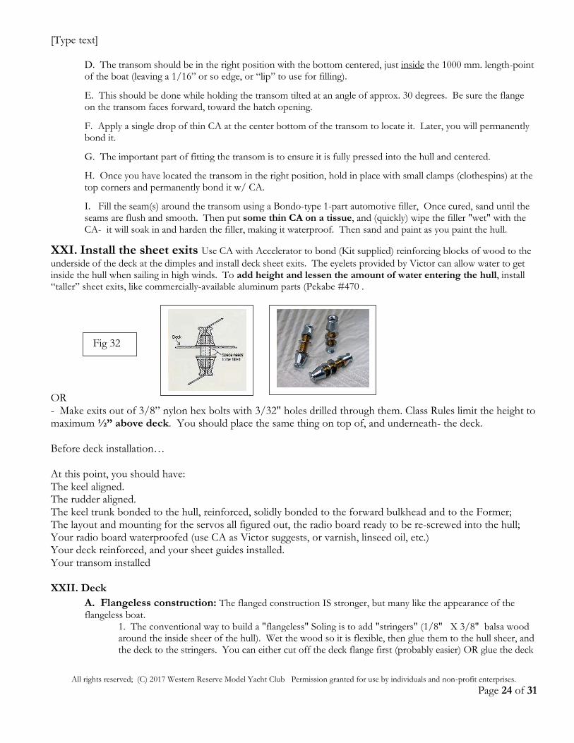
H. Boom Travel: You want the two booms to pay out approximately the same at any sheet setting. Make your attachments on the two booms with the jib attachment with a pivot length about 1- 2" SHORTER than the pivot distance of the main. Easiest way to set sail travel is to set the mainsail eye on the boom directly over the sheet exit and jib attaches 1-1/2" forward of the sheet exit.
I. For the rudder- we recommend ANALOG- HiTec HS-322HD. The digitals only weigh about .8 oz. less,
and the ones small enough to make a weight difference have had some reliability problems.
Fig 29
Fig 30
[Type text]
All rights reserved; (C) 2017 Western Reserve Model Yacht Club Permission granted for use by individuals and non-profit enterprises.
Page 23 of 31
As you move the sheet attachment FORWARD- you get more travel. Attach the jib sheet to the jib club/boom about 1-1/2" forward of the jib sheet exit. The reason the two are different is that the jib boom is much closer to the deck than in the main boom.
J. Sail Servo: You should consider a digital sail servo: The digitals weigh about half what the analog servos weigh and are programmable, at the penalty of higher cost.
We recommend that you choose the BRAND and even MODELS of servos used by others in the club. That way, when there is a failure, you have a greater chance that another member has a backup that you can use. HiTec is a major brand, sold at most hobby shops, as is Futaba. It is tempting to buy off-brand servos at cheap prices online; however- there are some disadvantages: warranty (HiTec is terrific at replacing failed servos), replacement parts (HiTec and Futaba sell every part as a separate item), and availability (HiTec and Futaba are generally available at every hobby shop), other brands are not as well distributed. There are MANY other brands, and also many other HiTec models. I would consider: torque - min. 6v 150 oz. in, and weight. The HS-755 analog, and the HS-7954SH digitals have served us well. Either plastic reinforced w/ metal, OR metal gears.
XIX. Lazarette: Now is a good time to install your lazarette, if you want one. This is useful for making re-attachments to the rudder mechanism, or emergency repairs. You will only have to use it very occasionally- so many never install one. You can make one using a rectangular piece of polystyrene, screwed at the corners with #1 brass self-tapping screws. Don’t worry about sealing out water- you should never get water over the aft deck.
XX. Now the transom: Note: the aft end of the hull as delivered from the factory is NOT usually cut square. So
after the transom installation, you will be trimming part of the hull off the boat at the transom. A. Using CA- glue the wood reinforcing block from the kit low to the vertical inside surface of the transom- just up from the bottom center. (This varies from the Victor Instructions. Screwing the backstay eye to the vertical surface of the transom places the backstay farther aft so as to not interfere with the mainsail.) B. Measure equal distances from your 36” reference marks on each sheerline and mark the longer side. This will make sure the tops of the transom are square. Test fit the transom and line up with the hull/deck marks and the one meter stern limit mark when fully pressed down inside the hull. Small adjustments may be made by tilting the upper end of the transom fore or aft.
C. Sand the transom flange all around where it will mate to the hull and deck.
Per the Class Rules, the lazarette cannot be more than an opening of 9 sq. inches- so 3” X 3”. Cut a 3 X 3” opening (use the scribing technique in Section III), then make a cover slightly larger out of 1/16” styrene. 4 Holes and screws- and viola!- a lazarette.
Fig 31
[Type text]
All rights reserved; (C) 2017 Western Reserve Model Yacht Club Permission granted for use by individuals and non-profit enterprises.
Page 24 of 31
D. The transom should be in the right position with the bottom centered, just inside the 1000 mm. length-point of the boat (leaving a 1/16” or so edge, or “lip” to use for filling).
E. This should be done while holding the transom tilted at an angle of approx. 30 degrees. Be sure the flange on the transom faces forward, toward the hatch opening.
F. Apply a single drop of thin CA at the center bottom of the transom to locate it. Later, you will permanently bond it.
G. The important part of fitting the transom is to ensure it is fully pressed into the hull and centered.
H. Once you have located the transom in the right position, hold in place with small clamps (clothespins) at the top corners and permanently bond it w/ CA.
I. Fill the seam(s) around the transom using a Bondo-type 1-part automotive filler, Once cured, sand until the seams are flush and smooth. Then put some thin CA on a tissue, and (quickly) wipe the filler "wet" with the CA- it will soak in and harden the filler, making it waterproof. Then sand and paint as you paint the hull.
XXI. Install the sheet exits Use CA with Accelerator to bond (Kit supplied) reinforcing blocks of wood to the
underside of the deck at the dimples and install deck sheet exits. The eyelets provided by Victor can allow water to get inside the hull when sailing in high winds. To add height and lessen the amount of water entering the hull, install “taller” sheet exits, like commercially-available aluminum parts (Pekabe #470 .
OR - Make exits out of 3/8” nylon hex bolts with 3/32" holes drilled through them. Class Rules limit the height to maximum ½” above deck. You should place the same thing on top of, and underneath- the deck. Before deck installation…
At this point, you should have: The keel aligned. The rudder aligned. The keel trunk bonded to the hull, reinforced, solidly bonded to the forward bulkhead and to the Former; The layout and mounting for the servos all figured out, the radio board ready to be re-screwed into the hull; Your radio board waterproofed (use CA as Victor suggests, or varnish, linseed oil, etc.) Your deck reinforced, and your sheet guides installed. Your transom installed XXII. Deck
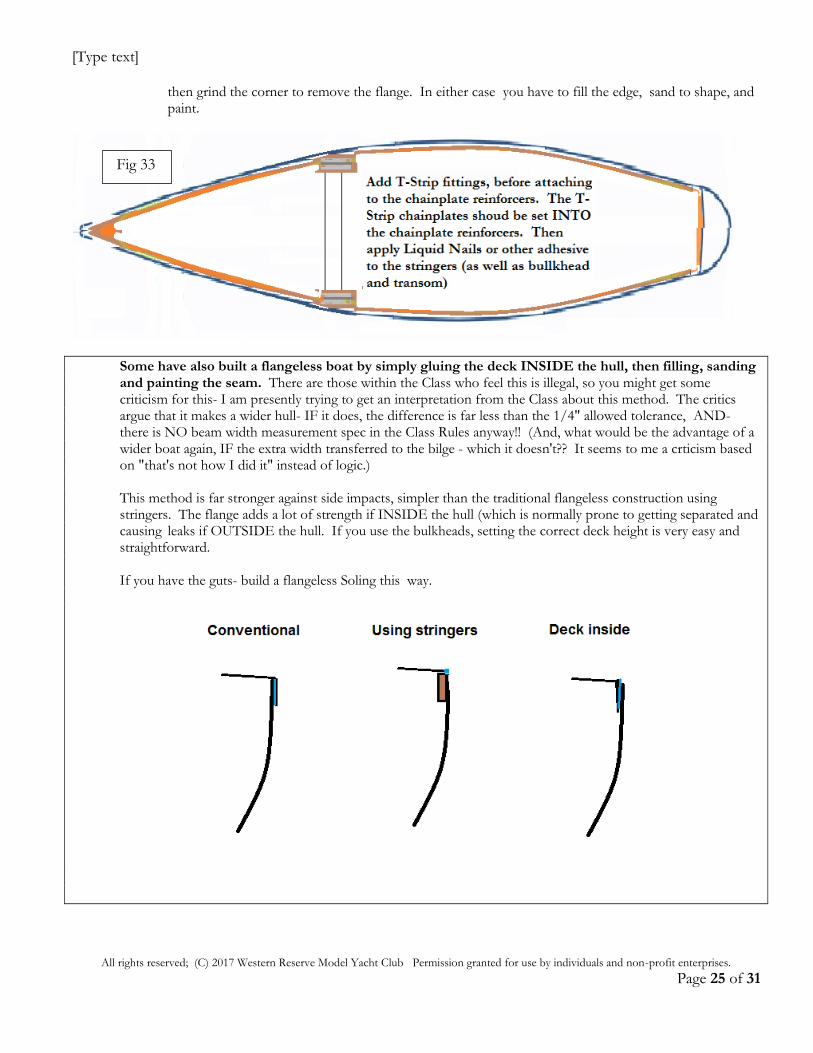
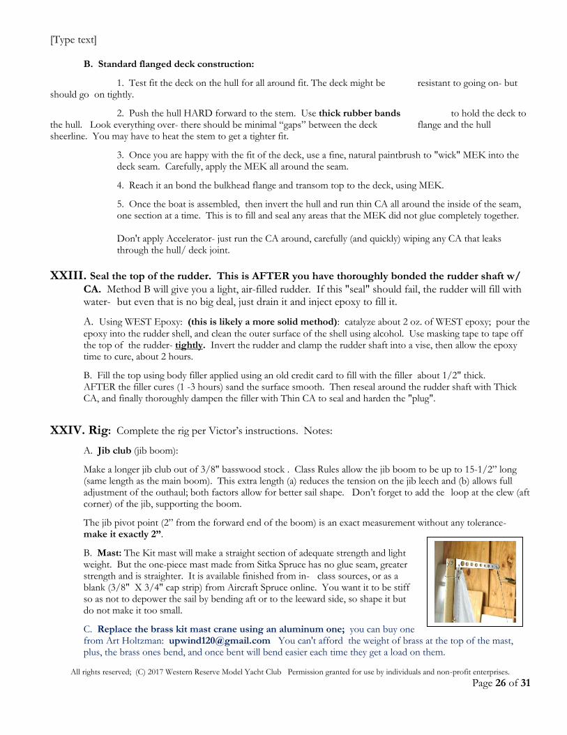
A. Flangeless construction: The flanged construction IS stronger, but many like the appearance of the flangeless boat. 1. The conventional way to build a "flangeless" Soling is to add "stringers" (1/8" X 3/8" balsa wood around the inside sheer of the hull). Wet the wood so it is flexible, then glue them to the hull sheer, and the deck to the stringers. You can either cut off the deck flange first (probably easier) OR glue the deck
Fig 32
[Type text]
All rights reserved; (C) 2017 Western Reserve Model Yacht Club Permission granted for use by individuals and non-profit enterprises.
Page 25 of 31
then grind the corner to remove the flange. In either case you have to fill the edge, sand to shape, and paint.
Some have also built a flangeless boat by simply gluing the deck INSIDE the hull, then filling, sanding and painting the seam. There are those within the Class who feel this is illegal, so you might get some criticism for this- I am presently trying to get an interpretation from the Class about this method. The critics argue that it makes a wider hull- IF it does, the difference is far less than the 1/4" allowed tolerance, AND- there is NO beam width measurement spec in the Class Rules anyway!! (And, what would be the advantage of a wider boat again, IF the extra width transferred to the bilge - which it doesn't?? It seems to me a crticism based on "that's not how I did it" instead of logic.) This method is far stronger against side impacts, simpler than the traditional flangeless construction using stringers. The flange adds a lot of strength if INSIDE the hull (which is normally prone to getting separated and causing leaks if OUTSIDE the hull. If you use the bulkheads, setting the correct deck height is very easy and straightforward. If you have the guts- build a flangeless Soling this way.
Fig 33
[Type text]
All rights reserved; (C) 2017 Western Reserve Model Yacht Club Permission granted for use by individuals and non-profit enterprises.
Page 26 of 31
B. Standard flanged deck construction:
1. Test fit the deck on the hull for all around fit. The deck might be resistant to going on- but should go on tightly.
2. Push the hull HARD forward to the stem. Use thick rubber bands to hold the deck to the hull. Look everything over- there should be minimal “gaps” between the deck flange and the hull sheerline. You may have to heat the stem to get a tighter fit.
3. Once you are happy with the fit of the deck, use a fine, natural paintbrush to "wick" MEK into the deck seam. Carefully, apply the MEK all around the seam.
4. Reach it an bond the bulkhead flange and transom top to the deck, using MEK.
5. Once the boat is assembled, then invert the hull and run thin CA all around the inside of the seam, one section at a time. This is to fill and seal any areas that the MEK did not glue completely together. Don't apply Accelerator- just run the CA around, carefully (and quickly) wiping any CA that leaks through the hull/ deck joint.
XXIII. Seal the top of the rudder. This is AFTER you have thoroughly bonded the rudder shaft w/
CA. Method B will give you a light, air-filled rudder. If this "seal" should fail, the rudder will fill with water- but even that is no big deal, just drain it and inject epoxy to fill it.
A. Using WEST Epoxy: (this is likely a more solid method): catalyze about 2 oz. of WEST epoxy; pour the
epoxy into the rudder shell, and clean the outer surface of the shell using alcohol. Use masking tape to tape off the top of the rudder- tightly. Invert the rudder and clamp the rudder shaft into a vise, then allow the epoxy time to cure, about 2 hours.
B. Fill the top using body filler applied using an old credit card to fill with the filler about 1/2" thick. AFTER the filler cures (1 -3 hours) sand the surface smooth. Then reseal around the rudder shaft with Thick CA, and finally thoroughly dampen the filler with Thin CA to seal and harden the "plug".
XXIV. Rig: Complete the rig per Victor’s instructions. Notes:
A. Jib club (jib boom):
Make a longer jib club out of 3/8" basswood stock . Class Rules allow the jib boom to be up to 15-1/2” long (same length as the main boom). This extra length (a) reduces the tension on the jib leech and (b) allows full adjustment of the outhaul; both factors allow for better sail shape. Don’t forget to add the loop at the clew (aft corner) of the jib, supporting the boom.
The jib pivot point (2” from the forward end of the boom) is an exact measurement without any tolerance- make it exactly 2”.
B. Mast: The Kit mast will make a straight section of adequate strength and light weight. But the one-piece mast made from Sitka Spruce has no glue seam, greater strength and is straighter. It is available finished from in- class sources, or as a blank (3/8" X 3/4" cap strip) from Aircraft Spruce online. You want it to be stiff so as not to depower the sail by bending aft or to the leeward side, so shape it but do not make it too small.
C. Replace the brass kit mast crane using an aluminum one; you can buy one from Art Holtzman: [email protected] You can't afford the weight of brass at the top of the mast, plus, the brass ones bend, and once bent will bend easier each time they get a load on them.
[Type text]
All rights reserved; (C) 2017 Western Reserve Model Yacht Club Permission granted for use by individuals and non-profit enterprises.
Page 27 of 31
D. Or…make an aluminum mast crane using 1/16” thick T6- 6061 aluminum, .061 X 4" long. E. Upgrade the standard sheets using 50# Braided Dacron, 60# test or 80# braided "Spectra" fishing line for more durability and abrasion resistance. The larger diameter is more for use in bowsies than for strength.
F. Be sure to wrap strong fishing line around the base of the mast, and around the forward end of the mainsail boom, to avoid splitting the wood. Seal it with thin CA.
G. Rigging adjustments needed for racing
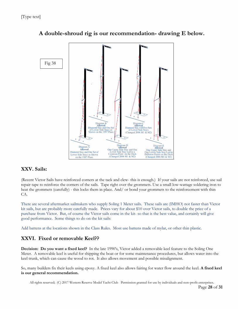
1. Shroud adjusters- Install 4 adjusters (double shroud rig) to allow precise straightening and positioning of the mast. You will need 4 - 2 each for the shrouds (lower stays), and 2 for the "uppers" (stays that replace the diamonds in the standard Victor setup) .
a. You can use Sailsetc., or Pekabe, KDH rigging screws.
b. These attach to the wire, then hook to the chainplate fittings. The Sailsetc. ones are on their website; Pekabe or KDH ones are available online as well.
2. Aluminum Spreaders- you can't afford the extra weight of brass up the mast K&S streamlined aluminum tubing is "racy"!!
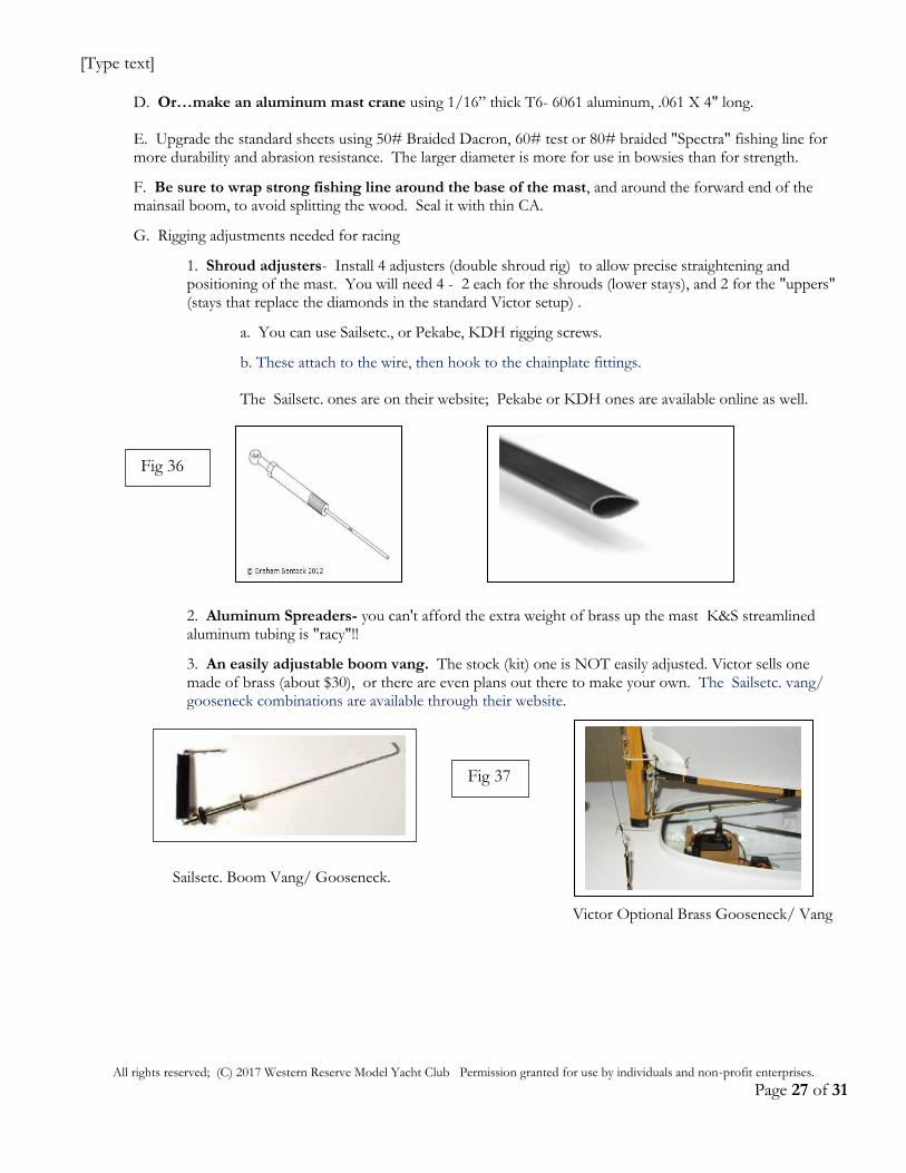
3. An easily adjustable boom vang. The stock (kit) one is NOT easily adjusted. Victor sells one made of brass (about $30), or there are even plans out there to make your own. The Sailsetc. vang/ gooseneck combinations are available through their website.
Sailsetc. Boom Vang/ Gooseneck. Victor Optional Brass Gooseneck/ Vang
Fig 36
Fig 37
[Type text]
All rights reserved; (C) 2017 Western Reserve Model Yacht Club Permission granted for use by individuals and non-profit enterprises.
Page 28 of 31
A double-shroud rig is our recommendation- drawing E below.
XXV. Sails: (Recent Victor Sails have reinforced corners at the tack and clew- this is enough.) If your sails are not reinforced, use sail repair tape to reinforce the corners of the sails. Tape right over the grommets. Use a small low-wattage soldering iron to heat the grommets (carefully) - this locks them in place. And/ or bond your grommets to the reinforcement with thin CA. There are several aftermarket sailmakers who supply Soling 1 Meter sails. These sails are (IMHO) not faster than Victor kit sails, but are probably more carefully made. Prices vary for about $10 over Victor sails, to double the price of a purchase from Victor. But, of course the Victor sails come in the kit- so that is the best value, and certainly will give good performance. Some things to do on the kit sails: Add battens at the locations shown in the Class Rules. Most use battens made of mylar, or other thin plastic.
XXVI. Fixed or removable Keel?? Decision: Do you want a fixed keel? In the late 1990’s, Victor added a removable keel feature to the Soling One Meter. A removable keel is useful for shipping the boat or for some maintenance procedures, but allows water into the keel trunk, which can cause the wood to rot. It also allows movement and possible misalignment. So, many builders fix their keels using epoxy. A fixed keel also allows fairing for water flow around the keel. A fixed keel is our general recommendation.
Fig 38
[Type text]
All rights reserved; (C) 2017 Western Reserve Model Yacht Club Permission granted for use by individuals and non-profit enterprises.
Page 29 of 31
XXVII. Fill the Keel (after all finishing, rigging, etc.)- you can fill the keel, ideally to 7 lbs. The heavier the keel,
the better the boat will go upwind. It is probably better to have a 10# 4oz. boat with a 7 lb. keel than a 10.0 lb. boat with a 6# 12 oz. keel. Some builders go further than that- even to 8 lbs. in the keel, and take as much as possible out of the hull and rig, again sometimes having a boat that is as much as 4 oz. heavier than minimum.
A. If you don’t have access to a digital scale or the ability to precisely weigh your boat- assume the finished hull with all the rig and electronics components (incl. battery pack) weighs 3.5 lbs. and you build to 10.0 lbs. minimum weight. You would need a 6.75 lb./ 108 oz. keel. If you come out a few ounces overweight- that is OK- better than having a too-light keel. B. Weighing: put all on the boat- including batteries, install servos, the rig, including the sails. Don’t weigh the keel shell or place it on the scale/ or in the boat- you’ll weigh it separately as you pour your keel. If you like, you can also fill the keel so that you can bring the boat to a perfect weight of just over 10 lbs. A pound is 16 oz. (and don’t confuse WEIGHT ounces with fluid ounces). Weighing your almost- complete boat, then subtracting your boat weight from 10.0 lbs/ 160 oz., can determine desired total keel weight. A 3 lb. boat (leaving 7 lbs. for the keel and a total boat weight of 10 lbs.) would weigh just 48 oz., incl. batteries, electronics, servos, sails, etc. A hard to reach goal.
Weight assumptions: An empty, unpainted keel shell, with keel spar, screw, and wing nut: 4.75 oz. An 8 oz. cup of lead shot weighs approximately 50 oz. An 8 oz. cup of epoxy weighs approximately 9 oz.
C. Filling the keel:
To get a 7 lb. keel: You will need to add about 1.75 cups (weighs 87.5 oz.) of lead, and 1.75 cups epoxy (15.75 oz.), for a total keel weight of 109 oz. including shell and spar. Filling the keel to the top, and painting will add the extra 3 oz. to get near 110 oz.
1. You will have about 20 minutes before the epoxy or polyester “kicks”- and will generate a lot of heat. So, mix the epoxy only after all is set up.
2. Use 8 oz. paper cups, and TWO small funnels- I have a set of nylon funnels with a small 3” one and a 5” one. I use the small one for lead, and the larger one to pour the epoxy- one on each side of the keel spar.
3. Double-check to see that the keel shell halves are solidly bonded together, and taped. Also mask the upper part of the keel to lessen the chance of dripping epoxy on the shell.
4. The tricky part here is to be sure that the epoxy is thoroughly mixed in with the lead.
- Pour about 1/4 of the cup full of epoxy into the keel. - Pour in about 1/3 of the lead shot. - Add another ¼ of the cup of epoxy. - Using a long flat-bladed screwdriver, carefully mix the lead shot and epoxy as it is inside the keel. Careful!- Don't punch the screwdriver through the bottom of the keel!!!
Repeat this procedure- alternating epoxy then lead, and mixing. Weigh the keel after the first cup of lead is in the keel- you should be at about 4.5 lbs. at that point.
5. Once all the lead and epoxy is in the keel lead - Wipe the keel off first using alcohol, then go balance it on the scale. (You should be about at your target weight, or maybe a little under.)
6. If your keel is under weight, add shot to bring it up to about 1 ounce by weight lighter than
your target. The excess epoxy will overflow as the lead is added.
[Type text]
All rights reserved; (C) 2017 Western Reserve Model Yacht Club Permission granted for use by individuals and non-profit enterprises.
Page 30 of 31
7. If your keel is “heavy”- tilt the keel over your epoxy container, and use the screwdriver to “pull” some lead out of the keel. Weigh after each small amount of lead is removed. You won’t have to remove much to make a big difference. The lead will sink to the bottom, and you can refill the keel shell using the lighter epoxy.
8. Weigh the keel again and adjust the lead until you are about 5 oz. under target weight, allowing for topping off w/ epoxy, and final painting.
9. Fill the keel up with epoxy to within 1/4” or so of the top. After the keel is filled- wipe it off using paper towels and alcohol.
10. Within 20 minutes- prop the keel up in a tub or bucket of water, just in case you get some heat buildup. You can also support the keel on the water after your first lead is added; (it floats up to that point!), and pour epoxy while the keel is in the water. Allow the keel to cure for 24 hours before topping off with epoxy.
XXVIII. Sealing a removable keel - if you want a removable keel. Even after following the
recommendations below, you will still need to remove it periodically (every 3 months?) and allow everything to dry out. MANY methods have been used to seal a removable keel from water intrusion. A. Pack the keel box through the hull opening with Vaseline. Coat the keel spar also with Vaseline, then slide it into the keel trunk, and tighten the keel bolt wing nut. Wipe off the excess. You will have to do this each year. B. Coat the keel spar with plumber’s putty. It will seal, and will be (with some difficulty) removable.
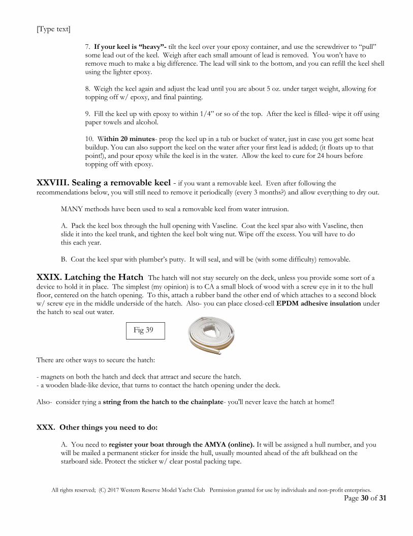
XXIX. Latching the Hatch The hatch will not stay securely on the deck, unless you provide some sort of a
device to hold it in place. The simplest (my opinion) is to CA a small block of wood with a screw eye in it to the hull floor, centered on the hatch opening. To this, attach a rubber band the other end of which attaches to a second block w/ screw eye in the middle underside of the hatch. Also- you can place closed-cell EPDM adhesive insulation under the hatch to seal out water.
There are other ways to secure the hatch: - magnets on both the hatch and deck that attract and secure the hatch. - a wooden blade-like device, that turns to contact the hatch opening under the deck. Also- consider tying a string from the hatch to the chainplate- you'll never leave the hatch at home!!
XXX. Other things you need to do: A. You need to register your boat through the AMYA (online). It will be assigned a hull number, and you will be mailed a permanent sticker for inside the hull, usually mounted ahead of the aft bulkhead on the starboard side. Protect the sticker w/ clear postal packing tape.
Fig 39
[Type text]
All rights reserved; (C) 2017 Western Reserve Model Yacht Club Permission granted for use by individuals and non-profit enterprises.
Page 31 of 31
B. Mark your sails with your hull number: you can buy vinyl numbers at the hardware store, or online through AMYA (Ship’s Store”) –3” high and 3/8” thick (stroke), and located just below the Soling “omega” logo. The starboard markings go above the port side markings. C. Indelible Marker: However, sometimes the vinyl shrinks, causing distortion of the sail cloth: so many sailors use Sharpie marker to make their sail numbers. - use MicroSoft Word Arial Narrow 300 font; - Print out your sail numbers black on printer paper- verify that they are 3" high X 3/8" thick. - Tape the printing paper to a table, then; - lay the sails over the template, tape the sails in place to the table. - outline the numbers in black, BALLPOINT pen. The ballpoint creases the arond the outline of the sail number, and will lessen the "bleeding" of the marker. - Fill in the numbers using with industrial size (large tip) Sharpie marker. D. If you want to color your sails- use the aerosol fabric paint designed for florists’ silk flowers called Design Master. (Michael's, Pat Catan's, or Hobby Lobby. Just mask and spray. This will make your boat easier to identify on the water. Identifying which boat is yours, and which way you are headed, is a problem when the boat is 50 yards or so away from you. Have Fun!!! See also “Finishing Your Soling”, and “Electronics and Batteries”. Questions or comments? Mike Wyatt [email protected] Western Reserve Model Yacht Club 440-259-8037 or 440-478-8208
This document formatted in Garamond This typeface uses 10% less ink and less
paper than any other when printing.