Wes Ballantyne Masters of Architecture Portfolio
28
Wes Ballantyne 2012 M. arch. Graduate
-
Upload
wes-ballantyne -
Category
Documents
-
view
236 -
download
0
description
Compilation of my architecture work and more from the School of Architecture at MSU Bozeman.
Transcript of Wes Ballantyne Masters of Architecture Portfolio

Wes Ballantyne2012 M. arch. Graduate
NAME: Wesley Aatami BallantyneADDRESS: 1280 Albion St. # 37 Denver, CO 80220PHONE: 406.459.2074EMAIL: [email protected]

C O N T E N T S
BIM_BUILDING CONSTRUCTION
INTERNSHIP WORKTRAVEL DRAWINGS
(SIP)6” rigid foam insulation
EPDM roo�ng
vapor barrier
7/16” OSB
7/16” OSB
{
polyole�n closed cell bedding tape (continuous) extruded aluminum sill
spacer
capillary slab with light di�using tissue
outer glass pane
inner glass pane
extruded aluminum sill
polyole�n closed cell bedding tape (continuous)
{Kapilux windowc
pressure treated SIP end cap
common nails at 6” O.C.
stainless steel �ashing
gypsum board
pressure treated curb mount
pressure treated curb mount
tamper proof screw at 18” O.C.
weep slot
extruded aluminum perimeter frame
gypsum board
curb spacer
continuous sealant
polyole�n closed cell bedding tape (continuous)
extruded aluminum sill leg
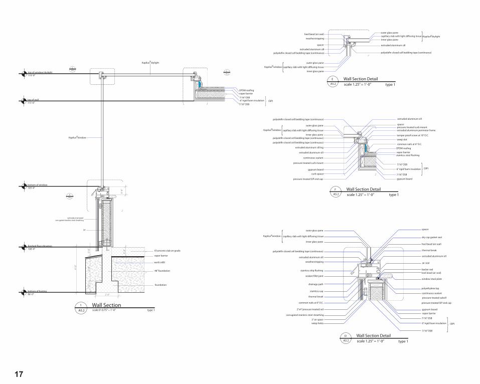
Wall Section Detailscale 1.25” = 1’-0”A5.2
F
type 1
polyole�n closed cell bedding tape (continuous)extruded aluminum sill
heel bead (air seal)
spacer
weatherstripping
capillary slab with light di�using tissue
outer glass pane
inner glass pane
capillary slab with light di�using tissueouter glass pane
inner glass pane
extruded aluminum sill
polyole�n closed cell bedding tape (continuous)
{Kapilux windowc
{
Kapilux skylightc
Wall Section Detailscale 1.25” = 1’-0”A5.2
E
type 1
A5.2
E
A5.2
F
(SIP)6” rigid foam insulation
EPDM roo�ngvapor barrier
7/16” OSB {
Kapilux window
Kapilux skylight
7/16” OSB
A5.2
D
3’-4
”1’
-0”
4’-0
”
0’-8
”
0’-6
”
2’-0”
SIP
vertically orientated corrugated stainless steel sheathing
0’-6
”
c
c
vapor barrier
earth in�ll
48” foundation
foundation
6”concrete slab on grade
Wall Sectionscale 0’-0.75” = 1’-0”A5.2
1type 1
top of window/skylight115’-0”
�nished �oor elevation100’-0”
bottom of footing96’-0”
top of wall113’-6”
bottom of window105’-0”
Wall Section Detailscale 1.25” = 1’-0”A5.2
D
type 1
Kapilux windowc {polyole�n closed cell bedding tape (continuous)
capillary slab with light di�using tissue
outer glass pane
inner glass pane
extruded aluminum sill
weatherstripping
stainless drip �ashing
sealant �llet joint
thermal break
drainage path
stainless cap
corrugated stainless steel sheathing
2”x4” pressure treated rail
common nails at 6” O.C.
2” air spaceweep holes (SIP)
{
backer rod
spacer
pressure treated SIP end cap
pressure treated subsill
6” rigid foam insulation
vapor barrier
7/16” OSB
7/16” OSB
extruded aluminum sill
gypsum board
dry cap gasket seal
heel bead (air seal)
air seal
heel bead (air seal)
window stool plate
polyethylene lap
continuous sealant
thermal break
wall section
A5.2
H2AHumanTwoArchitecture
2.4.2010
Rachel AndersonWes Ballantyne
May 4, 2010
01
09
07
19
15
UNDERGRADUATE WORK
Technical Drawings
Academic Work
GRADUATE WORK


Academic WorkGraduate Studio 2011-2012UnderGrad 2008 - 2011

Key words: Permeable, private, public, flexibil ity, collaboration, fi lter
The site for the art center is located one block north of the bustle of Main Street on Mendenhall
Street between Tracy and Black streets. The site transitions from busy downtown Bozeman to
a quiet residential area. I have decided to develop the south side of the site acknowledging this
side as the more travelled and leave the north side of the site for future housing development.
The architecture encourages levels of interaction, both public and private, through semi-perme-
able and non-permeable spaces. These are spaces where people come together or disperse.
Much like a fi lter, the perimeter of the site is designated for permeable, public programs respond-
ing to pedestrian and vehicular traffic around the site. The semi-permeable program on the pe-
rimeter will also aid in identifying and showcasing what goes on inside and the character of the
building. Semi-permeable spaces include the entrance and lobby space, gallery and library.
As the program shifts to the North side of the site and to the second level, the spaces become less
permeable and more private. Spaces designated for privacy include the theatre, on the West side
of the building, workshops on the north wall, and dance studios holding the East wall. The theatre
acts as a solid sculptural piece to the project. The theatre feels very thick and gives a sense of
privacy because of the concrete material that wraps the building. The workshops are loud and de-
mand proximity to delivery drop-offs via the alley; these spaces are thick walled with raw ma-
terials. Artist studios and administration spaces are placed on the second story where they share
views over the street. The second floor is open to the public with varying degrees of privacy. The
art studios will have flexible walls and are thought of as a whole space implying the importance of
sharing ideas and space. At night, the studios will be lit up and passersby will be able to under-
stand which studios are being used and observe the vague movements of dancers in the dance
studios. The theatre is placed on the opposite corner of the site as another performance program.
The theatre will be open to the public when the arts center is closed for concerts and other events.
Arts Center Bozeman, MT5 E mendenhall ST
01
SECTION 1 | East - West
Interior Entry and Lobby
Beam Structure
Mechanical System
Column Structure

S T U D I O 558Arts Center Bozeman, MT
02
THEATRE WALL SECTION LOBBY AND ART STUDIO WALL SECTION
FIRST FLOOR PLAN |
SECOND FLOOR PLAN ||SECTION 2 || North - South
DESIGN DEVELOPMENT || plans and sections

Studio_551
Skin Language Based On Golf Ball Trajectory and Par Designations:
Par 3_ 100 - 250 Yards (750 FT. Max)
Par 4_ 250-400 Yards (1200 FT. Max)
Par 5_ 450 - 600 Yards (1800 FT. Max.)
3
4
5
Site Plan Diagram Key
Bike Path
Tee-off Point
Course Par
Course Hole Number3
15
O p t i m i z i n g D e n s i t y This project developed after a realization that clean and obtainable water is a valuable commodity in the slums of Nairobi where many people don’t have the means to acquire clean water. One of the major water suckers in Nairobi is the golf course. Each of Nairobi’s five golf courses consume about 200,000 gallons of water a year. Not only do golf courses use a lot of water but they also take up a large portion of valuable land otherwise used for building development. The golf course is a hard program in that the land that is taken up by a golf course is only used for one ac-tivity and only serves a certain small percentage of the population in Nairobi. The Railway Golf Club was chosen as a site because of its location near the Central Business District and the industrial sector of Nairobi. To fully realize the Railway Golf Club land potentail, each golf hole was extruded from the golf club site and lined up around the central rail yard. Each golf green is the roof of low-income housing below. Up to five floors of housing will support each course. On the main level of each course will be community markets, restaurants, bars, clubs, and retail for the city. The individual living unit is designed to be flexible in that each shared wall will have a temporary wall section for future flexibility and utilization of the apartment buildings. The golf course is a central green space for the city of Nairobi including a bike path route which is intertwined within the city to promote a new green activity and travel decongestion. The golf club apart-ment building complex provides mass housing for low-income workers and students as well as a new golf club for the city of Nairobi.
Site S e c t i o n _03

Studio_551O p t i m i z i n g D e n s i t y
R o o f Plan_
T y p . Floor Plan_
Main Level Market and Retail
Residential levels 1-5
Golf Course Roof
4 0 0 SQ. Foot Apartment Layouts
3 0 0 SQ. Foot Apartment Layouts
E x p l o d e d Structural Diagram_
Apartment Shade S k i n _
Apartment Shade System
Golf Ball Screen
Skin Structure
Secondary Concrete Column Structure
Vertical Stair Cores
Main Concrete Pylon Structure
Tertiary Skin Structure
Elevator Cores
Site S e c t i o n _
N a i r o b i , Kenya
04
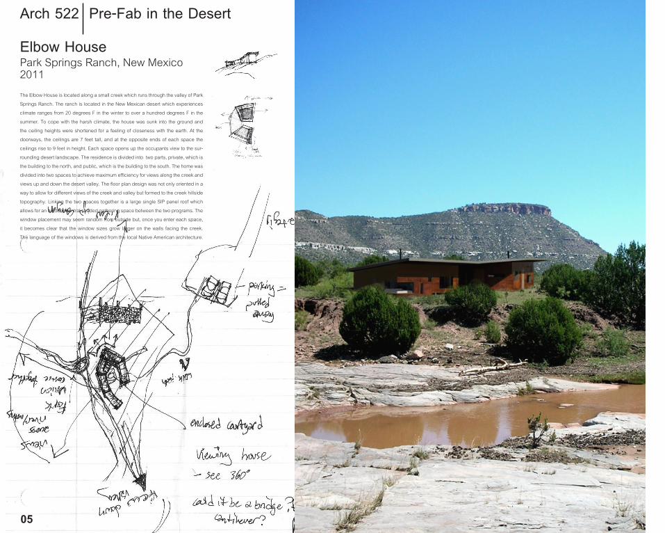
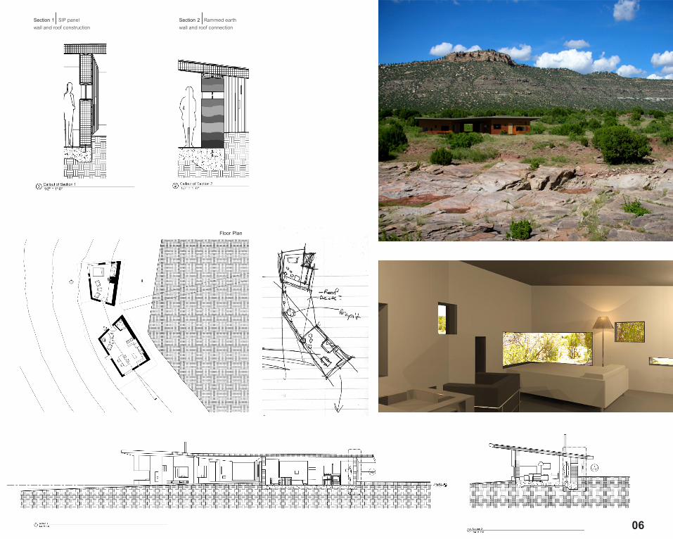
Elbow HousePark Springs Ranch, New Mexico2011The Elbow House is located along a small creek which runs through the valley of Park
Springs Ranch. The ranch is located in the New Mexican desert which experiences
climate ranges from 20 degrees F in the winter to over a hundred degrees F in the
summer. To cope with the harsh climate, the house was sunk into the ground and
the ceiling heights were shortened for a feeling of closeness with the earth. At the
doorways, the ceilings are 7 feet tall, and at the opposite ends of each space the
ceilings rise to 9 feet in height. Each space opens up the occupants view to the sur-
rounding desert landscape. The residence is divided into two parts, private, which is
the building to the north, and public, which is the building to the south. The home was
divided into two spaces to achieve maximum efficiency for views along the creek and
views up and down the desert valley. The floor plan design was not only oriented in a
way to allow for different views of the creek and valley but formed to the creek hillside
topography. Linking the two spaces together is a large single SIP panel roof which
allows for an outdoor central shaded gathering space between the two programs. The
window placement may seem random from outside but, once you enter each space,
it becomes clear that the window sizes grow larger on the walls facing the creek.
The language of the windows is derived from the local Native American architecture.
Arch 522 Pre-Fab in the Desert
05
06
Floor Plan
Section 1 SIP panel wall and roof construction
Section 2 Rammed earthwall and roof connection
//Rome Summer 2010
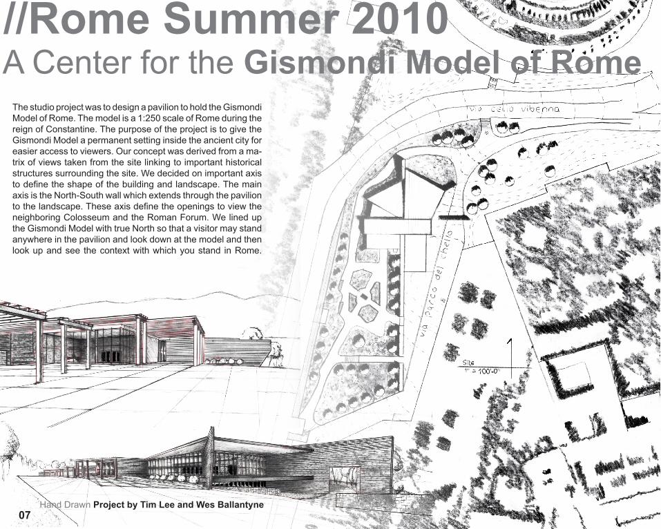
Hand Drawn Project by Tim Lee and Wes Ballantyne07
A Center for the Gismondi Model of RomeThe studio project was to design a pavilion to hold the Gismondi Model of Rome. The model is a 1:250 scale of Rome during the reign of Constantine. The purpose of the project is to give the Gismondi Model a permanent setting inside the ancient city for easier access to viewers. Our concept was derived from a ma-trix of views taken from the site linking to important historical structures surrounding the site. We decided on important axis to define the shape of the building and landscape. The main axis is the North-South wall which extends through the pavilion to the landscape. These axis define the openings to view the neighboring Colosseum and the Roman Forum. We lined up the Gismondi Model with true North so that a visitor may stand anywhere in the pavilion and look down at the model and then look up and see the context with which you stand in Rome.

//Rome Summer 2010A Center for the Gismondi Model of Rome
08
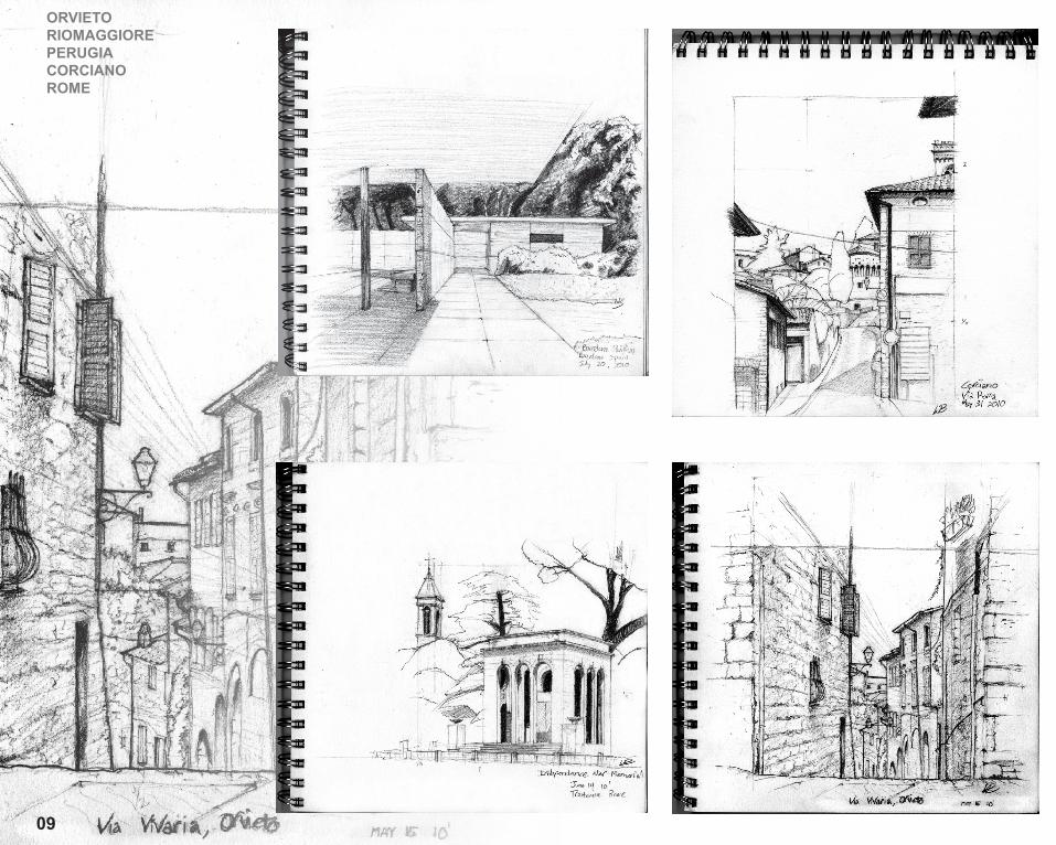
ORVIETORIOMAGGIOREPERUGIACORCIANOROME
09

SIENALUCCABARCELONACOMO
10

11
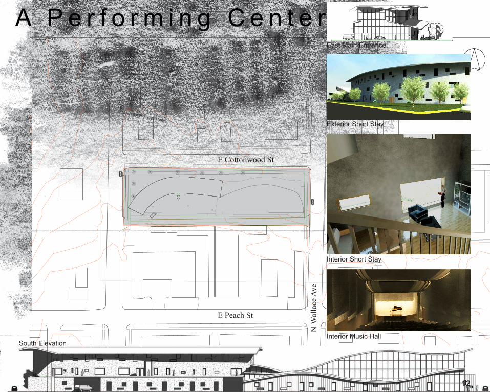
YR 4The design began with a program decision of a music hall and short stay apartments. The restricted site is located on Wallace and Cottonwood street in the industrial area of Bozeman, MT. In music there is a form of musical progression called counterpoint where one or several notes are played against each other. These notes sound differ-ent and move independantly from each other but when they are played together they produce a harmony. The composer Bach was famous for this type of progression. After dissecting a section of Bach’s score from Fugue no. 17, I developed several Parti’s. The Parti’s, view opportunities, and site restrictions led to the final footprint of the building. The concept of musical notes shows through in the skin and window placement in the two buildings. The wall of the performing hall is cladded of wood much like an orchestral instrument. The short stay apartments are offset in sec-tion to allow great views of the bridger mountains and surrounding bozeman area.
Bo
zem
an
, M
T
1 Roof Plan
12
East Main Entrance
Interior Short Stay
Interior Music Hall
Exterior Short Stay
E Peach StN
Wal
lace
Ave
E Cottonwood St
A P e r f o r m i n g C e n t e r
South Elevation

1713
Exterior Night Rendering
South Entrance View East View West View
Butte has a rich history which began with one of the largest copper mines in the world and because of its history; Butte has a very unique community. Butte’s community has had to adapt to each change throughout the past. The current city of Butte only exists because of the community’s ability to exchange goods and services within the different cultures that reside in Butte. This design focuses on the identity of Butte in the past and the current identity of Butte. The key word of this project is adaptation. Butte has adapted from its rich mining past to almost becoming a ghost town, and now to a current period of growth. Butte has shifted from its dependence on mining to small businesses and arts. People are moving into historical uptown Butte and Butte is growing once again. This project will generate exchange through differences in ma-teriality and space. The building shape and placement on the site is derived from a matrix of the surrounding proof of mining around Butte such as the headframes and the Berkely Pitt. This element which is evident in every building space signifies Butte’s growth and adaptation and shows the overall idea that Butte’s future embraces its past.
A Growing PlaceBUTTE, MT

18West View 14East Section South Market Place Section Community Center Section
Main Floor Plan 2nd Floor Plan of Community Center Roof Plan
Community Center
Market Place
OfficesParking
Metal and GlassStructure
A Growing PlaceBUTTE, MT

EXITMontana State UniversityBIM Model
2
2
2
2
3 3
3 3
3
3
3
2A3.1
1A 3.1
70' - 8"
47' - 9"
1 2 3
A
B
C
D
E
30' -
6"
25' -
8"
4' -
0"
2' - 0"
14' - 10" 1' - 0"
1' -
9"
6' -
4"
6' -
5"
10' - 3"
25' - 5 1/2"
4
36' - 6 1/2"
25' - 9"
1' - 8 1/2"
20' -
8"
28' - 6 3/4"
15' - 10 1/2"6' - 1"
10' -
0 1
/2"
20' -
0 1
/2" 15
' - 0
1/2
"
9' -
9 1/
2" 13' -
9 1
/2"
17' - 4 1/2"
13' - 10 1/2"
4' - 10 1/2"
4' -
0"
2' - 8 1/16"
2' -
8 1/
16"
2' -
8 1/
16"
2' - 8 1/16"
7' -
11"
1.2
A5.3 A5.1 A6.1
A5.2
A5.4
F.F.E. = 100’
1
3
STORAGE 3
OFFICE 5
GALLERY 1
GALLERY 2
STORAGE 4
MENS BATH-ROOM 6
WOMENS BATHROOM 7
1.2
1
2
3
1/4" = 1'-0"PLAN A
A1.2
1 16
1
1
H2AHumanTwoArchitecture
2.4.2010
Rachel AndersonWes Ballantyne
May 4, 2010
Building Plan
A1.2
Code Analysis
Chapter 3: use group = 3 (reference section 304.1)
Chapter 5: construction type = Type V - B (table 503)
separation = None (table 508.3.5)
Chapter 6: building element rating = None (table 601)
�re separation distance = >30’ (no rating) (table 602)
Chapter 10: occupant load = 100 sq. ft. per person : 2000 sq.ft. = 20 people = 10 male + 10 female (table 1004.1.1)
egress width = 20 x 0.2 = 4” (table 1005.1)
2 exits required (table 1015.2.1)
Chapter 29: toilet �xtures = 1 male W/C + lavatory 1 female W/C + lavatory 1 drinking fountain 1 service sink
(table 2902.1)
coversheet
symbol legend
1 wall type
A2.2
D elevation
A5.0
1 detail/enlargement
1.5 window type
1 door type
A grid line
line type legend
grid line
window type legend
1.1
1.2
1.3
1.4
1.7
1.8
1.5
1.6
2’x9’ Kapilux glass window
1’x11’ Kapilux glass window
2’x7’ Kapilux glass window
1’x9’ Kapilux glass window
1’x7’ Kapilux glass window
2’x5’ Kapilux glass window
1’x13’ Kapilux glass window
25’ x1’ Kapilux glass window
wall types
structural insulated panels (SIP) with vertical corregated steel clading
structural insulated panels (SIP) Cor-ten clading
wood frame wall with batt insulation and gypsum board
1
2
3
drawings contained
A1.0 plan series A1.1 site plan A1.2 �oor plan and life safetyA2.0 elevation series A2.1 exterior elevations (south & east) A2.2 exterior elevations (north & west)A3.0 section series A3.1 building sectionsA5.0 wall section series A5.1 type 1 wall section A5.2 type 1 wall section with Kapilux window A5.3 type 2 wall section A5.4 type 3 wall sectionA6.0 detail series A6.1 detailsB1.0 building information models B1.1 exploded details
general notes
The program contained and represented in this design is a dual purpose art gallery the “Exit Gallery” for Montana State University. Space is provided for a large main gallery suplimented by a smaller gallery speci�cally designed for UV - sensitive artwork as well as the untilitarian spaces which include o�ces, restrooms, and storage space. This program was alotted 2,000 square feet to the east of Romney Gym on Grant Street. Furthermore, the design required a compliance with the goals of the 2030 energy challenge.
A3.2
1 section cut
H2AHumanTwoArchitecture
2.4.2010
Rachel AndersonWes Ballantyne
May 4, 2010
GALLERY
Project by Rachel Anderson and Wes Ballantyne15
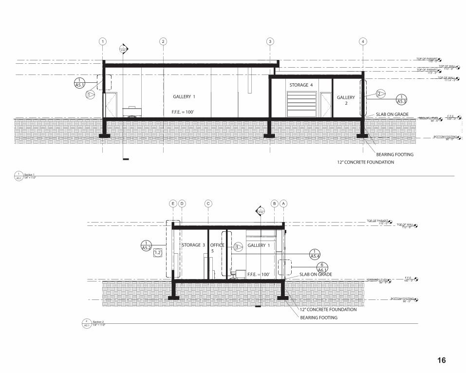
EXIT16
TOP OF WALL111.4' - 0"
1A102
1 2 3 4
TOP OF WALL113' - 6"
1/4" = 1'-0"Section 1
GALLERY 2
STORAGE 4
GALLERY 121
F.F.E. = 100’ SLAB ON GRADE
12” CONCRETE FOUNDATION
BEARING FOOTING
TOP OF PARAPIT115' - 0"
TOP OF PARAPIT113' - 0"
1
A3.1
1
A5.1 1
A5.3
1A103
ABCDE
1/4" = 1'-0"Section 2
GALLERY 1OFFICE 5
STORAGE 3 31.2
F.F.E. = 100’ SLAB ON GRADE
12” CONCRETE FOUNDATION
BEARING FOOTING
GROUND LEVEL99' - 6"
F.F.E100' - 0"
TOP OF WALL113' - 6"
TOP OF PARAPIT115' - 0"
BOTTOM FOOTING96' - 0"
2
A3.1
A5.2 1
A5.4 1
A6.16
H2AHumanTwoArchitecture
2.4.2010
Rachel AndersonWes Ballantyne
May 4, 2010
Building Sections
A3.1
GROUND LEVEL99' - 6"
F.F.E100' - 0"
BOTTOM FOOTING96' - 0"
GALLERY
17
(SIP)6” rigid foam insulation
EPDM roo�ng
vapor barrier
7/16” OSB
7/16” OSB
{
polyole�n closed cell bedding tape (continuous) extruded aluminum sill
spacer
capillary slab with light di�using tissue
outer glass pane
inner glass pane
extruded aluminum sill
polyole�n closed cell bedding tape (continuous)
{Kapilux windowc
pressure treated SIP end cap
common nails at 6” O.C.
stainless steel �ashing
gypsum board
pressure treated curb mount
pressure treated curb mount
tamper proof screw at 18” O.C.
weep slot
extruded aluminum perimeter frame
gypsum board
curb spacer
continuous sealant
polyole�n closed cell bedding tape (continuous)
extruded aluminum sill leg
Wall Section Detailscale 1.25” = 1’-0”A5.2
F
type 1
polyole�n closed cell bedding tape (continuous)extruded aluminum sill
heel bead (air seal)
spacer
weatherstripping
capillary slab with light di�using tissue
outer glass pane
inner glass pane
capillary slab with light di�using tissueouter glass pane
inner glass pane
extruded aluminum sill
polyole�n closed cell bedding tape (continuous)
{Kapilux windowc
{
Kapilux skylightc
Wall Section Detailscale 1.25” = 1’-0”A5.2
E
type 1
A5.2
E
A5.2
F
(SIP)6” rigid foam insulation
EPDM roo�ngvapor barrier
7/16” OSB {
Kapilux window
Kapilux skylight
7/16” OSB
A5.2
D
3’-4
”1’
-0”
4’-0
”
0’-8
”
0’-6
”
2’-0”
SIP
vertically orientated corrugated stainless steel sheathing
0’-6
”
c
c
vapor barrier
earth in�ll
48” foundation
foundation
6”concrete slab on grade
Wall Sectionscale 0’-0.75” = 1’-0”A5.2
1type 1
top of window/skylight115’-0”
�nished �oor elevation100’-0”
bottom of footing96’-0”
top of wall113’-6”
bottom of window105’-0”
Wall Section Detailscale 1.25” = 1’-0”A5.2
D
type 1
Kapilux windowc {polyole�n closed cell bedding tape (continuous)
capillary slab with light di�using tissue
outer glass pane
inner glass pane
extruded aluminum sill
weatherstripping
stainless drip �ashing
sealant �llet joint
thermal break
drainage path
stainless cap
corrugated stainless steel sheathing
2”x4” pressure treated rail
common nails at 6” O.C.
2” air spaceweep holes (SIP)
{
backer rod
spacer
pressure treated SIP end cap
pressure treated subsill
6” rigid foam insulation
vapor barrier
7/16” OSB
7/16” OSB
extruded aluminum sill
gypsum board
dry cap gasket seal
heel bead (air seal)
air seal
heel bead (air seal)
window stool plate
polyethylene lap
continuous sealant
thermal break
wall section
A5.2
H2AHumanTwoArchitecture
2.4.2010
Rachel AndersonWes Ballantyne
May 4, 2010
18
vertical corrugated stainless steel
vapor barrier
7/16” OSBrigid foam insulation
7/16” OSBgypsum board
2”x4” pressure treated rail
hole for electiral wires
hole for electrical wires
dual outlet electrical platescrew
electrical wiresanchor bolt
pressure treated SIP end cap
pressure treated sill platestainless steel �ashing
sill adhesive
concrete slab on grade
SIP + electrical detailn.t.s.A6.1
4
type 1
BIM details
A6.1
vertical corrugated stainless steel
vapor barrier
7/16” OSB
rigid foam insulation7/16” OSB
gypsum board
2”x4” pressure treated rail
sill plate
{SIP
capillary slab with light di�using tissueouter glass pane
inner glass pane
extruded aluminum sill
dry cap gasket seal
air seal
backer rod
thermal break
thermal break
extruded aluminum sill
extruded aluminum sill
thermal break
air sealthermal break
{Kapilux windowc
capillary slab with light di�using tissueouter glass pane
inner glass pane{Kapilux windowc
extruded aluminum sill
extruded aluminum sill
skylight curb sill
�ashing
gypsum board7/16” OSB
vapor barrierEPDM roo�ng
extruded aluminum sill
extruded aluminum sill thermal break
extension armscrew
bolt
extension bracket
sill clip
screw
sill plate
Kapilux window detailn.t.s.A6.1
1
type 3
Sliding Door detailn.t.s.A6.1
6
type 1
pressure treated SIP end cap
vertical corrugated stainless steel
2”x4” pressure treated rail
vapor barrier
7/16” OSBrigid foam insulation
7/16” OSB
gypsum board
{SIP
pressure treated SIP end cap
7/16” OSBrigid foam insulation
7/16” OSB{SIP
pressure treated top board
pressure treated SIP end cap
7/16” OSBrigid foam insulation
7/16” OSB{SIP
pressure treated SIP end cap
EPDM roo�ngvapor barrier
stainless steel parapet cap �ashing
Type 1 wall detailn.t.s.A6.1
2
type 1
gypsum board
2”x4” pressure treated frame
anchor bolt
pressure treated sill plate
concrete slab on grade
common nails at 6” O.C.
2”x4” pressure treated framegypsum boardcommon nails at 6” O.C.
common nails
batt insulation
base boardframe bracket
Type 3 wall detailn.t.s.A6.1
3
type 3
gypsum board
concrete slab on grade
reinforcing steel bars
ventilation grid
ventilation grid
air duct tied into university steam system
gravel foundation in�ll
concrete foundation spread footing
vertical corrugated stainless steel
7/16” OSB
rigid foam insulation
7/16” OSB
2”x4” pressure treated rail
anchor bolt
pressure treated sill plate
stainless steel �ashingsill adhesive
{SIP
grass
earth
concrete foundation wall
common nails at 6” O.C.
vapor barrier
foundation + duct work detailn.t.s.A6.1
5
type 1
H2AHumanTwoArchitecture
2.4.2010
Rachel AndersonWes Ballantyne
May 4, 2010
Kapilux windowc
Sliding Door Frame
Angle Iron
Kapilux windowc
Wheel Bracket
Door Wheel
Wheel Track
Sliding Door Frame
Door Wheel Chase
Chase SupportChase Support Mounting
Door Wheel
Door Wheel Bolt1 “ Diameter
Door Wheel Bolt1 “ Diameter

I n t e r n s h i p W o r k//L
PW
L’Heu
reu
x P
ag
e W
ern
er
Arc
hit
ec
ture
Su
mm
er
20
11
19

I n t e r n s h i p W o r k
20
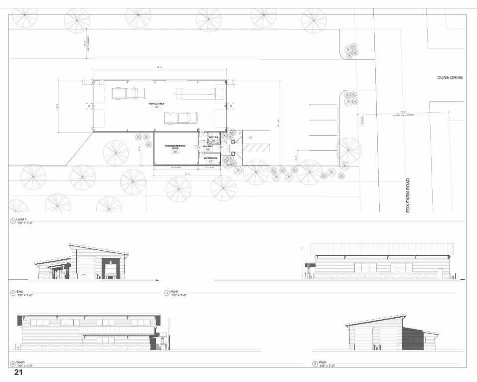
DUNE DRIVE
FOX
FAR
M R
OAD
10' -
0"
COUNTRY ROAD EASEMENT
60' - 0"
UTI
LIT Y
E ASE
MEN
T
20'-
0 "
56'-
23/
8"
88' - 0"
3'-0
"
3'-0
"
107
109
110
111
4' - 0"
14' - 4 5/16"
5' - 9"
44' - 0"
34'-
3" VEHICLE AREA105
TRAINING/MEETINGROOM
106
MECHANICAL107
REST RM108
HALLWAY109
113
114
6"
28' - 6 15/16"
20'-
119/
32"
21'-
9"
15 Fifth Street SouthGreat Falls, Montana 59401
Phone (406) 771-0770
L'HeureuxPage WernerARCHITECTURE ENGINEERING
SHEETNUMBER:
PROJECT NUMBER:
DATE:
CHECKED BY:
DRAWN BY:
THIS DRAWING IS THE PROPERTY OF THE ARCHITECT.IT HAS BEEN PREPARED SPECIFICALLY FOR THIS SITEAND IS NOT TO BE USED FOR ANY OTHER PURPOSE,
LOCATION, OR OWNER WITHOUT WRITTEN CONSENT OFTHE ARCHITECT.
C 2009 L'HEUREUX, PAGE, WERNER, PC
No. DateSubmittals
7/28/2011 1:25:42 PM
M1.200-000
Author
Checker
Unn
amed
proj
ect n
ame
Revision ScheduleNo. Revision Date
1/8" = 1'-0"1 Level 1
1/8" = 1'-0"2 East
1/8" = 1'-0"3 North
1/8" = 1'-0"4 South
1/8" = 1'-0"5 West
21

Sliding conference room door. Metal sign was CNC routed at a nearby shop. Cutouts in the oth-er metal panel eventually are filled with a piece of fused glass. Door was later hung mounted with rollers on the top and wheels on the bottom.
//
MO
SA
IC
S
um
me
r
20
08
22