
Wen-Chang Tsai Peng-Cheng Yu and Shyue-bin Chang Advanced ... · stringent emission regulations,...
14
Design of Electrical Driving Circuits for a High-pressure Fuel Injector and Control of Fuel Injection Quantities by using the Polynomial Curve Fitting Method Wen-Chang Tsai, Zong-Hua Wu, Peng-Cheng Yu and Shyue-bin Chang International Journal of Intelligent Information Processing Volume 2, Number 2, June 2011 Design of Electrical Driving Circuits for a High-pressure Fuel Injector and Control of Fuel Injection Quantities by using the Polynomial Curve Fitting Method Wen-Chang Tsai 1&2 , Zong-Hua Wu 1&2 , Peng-Cheng Yu 1&2 and Shyue-bin Chang 1 1 Advanced Engine Research Center, 2 Department of Electrical Engineering, Kao Yuan University Luju 82151, Kaohsiung County, Taiwan [email protected] doi : 10.4256/ijiip.vol2.issue2.7 Abstract Various electric driving circuits for the high-pressure (H.P.) GDI injector are required to be designed to be capable of rapid response and precise air-fuel ratio control for GDI engines. In this study, power transistors, IGBTs and power MOSFETs components are adopted respectively to design the electrical driving circuits for the H.P. GDI injector. The designed injector driving circuits are tested to verify its feasibility. The experiments for the GDI injection quantities are conducted under 60-100 bar fuel pressures, 1200~2000μs injecting pulse durations and DC 65V executing supply voltages. Also, the experimental fuel injection quantities of the high-pressure injector fed by the three-stage MOSFETs driving circuits can be modeled by using the polynomial curve fitting method. The polynomial m fuel (t p ) equation of degree n fits the data of fuel injection quantities at different engine operating conditions. The fuel injection curve equations can be derived and implemented in developing the ECU to demonstrate its ability to control the fuel injection quantities and injection timing rapidly and precisely. Keywords: Electrical Driving Circuit, Electronic Control Unit (ECU), Gasoline Direct Injection (GDI), Motorcycle Engine 1. Introduction In order to achieve fuel economy, superior driving performance, and meet the requirements of stringent emission regulations, the development of four-stroke, spark-ignition engines to inject gasoline directly into the combustion chamber is an important technology of the automotive and motorcycle industries [1]. Many modern electronic injection technologies have been developed to implement in various investigations of GDI engines. The electronically controlled injector is the key component in the high pressure GDI fuel injection system. It is essential to determine the dynamic performances of a GDI injector for developing the high pressure GDI fuel injection system [2-3]. Also, a number of control strategies have been reported in the literature during the recent decade. Most of these control schemes deal with manifold pressure control, air-fuel ratio control and idle speed control [4-5]. A controller for air and fuel control is designed using equations on the basis of a high pressure fuel injection system model [6]. The application of PC-based control schemes for torque and air-fuel ratio control is proposed in [7-8]. Therefore, characterizing the dynamic performances of the H.P. injector is essential to the implementation of GDI engine air-fuel ratio control. The computer simulation and experimental analysis is an effective way to define the characterizations of the GDI injectors that can be fitted to a high pressure fuel injection system. These injector’s curves and parameters are advantageous to achieve the precise air-fuel ratio control of engines. The relationship between injector parameters and its performance is analyzed through simulation, and then optimized. Various electrical driving circuit designs for the H.P. injector are proposed [9-10] and the experimental tests of the high pressure fuel injection system are investigated [2,11]. In this study, various electrical driving circuits are designed to satisfy the rapid response of various H.P. GDI injectors and sustain the instantaneous turn-on surge current. The designed electric driving - 60 -
Transcript of Wen-Chang Tsai Peng-Cheng Yu and Shyue-bin Chang Advanced ... · stringent emission regulations,...
Design of Electrical Driving Circuits for a High-pressure Fuel Injector and Control of Fuel Injection Quantities by using the Polynomial Curve Fitting Method
Wen-Chang Tsai, Zong-Hua Wu, Peng-Cheng Yu and Shyue-bin Chang
International Journal of Intelligent Information Processing Volume 2, Number 2, June 2011
Design of Electrical Driving Circuits for a High-pressure Fuel Injector and Control of Fuel Injection Quantities by using the Polynomial Curve Fitting
Method
Wen-Chang Tsai1&2, Zong-Hua Wu1&2, Peng-Cheng Yu1&2 and Shyue-bin Chang1 1Advanced Engine Research Center, 2Department of Electrical Engineering,
Kao Yuan University Luju 82151, Kaohsiung County, Taiwan
[email protected] doi : 10.4256/ijiip.vol2.issue2.7
Abstract
Various electric driving circuits for the high-pressure (H.P.) GDI injector are required to be designed to be capable of rapid response and precise air-fuel ratio control for GDI engines. In this study, power transistors, IGBTs and power MOSFETs components are adopted respectively to design the electrical driving circuits for the H.P. GDI injector. The designed injector driving circuits are tested to verify its feasibility. The experiments for the GDI injection quantities are conducted under 60-100 bar fuel pressures, 1200~2000μs injecting pulse durations and DC 65V executing supply voltages. Also, the experimental fuel injection quantities of the high-pressure injector fed by the three-stage MOSFETs driving circuits can be modeled by using the polynomial curve fitting method. The polynomial mfuel(tp) equation of degree n fits the data of fuel injection quantities at different engine operating conditions. The fuel injection curve equations can be derived and implemented in developing the ECU to demonstrate its ability to control the fuel injection quantities and injection timing rapidly and precisely.
Keywords: Electrical Driving Circuit, Electronic Control Unit (ECU),
Gasoline Direct Injection (GDI), Motorcycle Engine 1. Introduction
In order to achieve fuel economy, superior driving performance, and meet the requirements of
stringent emission regulations, the development of four-stroke, spark-ignition engines to inject gasoline directly into the combustion chamber is an important technology of the automotive and motorcycle industries [1]. Many modern electronic injection technologies have been developed to implement in various investigations of GDI engines. The electronically controlled injector is the key component in the high pressure GDI fuel injection system. It is essential to determine the dynamic performances of a GDI injector for developing the high pressure GDI fuel injection system [2-3]. Also, a number of control strategies have been reported in the literature during the recent decade. Most of these control schemes deal with manifold pressure control, air-fuel ratio control and idle speed control [4-5]. A controller for air and fuel control is designed using equations on the basis of a high pressure fuel injection system model [6]. The application of PC-based control schemes for torque and air-fuel ratio control is proposed in [7-8]. Therefore, characterizing the dynamic performances of the H.P. injector is essential to the implementation of GDI engine air-fuel ratio control. The computer simulation and experimental analysis is an effective way to define the characterizations of the GDI injectors that can be fitted to a high pressure fuel injection system. These injector’s curves and parameters are advantageous to achieve the precise air-fuel ratio control of engines. The relationship between injector parameters and its performance is analyzed through simulation, and then optimized. Various electrical driving circuit designs for the H.P. injector are proposed [9-10] and the experimental tests of the high pressure fuel injection system are investigated [2,11].
In this study, various electrical driving circuits are designed to satisfy the rapid response of various H.P. GDI injectors and sustain the instantaneous turn-on surge current. The designed electric driving
- 60 -
Design of Electrical Driving Circuits for a High-pressure Fuel Injector and Control of Fuel Injection Quantities by using the Polynomial Curve Fitting Method
Wen-Chang Tsai, Zong-Hua Wu, Peng-Cheng Yu and Shyue-bin Chang
International Journal of Intelligent Information Processing Volume 2, Number 2, June 2011
circuits are tested to verify its feasibility. The experiments for the GDI injection quantities are conducted under 60-100 bar fuel pressure, 1200~2000μs injecting pulse duration and DC 40~70V executing supply voltage. Next, PWM control is introduced to the last pulse holding current in the three-stage power MOSFETs driving circuit for the rapid response to turn off the H.P. GDI injector. Also, the dynamic performances of the GDI injector can be characterized as the fuel injection curves. The polynomial mfuel(tp) equations of degree n are derived from these fuel injection curves and implemented in developing the ECU to demonstrate its ability to control the fuel injection quantities and injection timing rapidly and precisely.
2. The High-pressure GDI Fuel Injection System
In-cylinder direct injection technology is a superior option due to its advantages in potential fuel
economy and emission reduction. One of the most important technologies is the GDI fuel injecting system, of which the H.P. injector is the central component. A H.P. fuel supply system of GDI engines directly injects fuel to the cylinder of the engine. The injecting timing and duration is electronically controlled by the Electronic control unit (ECU). Various pulse durations can be sent to the fuel injector according to the engine’s actual operating conditions from the signals of engine sensors. The H.P. fuel injection system mainly comprises of four parts: the fuel supply system, electronic control unit (ECU), electrical driving circuit and an injector. The fuel supply system provides a constant 60-100 bar pressure resource for the injector. The injection pulse duration and timing of the injector are controlled by using an electronic control unit (ECU), which computes and analyzes the analogue and digital input signals from various engine sensors. The engine performances can be improved by more rapid engine response in throttle positions, and more precise control of air/fuel ratio. In this study, a Bosch GDI single-hole injector is installed and tested on the cylinder head of a 500cc motorcycle engine.
2.1. Fuel Supply System
The fuel supply system is similar to the conventional design of GDI engines in H.P. fuel containers.
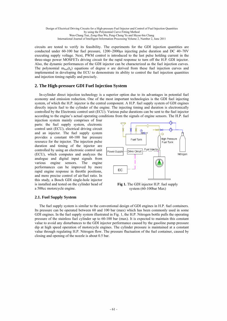
Its pressure can be operated between 60 and 100 bar (max) which has been commonly used in some GDI engines. In the fuel supply system illustrated in Fig. 1, the H.P. Nitrogen bottle pulls the operating pressure of the stainless fuel cylinder up to 60-100 bar (max). It is expected to maintain this constant value to avoid any disturbances to the GDI injector performance caused by the gasoline pump pressure dip at high speed operation of motorcycle engines. The cylinder pressure is maintained at a constant value through regulating H.P. Nitrogen flow. The pressure fluctuation of the fuel container, caused by closing and opening of the nozzle is about 0.5 bar.
Fig 1. The GDI injector H.P. fuel supply system (60-100bar Max)
EC
- 61 -
Design of Electrical Driving Circuits for a High-pressure Fuel Injector and Control of Fuel Injection Quantities by using the Polynomial Curve Fitting Method
Wen-Chang Tsai, Zong-Hua Wu, Peng-Cheng Yu and Shyue-bin Chang
International Journal of Intelligent Information Processing Volume 2, Number 2, June 2011
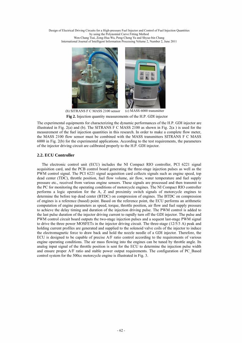
The experimental equipments for characterizing the dynamic performances of the H.P. GDI injector are illustrated in Fig. 2(a) and (b). The SITRANS F C MASS 2100 as shown in Fig. 2(a ) is used for the measurement of the fuel injection quantities in this research. In order to make a complete flow meter, the MASS 2100 flow sensor must be combined with the MASS transmitters SITRANS F C MASS 6000 in Fig. 2(b) for the experimental applications. According to the test requirements, the parameters of the injector driving circuit are calibrated properly to the H.P. GDI injector.
2.2. ECU Controller
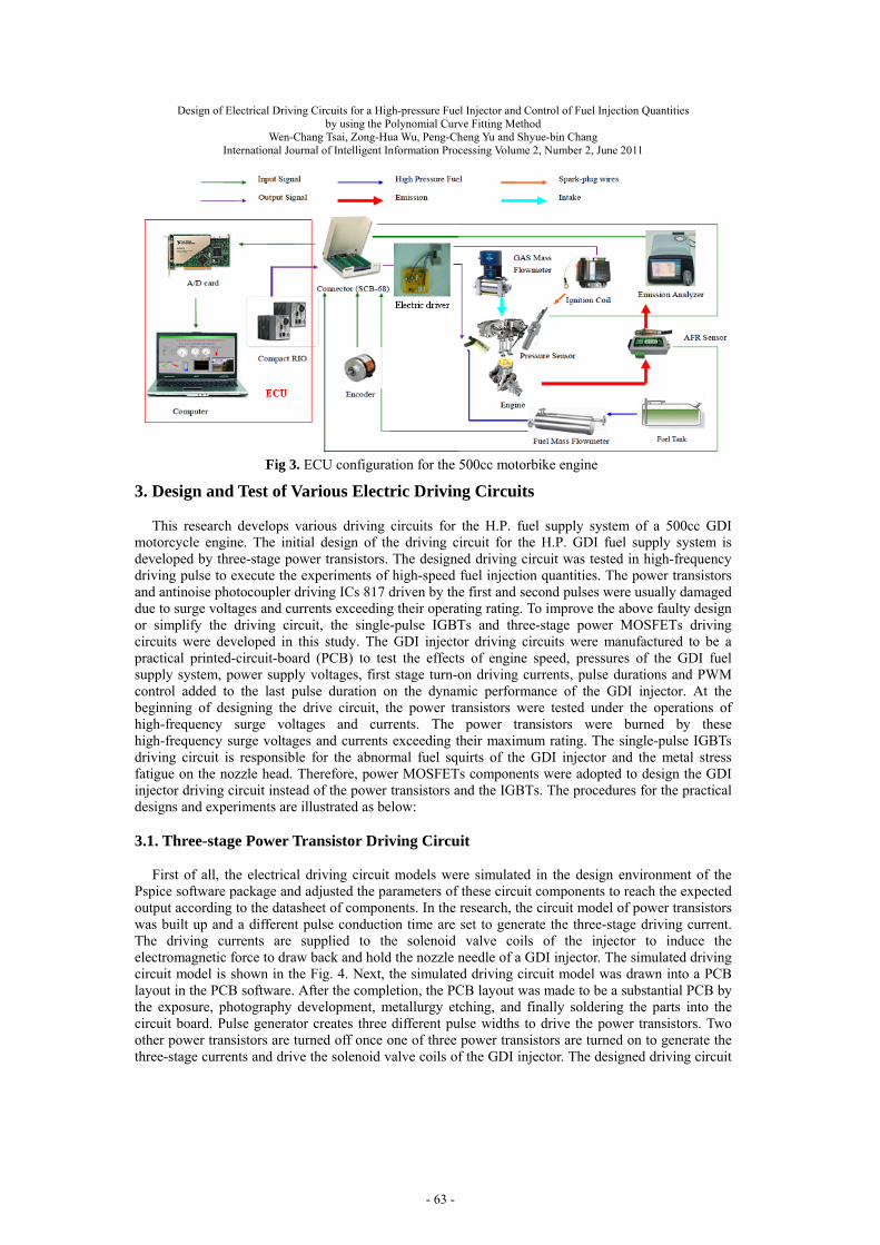
The electronic control unit (ECU) includes the NI Compact RIO controller, PCI 6221 signal
acquisition card, and the PCB control board generating the three-stage injection pulses as well as the PWM control signal. The PCI 6221 signal acquisition card collects signals such as engine speed, top dead center (TDC), throttle position, fuel flow volume, air flow, water temperature and fuel supply pressure etc., received from various engine sensors. These signals are processed and then transmit to the PC for monitoring the operating conditions of motorcycle engines. The NI Compact RIO controller performs a logic operation for the A, Z and proximity switch signals of motorcycle engines to determine the before top dead center (BTDC) on compression of engines. The BTDC on compression of engines is a reference (based) point. Based on the reference point, the ECU performs an arithmetic computation of engine parameters as speed, torque, throttle position, air flow and fuel supply pressure to achieve the delay timing and duration of the injection driving pulse. The PWM control is added to the last pulse duration of the injector driving current to rapidly turn off the GDI injector. The pulse and PWM control circuit board outputs the two-stage injection pulses and a sequent last-stage PWM signal to drive the three power MOSFETs in the injector driving circuit. The three-stage (12/5/3 A) peak and holding current profiles are generated and supplied to the solenoid valve coils of the injector to induce the electromagnetic force to draw back and hold the nozzle needle of a GDI injector. Therefore, the ECU is designed to be capable of precise A/F ratio control according to the requirements of various engine operating conditions. The air mass flowing into the engines can be tuned by throttle angle. Its analog input signal of the throttle position is sent for the ECU to determine the injection pulse width and ensure proper A/F ratio and stable power output requirements. The configuration of PC_Based control system for the 500cc motorcycle engine is illustrated in Fig. 3.
(b) SITRANS F C MASS 2100 sensor (c) MASS 6000 transmitter
Fig 2. Injection quantity measurements of the H.P. GDI injector
- 62 -
Design of Electrical Driving Circuits for a High-pressure Fuel Injector and Control of Fuel Injection Quantities by using the Polynomial Curve Fitting Method
Wen-Chang Tsai, Zong-Hua Wu, Peng-Cheng Yu and Shyue-bin Chang
International Journal of Intelligent Information Processing Volume 2, Number 2, June 2011
3. Design and Test of Various Electric Driving Circuits
This research develops various driving circuits for the H.P. fuel supply system of a 500cc GDI
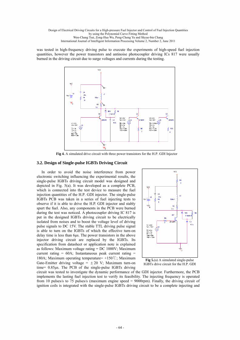
motorcycle engine. The initial design of the driving circuit for the H.P. GDI fuel supply system is developed by three-stage power transistors. The designed driving circuit was tested in high-frequency driving pulse to execute the experiments of high-speed fuel injection quantities. The power transistors and antinoise photocoupler driving ICs 817 driven by the first and second pulses were usually damaged due to surge voltages and currents exceeding their operating rating. To improve the above faulty design or simplify the driving circuit, the single-pulse IGBTs and three-stage power MOSFETs driving circuits were developed in this study. The GDI injector driving circuits were manufactured to be a practical printed-circuit-board (PCB) to test the effects of engine speed, pressures of the GDI fuel supply system, power supply voltages, first stage turn-on driving currents, pulse durations and PWM control added to the last pulse duration on the dynamic performance of the GDI injector. At the beginning of designing the drive circuit, the power transistors were tested under the operations of high-frequency surge voltages and currents. The power transistors were burned by these high-frequency surge voltages and currents exceeding their maximum rating. The single-pulse IGBTs driving circuit is responsible for the abnormal fuel squirts of the GDI injector and the metal stress fatigue on the nozzle head. Therefore, power MOSFETs components were adopted to design the GDI injector driving circuit instead of the power transistors and the IGBTs. The procedures for the practical designs and experiments are illustrated as below: 3.1. Three-stage Power Transistor Driving Circuit
First of all, the electrical driving circuit models were simulated in the design environment of the Pspice software package and adjusted the parameters of these circuit components to reach the expected output according to the datasheet of components. In the research, the circuit model of power transistors was built up and a different pulse conduction time are set to generate the three-stage driving current. The driving currents are supplied to the solenoid valve coils of the injector to induce the electromagnetic force to draw back and hold the nozzle needle of a GDI injector. The simulated driving circuit model is shown in the Fig. 4. Next, the simulated driving circuit model was drawn into a PCB layout in the PCB software. After the completion, the PCB layout was made to be a substantial PCB by the exposure, photography development, metallurgy etching, and finally soldering the parts into the circuit board. Pulse generator creates three different pulse widths to drive the power transistors. Two other power transistors are turned off once one of three power transistors are turned on to generate the three-stage currents and drive the solenoid valve coils of the GDI injector. The designed driving circuit
Fig 3. ECU configuration for the 500cc motorbike engine
- 63 -
Design of Electrical Driving Circuits for a High-pressure Fuel Injector and Control of Fuel Injection Quantities by using the Polynomial Curve Fitting Method
Wen-Chang Tsai, Zong-Hua Wu, Peng-Cheng Yu and Shyue-bin Chang
International Journal of Intelligent Information Processing Volume 2, Number 2, June 2011
was tested in high-frequency driving pulse to execute the experiments of high-speed fuel injection quantities, however the power transistors and antinoise photocoupler driving ICs 817 were usually burned in the driving circuit due to surge voltages and currents during the testing.
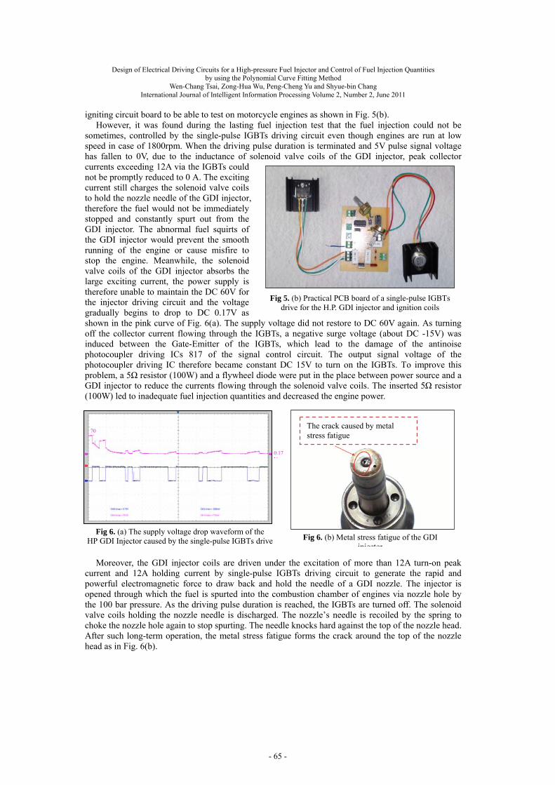
3.2. Design of Single-pulse IGBTs Driving Circuit
In order to avoid the noise interference from power electronic switching influencing the experimental results, the single-pulse IGBTs driving circuit model was designed and depicted in Fig. 5(a). It was developed as a complete PCB, which is connected into the test device to measure the fuel injection quantities of the H.P. GDI injector. The single-pulse IGBTs PCB was taken in a series of fuel injecting tests to observe if it is able to drive the H.P. GDI injector and stably spurt the fuel. Also, any components in the PCB were burned during the test was noticed. A photocoupler driving IC 817 is put in the designed IGBTs driving circuit to be electrically isolated from noises and to boost the voltage level of driving pulse signals to DC 15V. The stable TTL driving pulse signal is able to turn on the IGBTs of which the effective turn-on delay time is less than 6μs. The power transistors in the above injector driving circuit are replaced by the IGBTs. Its specification from datasheet or application note is explained as follows: Maximum voltage rating = DC 1000V; Maximum current rating = 60A; Instantaneous peak current rating = 180A; Maximum operating temperature= +150; Maximum Gate-Emitter driving voltage = 20 V; Maximum turn-on time= 0.85μs. The PCB of the single-pulse IGBTs driving circuit was tested to investigate the dynamic performance of the GDI injector. Furthermore, the PCB implements the lasting fuel injection test to verify its feasibility. The injecting frequency is operated from 10 pulses/s to 75 pulses/s (maximum engine speed = 9000rpm). Finally, the driving circuit of ignition coils is integrated with the single-pulse IGBTs driving circuit to be a complete injecting and
Fig 5.(a) A simulated single-pulse IGBTs drive circuit for the H.P. GDI
Fig 4. A simulated drive circuit with three power transistors for the H.P. GDI Injector
- 64 -
Design of Electrical Driving Circuits for a High-pressure Fuel Injector and Control of Fuel Injection Quantities by using the Polynomial Curve Fitting Method
Wen-Chang Tsai, Zong-Hua Wu, Peng-Cheng Yu and Shyue-bin Chang
International Journal of Intelligent Information Processing Volume 2, Number 2, June 2011
igniting circuit board to be able to test on motorcycle engines as shown in Fig. 5(b).
However, it was found during the lasting fuel injection test that the fuel injection could not be sometimes, controlled by the single-pulse IGBTs driving circuit even though engines are run at low speed in case of 1800rpm. When the driving pulse duration is terminated and 5V pulse signal voltage has fallen to 0V, due to the inductance of solenoid valve coils of the GDI injector, peak collector currents exceeding 12A via the IGBTs could not be promptly reduced to 0 A. The exciting current still charges the solenoid valve coils to hold the nozzle needle of the GDI injector, therefore the fuel would not be immediately stopped and constantly spurt out from the GDI injector. The abnormal fuel squirts of the GDI injector would prevent the smooth running of the engine or cause misfire to stop the engine. Meanwhile, the solenoid valve coils of the GDI injector absorbs the large exciting current, the power supply is therefore unable to maintain the DC 60V for the injector driving circuit and the voltage gradually begins to drop to DC 0.17V as shown in the pink curve of Fig. 6(a). The supply voltage did not restore to DC 60V again. As turning off the collector current flowing through the IGBTs, a negative surge voltage (about DC -15V) was induced between the Gate-Emitter of the IGBTs, which lead to the damage of the antinoise photocoupler driving ICs 817 of the signal control circuit. The output signal voltage of the photocoupler driving IC therefore became constant DC 15V to turn on the IGBTs. To improve this problem, a 5Ω resistor (100W) and a flywheel diode were put in the place between power source and a GDI injector to reduce the currents flowing through the solenoid valve coils. The inserted 5Ω resistor (100W) led to inadequate fuel injection quantities and decreased the engine power.
Moreover, the GDI injector coils are driven under the excitation of more than 12A turn-on peak
current and 12A holding current by single-pulse IGBTs driving circuit to generate the rapid and powerful electromagnetic force to draw back and hold the needle of a GDI nozzle. The injector is opened through which the fuel is spurted into the combustion chamber of engines via nozzle hole by the 100 bar pressure. As the driving pulse duration is reached, the IGBTs are turned off. The solenoid valve coils holding the nozzle needle is discharged. The nozzle’s needle is recoiled by the spring to choke the nozzle hole again to stop spurting. The needle knocks hard against the top of the nozzle head. After such long-term operation, the metal stress fatigue forms the crack around the top of the nozzle head as in Fig. 6(b).
Fig 5. (b) Practical PCB board of a single-pulse IGBTs drive for the H.P. GDI injector and ignition coils
70V
0.17V
The crack caused by metal stress fatigue
Fig 6. (a) The supply voltage drop waveform of the HP GDI Injector caused by the single-pulse IGBTs drive Fig 6. (b) Metal stress fatigue of the GDI
injector
- 65 -
Design of Electrical Driving Circuits for a High-pressure Fuel Injector and Control of Fuel Injection Quantities by using the Polynomial Curve Fitting Method
Wen-Chang Tsai, Zong-Hua Wu, Peng-Cheng Yu and Shyue-bin Chang
International Journal of Intelligent Information Processing Volume 2, Number 2, June 2011
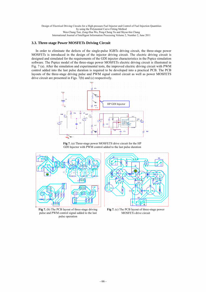
3.3. Three-stage Power MOSFETs Driving Circuit
In order to eliminate the defects of the single-pulse IGBTs driving circuit, the three-stage power
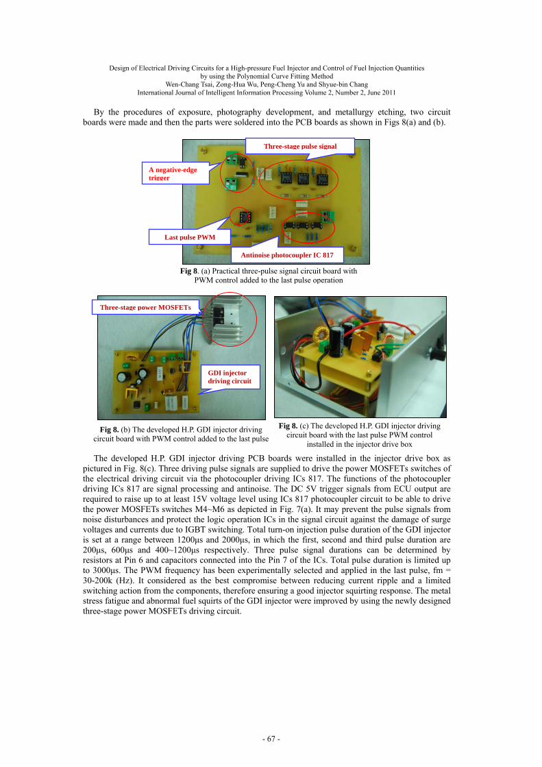
MOSFETs is introduced in the design of the injector driving circuit. The electric driving circuit is designed and simulated for the requirements of the GDI injector characteristics in the Pspice simulation software. The Pspice model of the three-stage power MOSFETs electric driving circuit is illustrated in Fig. 7 (a). After the simulation and experimental tests, the improved electric driving circuit with PWM control added into the last pulse duration is required to be developed into a practical PCB. The PCB layouts of the three-stage driving pulse and PWM signal control circuit as well as power MOSFETS drive circuit are presented in Figs. 7(b) and (c) respectively.
Fig 7. (a) Three-stage power MOSFETS drive circuit for the HP GDI Injector with PWM control added to the last pulse duration
HP GDI Injector
Fig 7. (b) The PCB layout of three-stage driving pulse and PWM control signal added to the last
pulse operation
Fig 7. (c) The PCB layout of three-stage power MOSFETs drive circuit
- 66 -
Design of Electrical Driving Circuits for a High-pressure Fuel Injector and Control of Fuel Injection Quantities by using the Polynomial Curve Fitting Method
Wen-Chang Tsai, Zong-Hua Wu, Peng-Cheng Yu and Shyue-bin Chang
International Journal of Intelligent Information Processing Volume 2, Number 2, June 2011
Fig 8. (a) Practical three-pulse signal circuit board with PWM control added to the last pulse operation
Antinoise photocoupler IC 817
Last pulse PWM
Three-stage pulse signal
A negative-edge trigger
Fig 8. (c) The developed H.P. GDI injector driving circuit board with the last pulse PWM control
installed in the injector drive box
By the procedures of exposure, photography development, and metallurgy etching, two circuit boards were made and then the parts were soldered into the PCB boards as shown in Figs 8(a) and (b).
The developed H.P. GDI injector driving PCB boards were installed in the injector drive box as
pictured in Fig. 8(c). Three driving pulse signals are supplied to drive the power MOSFETs switches of the electrical driving circuit via the photocoupler driving ICs 817. The functions of the photocoupler driving ICs 817 are signal processing and antinoise. The DC 5V trigger signals from ECU output are required to raise up to at least 15V voltage level using ICs 817 photocoupler circuit to be able to drive the power MOSFETs switches M4~M6 as depicted in Fig. 7(a). It may prevent the pulse signals from noise disturbances and protect the logic operation ICs in the signal circuit against the damage of surge voltages and currents due to IGBT switching. Total turn-on injection pulse duration of the GDI injector is set at a range between 1200μs and 2000μs, in which the first, second and third pulse duration are 200μs, 600μs and 400~1200μs respectively. Three pulse signal durations can be determined by resistors at Pin 6 and capacitors connected into the Pin 7 of the ICs. Total pulse duration is limited up to 3000μs. The PWM frequency has been experimentally selected and applied in the last pulse, fm = 30-200k (Hz). It considered as the best compromise between reducing current ripple and a limited switching action from the components, therefore ensuring a good injector squirting response. The metal stress fatigue and abnormal fuel squirts of the GDI injector were improved by using the newly designed three-stage power MOSFETs driving circuit.
Fig 8. (b) The developed H.P. GDI injector driving circuit board with PWM control added to the last pulse
GDI injector driving circuit
Three-stage power MOSFETs
- 67 -
Design of Electrical Driving Circuits for a High-pressure Fuel Injector and Control of Fuel Injection Quantities by using the Polynomial Curve Fitting Method
Wen-Chang Tsai, Zong-Hua Wu, Peng-Cheng Yu and Shyue-bin Chang
International Journal of Intelligent Information Processing Volume 2, Number 2, June 2011
4. Results and Discussions
The electrical driving circuit is installed and tested in the GDI injecting system as illustrates in Fig 1.
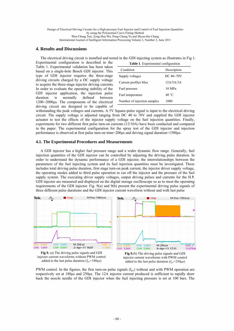
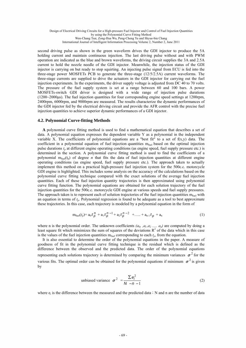
Experimental configuration is described in the Table 1. Experimental validation has been taken based on a single-hole Bosch GDI injector. This type of GDI injector requires the three-stage driving circuits charged by a DC supply voltage to acquire the three-stage injector driving currents. In order to evaluate the operating stability of the GDI injector application, the injection pulse duration is normally defined between 1200~2000μs. The components of the electrical driving circuit are designed to be capable of withstanding the peak voltages and currents. A 5V Square-pulse signal is input to the electrical driving circuit. The supply voltage is adjusted ranging from DC 40 to 70V and supplied the GDI injector actuator to test the effects of the injector supply voltage on the fuel injection quantities. Finally, experiments for two different first pulse turn-on currents (12/10A) have been conducted and compared in the paper. The experimental configuration for the spray test of the GDI injector and injection performance is observed at first pulse turn-on time=200μs and driving signal duration=1500μs.
4.1. The Experimental Procedures and Measurements
A GDI injector has a higher fuel pressure range and a wider dynamic flow range. Generally, fuel injection quantities of the GDI injector can be controlled by adjusting the driving pulse duration. In order to understand the dynamic performance of a GDI injector, the interrelationships between the parameters of the fuel injecting system and its fuel injection quantities must be investigated. These includes total driving pulse duration, first stage turn-on peak current, the injector driver supply voltage, the operating modes added to third pulse operation to cut off the injector and the pressure of the fuel supply system. The executing driver supply voltages, output driving pulses and currents for the H.P. GDI injector are measured and displayed on the digital storage oscilloscope so as to meet the operating requirements of the GDI injector. Fig. 9(a) and 9(b) present the experimental driving pulse signals of three different pulse durations and the GDI injector current waveform without and with last pulse
PWM control. In the figures, the first turn-on pulse signals (Ip1) without and with PWM operation are respectively set at 180μs and 250μs. The 12A injector current produced is sufficient to rapidly draw back the nozzle needle of the GDI injector when the fuel injecting pressure is set at 100 bars. The
Table 1. Experimental configuration
Condition Description
Supply voltages DC 40~70V
Current profiles Max 12A/5A/3A
Fuel pressure 10 MPa
Fuel temperature 40 °C
Number of injection samples 1000
Fig 9.(b) The driving pulse signals and GDI injector current waveforms with PWM control
added to the last pulse duration (Ip1=250μs)
Fig 9. (a) The driving pulse signals and GDI injector current waveforms without PWM control
added to the last pulse duration (Ip1=180μs)
- 68 -
Design of Electrical Driving Circuits for a High-pressure Fuel Injector and Control of Fuel Injection Quantities by using the Polynomial Curve Fitting Method
Wen-Chang Tsai, Zong-Hua Wu, Peng-Cheng Yu and Shyue-bin Chang
International Journal of Intelligent Information Processing Volume 2, Number 2, June 2011
second driving pulse as shown in the green waveform drives the GDI injector to produce the 5A holding current and maintain continuous injection. The last driving pulse without and with PWM operation are indicated as the blue and brown waveforms, the driving circuit supplies the 3A and 2.5A current to hold the nozzle needle of the GDI injector. Meanwhile, the injection status of the GDI injector is carrying on but ready to stop squirting. An injecting pulse signal from ECU is fed into the three-stage power MOSFETs PCB to generate the three-stage (12/5/2.5A) current waveforms. The three-stage currents are supplied to drive the actuators in the GDI injector for carrying out the fuel injection experiments. In the experiments, the driver supply voltage is adjusted from DC 40 to 70 volts. The pressure of the fuel supply system is set at a range between 60 and 100 bars. A power MOSFETs-switch GDI driver is designed with a wide range of injection pulse durations (1200~2000μs). The fuel injection quantities for four corresponding engine speed settings at 1200rpm, 2400rpm, 6000rpm, and 9000rpm are measured. The results characterize the dynamic performances of the GDI injector fed by the electrical driving circuit and provide the AFR control with the precise fuel injection quantities to achieve superior dynamic performances of a GDI injector. 4.2. Polynomial Curve-fitting Methods
A polynomial curve fitting method is used to find a mathematical equation that describes a set of
data. A polynomial equation expresses the dependent variable Y as a polynomial in the independent variable X. The coefficients of polynomial equations are a "best fit" to a set of f(x,y) data. The coefficient in a polynomial equation of fuel injection quantities mfuel based on the optimal injection pulse durations tp at different engine operating conditions (as engine speed, fuel supply pressure etc.) is determined in the section. A polynomial curve fitting method is used to find the coefficients of a polynomial mfuel(tp) of degree n that fits the data of fuel injection quantities at different engine operating conditions (as engine speed, fuel supply pressure etc.). The approach taken to actually implement this method on a practical high-pressure fuel injection system for the 500c.c. motorcycle GDI engine is highlighted. This includes some analysis on the accuracy of the calculations based on the polynomial curve fitting technique compared with the exact solutions of the average fuel injection quantities. Each of these fuel injection quantity trajectories is then approximated using polynomial curve fitting function. The polynomial equations are obtained for each solution trajectory of the fuel injection quantities for the 500c.c. motorcycle GDI engine at various speeds and fuel supply pressures. The approach taken is to represent each of solution trajectories of the fuel injection quantities mfuel with an equation in terms of tp. Polynomial regression is found to be adequate as a tool to best approximate these trajectories. In this case, each trajectory is modeled by a polynomial equation in the form of
mfuel(tp)= a0npt + a1
1npt + a2
2npt +….. + an-1 pt + an (1)
where n is the polynomial order. The unknown coefficients (a0, ,al ,a2 ..... an) are computed by doing a least square fit which minimizes the sum of squares of the deviations R2 of the data which in this case is the values of the fuel injection quantities mfuel corresponding to each tp, from the equation.
It is also essential to determine the order of the polynomial equations in the paper. A measure of goodness of fit in the polynomial curve fitting technique is the residual which is defined as the difference between the observed and the predicted data. The order of the polynomial equations
representing each solutions trajectory is determined by comparing the minimum variances 2 for the
various fits. The optimal order can be obtained for the polynomial equations if minimum 2 is given by
unbiased variance 2 =1
2
nN
ei (2)
where ei is the difference between the measured and the predicted data;N and n are the number of data
- 69 -
Design of Electrical Driving Circuits for a High-pressure Fuel Injector and Control of Fuel Injection Quantities by using the Polynomial Curve Fitting Method
Wen-Chang Tsai, Zong-Hua Wu, Peng-Cheng Yu and Shyue-bin Chang
International Journal of Intelligent Information Processing Volume 2, Number 2, June 2011 points included in the fit and the polynomial order respectively. 4.3. Effect of Pulse Width on the Fuel Injection Quantities
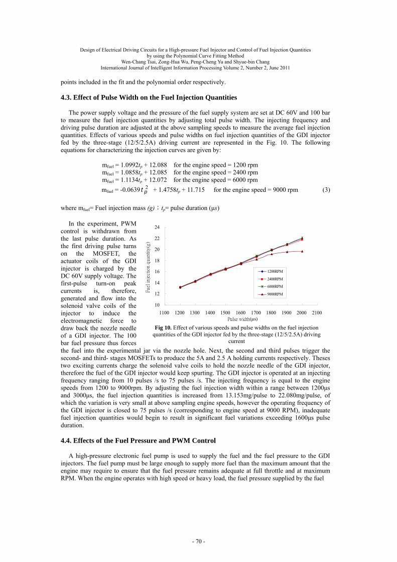
The power supply voltage and the pressure of the fuel supply system are set at DC 60V and 100 bar
to measure the fuel injection quantities by adjusting total pulse width. The injecting frequency and driving pulse duration are adjusted at the above sampling speeds to measure the average fuel injection quantities. Effects of various speeds and pulse widths on fuel injection quantities of the GDI injector fed by the three-stage (12/5/2.5A) driving current are represented in the Fig. 10. The following equations for characterizing the injection curves are given by:
mfuel = 1.0992tp + 12.088 for the engine speed = 1200 rpm mfuel = 1.0858tp + 12.085 for the engine speed = 2400 rpm mfuel = 1.1134tp + 12.072 for the engine speed = 6000 rpm
mfuel = -0.0639 2pt + 1.4758tp + 11.715 for the engine speed = 9000 rpm (3)
where mfuel= Fuel injection mass (g);tp= pulse duration (μs)
In the experiment, PWM
control is withdrawn from the last pulse duration. As the first driving pulse turns on the MOSFET, the actuator coils of the GDI injector is charged by the DC 60V supply voltage. The first-pulse turn-on peak currents is, therefore, generated and flow into the solenoid valve coils of the injector to induce the electromagnetic force to draw back the nozzle needle of a GDI injector. The 100 bar fuel pressure thus forces the fuel into the experimental jar via the nozzle hole. Next, the second and third pulses trigger the second- and third- stages MOSFETs to produce the 5A and 2.5 A holding currents respectively. Theses two exciting currents charge the solenoid valve coils to hold the nozzle needle of the GDI injector, therefore the fuel of the GDI injector would keep spurting. The GDI injector is operated at an injecting frequency ranging from 10 pulses /s to 75 pulses /s. The injecting frequency is equal to the engine speeds from 1200 to 9000rpm. By adjusting the fuel injection width within a range between 1200μs and 3000μs, the fuel injection quantities is increased from 13.153mg/pulse to 22.080mg/pulse, of which the variation is very small at above sampling engine speeds, however the operating frequency of the GDI injector is closed to 75 pulses /s (corresponding to engine speed at 9000 RPM), inadequate fuel injection quantities would begin to result in significant fuel variations exceeding 1600μs pulse duration.
4.4. Effects of the Fuel Pressure and PWM Control
A high-pressure electronic fuel pump is used to supply the fuel and the fuel pressure to the GDI injectors. The fuel pump must be large enough to supply more fuel than the maximum amount that the engine may require to ensure that the fuel pressure remains adequate at full throttle and at maximum RPM. When the engine operates with high speed or heavy load, the fuel pressure supplied by the fuel
Fig 10. Effect of various speeds and pulse widths on the fuel injection quantities of the GDI injector fed by the three-stage (12/5/2.5A) driving
current
10
12
14
16
18
20
22
24
1100 1200 1300 1400 1500 1600 1700 1800 1900 2000 2100Pulse width(μs)
Fue
l in
ject
ion
qua
ntity
(g)
1200RPM
2400RPM
6000RPM
9000RPM
- 70 -
Design of Electrical Driving Circuits for a High-pressure Fuel Injector and Control of Fuel Injection Quantities by using the Polynomial Curve Fitting Method
Wen-Chang Tsai, Zong-Hua Wu, Peng-Cheng Yu and Shyue-bin Chang
International Journal of Intelligent Information Processing Volume 2, Number 2, June 2011
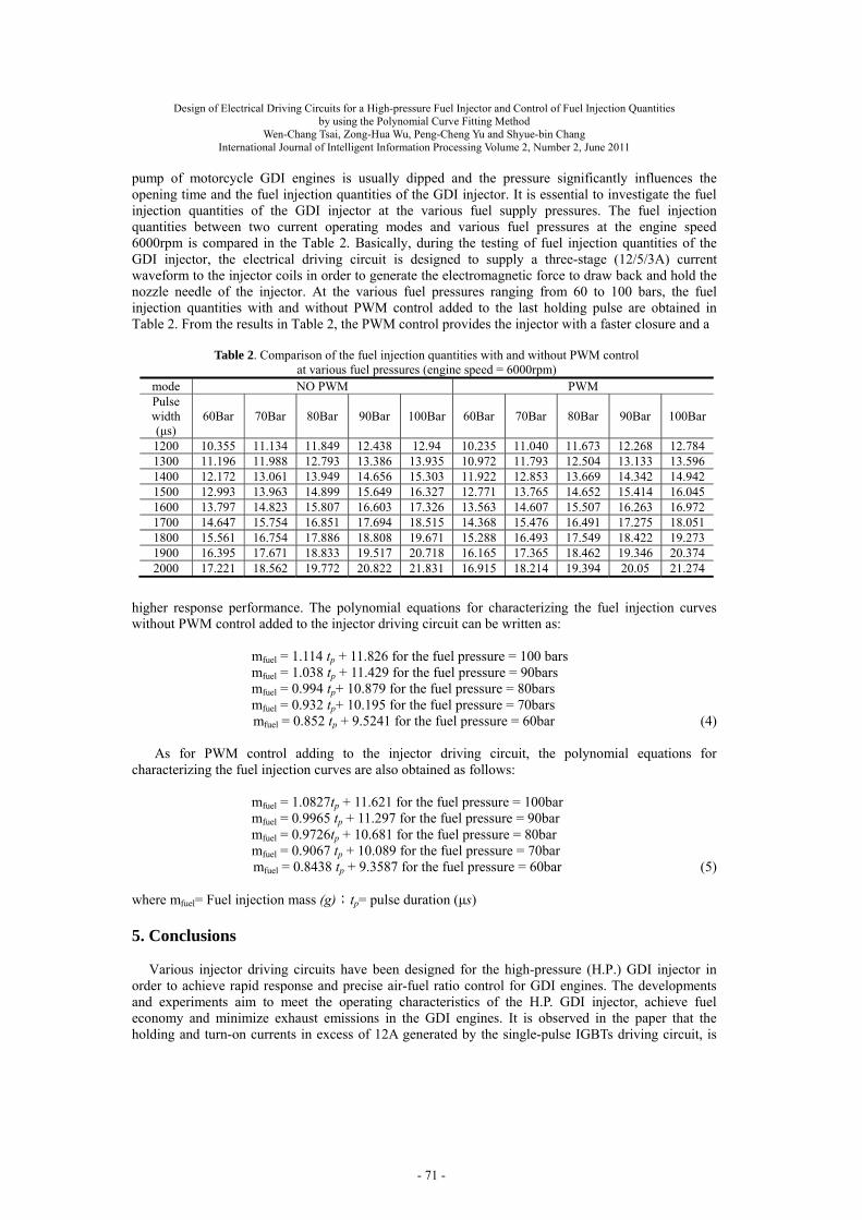
pump of motorcycle GDI engines is usually dipped and the pressure significantly influences the opening time and the fuel injection quantities of the GDI injector. It is essential to investigate the fuel injection quantities of the GDI injector at the various fuel supply pressures. The fuel injection quantities between two current operating modes and various fuel pressures at the engine speed 6000rpm is compared in the Table 2. Basically, during the testing of fuel injection quantities of the GDI injector, the electrical driving circuit is designed to supply a three-stage (12/5/3A) current waveform to the injector coils in order to generate the electromagnetic force to draw back and hold the nozzle needle of the injector. At the various fuel pressures ranging from 60 to 100 bars, the fuel injection quantities with and without PWM control added to the last holding pulse are obtained in Table 2. From the results in Table 2, the PWM control provides the injector with a faster closure and a
higher response performance. The polynomial equations for characterizing the fuel injection curves without PWM control added to the injector driving circuit can be written as:
mfuel = 1.114 tp + 11.826 for the fuel pressure = 100 bars mfuel = 1.038 tp + 11.429 for the fuel pressure = 90bars mfuel = 0.994 tp+ 10.879 for the fuel pressure = 80bars mfuel = 0.932 tp+ 10.195 for the fuel pressure = 70bars
mfuel = 0.852 tp + 9.5241 for the fuel pressure = 60bar (4) As for PWM control adding to the injector driving circuit, the polynomial equations for
characterizing the fuel injection curves are also obtained as follows:
mfuel = 1.0827tp + 11.621 for the fuel pressure = 100bar mfuel = 0.9965 tp + 11.297 for the fuel pressure = 90bar mfuel = 0.9726tp + 10.681 for the fuel pressure = 80bar mfuel = 0.9067 tp + 10.089 for the fuel pressure = 70bar
mfuel = 0.8438 tp + 9.3587 for the fuel pressure = 60bar (5) where mfuel= Fuel injection mass (g);tp= pulse duration (μs)
5. Conclusions
Various injector driving circuits have been designed for the high-pressure (H.P.) GDI injector in
order to achieve rapid response and precise air-fuel ratio control for GDI engines. The developments and experiments aim to meet the operating characteristics of the H.P. GDI injector, achieve fuel economy and minimize exhaust emissions in the GDI engines. It is observed in the paper that the holding and turn-on currents in excess of 12A generated by the single-pulse IGBTs driving circuit, is
Table 2. Comparison of the fuel injection quantities with and without PWM control at various fuel pressures (engine speed = 6000rpm)
mode NO PWM PWM Pulse width (μs)
60Bar 70Bar 80Bar 90Bar 100Bar 60Bar 70Bar 80Bar 90Bar 100Bar
1200 10.355 11.134 11.849 12.438 12.94 10.235 11.040 11.673 12.268 12.784 1300 11.196 11.988 12.793 13.386 13.935 10.972 11.793 12.504 13.133 13.596 1400 12.172 13.061 13.949 14.656 15.303 11.922 12.853 13.669 14.342 14.942 1500 12.993 13.963 14.899 15.649 16.327 12.771 13.765 14.652 15.414 16.045 1600 13.797 14.823 15.807 16.603 17.326 13.563 14.607 15.507 16.263 16.972 1700 14.647 15.754 16.851 17.694 18.515 14.368 15.476 16.491 17.275 18.051 1800 15.561 16.754 17.886 18.808 19.671 15.288 16.493 17.549 18.422 19.273 1900 16.395 17.671 18.833 19.517 20.718 16.165 17.365 18.462 19.346 20.374 2000 17.221 18.562 19.772 20.822 21.831 16.915 18.214 19.394 20.05 21.274
- 71 -
Design of Electrical Driving Circuits for a High-pressure Fuel Injector and Control of Fuel Injection Quantities by using the Polynomial Curve Fitting Method
Wen-Chang Tsai, Zong-Hua Wu, Peng-Cheng Yu and Shyue-bin Chang
International Journal of Intelligent Information Processing Volume 2, Number 2, June 2011
responsible for the abnormal fuel squirts of the GDI injector and the metal stress fatigue on the nozzle head. A three-stage power MOSFETs driving circuit is developed to eliminate these defects. It is also able to prevent power transistors in the three-stage power transistor driving circuit being damaged during high-frequency fuel injection. PWM control is added to the three-stage power MOSFETs driving circuit during the third pulse operation to rapidly turn off the GDI injector’s spurt. The driving circuit has been successfully executed in many high-speed and lasting fuel injection experiments, thus verifying its feasibility and to meet the operating characteristics of the H.P. GDI injector. In this paper, experimental study has been taken to characterize the dynamic performances of the H.P. GDI injector. Some major conclusions are made as follows: 1. The driving signal and power supply source require be filtering and electrically isolating in the
GDI injector driving circuit future designs, otherwise the driving signals will be interfered by noise disturbances or the logic operation and photocoupler driving ICs 817 will be damaged by negative surge voltage caused by turning off the MOSFETs. The H.P. fuel supply system for GDI engines is capable of operating stably and assuring the accurate injection quantities to precisely control the expected AFR of engines under the influence of the three-pulse power MOSFETs driving circuit.
2. As the GDI injector is operated between 10 pulse/s and 50 pulse/s, which corresponds to the engine speed from 1200 to 6000rpm, the fuel injection width is adjusted within a range between 1200μs and 3000μs. The fuel injecting variations are very small at various engine speeds. As the GDI injector is operated close to 75 pulses/s (corresponding to the engine speed at 9000 RPM), inadequate fuel injection quantities occurs and creates the significant fuel variations when the fuel injection pulses exceed 1600μs.
3. The fuel injection quantities with the PWM control mode are less than those without the PWM control mode for the injecting tests of the H.P. GDI injector. The fuel injection quantities are significantly reduced due to the PWM control added to the third-stage holding current (2.5A). This holding current is inadequate to pick up and hold the GDI nozzle needle and hence the H.P. injector fails to spurt the fuel during the last pulse operation. The GDI injector should be supplied by the three-stage 12/5/2.5A and 12/5/3A driving currents for without and with PWM control modes added to the last pulse duration respectively. The GDI injector driving circuits with last pulse PWM control operation provides more stable and accurate fuel injection quantities in the H.P. fuel injecting system at an injector operating voltage range between DC 60V and 70V. Therefore in future investigations, it is required to design the voltage booster circuit in order to improve the power supply voltage operating in excess of DC 60V as well as adding PWM control to the 3A holding current during the last pulse durations. Results show that dynamic characteristics of the GDI injector are sensitive to the configuration
parameters of the injector driving circuit. The fuel injection system equipped with the three-stage power MOSFETs driving circuit is able to meet the injecting requirements for the KYMCO Xciting-500 motorcycle engine. The fuel injection quantities can be characterized by the fuel injection curves. These polynomial equations derived from the fuel injection curves can be used in the developed ECU to demonstrate its ability to control the fuel injection quantities and injection timing rapidly and precisely.
6. Acknowledgements
This research is supported by Technology Development Program for Academia (DoIT of Economic
Ministry) under Project No. 98-EC-17-A-16-S1-100. The author would like to thank his colleagues, Dr. Chih-Yung Wu, YI-Lin Hsieh and Cheng-Wei Chen (AERC, Taiwan) who helped to set up the experimental fuel injecting system.
7. References [1] F. Zhao, M.-C. Lai, D.L. Harrington, “Automotive spark-ignited direct-injection gasoline
engines”, Progress in Energy and Combustion Science, vol. 25, pp.437-562, 1999. [2] GUO Hui, GAO Wei, LIU Xintian, ZHANG Zhendong, “Study on Measurement System of the
- 72 -
Design of Electrical Driving Circuits for a High-pressure Fuel Injector and Control of Fuel Injection Quantities by using the Polynomial Curve Fitting Method
Wen-Chang Tsai, Zong-Hua Wu, Peng-Cheng Yu and Shyue-bin Chang
International Journal of Intelligent Information Processing Volume 2, Number 2, June 2011
Dynamic Performances for an Electronic Fuel Injector”, International Conference on Measuring Technology and Mechatronics Automation, pp.608-611, 2010.
[3] ZHANG Jingqiu, Ouyang Guangyao “Optimization Design of the Electronically Controlled Injector”, Proceedings of the 2009 IEEE International Conference on Mechatronics and Automation, August 9-12, Changchun, China, pp.1996-2001, 2009.
[4] J. M. Kang, J. W. Grizzle, “Nonlinear control for joint air and fuel management in a SI engine,” in Proceedings of the American Control Conference, San Diego, pp. 17-23, June 1999.
[5] Zhijun Li, Zhengmao Ye, Habib Mohamadian, Xuan Wang, Ying Zhang, Guangyu Zhang, “An Electronic Control System for Exhaust Emissions and Fuel Economy of Quasi-Homogenous Lean Burn Gasoline Engines” Proceedings of the 2007 American Control Conference, New York City, USA, pp. 2973-2978, July 11-13, 2007.
[6] I. V. Kolmanovsky, “Application of nonlinear lyapunov-based controllers and observers to gasoline direct injection engine charge and torque control,” in Proceedings of the 15th International Symposium on the Mathematical Theory of Networks and Systems,South Bend,Indiana, August 2002, paper 4722-1.
[7] Wen-Chang Tsai, Peng-Cheng Yu, Kun-He Chen, Cing-Jhang Guo, “Development and Calibration of PC_Based Control System to Improve the Performance and Emissions of a 500cc Motorcycle Engine”, ICIC Express Letters, vol.4, no.6, pp. 2219-2226, Dec. 2010.
[8] Wen-Chang Tsai, Peng-Cheng Yu, Kun-He Chen, Cing-Jhang Guo, “Application of a PC_Based Control System for Improving the Performance and Emissions of GDI and PFI Operations in a 500cc Motorcycle Engine Test Stand”, ICIC Express Letters, vol.5, no.5, pp.1583-1590, May, 2011.
[9] Jin, L., Kexun, Z., Qi, Z., “Solenoid Valve Driving Module Design for Electronic Diesel Injection System”, Proc. 2005 SAE World Congress, Detroit, Michigan, 2005-01-0035.
[10] Lin Chen, Jianqiu Li, Lei Liu, Fuyuan Yang, “Development of an Adaptive Driving Module for Piezo Actuated Diesel Fuel Injector”, 2009 International Conference on Applied Electronics (AE), pp. 131-135, 2009.
[11] Wen-Chang Tsai, “Design for the High-pressure Gasoline Direct Injector Drive for a 500cc Motorbike Engine,” International Journal of Engineering and Industries, vol.2, no.1, pp.73-80, March, 2011.
- 73 -