Wellbore Integrity of Gas Storage Wells – Current · PDF fileWellbore Integrity of Gas...
32
Wellbore Integrity of Gas Storage Wells – Current Perspectives Talib Syed, P.E., TSA, Inc. Consulting Petroleum Engineer [email protected] www.talibsyed-assoc.com 2017 UIC Conference, Austin, TX February 22, 2017
Transcript of Wellbore Integrity of Gas Storage Wells – Current · PDF fileWellbore Integrity of Gas...

Wellbore Integrity of Gas Storage Wells –
Current Perspectives
Talib Syed, P.E., TSA, Inc.
Consulting Petroleum Engineer
www.talibsyed-assoc.com
2017 UIC Conference, Austin, TX
February 22, 2017
Well Integrity - Definition
Well Integrity has been defined as:
� “Application of technical, operational, and organizational solutions
to reduce risk of uncontrolled release and/or unintended movement
of well fluids throughout the life-cycle of a well” (NORSOK Standard
D-010 and API RP 90); or
� “Containment and the prevention of the escape of fluids (i.e. liquids
or gases) to subterranean formations or surface” (ISO TS 16530-2)
This definition enables both operators and regulatory agencies to gain
a better understanding of potential problems or situations of elevated
risk that may cause uncontrolled release of formation fluids from a
well
Well Integrity – What Does It Mean
• Keep the hydrocarbons/produced fluids and
injection fluids in pipe
Why is Well Integrity Important?
�Safety
�Environment
�Production
�Reputation
�Asset Value
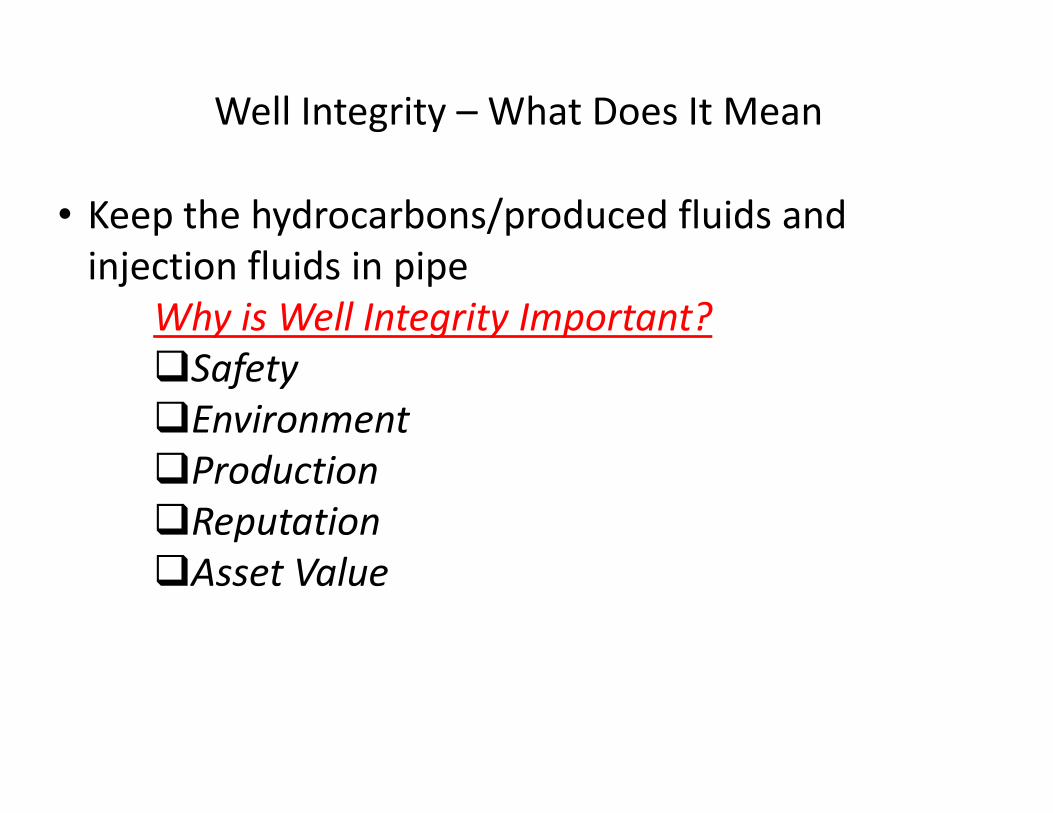
Natural Gas Storage in U.S.
Three main types of gas storage formations with ~ 400 active facilities(~ 17,500 storage wells) in
U.S. with ~ 80% of wells completed in 1980s or earlier
• Depleted oil and gas reservoirs – most common type (~ 80%). Well characterized and
typically contain some “cushion gas” from production phase
• Aquifers – account for ~ 10%. Although more expensive than depleted O&G fields, widely
distributed and located near population centers
• Salt caverns – account for ~ 10%. Formed in salt domes or salt beds (mostly located in Gulf
Coast ). Ability to perform several withdrawal and injection cycles/year
• Verification of inventory – how much gas can be stored as a function of pressure and
sometimes time. For depleted gas reservoirs, establish a top pressure above discovery for
storage, while aquifer storage requires gas injection above initial value to displace the water
when creating the gas reservoir
• Retention against migration – monitoring system to verify where the gas is residing and
ensure that losses are not occurring
• Assurance of Deliverability – ability to develop and maintain a specified gas deliverability
rate. Generally keyed to reservoir pressure and inventory; approx. 5% decline/year in
deliverability (increase in horizontal wells and hydraulic fracturing)
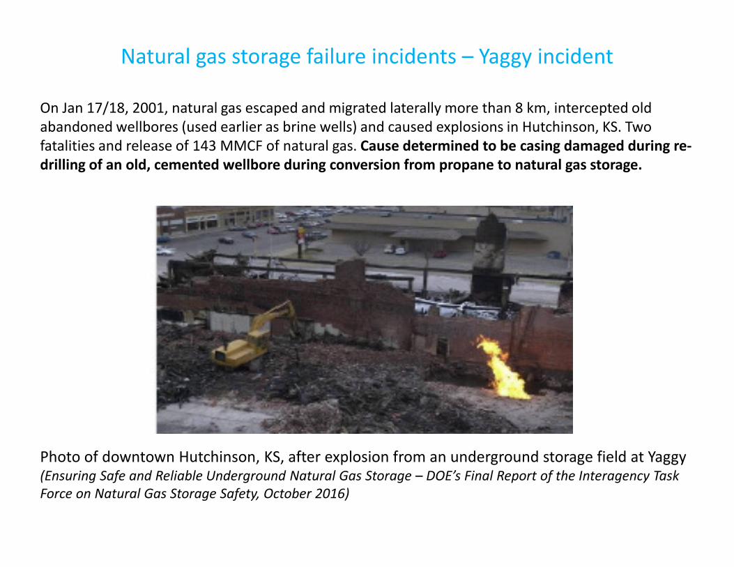
Natural gas storage failure incidents – Yaggy incident
Photo of downtown Hutchinson, KS, after explosion from an underground storage field at Yaggy(Ensuring Safe and Reliable Underground Natural Gas Storage – DOE’s Final Report of the Interagency Task
Force on Natural Gas Storage Safety, October 2016)
On Jan 17/18, 2001, natural gas escaped and migrated laterally more than 8 km, intercepted old
abandoned wellbores (used earlier as brine wells) and caused explosions in Hutchinson, KS. Two
fatalities and release of 143 MMCF of natural gas. Cause determined to be casing damaged during re-
drilling of an old, cemented wellbore during conversion from propane to natural gas storage.
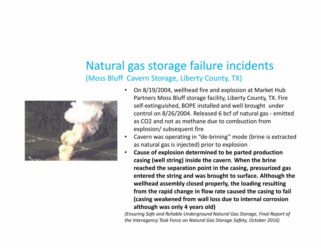
Natural gas storage failure incidents(Moss Bluff Cavern Storage, Liberty County, TX)
• On 8/19/2004, wellhead fire and explosion at Market Hub
Partners Moss Bluff storage facility, Liberty County, TX. Fire
self-extinguished, BOPE installed and well brought under
control on 8/26/2004. Released 6 bcf of natural gas - emitted
as CO2 and not as methane due to combustion from
explosion/ subsequent fire
• Cavern was operating in “de-brining” mode (brine is extracted
as natural gas is injected) prior to explosion
• Cause of explosion determined to be parted production
casing (well string) inside the cavern. When the brine
reached the separation point in the casing, pressurized gas
entered the string and was brought to surface. Although the
wellhead assembly closed properly, the loading resulting
from the rapid change in flow rate caused the casing to fail
(casing weakened from wall loss due to internal corrosion
although was only 4 years old)(Ensuring Safe and Reliable Underground Natural Gas Storage, Final Report of
the Interagency Task Force on Natural Gas Storage Safety, October 2016)
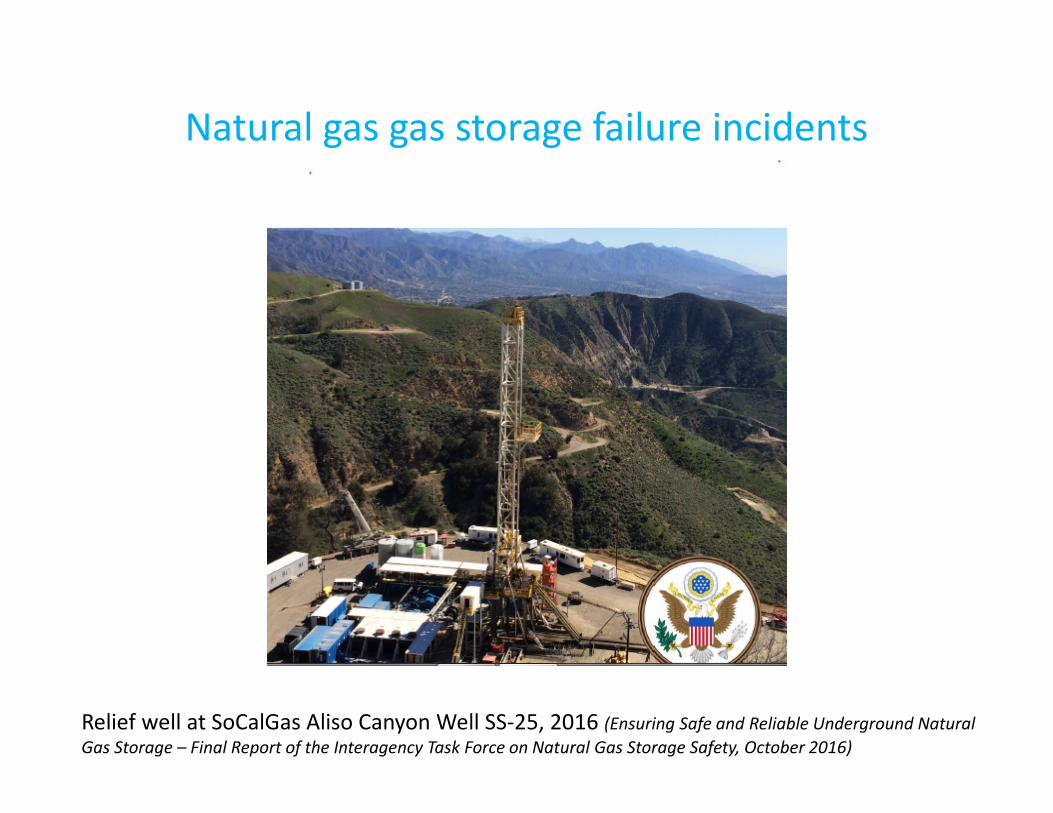
Natural gas gas storage failure incidents
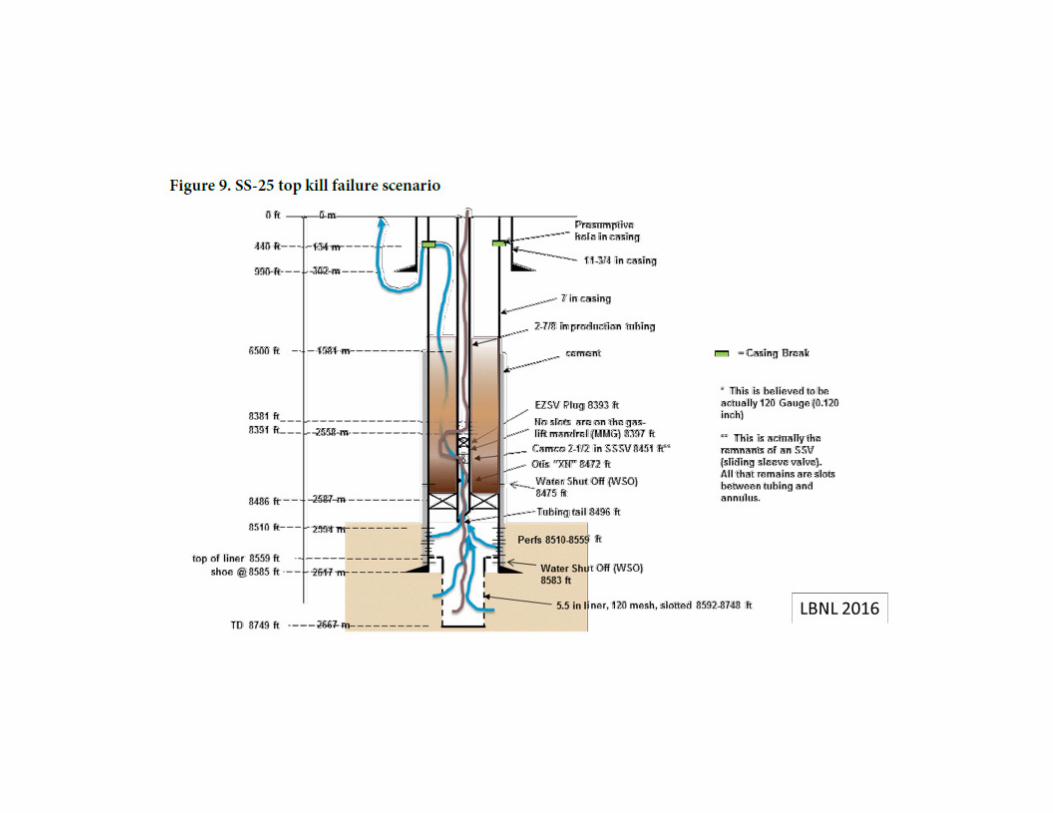
Relief well at SoCalGas Aliso Canyon Well SS-25, 2016 (Ensuring Safe and Reliable Underground Natural
Gas Storage – Final Report of the Interagency Task Force on Natural Gas Storage Safety, October 2016)
Aliso Canyon Incident
• On October 23, 2015 the largest methane leak in U.S. (estimated 4.62 bcf occurred at
SoCalGas Well SS-25 in Aliso Canyon Gas Storage Facility, LA County, CA. Suspected leak at
440’ in 7”casing (un-cemented upper part). Repeated top kill attempts failed. Drilled relief
well - well cemented and sealed on February 17, 2016
• Aliso Canyon facility has 115 storage injection wells with spud ages ranging from 1939 to
2014 with a total storage capacity of 86 bcf
• Well SS-25 originally drilled and completed as a producer in April 1954, sidetracked at
3,900’ (hole problems) and completed at ~ 8,950’ (sandstone) as a gas producer. Converted
to gas storage in May 1973. It was operated in natural gas pressure cycling through both
casing (un-cemented in critical upper sections) and tubing, providing only a single
protection barrier
• Many of the original wells had downhole safety valves (DHSVs) for pressure control. Later
the DHSVs were removed and not replaced, or replaced with subsurface sliding sleeve
valves (SSVs) to permit well maintenance and fluid circulation between tubing and tubing-
casing annulus (no DHSVs installed in wells drilled since 1980/reliability concerns). Wells
are considered capable of casing production if SSVs in tubing allowed gas flow to casing or
had no tubing
• Well SS-25 was monitored for gas leaks, annually in recent years, and sporadically or
biannually in earlier years. Also, no record of corrosion logs to verify metal loss
Barrier Elements and Philosophy
(Norsok D-010 and API Standard 65-2)
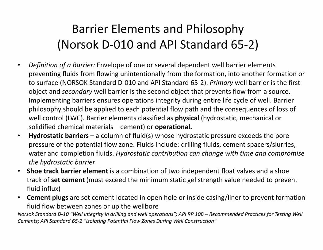
• Definition of a Barrier: Envelope of one or several dependent well barrier elements
preventing fluids from flowing unintentionally from the formation, into another formation or
to surface (NORSOK Standard D-010 and API Standard 65-2). Primary well barrier is the first
object and secondary well barrier is the second object that prevents flow from a source.
Implementing barriers ensures operations integrity during entire life cycle of well. Barrier
philosophy should be applied to each potential flow path and the consequences of loss of
well control (LWC). Barrier elements classified as physical (hydrostatic, mechanical or
solidified chemical materials – cement) or operational.
• Hydrostatic barriers – a column of fluid(s) whose hydrostatic pressure exceeds the pore
pressure of the potential flow zone. Fluids include: drilling fluids, cement spacers/slurries,
water and completion fluids. Hydrostatic contribution can change with time and compromise
the hydrostatic barrier
• Shoe track barrier element is a combination of two independent float valves and a shoe
track of set cement (must exceed the minimum static gel strength value needed to prevent
fluid influx)
• Cement plugs are set cement located in open hole or inside casing/liner to prevent formation
fluid flow between zones or up the wellboreNorsok Standard D-10 “Well integrity in drilling and well operations”; API RP 10B – Recommended Practices for Testing Well
Cements; API Standard 65-2 “Isolating Potential Flow Zones During Well Construction”
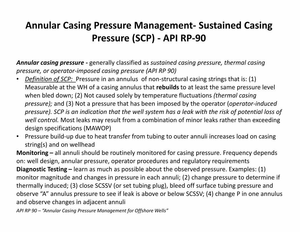
Annular Casing Pressure Management- Sustained Casing
Pressure (SCP) - API RP-90
Annular casing pressure - generally classified as sustained casing pressure, thermal casing
pressure, or operator-imposed casing pressure (API RP 90)
• Definition of SCP: Pressure in an annulus of non-structural casing strings that is: (1)
Measurable at the WH of a casing annulus that rebuilds to at least the same pressure level
when bled down; (2) Not caused solely by temperature fluctuations (thermal casing
pressure); and (3) Not a pressure that has been imposed by the operator (operator-induced
pressure). SCP is an indication that the well system has a leak with the risk of potential loss of
well control. Most leaks may result from a combination of minor leaks rather than exceeding
design specifications (MAWOP)
• Pressure build-up due to heat transfer from tubing to outer annuli increases load on casing
string(s) and on wellhead
Monitoring – all annuli should be routinely monitored for casing pressure. Frequency depends
on: well design, annular pressure, operator procedures and regulatory requirements
Diagnostic Testing – learn as much as possible about the observed pressure. Examples: (1)
monitor magnitude and changes in pressure in each annuli; (2) change pressure to determine if
thermally induced; (3) close SCSSV (or set tubing plug), bleed off surface tubing pressure and
observe “A” annulus pressure to see if leak is above or below SCSSV; (4) change P in one annulus
and observe changes in adjacent annuli
API RP 90 – “Annular Casing Pressure Management for Offshore Wells”
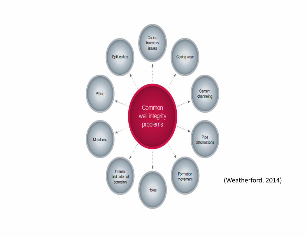
(Weatherford, 2014)
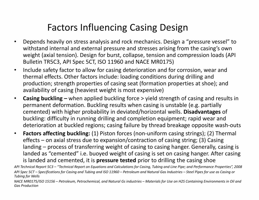
Factors Influencing Casing Design
• Depends heavily on stress analysis and rock mechanics. Design a “pressure vessel” to withstand internal and external pressure and stresses arising from the casing’s own weight (axial tension). Design for burst, collapse, tension and compression loads (API Bulletin TR5C3, API Spec 5CT, ISO 11960 and NACE MR0175)
• Include safety factor to allow for casing deterioration and for corrosion, wear and thermal effects. Other factors include: loading conditions during drilling and production; strength properties of casing seat (formation properties at shoe); and availability of casing (heaviest weight is most expensive)
• Casing buckling – when applied buckling force > yield strength of casing and results in permanent deformation. Buckling results when casing is unstable (e.g. partially cemented) with higher probability in deviated/horizontal wells. Disadvantages of buckling: difficulty in running drilling and completion equipment; rapid wear and deterioration at buckled regions; casing failure by thread breakage opposite wash-outs
• Factors affecting buckling: (1) Piston forces (non-uniform casing strings); (2) Thermal effects – on axial stress due to expansion/contraction of casing string; (3) Casing landing – process of transferring weight of casing to casing hanger. Generally, casing is landed as “cemented” i.e. buoyed weight of casing is set on casing hanger. After casing is landed and cemented, it is pressure tested prior to drilling the casing shoe
API Technical Report 5C3 – “Technical Report on Equations and Calculations for Casing, Tubing and Line Pipe; and Performance Properties”, 2008
API Spec 5CT – Specifications for Casing and Tubing and ISO 11960 – Petroleum and Natural Gas Industries – Steel Pipes for use as Casing or Tubing for Wells
NACE MR0175/ISO 15156 – Petroleum, Petrochemical, and Natural Gs industries – Materials for Use on H2S Containing Environments in Oil and Gas Production
Casing Design Considerations for Deviated/Horizontal Wells
Casing design factors for deviated/horizontal wells: Apply general casing design to
directional wells by converting measured depths (MD) to true vertical depths (TVD). For
directional wells, collapse pressure must be calculated using TVD only
• Bending forces arise in deviated/horizontal wells or in wells with severe dog-leg
problems where upper section is in tension and lower section is in compression
• Torque and Drag force is generated when running/pulling pipe in deviated wells due to
friction between pipe and hole or casing. Use computer models to generate the max.
Torque vs Running Depth and Drag Force vs Horizontal Distance graphs (critical in
selecting the torque rating of your casing and connection in casing design)
• Pipe wear due to running wireline tools and drill string assembly is extremely
detrimental in deviated/dog-legged holes (loading included in SF). Ensure the burst
resistance of casing is always > the highest expected internal pressure (to compensate
for reduction in wall thickness)
• Formation subsidence results in a non-uniform load especially with a poor cement job
(collapse rating may be reduced by 75%). Increase SF to 2.0
• Perforation intensity – PI > 4 SPF may reduce collapse resistance by 10-60%
Design Considerations for Fracture-Treating Down Casing
Strings
A casing string under fracturing conditions experiences large increase in
internal pressure and decrease in temperature caused by the fracturing fluids
(similar to that experienced by tubing held by a fixed packer). These forces can
be attributed to these four effects: (1) Piston effect – due to pressure changes
inside the casing or in the annulus. Could arise when an OH completion is
being fractured through casing set above it or when casing is not adequately
cemented; (2) Buckling effect – occurs when pipe tries to buckle due to larger
pressure inside the pipe than outside the pipe (minimal in casing fracturing);
(3) Ballooning effect – occurs when pressure differential from inside of casing
tries to balloon or swell the casing, creating a shortening effect that causes
tensile forces (critical during casing-fracturing operations); (4) Temperature
effect – Not due to pressure changes but function only of temperature
changes as hole is cooled down by fracture fluids
Brief Overview of State-of-Art Casing Design
Software
• Drilling in environments such as: high pressure/high temperature -HP/HT, deep/ultra-deep,
steam-assisted gravity drainage (SAGD), extended-reach (ERD and ultra-ERD), arctic, shale
gas/oil hydraulic fracturing and salt zone drilling result in complex loading conditions
• Most widely used industry software today is StressCheck and WellCAT with integrated
modules: (1) Casing Design applications: comprehensive casing design and analysis;
installation and service loads; buckling stability and post-buckling analysis; and connection
strength envelope safety factors; (2) Tubing Design applications: comprehensive tubing
design and analysis; installation and service loads; mechanically, hydrostatically and
hydraulically setting mechanisms; packer setting sequence; tubing movement, dual
completions; multiple packer completion configurations, CRA (corrosion and erosion
resistant alloy) tubular, and yield anisotropy, and packer envelope load check; (3) Drill
Design module simulates flow and heat transfer during drilling operations; (4) Prod Design
module simulates fluid and heat transfer during completion, production, stimulation, testing
and well-servicing operations; and (5) Multistring Design module predicts pressure and
volume changes caused by trapped annular pressure when well system heats up due to
production or injection of hot fluids. It determines the movement that occurs to the
wellhead during the life of the well
• WellCAT software by combining drilling, production thermal flow simulator modules, casing
and tubing stress analysis modules, and multistring load analysis module allows the
simulation of entire well history of events from drilling and production operations
(
Cementing Failures
Well Cementing is simply the displacement by cement of the drilling fluid in the well
casing-open hole annulus, so why are there failures? (Kirksey, 2013)
• Execution:
- Poor selection; inappropriate supplier
- Equipment failure: Maintenance, catastrophic, rig related
- People failure: Training and competency, human error, lack of planning,
QA/QC process
• Design Failures (Not so simple):
- Incomplete mud removal
- Flow after placement
- Inappropriate slurry
(API Spec 10A, API Standard 65-2, API 1171, ISO 16530-2)
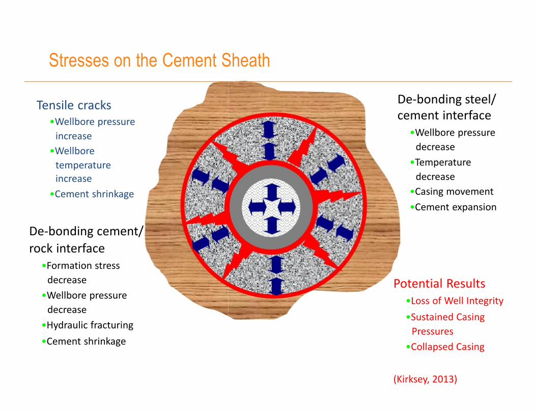
Stresses on the Cement Sheath
Tensile cracks
•Wellbore pressure
increase
•Wellbore
temperature
increase
•Cement shrinkage
De-bonding cement/
rock interface
•Formation stress
decrease
•Wellbore pressure
decrease
•Hydraulic fracturing
•Cement shrinkage
De-bonding steel/
cement interface
•Wellbore pressure
decrease
•Temperature
decrease
•Casing movement
•Cement expansion
Potential Results
•Loss of Well Integrity
•Sustained Casing
Pressures
•Collapsed Casing
(Kirksey, 2013)
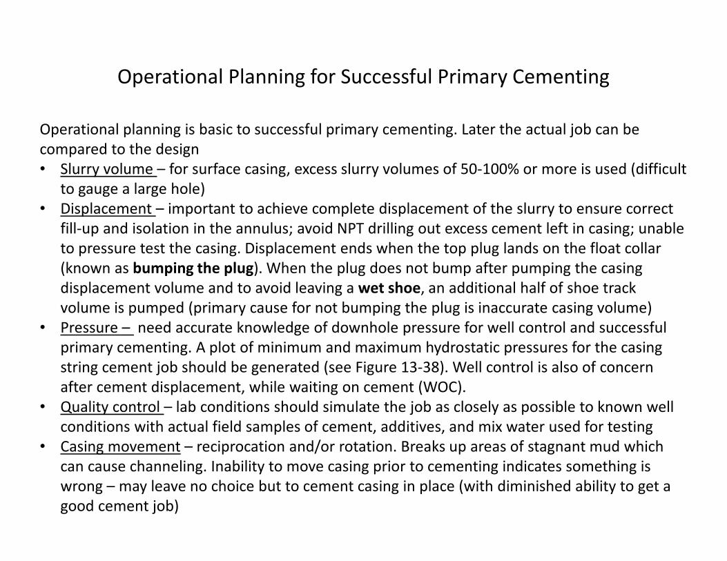
Operational Planning for Successful Primary Cementing
Operational planning is basic to successful primary cementing. Later the actual job can be
compared to the design
• Slurry volume – for surface casing, excess slurry volumes of 50-100% or more is used (difficult
to gauge a large hole)
• Displacement – important to achieve complete displacement of the slurry to ensure correct
fill-up and isolation in the annulus; avoid NPT drilling out excess cement left in casing; unable
to pressure test the casing. Displacement ends when the top plug lands on the float collar
(known as bumping the plug). When the plug does not bump after pumping the casing
displacement volume and to avoid leaving a wet shoe, an additional half of shoe track
volume is pumped (primary cause for not bumping the plug is inaccurate casing volume)
• Pressure – need accurate knowledge of downhole pressure for well control and successful
primary cementing. A plot of minimum and maximum hydrostatic pressures for the casing
string cement job should be generated (see Figure 13-38). Well control is also of concern
after cement displacement, while waiting on cement (WOC).
• Quality control – lab conditions should simulate the job as closely as possible to known well
conditions with actual field samples of cement, additives, and mix water used for testing
• Casing movement – reciprocation and/or rotation. Breaks up areas of stagnant mud which
can cause channeling. Inability to move casing prior to cementing indicates something is
wrong – may leave no choice but to cement casing in place (with diminished ability to get a
good cement job)
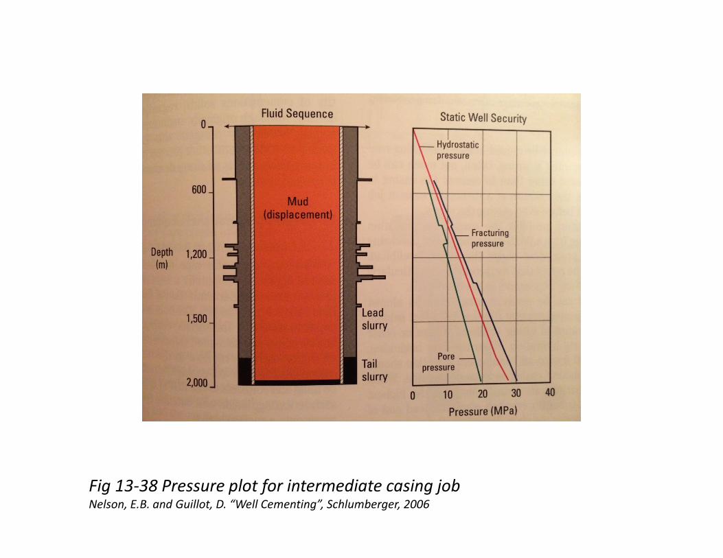
Fig 13-38 Pressure plot for intermediate casing jobNelson, E.B. and Guillot, D. “Well Cementing”, Schlumberger, 2006
Operational Planning for Successful Primary Cementing (Contd)
Cement job monitoring – pressure, slurry rate, density, and integrated volume must be known in
real time along with the correct volumes and densities of pre-flushes, spacers, and cement
slurry. Ensure pressure-monitoring equipment is working properly (see output in Fig 13-40)
Hole condition – review drilling reports to identify problems such as hole washouts, lost
circulation and tight spots and address in design. Run caliper logs on most jobs. Condition the
hole and optimize mud properties prior to the cement job so that the modified mud is able to
displace the gelled mud left over from displacement process
Temperature – knowledge of bottom hole circulating temperature (BHCT) is vital, since slurry
pumping time is a direct function of the BHCT. Temperature also affects cement and mud
properties – flow regimes, U-tubing effect and friction pressures. Temperature simulators are
important to determine BHCT and strength development time. Pre-job lab testing should
consider time of job (summer/winter) and cement and mix-water temps that differ significantly
from 800 F – so that WOC is not too long in winter and too short in summer
Buckling prevention steps: (1) Cement up to a Neutral Point where no buckling potential exists;
(2) Pull the casing which puts extra tension on the casing while landing; (3) Maintain internal
pressure on the casing whilst the cement sets; (4) use centralizers to reduce clearance between
the casing and the hole wall
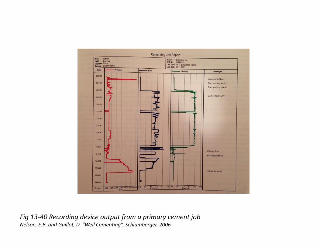
Fig 13-40 Recording device output from a primary cement jobNelson, E.B. and Guillot, D. “Well Cementing”, Schlumberger, 2006
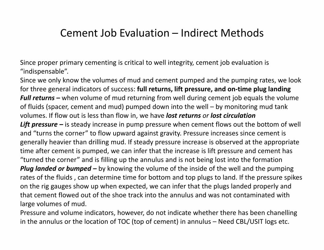
Cement Job Evaluation – Indirect Methods
Since proper primary cementing is critical to well integrity, cement job evaluation is
“indispensable”.
Since we only know the volumes of mud and cement pumped and the pumping rates, we look
for three general indicators of success: full returns, lift pressure, and on-time plug landing
Full returns – when volume of mud returning from well during cement job equals the volume
of fluids (spacer, cement and mud) pumped down into the well – by monitoring mud tank
volumes. If flow out is less than flow in, we have lost returns or lost circulation
Lift pressure – is steady increase in pump pressure when cement flows out the bottom of well
and “turns the corner” to flow upward against gravity. Pressure increases since cement is
generally heavier than drilling mud. If steady pressure increase is observed at the appropriate
time after cement is pumped, we can infer that the increase is lift pressure and cement has
“turned the corner” and is filling up the annulus and is not being lost into the formation
Plug landed or bumped – by knowing the volume of the inside of the well and the pumping
rates of the fluids , can determine time for bottom and top plugs to land. If the pressure spikes
on the rig gauges show up when expected, we can infer that the plugs landed properly and
that cement flowed out of the shoe track into the annulus and was not contaminated with
large volumes of mud.
Pressure and volume indicators, however, do not indicate whether there has been chanelling
in the annulus or the location of TOC (top of cement) in annulus – Need CBL/USIT logs etc.
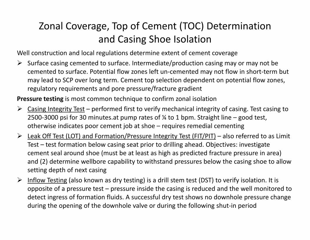
Zonal Coverage, Top of Cement (TOC) Determination
and Casing Shoe Isolation
Well construction and local regulations determine extent of cement coverage
� Surface casing cemented to surface. Intermediate/production casing may or may not be
cemented to surface. Potential flow zones left un-cemented may not flow in short-term but
may lead to SCP over long term. Cement top selection dependent on potential flow zones,
regulatory requirements and pore pressure/fracture gradient
Pressure testing is most common technique to confirm zonal isolation
� Casing Integrity Test – performed first to verify mechanical integrity of casing. Test casing to
2500-3000 psi for 30 minutes.at pump rates of ¼ to 1 bpm. Straight line – good test,
otherwise indicates poor cement job at shoe – requires remedial cementing
� Leak Off Test (LOT) and Formation/Pressure Integrity Test (FIT/PIT) – also referred to as Limit
Test – test formation below casing seat prior to drilling ahead. Objectives: investigate
cement seal around shoe (must be at least as high as predicted fracture pressure in area)
and (2) determine wellbore capability to withstand pressures below the casing shoe to allow
setting depth of next casing
� Inflow Testing (also known as dry testing) is a drill stem test (DST) to verify isolation. It is
opposite of a pressure test – pressure inside the casing is reduced and the well monitored to
detect ingress of formation fluids. A successful dry test shows no downhole pressure change
during the opening of the downhole valve or during the following shut-in period
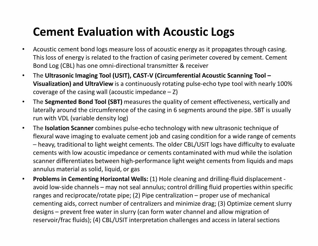
Cement Evaluation with Acoustic Logs
• Acoustic cement bond logs measure loss of acoustic energy as it propagates through casing.
This loss of energy is related to the fraction of casing perimeter covered by cement. Cement
Bond Log (CBL) has one omni-directional transmitter & receiver
• The Ultrasonic Imaging Tool (USIT), CAST-V (Circumferential Acoustic Scanning Tool –
Visualization) and UltraView is a continuously rotating pulse-echo type tool with nearly 100%
coverage of the casing wall (acoustic impedance – Z)
• The Segmented Bond Tool (SBT) measures the quality of cement effectiveness, vertically and
laterally around the circumference of the casing in 6 segments around the pipe. SBT is usually
run with VDL (variable density log)
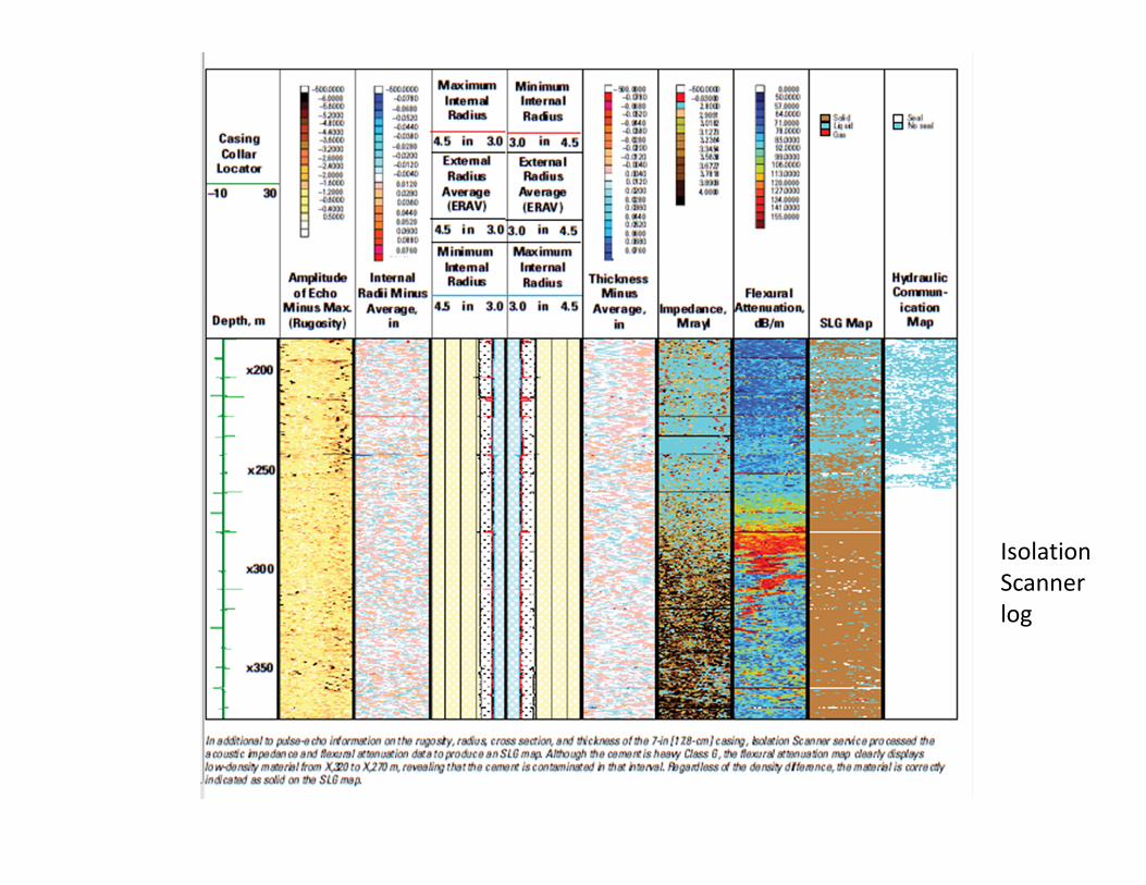
• The Isolation Scanner combines pulse-echo technology with new ultrasonic technique of
flexural wave imaging to evaluate cement job and casing condition for a wide range of cements
– heavy, traditional to light weight cements. The older CBL/USIT logs have difficulty to evaluate
cements with low acoustic impedance or cements contaminated with mud while the isolation
scanner differentiates between high-performance light weight cements from liquids and maps
annulus material as solid, liquid, or gas
• Problems in Cementing Horizontal Wells: (1) Hole cleaning and drilling-fluid displacement -
avoid low-side channels – may not seal annulus; control drilling fluid properties within specific
ranges and reciprocate/rotate pipe; (2) Pipe centralization – proper use of mechanical
cementing aids, correct number of centralizers and minimize drag; (3) Optimize cement slurry
designs – prevent free water in slurry (can form water channel and allow migration of
reservoir/frac fluids); (4) CBL/USIT interpretation challenges and access in lateral sections
Isolation
Scanner
log
Cementing - Gas Storage Wells
• Gas storage wells generally have a long life-cycle (40 to 60 years) and are often close to urban
areas. A successful primary cement job and zonal isolation is critical for long-term well
integrity of gas storage wells.
• Cement sheath damage can occur during drilling, production and stimulation. Fluctuations in
pressure and temperature (during the injection and withdrawal cycles), induces different
stresses on set cement in the annulus, with loss of well integrity either by de-bonding or
cracking, while use of conventional cements may lead to tension failure. Loss of well integrity
may result in sustained casing pressure (SCP), surface casing vent flow (SCVF), hydrocarbon
cross-flow or migration of hydrocarbons to the surface
• Flexible cements and self-healing cements (with mechanical properties matched to the
changing downhole stress environment) have been successfully used to cement gas storage
wells in U.S., Germany, China and Italy. Self-healing cements have also been successful in
remediating gas migration (leading to SCP and SCVF) from shallow gas formations to the
surface from cement sheath damage and de-bonding, in a heavy oil project in Canada.
• The flexible cements are designed to provide the primary barrier against gas migration
(opposite the reservoir), while the self-healing cements provide a secondary barrier against
leaks, by swelling to close gaps and flow-paths when it comes into contact with
hydrocarbons. The self-healing cement can be strategically placed at any depth, in any string
of the well, to obtain an effective long-term seal, and can be used to re-seal whenever
annular integrity is compromised.
• Internal MIT/APM – Pressure test and annular pressure monitoring
• External MIT – confirm all fluids contained within wellbore and no leaks/flow behind casing –
Noise logs, Temperature surveys, USIT/SBT-VDL/CAST-V, Isolation Scanner and Oxygen
Activation/Water Flow Log, Radioactive Tracer, Borax Pulsed Neutron Log, Carbon Oxygen
• Pressure tests at casing shoe (FIT/LOT/CIT) to verify zonal isolation
• Multi-finger caliper (MIT) surveys and magnetic thickness tools (MTT) to assess both internal
and external condition of the tubular from corrosion and/or erosion impacts
• Ultrasonic leak detection tools – can detect very small leaks through multiple strings (since
ultra-sound is not attenuated by gas, liquid, or steel). Can be run on wireline or slick-line in
memory mode (coupled with caliper in a single run and in high-pressure wells (where it is
difficult to maintain a seal)
• Noise logs limitations included: one hydrophone or receiver with limited frequency range;
stationary readings; inability to detect small leaks and through multiple strings; unwanted
“road noise” while tool is moving. Newer techniques ANT (Array Noise Tool) and ALFA (Acoustic
Leak Flow Analyser) are available that measure acoustic data in the range of 8 Hz to 60,000 kHz
with very high frequency resolution with continuous logging
Note: Historically noise logs and temperature surveys used for leak detection in gas storage fields.
During conversion at Aliso Canyon for gas storage in the 1970s, a quarter of the wells logged with
CBL/Neutron logs. Pre-2015 leak event, majority of wells not evaluated for cement integrity
Wellbore/Mechanical Integrity Methods
Well Integrity for Gas Storage WellsRecommendations for Maintaining Well Integrity of Gas Storage Wells
� Operator must maintain well control at all times. Each well must have either a subsurface (SCSSSV)
or wellhead surface safety valve system and the safety systems must be tested every 180 days
(pros and cons/reliability issues with DHSV/ESVs)
� Each newly drilled well must have a minimum 2-barrier well design and be equipped with tubing
and packer. Each well must demonstrate successful well integrity (MITIA) at least every 4 to 5
years. Higher testing frequency may be required by regulatory agencies depending upon well
design and risk assessment for potential loss of well integrity (1-barrier or 2-barrier systems, age of
wells/ converted wells, and reservoir conditions)
� Run baseline casing inspection logs and external mechanical integrity logs (temp/noise/CBL etc.) in
each new well (and at time of conversion) and then at least every 4-5 years in conjunction with
MITIA. Frequency may be increased by regulator depending upon risk assessment/condition of
tubular
� Record tubing and annuli pressure continuously and submit monthly data to the agency along with
production/injection rate data. In the event of pressure communication or loss of wellbore
integrity, well must be shut-in and agency notified, pending diagnostics
� Offset production/injection wells should be monitored for flow or pressure changes/anomalies and
plugged wells inspected for lateral gas migration. The AOR can be increased from a ¼ mile to up to
2 miles depending upon elevated risk factors. Selected key observation wells can be monitored for
gas presence above the storage reservoir and GR-Neutron logs can be run to confirm no gas
accumulation outside the storage zone
� If wells are to be hydraulically fractured to increase deliverability, test casing to 110 to 115% of
anticipated treatment pressure. If it fails, repair or use fracturing string