Well Stimulation - courses.oilprocessing.net
43
Basic Applied Production Technology ___________________________________________________________________________________ TriStar M. East Page 1 of 43 Well Stimulation
Transcript of Well Stimulation - courses.oilprocessing.net
Basic Applied Production Technology ___________________________________________________________________________________
TriStar M. East Page 1 of 43
Well Stimulation

Basic Applied Production Technology ___________________________________________________________________________________
TriStar M. East Page 2 of 43
(A)
Acidizing & Other Matrix Treatments
Basic Applied Production Technology ___________________________________________________________________________________
TriStar M. East Page 3 of 43
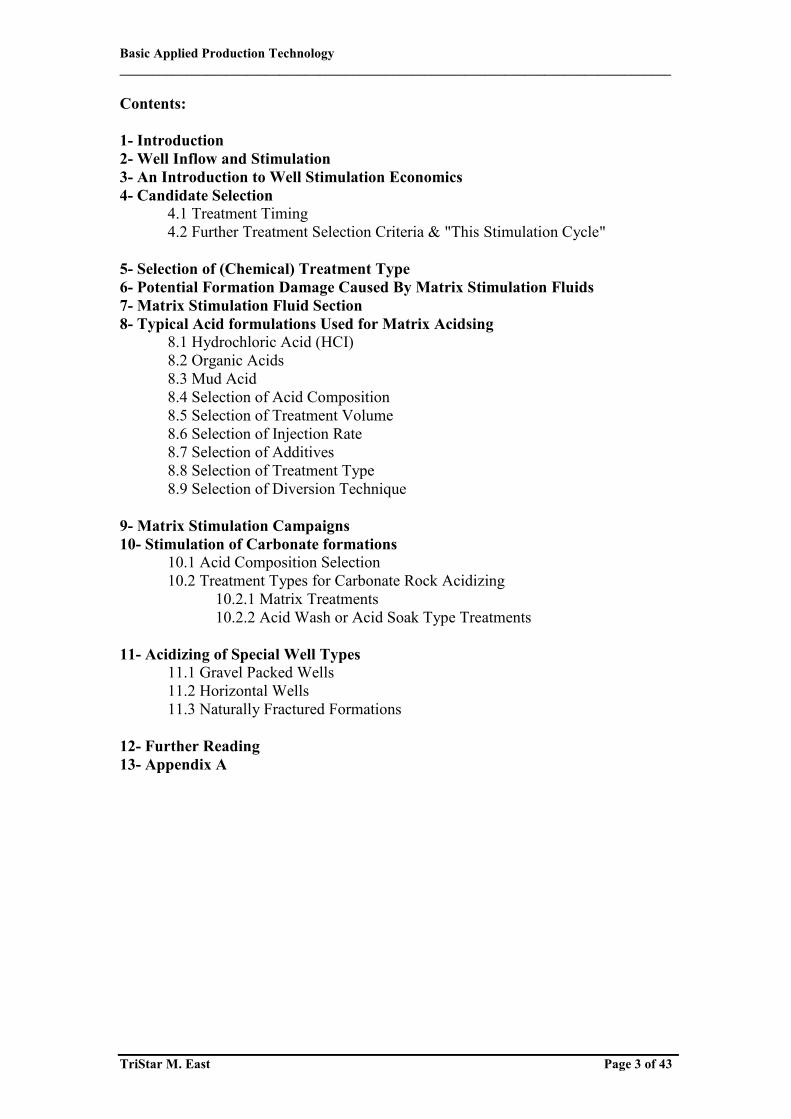
Contents: 1- Introduction 2- Well Inflow and Stimulation 3- An Introduction to Well Stimulation Economics 4- Candidate Selection
4.1 Treatment Timing 4.2 Further Treatment Selection Criteria & "This Stimulation Cycle"
5- Selection of (Chemical) Treatment Type 6- Potential Formation Damage Caused By Matrix Stimulation Fluids 7- Matrix Stimulation Fluid Section 8- Typical Acid formulations Used for Matrix Acidsing 8.1 Hydrochloric Acid (HCI) 8.2 Organic Acids 8.3 Mud Acid 8.4 Selection of Acid Composition 8.5 Selection of Treatment Volume 8.6 Selection of Injection Rate 8.7 Selection of Additives 8.8 Selection of Treatment Type 8.9 Selection of Diversion Technique 9- Matrix Stimulation Campaigns 10- Stimulation of Carbonate formations
10.1 Acid Composition Selection 10.2 Treatment Types for Carbonate Rock Acidizing
10.2.1 Matrix Treatments 10.2.2 Acid Wash or Acid Soak Type Treatments
11- Acidizing of Special Well Types 11.1 Gravel Packed Wells 11.2 Horizontal Wells 11.3 Naturally Fractured Formations 12- Further Reading 13- Appendix A

Basic Applied Production Technology ___________________________________________________________________________________
TriStar M. East Page 4 of 43
Learning Objectives: Having worked through this chapter the student will be able to:
Explain the importance of matrix stimulation in Production Engineering.
Identify and contrast the application areas of the various types of matrix
stimulation techniques.
Generically list primary chemical reactions sandstone and carbonate acidizing.
Explain the potential negative impacts of “matrix stimulation “and identify
migration strategies
Select acid formulation on the basis of source of formation damage and rock
composition
Identify and discuss the role of acid additives.
Discuss placement and diversion techniques.
Design a matrix acidizing treatment (acid volume and injection rate)
Basic Applied Production Technology ___________________________________________________________________________________
TriStar M. East Page 5 of 43
1- Introduction
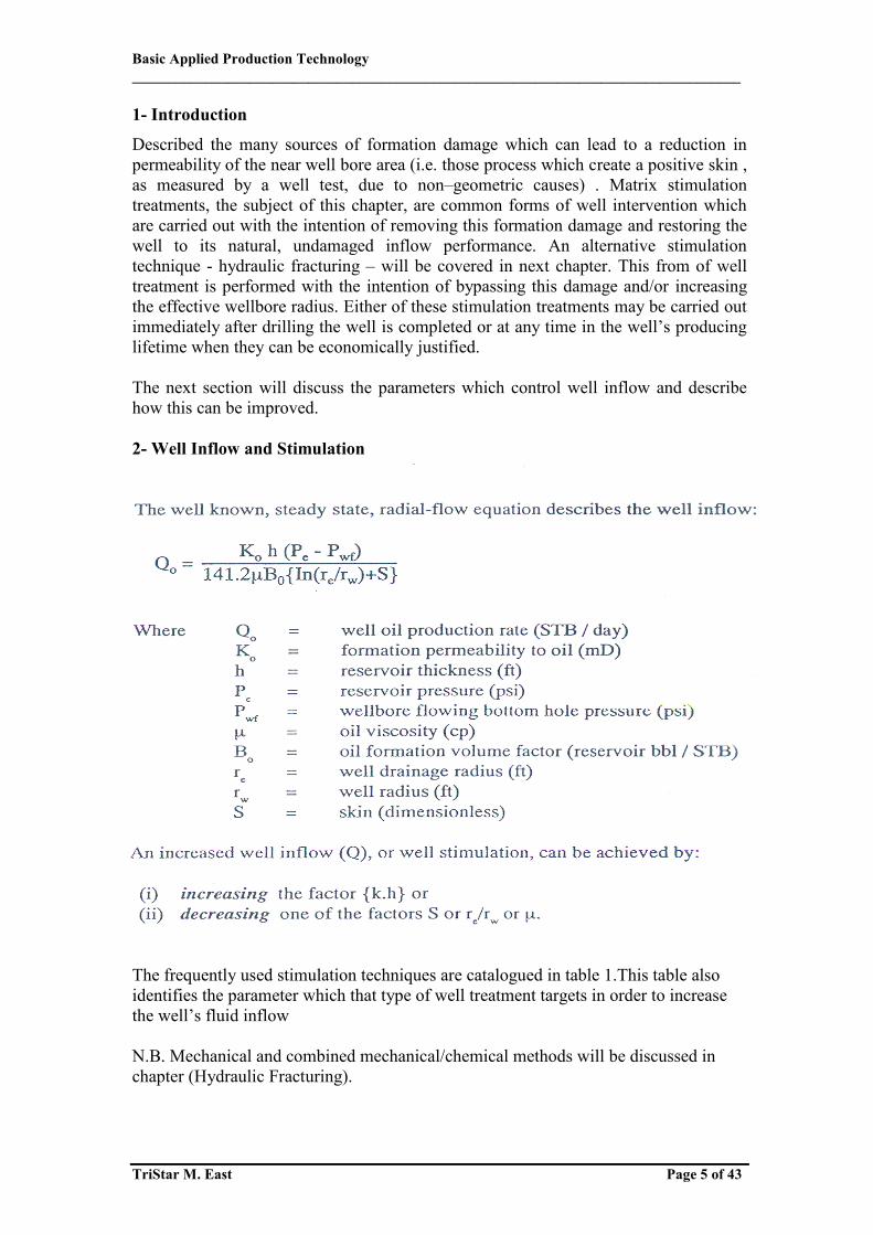
Described the many sources of formation damage which can lead to a reduction in permeability of the near well bore area (i.e. those process which create a positive skin , as measured by a well test, due to non–geometric causes) . Matrix stimulation treatments, the subject of this chapter, are common forms of well intervention which are carried out with the intention of removing this formation damage and restoring the well to its natural, undamaged inflow performance. An alternative stimulation technique - hydraulic fracturing – will be covered in next chapter. This from of well treatment is performed with the intention of bypassing this damage and/or increasing the effective wellbore radius. Either of these stimulation treatments may be carried out immediately after drilling the well is completed or at any time in the well’s producing lifetime when they can be economically justified. The next section will discuss the parameters which control well inflow and describe how this can be improved. 2- Well Inflow and Stimulation The frequently used stimulation techniques are catalogued in table 1.This table also identifies the parameter which that type of well treatment targets in order to increase the well’s fluid inflow N.B. Mechanical and combined mechanical/chemical methods will be discussed in chapter (Hydraulic Fracturing).
Basic Applied Production Technology ___________________________________________________________________________________
TriStar M. East Page 6 of 43
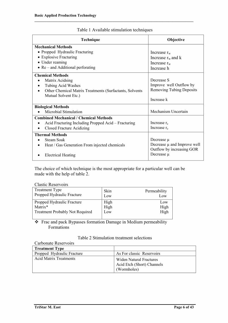
Table 1 Available stimulation techniques
Technique Objective
Mechanical Methods Propped Hydraulic Fracturing Explosive Fracturing Under reaming Re – and Additional perforating
Increase rw Increase rw and k Increase rw Increase h
Chemical Methods Matrix Acidsing Tubing Acid Washes Other Chemical Matrix Treatments (Surfactants, Solvents
Mutual Solvent Etc.)
Decrease S Improve well Outflow by Removing Tubing Deposits Increase k
Biological Methods Microbial Stimulation
Mechanism Uncertain
Combined Mechanical / Chemical Methods Acid Fracturing Including Propped Acid – Fracturing Closed Fracture Acidizing
Increase re Increase re
Thermal Methods Steam Soak Heat / Gas Generation From injected chemicals Electrical Heating
Decrease µ Decrease µ and Improve well Outflow by increasing GOR Decrease µ
The choice of which technique is the most appropriate for a particular well can be made with the help of table 2. Clastic Reservoirs Treatment Type Propped Hydraulic Fracture
Skin Permeability Low Low
Propped Hydraulic Fracture Matrix* Treatment Probably Not Required
High Low High High Low High
Frac and pack Bypasses formation Damage in Medium permeability Formations
Table 2 Stimulation treatment selections
Carbonate Reservoirs Treatment Type Propped Hydraulic Fracture As For classic Reservoirs Acid Matrix Treatments Widen Natural Fractures
Acid Etch (Short) Channels (Wormholes)
Basic Applied Production Technology ___________________________________________________________________________________
TriStar M. East Page 7 of 43
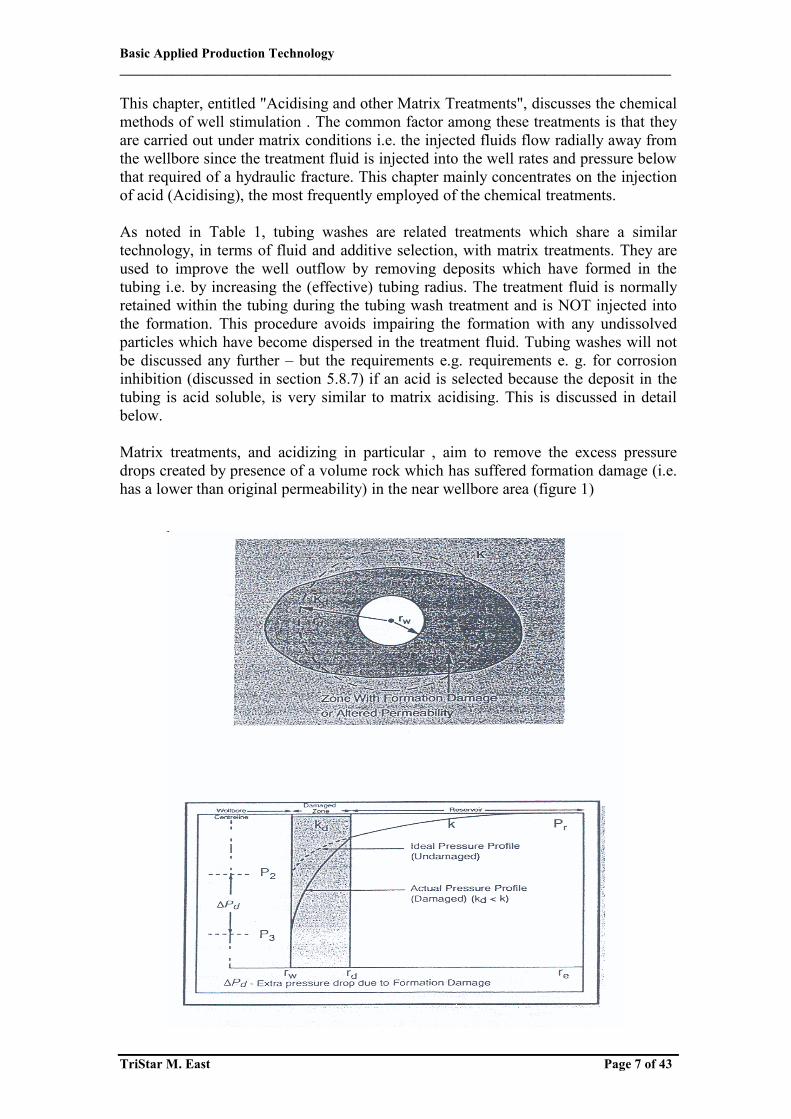
This chapter, entitled "Acidising and other Matrix Treatments", discusses the chemical methods of well stimulation . The common factor among these treatments is that they are carried out under matrix conditions i.e. the injected fluids flow radially away from the wellbore since the treatment fluid is injected into the well rates and pressure below that required of a hydraulic fracture. This chapter mainly concentrates on the injection of acid (Acidising), the most frequently employed of the chemical treatments. As noted in Table 1, tubing washes are related treatments which share a similar technology, in terms of fluid and additive selection, with matrix treatments. They are used to improve the well outflow by removing deposits which have formed in the tubing i.e. by increasing the (effective) tubing radius. The treatment fluid is normally retained within the tubing during the tubing wash treatment and is NOT injected into the formation. This procedure avoids impairing the formation with any undissolved particles which have become dispersed in the treatment fluid. Tubing washes will not be discussed any further – but the requirements e.g. requirements e. g. for corrosion inhibition (discussed in section 5.8.7) if an acid is selected because the deposit in the tubing is acid soluble, is very similar to matrix acidising. This is discussed in detail below. Matrix treatments, and acidizing in particular , aim to remove the excess pressure drops created by presence of a volume rock which has suffered formation damage (i.e. has a lower than original permeability) in the near wellbore area (figure 1)

Basic Applied Production Technology ___________________________________________________________________________________
TriStar M. East Page 8 of 43
The removal of this formation damage will restore the "natural" well productivity. The Hawkins formula: It's a convenient tool for analyzing the influence of varying levels and depths of formation damage. Matrix stimulation treatment increase well productivity by pumping a specially Formulated treatment fluid (frequently, but not always, an acid) which is designed to remove (normally dissolve) the formation damage. However, the keys to successful treatments are:
(1) the identification of a suitable candidate well , (2) the selection of the operational aspects of the treatment (3) the design of the operational aspects of the treatment
Such that the required economic criteria are successfully achieved. The next section of this chapter will discuss some simple, economic concepts which help identify where a simulation treatment could be economically viable. 3- An Introduction to Well Stimulation Economics Well stimulation is only justified when the net (discounted) monetary benefit of the resulting extra oil or gas production is greater than the cost of the stimulation treatment. Previous field experience from the stimulation of similar wells is often a good guide when predicting the excepted gain from the well stimulation treatment. Another , simple but approximate , method to estimate the potential benefits from a stimulation treatment is to use the that the production wells typically show a constant , long term , annual percentage decline in net , hydrocarbon production . This decline can be expressed in the form of a straight line when the logarithm of the net, hydrocarbon production is plotted against time (see figure 2)
Where
Basic Applied Production Technology ___________________________________________________________________________________
TriStar M. East Page 9 of 43
N. B. A straight with a steeper slope on this graph corresponds a greater, annual, Net hydrocarbon production decline rate the expected, net, hydrocarbon production decline rate. The expected, net hydrocarbon production gain from the stimulation treatment needs to be estimated as the first step in carrying out the economic evaluation. This can be estimated if:
1. The well’s skin value is known (equation 1) or 2. By use of the Hawkins formulas (equation 2) if the extent and depth of
formation damage are know or can be guessed. Field experience has shown that this gain in production will normally be followed by an increased, production decline rate. In time , the well’s production rate will of revert to its predicted , original (unstimulated ) value or even drop below this extrapolated lated value The latter occurs if the well’s reserves have undergone an accelerated depletion resulting from the increased well production following the well simulation. Thus an estimate of the length of time that the well stimulation treatment will increase the well production is also required. Remember that these prognoses must not only consider:
1) The well inflow i. e. whether the well has sufficient inflow capacity and remaining reserves
2) but also the well outflow capabilities (the tubing flow capacity ) , as well as 3) Whether the production facilities have sufficient capacity to process the extra
fluid volumes. The above or other techniques allow the net hydrocarbon production gain from stimulation to be estimated. These volumes should be reduced by the:
(i) appropriate discount rate (since hydrocarbon produced today is more valuable than later hydrocarbon production ) ,
(ii) hydrocarbon production lost while the well was taken off production to carry out the well stimulation treatment
(iii) Expected chance that the stimulation will be successful (this often lower than 100%)
The resulting increased revenue can be calculated from this discounted increase in net hydrocarbon production multiplied by the net revenue per unit of production (sales prices minus marginal operating expenditure). This has to be compared with the cost of the stimulation which should include the:
a) loss of income due to the well being shut in while the stimulation was being carried out . Items such as the reduced throughput in facilities while back produced stimulation fluids are being treated may also have to be include
b) cost of mobilization and rental of equipment ( pumps , tank , etc .) and
personnel employed for the well stimulation treatment .

Basic Applied Production Technology ___________________________________________________________________________________
TriStar M. East Page 10 of 43
c) cost of consumable e.g. chemicals etc. used for the well stimulation treatment This cost is related to the size of the stimulation treatment, while the earlier ones are related to the type of stimulation treatment chosen .
From the point of view of stimulation candidate well selection, the stimulation treatment yielding the highest prognosed (discounted) rate of return is the treatment which should be carried out first. Most production companies expect a very high rate of return from this type of well treatment, the well chosen etc. A somewhat simpler calculation method is to calculate the payback time i.e. the production time required for the increased, net hydrocarbon production to pay back the cost of the well stimulation treatment. The most profitable well stimulation candidate is the stimulation treatment yielding the most rapid pay back. This is the well treatment which should be carried out first. Most companies require pay back times of between 6and 12 months from this type of well treatment. N.B. These economic concepts are treated in greater detail in the economics module of this Petroleum Engineering course. 4- Candidate Selection The selection of stimulation candidates that potentially meet the economic screening criteria discussed in the previous section is the key to a successful stimulation campaign. This involves two stages:
(i) the identification and (accurate) quantification of those parameters which control the productivity of the specific well and
(ii) an analysis to determine whether the well stimulation treatment would actually improve the well production .
As mentioned earlier, it is important here to distinguish between well (inflow) productivity and well production. This is because an improvement in the well "inflow" performance (from the reservoir to the well) can have only a limited effect on the daily well production if the well "outflow" is limited by tubing / artificial lift / facilities restriction. The need to consider the flow path from the reservoir boundary to the production storage facilities as a complete production system (figure 3).

Basic Applied Production Technology ___________________________________________________________________________________
TriStar M. East Page 11 of 43
Table 3 Summaries typical values for the minimum requirements for a successful (matrix) stimulation treatment. The criteria in this table can be used for the preliminary screening of well stimulation candidates. These figures are based on experience from a number of fields, but may be modified to be more focused when studying specific fields
Table 3 Minimum Matrix Treatment Candidate well selection Criteria
Parameter Oil Reservoir Gas Reservoir Hydrocarbon Saturation Water Cut Permeability † Reservoir Pressure
>40% <30%
>20 mD* <70% depleted
>50% >200 bbls/MMscl**
>1 mD twice abandonment pressure
Production System 20% spare capacity Ø * higher value required for viscous oil production Ø lower value if several wells are manifolded together † wells with lower permeabilities are potential hydraulic fracturing candidates ** evaluate potential for well killing itself due to liquid loading in the tubing The above criteria evaluate whether the well has a sufficient minimum of:
(i) Remaining reserves to justify carrying out the remedial stimulation technique,
(ii) Well inflow productivity and (iii) Capacity in the facilities to process the extra fluid production
The well skin (S) is not mentioned in the table 3 criteria – this is because the skin can not be considered apart from the other parameters that control the well inflow {the reservoir permeability thickness (k.h) and the potential well drawdown (pe- pwf)}. Thus, a small reduction in skin value from a well with a large reservoir permeability thickness can yield a much larger production increase than removal of a high skin value from a well with a small reservoir permeability thickness. Alternatively, installation of an artificial lift method which allows an increased drawdown may be the
Basic Applied Production Technology ___________________________________________________________________________________
TriStar M. East Page 12 of 43
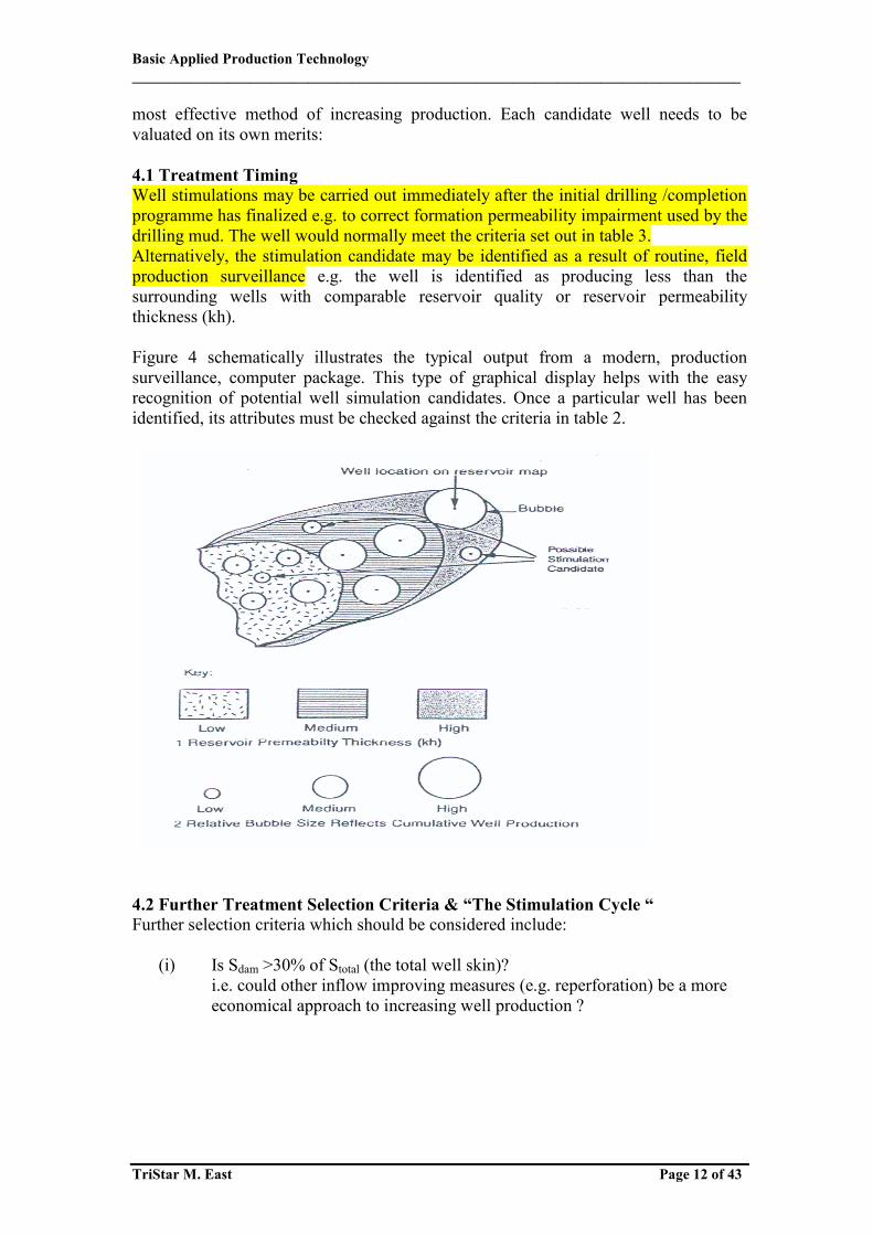
most effective method of increasing production. Each candidate well needs to be valuated on its own merits: 4.1 Treatment Timing Well stimulations may be carried out immediately after the initial drilling /completion programme has finalized e.g. to correct formation permeability impairment used by the drilling mud. The well would normally meet the criteria set out in table 3. Alternatively, the stimulation candidate may be identified as a result of routine, field production surveillance e.g. the well is identified as producing less than the surrounding wells with comparable reservoir quality or reservoir permeability thickness (kh). Figure 4 schematically illustrates the typical output from a modern, production surveillance, computer package. This type of graphical display helps with the easy recognition of potential well simulation candidates. Once a particular well has been identified, its attributes must be checked against the criteria in table 2. 4.2 Further Treatment Selection Criteria & “The Stimulation Cycle “ Further selection criteria which should be considered include:
(i) Is Sdam >30% of Stotal (the total well skin)? i.e. could other inflow improving measures (e.g. reperforation) be a more economical approach to increasing well production ?
Basic Applied Production Technology ___________________________________________________________________________________
TriStar M. East Page 13 of 43
Table 4 gives examples of poor well productivity, which can not be “Stimulated away “
Table 4 Stimulated Treatment Selection
Examples of Poor Well productivity that can not be: "stimulated away "
Gas Well with > 200 bbls liquid /MMscf Three phases production
Poor tubing Outflow
Gas well-high drawdown Oil well ->20bb/ft
non-Darcy (turbulence) effects
Oil wells > 5 bbl/day/ perf Partial penetration reservoir
Completion Geometrical Skin
(ii) Does the well show sand production?
Are sand control measures in place? (matrix stimulation treatments of gravel packed completions are treated).
(iii) Is the cause of formation damage greatly increases the chance of matrix
treatment success since a treatment success since a treatment fluid which efficiently removes that specific form of formation damage can be selected
Once the above questions have been answered the following choices can be made:
(iv) The composition of the pre and post flush and any additives is determined
and the volume of all flushes chosen, Remember that the post flush has to be displaced to the perforations by a compatible brine or hydrocarbon fluid.
(v) Is the stimulation feasible?
The final stage of stimulation candidate selection is to evaluate the practice aspects of the stimulation (e.g. what is the mechanical condition of the well? Are there any logistical, scheduling, or other overriding considerations which prevent the well being taken out of production?
(vi) The detailed treatment design (including injection rates and pressures) can
now be made and the strategy for returning the well to production chosen.
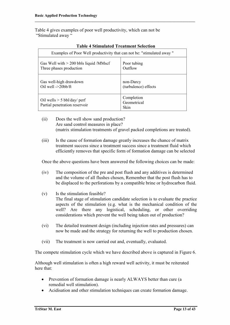
(vii) The treatment is now carried out and, eventually, evaluated. The compete stimulation cycle which we have described above is captured in Figure 6. Although well stimulation is often a high reward well activity, it must be reiterated here that:
Prevention of formation damage is nearly ALWAYS better than cure (a remedial well stimulation).
Acidisation and other stimulation techniques can create formation damage.
Basic Applied Production Technology ___________________________________________________________________________________
TriStar M. East Page 14 of 43
These are turn for clastic formation and many carbonate reservoirs as well
5- Selection of (Chemical) Treatment Type The chosen chemical treatment fluid should be targeted at the particular type and location of the formation damage to be removed or treated. the formation damage / impairment may be related to:
Figure 5 The Stimulation Cycle
Figure 6 Type & location of formation damage for cased &
openhole completions

Basic Applied Production Technology ___________________________________________________________________________________
TriStar M. East Page 15 of 43
(i) drilling completion or workover operations , (ii) produced or (continually ) injected fluids , (iii) injected fluids during specific well operation e.g. we killing .
Table 5 can be used to select the optimum type of chemical treatment once the type and location of the formation damage / impairment has been identified.
Table 5 Chemical treatment types
Treatment Objective Location Comments Acid (inorganic ) and solvent (organic ) washes
Remove flow restrictions e.g. Inorganic/ wax scale Kill pills, etc
Tubing , perforation and completion
Circulated in well – not injected into formation
Matrix acidising
Dissolve rock components (dirll solids precipates clay etc) and formation damage to improve well / formation connectivity
Near wellbore {<1m depth form sand face )
Other matrix treatments
Solvents and surfactants remove Emulsions, wax etc. from oily wells and inhibitor residues from gas wells Chemical inhibitor squeezes Prevent scaling etc. during Well production
Near wellbore {<1m} at depth (<10m) From wellbore
Large volume treatment Inhibitor returns with Produced fluid
6- Potential Formation Damage Caused By Matrix Stimulation Fluids The reaction of formation rock / insitu (formation / injected) fluids with incorrectly chosen stimulation fluid may generate further formation damage / impairment. Such sources of formation damage include: (i) Deconsolidation of the rock matrix due to the acid dissolving the cementing
material that holds the sand grains together. (Temporary) sand production is often observed when a well is returned to production after and acid stimulation.
(ii) Generation of migrating, small diameter particles (“fines”) which can block
the pore throats. These particles result from the acid only partly dissolving the formation minerals present between the grains. This allows insoluble, small diameter, particles to be created and injected into the formation pore throats where bridging and blockage can occur.
(iii) The products created by the chemical reaction between the acid and the
formation rock can be insoluble in the spent stimulation fluid. This is called secondary precipitation. This precipitation process leads to blockage of the prose and pore throats (impairment). This precipitation often does occur immediately – this implies that there is an opportunity to either:
Basic Applied Production Technology ___________________________________________________________________________________
TriStar M. East Page 16 of 43
a) Produce the (spent ) acid (i.e return the well to production) or
b) Inject the acid deep into the formation where any precipitation will have limited effect on the well productivity.
(iv) Fluid incompatibilities. A matrix acidising treatment consists of
sequentially injecting a series of fluids . It must be checked that these fluids are compatible with each other and with the formation fluids i.e. to not form a (solid) precipitate at the prevailing, downhole temperature when mixed in any proportion. Further, for the acid fluids which react with the formation; both the “fresh “(unreacted) and the “spent “(reacted) acids need to be tested in this way.
(v) Acid precipitation of an insoluble sludge when mixed with the crude oil
.This is particularly true for asphaltenic crudes and for acid s containing ferric cations (rust – or ferric oxide – is a corrosion product produced by steel surfaces e.g. the tubing internals which is dissolved in the acid as it is injected into the well ). Such sludge precipitation can be avoided by avoided by injecting a compatible hydrocarbon based preflush to displace the crud oil away from the wellbore and the following acid.
(vi) Surfactants .Surfactants added to the treatment fluid may create a (highly )
viscous emulsion with the crude oil leading to blockage of the pores by this low mobility fluids . Prescreening laboratory tests in which a sample of the treatment fluid and the crude oil are shaken together and then the mixture examined for emulsion formation. A series of such trials can be used to select a suitable, non- emulsifying. Surfactant.
(vii) Wettability changes .Surfactants can change the wettability of the pore
surfaces An oil wet formation has a lower permeability to oil than the equivalent water formation. Once again, any surfactants that are planned to be used should be tested as described above.
(viii) "Water blocks" significant volumes of water are injected into the formation
during the stimulation treatment. This may lead to increased water saturation (water block) in the near wellbore area and can take a long time to disappear (months or even year) from low permeability formation. This can be minimized by the addition of gas to the stimulation fluid or the (partial ) replacement of water by more volatile solvents
All these forms of formation damage were previously. Nonacid, matrix stimulation treatments also show these effects – apart from (i) and (iii). Surfactants are capable of mobilizing loosely bound, small particles (such as clay articles or other “fines “ ) which can then reduce the permeability by blocking the pore aroats, a source of formation damage similar to (ii). It is clear from above that formulation of the acid and the other fluid flushes employed the key to ensuring that to formation damage due to the stimulation treatment does not occur or, if it is unavoidable, is at least minimized.
Basic Applied Production Technology ___________________________________________________________________________________
TriStar M. East Page 17 of 43
7- Matrix Stimulation Fluid Section The mineralogy and chemistry of the formation, together with the chemistry of the formation fluid and that the formation damage, combine to give the stimulation fluid selection criteria. The can be summarized as a balance between the:
(i) Positive effects e.g. solubility of the formation and formation damage in the selected fluid, and the
(ii) Negative effects e.g. deconsolidation “fines “generation, secondary precipitates etc.
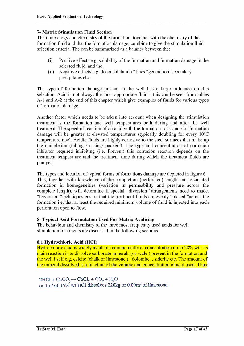
The type of formation damage present in the well has a large influence on this selection. Acid is not always the most appropriate fluid – this can be seen from tables A-1 and A-2 at the end of this chapter which give examples of fluids for various types of formation damage. Another factor which needs to be taken into account when designing the stimulation treatment is the formation and well temperatures both during and after the well treatment. The speed of reaction of an acid with the formation rock and / or formation damage will be greater at elevated temperatures (typically doubling for every 10oC temperature rise). Acidic fluids are highly corrosive to the steel surfaces that make up the completion (tubing / casing/ packers). The type and concentration of corrosion inhibitor required inhibiting (i.e. Prevent) this corrosion reaction depends on the treatment temperature and the treatment time during which the treatment fluids are pumped The types and location of typical forms of formations damage are depicted in figure 6. This, together with knowledge of the completion (perforated) length and associated formation in homogeneities (variation in permeability and pressure across the complete length), will determine if special “diversion “arrangements need to made. “Diversion “techniques ensure that the treatment fluids are evenly “placed “across the formation i.e. that at least the required minimum volume of fluid is injected into each perforation open to flow. 8- Typical Acid Formulation Used For Matrix Acidising The behaviour and chemistry of the three most frequently used acids for well stimulation treatments are discussed in the following sections 8.1 Hydrochloric Acid (HCI) Hydrochloric acid is widely available commercially at concentration up to 28% wt. Its main reaction is to dissolve carbonate minerals (or scale ) present in the formation and the well itself e.g. calcite (chalk or limestone ) , dolomite , siderite etc. The amount of the mineral dissolved is a function of the volume and concentration of acid used. Thus:
Basic Applied Production Technology ___________________________________________________________________________________
TriStar M. East Page 18 of 43
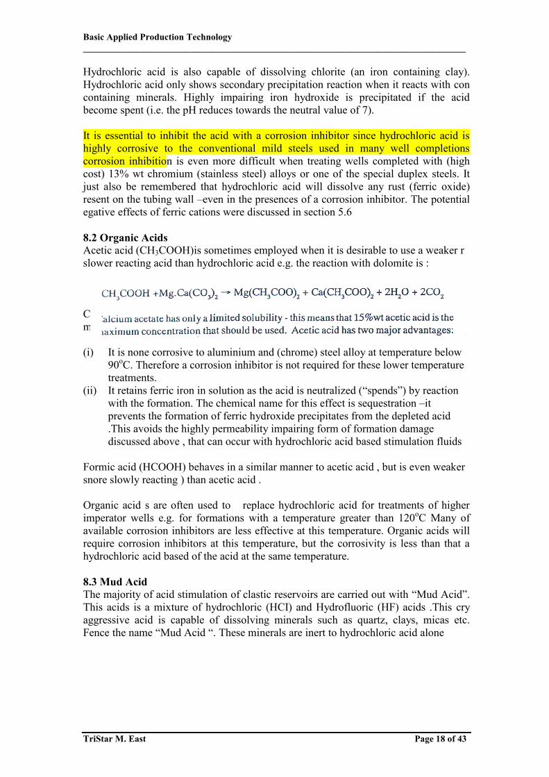
Hydrochloric acid is also capable of dissolving chlorite (an iron containing clay). Hydrochloric acid only shows secondary precipitation reaction when it reacts with con containing minerals. Highly impairing iron hydroxide is precipitated if the acid become spent (i.e. the pH reduces towards the neutral value of 7). It is essential to inhibit the acid with a corrosion inhibitor since hydrochloric acid is highly corrosive to the conventional mild steels used in many well completions corrosion inhibition is even more difficult when treating wells completed with (high cost) 13% wt chromium (stainless steel) alloys or one of the special duplex steels. It just also be remembered that hydrochloric acid will dissolve any rust (ferric oxide) resent on the tubing wall –even in the presences of a corrosion inhibitor. The potential egative effects of ferric cations were discussed in section 5.6 8.2 Organic Acids Acetic acid (CH3COOH)is sometimes employed when it is desirable to use a weaker r slower reacting acid than hydrochloric acid e.g. the reaction with dolomite is : Calcium acetate has only a limited solubility- this means that 15% wt acetic acid is the maximum concentration that should be used. Acetic acid has two major advantages: (i) It is none corrosive to aluminium and (chrome) steel alloy at temperature below
90oC. Therefore a corrosion inhibitor is not required for these lower temperature treatments.
(ii) It retains ferric iron in solution as the acid is neutralized (“spends”) by reaction with the formation. The chemical name for this effect is sequestration –it prevents the formation of ferric hydroxide precipitates from the depleted acid .This avoids the highly permeability impairing form of formation damage discussed above , that can occur with hydrochloric acid based stimulation fluids
Formic acid (HCOOH) behaves in a similar manner to acetic acid , but is even weaker snore slowly reacting ) than acetic acid . Organic acid s are often used to replace hydrochloric acid for treatments of higher imperator wells e.g. for formations with a temperature greater than 120oC Many of available corrosion inhibitors are less effective at this temperature. Organic acids will require corrosion inhibitors at this temperature, but the corrosivity is less than that a hydrochloric acid based of the acid at the same temperature. 8.3 Mud Acid The majority of acid stimulation of clastic reservoirs are carried out with “Mud Acid”. This acids is a mixture of hydrochloric (HCI) and Hydrofluoric (HF) acids .This cry aggressive acid is capable of dissolving minerals such as quartz, clays, micas etc. Fence the name “Mud Acid “. These minerals are inert to hydrochloric acid alone
Basic Applied Production Technology ___________________________________________________________________________________
TriStar M. East Page 19 of 43
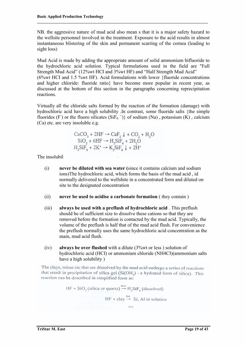
NB. the aggressive nature of mud acid also mean s that it is a major safety hazard to the wellsite personnel involved in the treatment. Exposure to the acid results in almost instantaneous blistering of the skin and permanent scarring of the cornea (leading to sight loss) Mud Acid is made by adding the appropriate amount of solid ammonium bifluoride to the hydrochloric acid solution. Typical formulations used in the field are "Full Strength Mud Acid” (12%wt HCI and 3%wt HF) and “Half Strength Mud Acid” (6%wt HCI and 1.5 %wt HF). Acid formulations with lower {fluoride concentrations and higher chloride: fluoride ratio} have become more popular in recent year, as discussed at the bottom of this section in the paragraphs concerning reprecipitation reactions. Virtually all the chloride salts formed by the reaction of the formation (damage) with hydrochloric acid have a high solubility .In contrast, some fluoride salts {the simple fluorides (F-) or the fluoro silicates (SiF6 --)} of sodium (Na) , potassium (K) , calcium (Ca) etc. are very insoluble e.g. The insolubility of these salts implies that mud acid should:
(i) never be diluted with sea water (since it contains calcium and sodium
ions)The hydrochloric acid, which forms the basis of the mud acid , id normally delivered to the wellshite in a concentrated form and diluted on site to the designated concentration
(ii) never be used to acidise a carbonate formation ( they contain )
(iii) always be used with a preflush of hydrochloric acid . This preflush
should be of sufficient size to dissolve these cations so that they are removed before the formation is contacted by the mud acid. Typically, the volume of the preflush is half that of the mud acid flush. For convenience the preflush normally uses the same hydrochloric acid concentration as the main, mud acid flush.
(iv) always be over flushed with a dilute (3%wt or less ) solution of
hydrochloric acid (HCI) or ammonium chloride (NH4CI)(ammonium salts have a high solubility )
Basic Applied Production Technology ___________________________________________________________________________________
TriStar M. East Page 20 of 43
NB: SiO2 represents quartz or other forms of silica; while Al and Si represents uminium and silicon respectively. They are the constituents of clays and micas. These (re) precipitation reactions can not be avoided but their effect can be minimized:
(i) For some formations, an increase in the HCI: HF ratio of the mud acid formulation will reduce the amount of (re) precipitation
(ii) Since the (re) precipitation reaction occurs slowly, its damage effects can
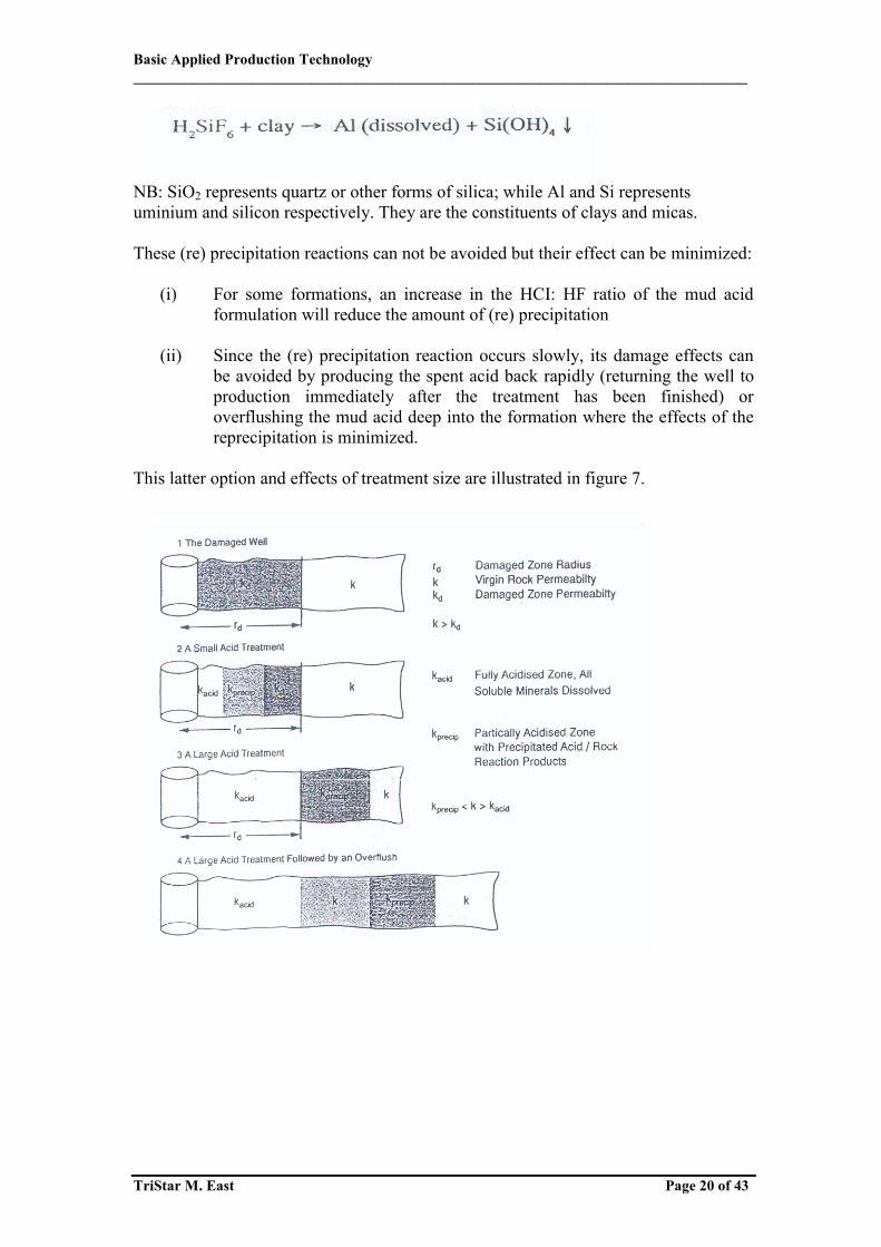
be avoided by producing the spent acid back rapidly (returning the well to production immediately after the treatment has been finished) or overflushing the mud acid deep into the formation where the effects of the reprecipitation is minimized.
This latter option and effects of treatment size are illustrated in figure 7.

Basic Applied Production Technology ___________________________________________________________________________________
TriStar M. East Page 21 of 43
8.4 Selection of Acid Composition
Figure 8 A mud acid treatment
The chemistry of a mud acid treatment is pictured in figure 8. It illustrates how the impairment formation clays and inter – granular cements are removed by the mud acid and partially replaced by secondary reaction products. However, there is an overall increase in porosity and permeability, leading to stimulation of the well.
Table 6 Acid selections Formation Characteristics Acid Recommendation Comment
HCI solubility >15% HCI only HF causes CaF2precipitation Organic acids ED TA/ surfactant Treatment an option 10%HCI solubility >15% Increase HCI preflush
volume Ensure all carbonate minerals dissolved Prior too mud acid
HIGH PERMEABLITY (>100MD) High quartz (80%) low clay (5%) 12%HCI –3% HF Regular mud acid High fields par/illite (>15%) 13.5% HCI –1.5% HF Avoid fluosilicate precipitation High clay (>10%) 6.5% HCI –1% HF Reduced potential migratory fines due to
partial dissolution High (Fe ) chlorite clay 3|% HCI –0.5% HF Avoid iron dissolution. HCI preflush with
Fe sequestrant an option LOW PERMEABILTY (<100 MD ) High quartz (80%); low clay (5%) 6% HCI –1.5% HF Reduce migrating fines potential High felds par /illite 6% HCI –0.5% HF Avoid fluosilicate precipitation High clay (>10%) 6% HCI –0.5% HF Reduce migrating fines potential High (Fe) chlorite clay 3% HCI –0.5% HF Avoid iron dissolution HCI preflush with Fe sequestrant an option
Replace at least half of the HCI by HCOOH in the region 120oC – 170oC bottom hole temperature Replace all the HCI by HCOOH for temperatures greater than 170oC NB 1% wt HCI =1.3% wt HCOOH
Basic Applied Production Technology ___________________________________________________________________________________
TriStar M. East Page 22 of 43
The ideas presented in the previous section, combined with laboratory core flooding and field experience, have shown the need to adjust the mud acid formulation to the type of formation mineralogy and damage that is being treated. This experience is consolidated in table 6. Salient points of note are:
(i) Formations with a high (>10%wt), solubility in hydrochloric acid require a larger (hydrochloric acid) preflush. Mud acid should not be used once this solubility level increases to 15% wt or higher.
(ii) Higher permeability formations with low clay content can be stimulated
with fluids containing a higher HF concentration. Increasing clay contents and the presence of certain minerals require lower HF acid concentrations and higher HCI: HF ratios.
(iii) A similar approach is followed for lower permeability formations except
that lower acid concentrations are employed even for the “cleanest” (low clay content) formations.
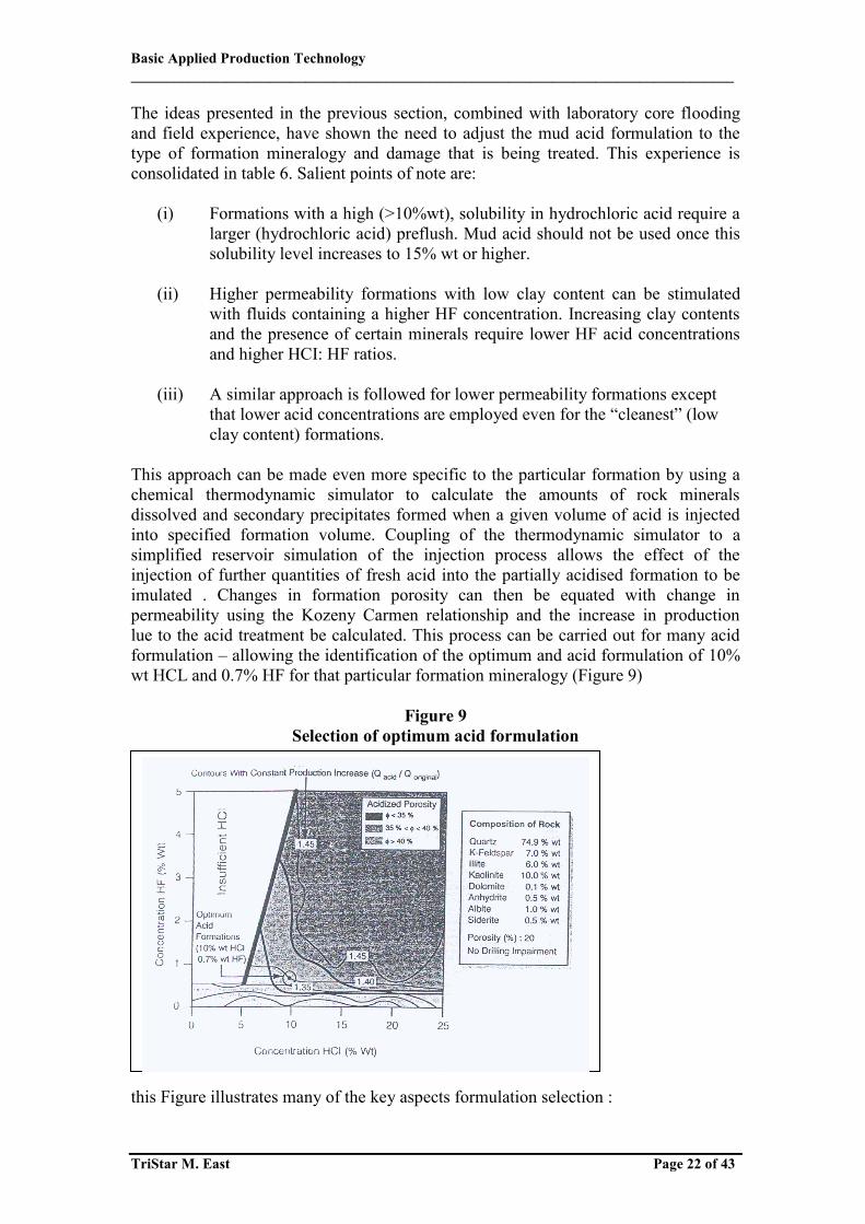
This approach can be made even more specific to the particular formation by using a chemical thermodynamic simulator to calculate the amounts of rock minerals dissolved and secondary precipitates formed when a given volume of acid is injected into specified formation volume. Coupling of the thermodynamic simulator to a simplified reservoir simulation of the injection process allows the effect of the injection of further quantities of fresh acid into the partially acidised formation to be imulated . Changes in formation porosity can then be equated with change in permeability using the Kozeny Carmen relationship and the increase in production lue to the acid treatment be calculated. This process can be carried out for many acid formulation – allowing the identification of the optimum and acid formulation of 10% wt HCL and 0.7% HF for that particular formation mineralogy (Figure 9)
Figure 9 Selection of optimum acid formulation
this Figure illustrates many of the key aspects formulation selection :
Basic Applied Production Technology ___________________________________________________________________________________
TriStar M. East Page 23 of 43
(i) Obtain the highest possible Production Increase (K acid / K original) consistent with:
(ii) Minimization the increase in porosity (i.e. chance of sand production by
deconsolidation of the formation). It can be seen from figure 9that that this calculation did not include any formation damage. an alternative formulation, 9%wt HCL and 1%wt HF, also meets the above criteria. This second formulation has a higher HF acid content, which would be capable of removing greater amounts of, for example, clays from drilling fluids than the 0.7 % wt HF formulation. Both these formulations have a high HCL: HF ratio, which is suitable for treating formations with significant clay content. 8.5 Selection of Treatment Volume The next stage in treatment design is the selection of the treatment volume. This can be based on:
Table 7 Typical Mud Acid treatment volumes
Formation Temperature <150oF 150-250oF >250oF Permeability Volume of mud acid (US gal /ft perforations) <20mD 100 50 50 20-100mD 150 100 100 >100mD 200 150 100
(i) Field experience when treating wells in the same or similar field. Often
between 50% and 100% of the volumes suggested in Table 7 are used
(ii) Practical considerations such as logistics e.g
(a) How much acid can be delivered to the delivered to the wellsite? Or (b) How large an acid the volume pumpable during daylight hours?
(iii) Economics (how much acid can we afford based on excepted gain in hydrocarbon production?)
(iv) Laboratory core flow testing (acid volume required to increase the
permeability by a target amount). The core may be pre-treated to include damage to the core inlet face by the suspected form of formation damage.
Laboratory testing in support of matrix stimulation campaigns can also include:
a) Identification of the formation mineralogy by use of thin sections, X-ray diffraction or Scanning Electron Microscope studies
b) petrographic analysis of formation samples yields information on the type and
location of the minerals , porosity , cementation and clays
Basic Applied Production Technology ___________________________________________________________________________________
TriStar M. East Page 24 of 43
c) Fluid – Fluid compatibility tests can be carried tests can be carried out using API RP (Recommended Practice) 42 test methodology. Carrying out these testes will help ensure that all the fluids used are compatible with each other and the insitu crude oil. Typical tests that can be carried out include checks to see if:
- a sludge is formed by the crud oil * on contacting with acid ,
- a “fines “ stabilized acid /oil* emulsion can be formed, * these two tests require a fresh (non – aged) crude oil sample.
- a viscous oil based mud / acid emulsion is formed
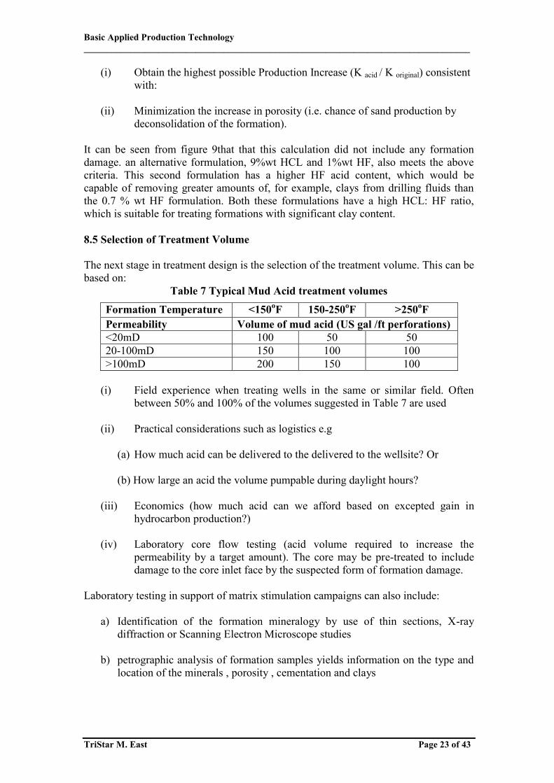
(v) Theoretical calculation based on the formation mineralogy and formation
damage as used in Figure 9 and described at the end of section 5.8.3. This technique has been applied to a well in which formation damage was present to a depth of 30cm. The results summarized in Figure 10. This Figure indicates that an acid volume of 16 US gals /ft perforations is required to achieve the optimum Productivity Index (PI) for both unimpaired (no formation damage) and impaired (formation damage present) wells. However, this calculation assumes prefect placement of the acid (see section 5.8.8) in practice, a larger acid volume has to be injected to ensure that each perforation receives the required treatment volume of 16 US gal /ft of perforations
Figure 10
Selection of optimum acid volume
(i) preflush: 4% of mud acid volume rising to 100% as carbonate content increases .
(ii) Main flush: mud acid volume between 50% and 100%of Table 7 values.
(iii) Post flush: 10% of mud acid volume if production resumed immediately
increasing to 100% -200% if production can not be resumed within 4 hours.
Basic Applied Production Technology ___________________________________________________________________________________
TriStar M. East Page 25 of 43
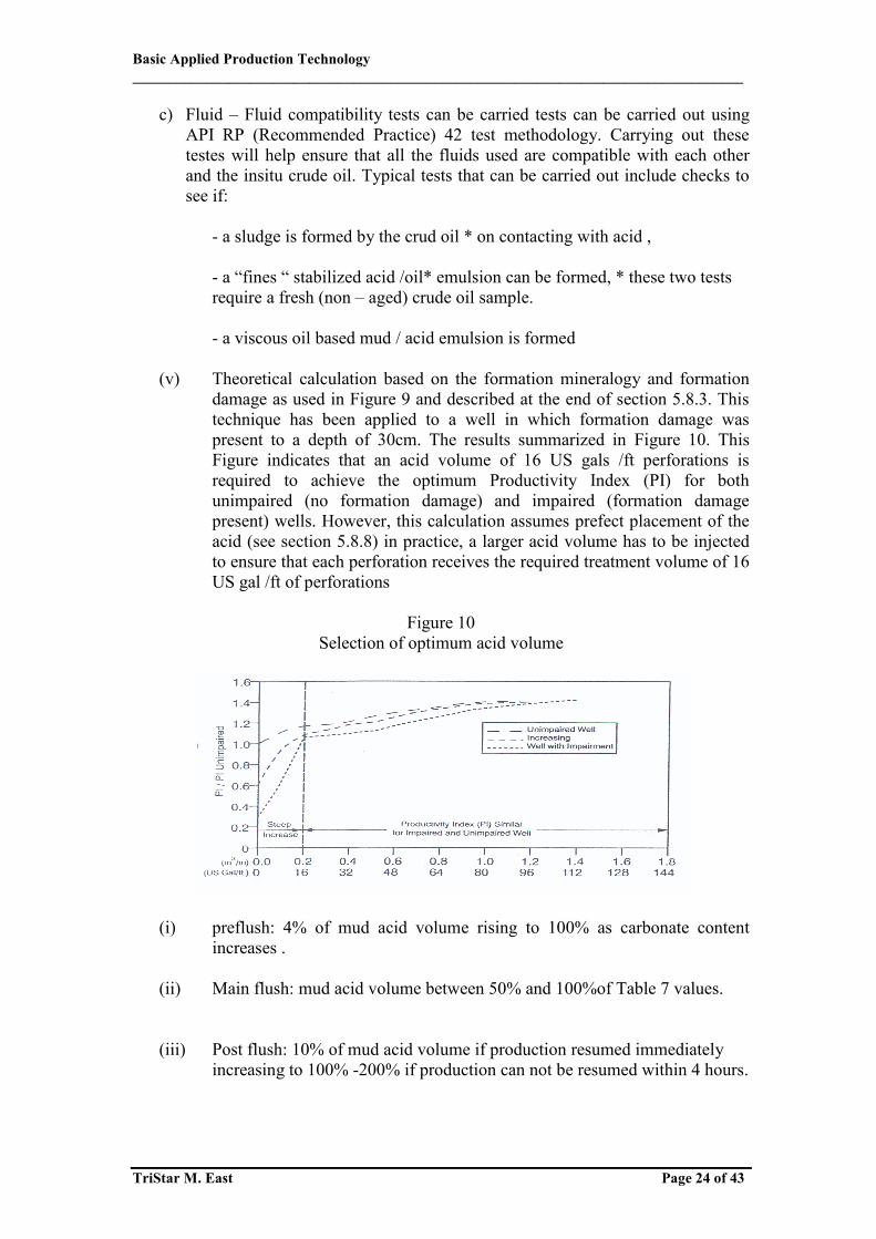
5.8.6 Selection of Injection Matrix treatment fluids have to be injected below the Fracture Propagation Pressure (FPP) (this term is explained in Chapter 6 on Hydraulic Fracturing) to ensure that the fluids are injected radially from the wellbore through the matrix. The maximum allowable injection rate can be calculated form the equation: This safety margin should be larger if the fracture gradient is not well known. This version of the radial inflow equation assumes the injected and reservoir fluids do not differ greatly in viscosity and ignores transient flow effects. This equation allows the maximum injection rate to be calculated for a constant bottom hole pressure as a function of skin and injection rate. The Bottom Hole Flowing Pressure can be translated to Wellhead Pressure by applying the techniques discussed in Chapter1. This requires knowledge of the treatment flow rate & fluid density, depth of the top perforation and internal diameter roughness of the tubing etc. It can be used to prepare a graph similar to Figure 11 in which the Wellhead Pressure is plotted against the treatment injection rate for a number of different values of the well skin. N.B only injection rates bellows the FPP need to be considered.
Basic Applied Production Technology ___________________________________________________________________________________
TriStar M. East Page 26 of 43
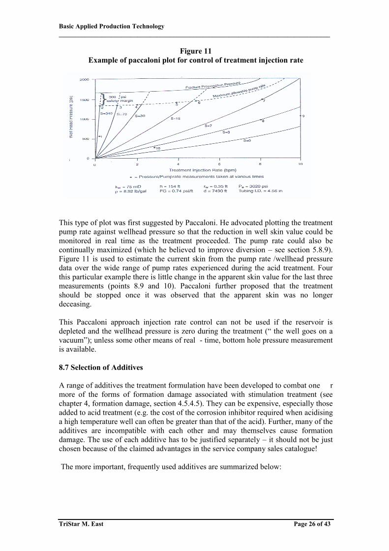
Figure 11 Example of paccaloni plot for control of treatment injection rate
This type of plot was first suggested by Paccaloni. He advocated plotting the treatment pump rate against wellhead pressure so that the reduction in well skin value could be monitored in real time as the treatment proceeded. The pump rate could also be continually maximized (which he believed to improve diversion – see section 5.8.9). Figure 11 is used to estimate the current skin from the pump rate /wellhead pressure data over the wide range of pump rates experienced during the acid treatment. Four this particular example there is little change in the apparent skin value for the last three measurements (points 8.9 and 10). Paccaloni further proposed that the treatment should be stopped once it was observed that the apparent skin was no longer deceasing. This Paccaloni approach injection rate control can not be used if the reservoir is depleted and the wellhead pressure is zero during the treatment (“ the well goes on a vacuum”); unless some other means of real - time, bottom hole pressure measurement is available. 8.7 Selection of Additives A range of additives the treatment formulation have been developed to combat one r more of the forms of formation damage associated with stimulation treatment (see chapter 4, formation damage, section 4.5.4.5). They can be expensive, especially those added to acid treatment (e.g. the cost of the corrosion inhibitor required when acidising a high temperature well can often be greater than that of the acid). Further, many of the additives are incompatible with each other and may themselves cause formation damage. The use of each additive has to be justified separately – it should not be just chosen because of the claimed advantages in the service company sales catalogue! The more important, frequently used additives are summarized below:
Basic Applied Production Technology ___________________________________________________________________________________
TriStar M. East Page 27 of 43
(i) Corrosion Inhibitors This additive type is almost always required for acid treatment due to the corroding reaction of acid on steel: Fe + 2H+ Fe++ (dissolved) + H2 (gas) The (acid) corrosion rate increases rapidly with increase in temperature. Further, the corrosion inhibitor losses its effectiveness as the temperature and treatment time increases (due to degradation). A field proven “rule- of – thumb” is that a maximum weight loss of 0.05 lb /ft2 of tubing area (eqivalent to the removal of 0.001 in of the tubing wall thickness) during the treatment duration is acceptable. This implies that the allowable corrosion rate decreases as the acid treatment time increase. Further, the corrosion should be in the form of a general weigh loss type rather than pitting or stress corrosion. The above allows a specification to be developed for the corrosion inhibition of the acid. The type and concentration of corrosion inhibitor chosen will depend on the bottom hole temperature, the type of steel contacted and the expected treatment duration. N.B. The “spent” acid produced back after the treatment when the well is returned to production is often highly acidic and will corrode the tubing at similar rate to the fresh acid. This is because the corrosion inhibitor has been depleted by reaction with the acid and absorption on the formation. Injection of extra corrosion inhibitor may be considered during this phase if, for example the well is being returned to production by nitrogen lifting with a coiled tubing unit. (ii) Sequestering Agents Both the ferrous (Fe++) and ferric (Fe+++) forms of iron will precipitate as the acid “spends” (pH increases). They both form an amorphous, high volume iron hydroxide precipitate, which is highly efficient at creating formation damage. Fe+++ is by far most insoluble form (see Table 8) Ferric hydroxide already has a low solubility at pH value greater than 2, though this value is increased to 6 when mud acid is being used since sequestration takes place due the presence of the fluoride ion (F). By contrast, ferrous hydroxide precipitation is delayed until the p H rises to value greater than 6. The main source of Fe+++ is the acid reacting with rust in the surface tanks, flowlines and millscale on the tubing. The Fe++ is mainly (>80%) derived from the formation minerals e.g. chlorite siderite, pyrite etc. A number of "sequestering"– or solubilising – agents are available to increase the solubility of iron by forming soluble complexes. The concentration of "sequestrant" required to prevent iron hydroxide precipitation depends on the expected ferric iron (Fe+++) concentration. This is because it is unsual for the p H of the “spent “ acid to increase to value of 6 when treating clastic formations unless they contain a high percentage of carbonates i.e. ferrous hydroxide does not normally precipitate under these circumstances. The cheapest sequestering agent is citric acid. This has the disadvantage that the maximum concentration allowable –and the maximum amount of iron cations that can be sequestered- is limited by the solubility of calcium citrate. A more expensive

Basic Applied Production Technology ___________________________________________________________________________________
TriStar M. East Page 28 of 43
alternative, which can be used at higher concentrations, is EDTA (Ethlene Diamine Tetracetic Acid). An alternative approach preventing ferric hydroxide precipitation is to reduce the Fe+++ to Fe++ by Erythorbic acid or ascorbic acid (vitamin C). N.B. As discussed above in Section 5.8.5, Fe+++ can catalyse the formation of an asphaltenic sludge when the acid contacts some crude oils. (iii) Solvents / Mutual Solvents / Surfactants Use of these materials may reduce emulsion formation but can also be the cause of very able emulsion formation. Further, they may render the corrosion inhibitor ineffec – ve by preventing the absorbtion of the inhibitor onto the steel surface. They can be seful in some circumstances – but their employment needs to be properly justified and full range of compatibility tests carried out (API RP 42 referred to earlier) (iv) Nitrogen Nitrogen gas may be added to the treatment fluid to assist flow back of the spent acid and hence a rapid clean up when treating gas wells or depleted zones. 8.8 Selection of Treatment Type The manner of execution of most matrix treatments falls into one of two classes: (i) “Bullheading “-this term describes a treatment, which is pumped down the production tubing. The treatment – particularly if it employs acids – can displace rust, scale, pipe dope, etc. Present on the tubing’ sinner wall into the formation; leading to formation damage. Sometimes the matrix treatment is carried out prior to running the tubing. This can be even worse since dried mud, cement, etc. Which are present on the casing wall can now also be dislodged as well as the damaging materials referred to above. The formation pressure is sufficiently high, or artificial lift is installed, it is possible clean the tubing with a pre treatment (known as "pickling "). This involves injecting to the tubing a volume of acid – usually equal to 20% of the tubing contents –and displacing it until the leading front of the acid is safe distance above the top perforation. The acid, along with the dislodged, potentially impairing, is then produced back to the surface. Bullheading of ( cold ) fluids from the surface also causes the tubing to contract in length .If this contraction generates too large tensile stresses in the tubing , it may part cause unseating of the packer both these problems may be avoided by : (ii) Pumping the treatment through a coiled tubing (CT) the end of which is positioned opposite the perforations. Prior to the treatment being carried out the inside of the CT often need s to be cleaned e.g. by “pickling “with acid however, this can relatively easily be carried out at surface, if necessary.

Basic Applied Production Technology ___________________________________________________________________________________
TriStar M. East Page 29 of 43
Oiled tubing has smaller diameter than production tubing – so the maximum pump is limited (due to friction) and the use of ball sealers for diversion. 8.9 Selection of Diversion Technique Most formation are not homogeneous –in practice the perforated interval will contain a number of formation layers with a range of permeabilities , most likely , differing levels of skin damage . The treatment fluid injection rate into each layer will be governed by the radial flow equation since the pressure in the wellbore is in all probability very similar for all the layers. This situation is depicted in figure 12, which shows that by far the highest proportion of the acid is injected into the middle, high permeability layer (Zone B). The natural tendency for the acid to be injected into this layer was accentuated because this layer also has the lowest skin value. This was due to depth of penetration of the formation damage being the least. The Figure shows that the formation damage in zone B alone was removed by the treatment employing V1, a small treatment volume. Even doubling the treatment volume to V2 does not allow the acid successfully remove the formation damage in Zone A. N.B. The injection rate into a particular layer, relative to the other layers, increases rapidly once the formation damage has been removed by the treatment. Obtaining an even distribution of the (acid) treatment is further complicated if the layers have
Basic Applied Production Technology ___________________________________________________________________________________
TriStar M. East Page 30 of 43
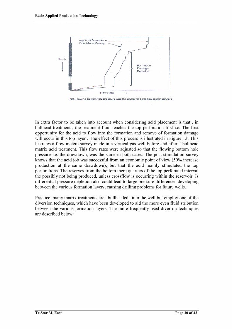
In extra factor to be taken into account when considering acid placement is that , in bullhead treatment , the treatment fluid reaches the top perforation first i.e. The first opportunity for the acid to flow into the formation and remove of formation damage will occur in this top layer . The effect of this process is illustrated in Figure 13. This lustrates a flow metere survey made in a vertical gas well before and after “ bullhead matrix acid treatment. This flow rates were adjusted so that the flowing bottom hole pressure i.e. the drawdown, was the same in both cases. The post stimulation survey knows that the acid job was successful from an economic point of view (50% increase production at the same drawdown); but that the acid mainly stimulated the top perforations. The reserves from the bottom there quarters of the top perforated interval the possibly not being produced, unless crossflow is occurring within the reservoir. Is differential pressure depletion also could lead to large pressure differences developing between the various formation layers, causing drilling problems for future wells. Practice, many matrix treatments are “bullheaded “into the well but employ one of the diversion techniques, which have been developed to aid the more even fluid stribution between the various formation layers. The more frequently used diver on techniques are described below:
Basic Applied Production Technology ___________________________________________________________________________________
TriStar M. East Page 31 of 43
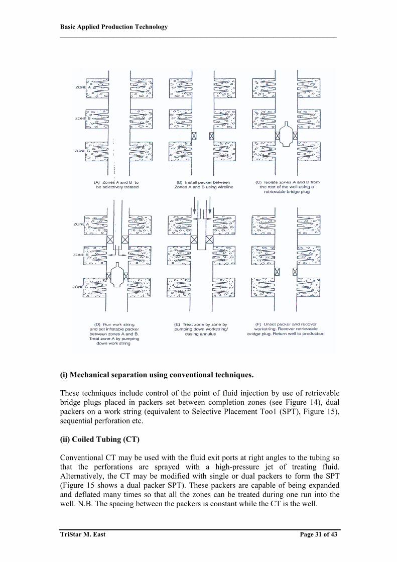
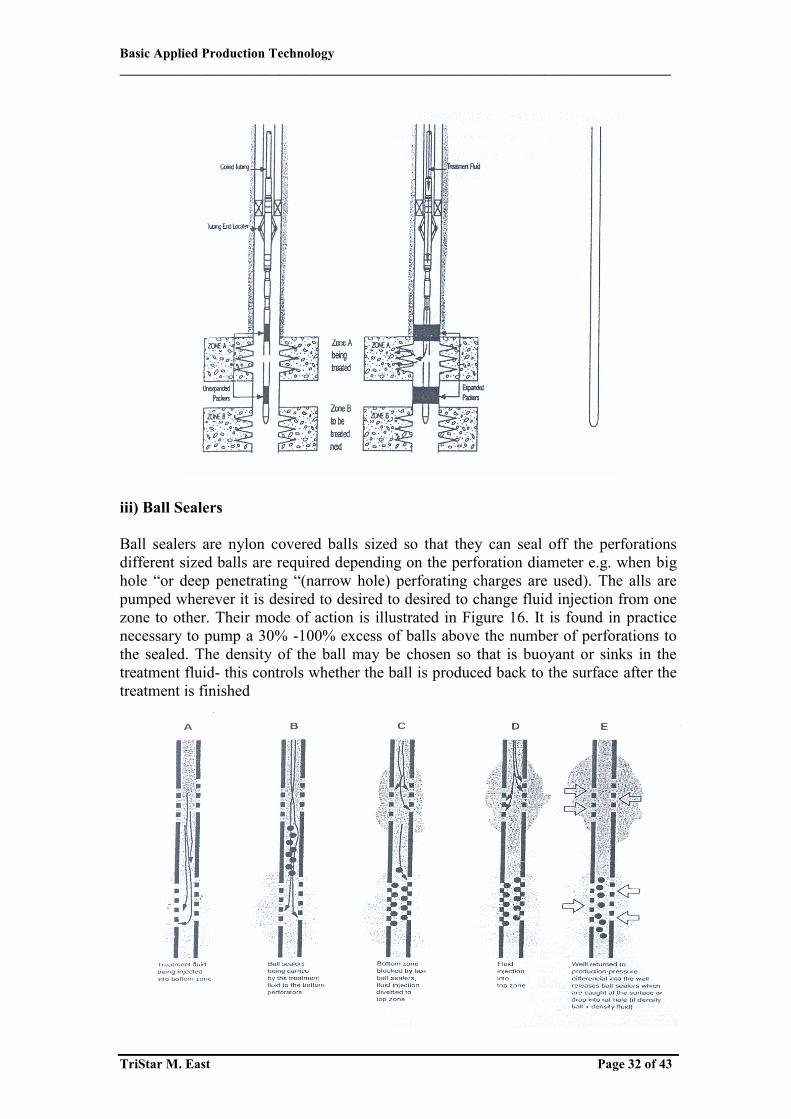
(i) Mechanical separation using conventional techniques. These techniques include control of the point of fluid injection by use of retrievable bridge plugs placed in packers set between completion zones (see Figure 14), dual packers on a work string (equivalent to Selective Placement Too1 (SPT), Figure 15), sequential perforation etc. (ii) Coiled Tubing (CT) Conventional CT may be used with the fluid exit ports at right angles to the tubing so that the perforations are sprayed with a high-pressure jet of treating fluid. Alternatively, the CT may be modified with single or dual packers to form the SPT (Figure 15 shows a dual packer SPT). These packers are capable of being expanded and deflated many times so that all the zones can be treated during one run into the well. N.B. The spacing between the packers is constant while the CT is the well.
Basic Applied Production Technology ___________________________________________________________________________________
TriStar M. East Page 32 of 43
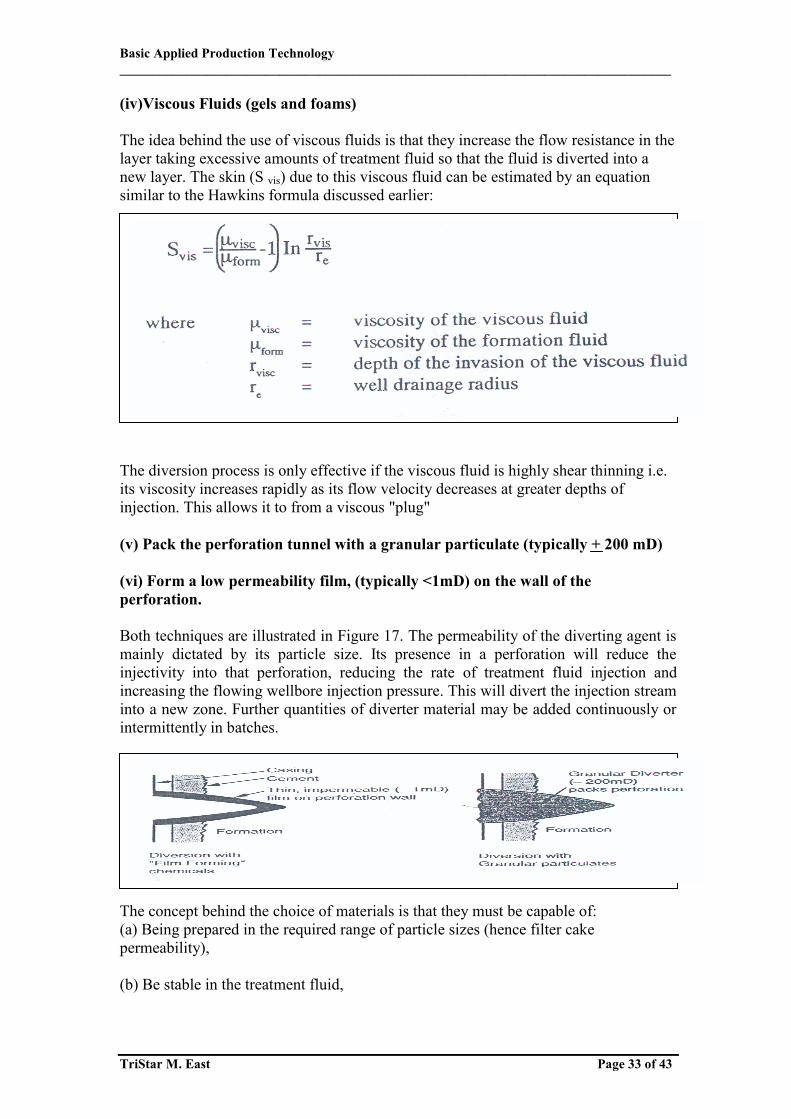
iii) Ball Sealers Ball sealers are nylon covered balls sized so that they can seal off the perforations different sized balls are required depending on the perforation diameter e.g. when big hole “or deep penetrating “(narrow hole) perforating charges are used). The alls are pumped wherever it is desired to desired to desired to change fluid injection from one zone to other. Their mode of action is illustrated in Figure 16. It is found in practice necessary to pump a 30% -100% excess of balls above the number of perforations to the sealed. The density of the ball may be chosen so that is buoyant or sinks in the treatment fluid- this controls whether the ball is produced back to the surface after the treatment is finished
Basic Applied Production Technology ___________________________________________________________________________________
TriStar M. East Page 33 of 43
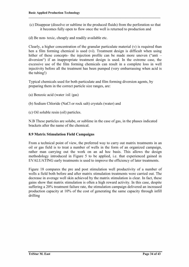
(iv)Viscous Fluids (gels and foams) The idea behind the use of viscous fluids is that they increase the flow resistance in the layer taking excessive amounts of treatment fluid so that the fluid is diverted into a new layer. The skin (S vis) due to this viscous fluid can be estimated by an equation similar to the Hawkins formula discussed earlier: The diversion process is only effective if the viscous fluid is highly shear thinning i.e. its viscosity increases rapidly as its flow velocity decreases at greater depths of injection. This allows it to from a viscous "plug" (v) Pack the perforation tunnel with a granular particulate (typically + 200 mD) (vi) Form a low permeability film, (typically <1mD) on the wall of the perforation. Both techniques are illustrated in Figure 17. The permeability of the diverting agent is mainly dictated by its particle size. Its presence in a perforation will reduce the injectivity into that perforation, reducing the rate of treatment fluid injection and increasing the flowing wellbore injection pressure. This will divert the injection stream into a new zone. Further quantities of diverter material may be added continuously or intermittently in batches. The concept behind the choice of materials is that they must be capable of: (a) Being prepared in the required range of particle sizes (hence filter cake permeability), (b) Be stable in the treatment fluid,
Basic Applied Production Technology ___________________________________________________________________________________
TriStar M. East Page 34 of 43
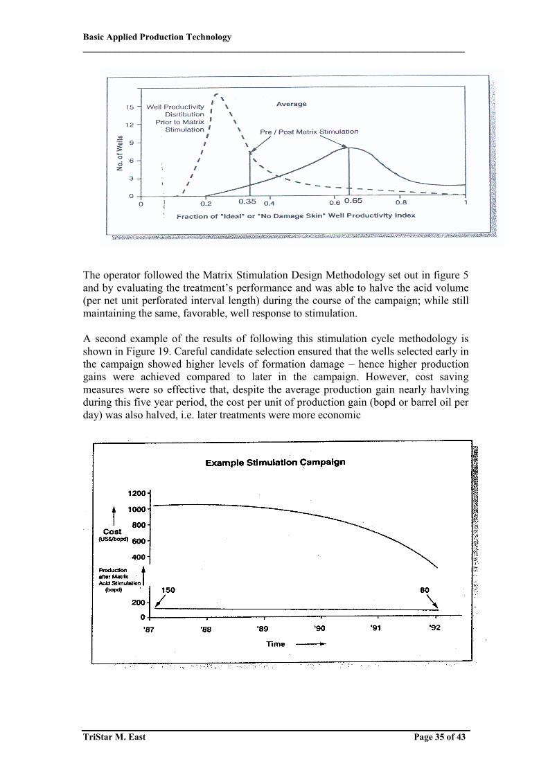
(c) Disappear (dissolve or sublime in the produced fluids) from the perforation so that it becomes fully open to flow once the well is returned to production and (d) Be non- toxic, cheaply and readily available etc. Clearly, a higher concentration of the granular particulate material (v) is required than hen a film forming chemical is used (vi). Treatment design is difficult when using hither of these concepts- the injection profile can be made more uneven (“anti – diversion“) if an inappropriate treatment design is used. In the extreme case, the excessive use of the film forming chemicals can result in a complete loss in well injectivity before all the treatment has been pumped (very embarrassing when acid is the tubing!) Typical chemicals used for both particulate and film forming diversion agents, by preparing them in the correct particle size ranges, are: (a) Benzoic acid (water /oil /gas) (b) Sodium Chloride (NaCl or rock salt) crystals (water) and (c) Oil soluble resin (oil) particles. N.B These particles are solube, or sublime in the case of gas, in the phases indicated brackets after the name of the chemical. 8.9 Matrix Stimulation Field Campaigns From a technical point of view, the preferred way to carry out matrix treatments in an oil or gas field is to treat a number of wells in the form of an organized campaign, rather man carrying out the work on an ad hoc basis. This allows the design methodology introduced in Figure 5 to be applied, i.e. that experienced gained in EVALUATING early treatments is used to improve the efficiency of later treatments. Figure 18 compares the pre and post stimulation well productivity of a number of wells a field both before and after matrix stimulation treatments were carried out. The decrease in average well skin achieved by the matrix stimulation is clear. In fact, these gains show that matrix stimulation is often a high reward activity. In this case, despite suffering a 20% treatment failure rate, the stimulation campaign delivered an increased production capacity at 10% of the cost of generating the same capacity through infill drilling
Basic Applied Production Technology ___________________________________________________________________________________
TriStar M. East Page 35 of 43
The operator followed the Matrix Stimulation Design Methodology set out in figure 5 and by evaluating the treatment’s performance and was able to halve the acid volume (per net unit perforated interval length) during the course of the campaign; while still maintaining the same, favorable, well response to stimulation. A second example of the results of following this stimulation cycle methodology is shown in Figure 19. Careful candidate selection ensured that the wells selected early in the campaign showed higher levels of formation damage – hence higher production gains were achieved compared to later in the campaign. However, cost saving measures were so effective that, despite the average production gain nearly havlving during this five year period, the cost per unit of production gain (bopd or barrel oil per day) was also halved, i.e. later treatments were more economic
Basic Applied Production Technology ___________________________________________________________________________________
TriStar M. East Page 36 of 43
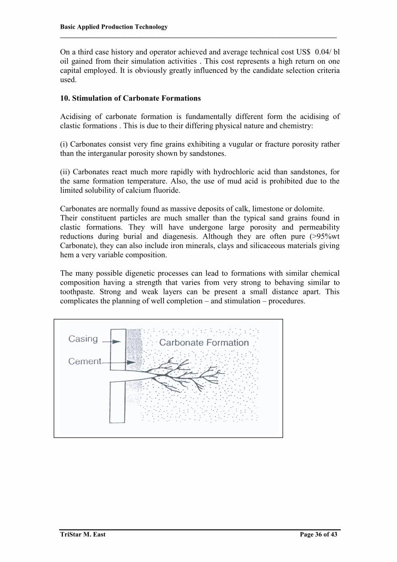
On a third case history and operator achieved and average technical cost US$ 0.04/ bl oil gained from their simulation activities . This cost represents a high return on one capital employed. It is obviously greatly influenced by the candidate selection criteria used. 10. Stimulation of Carbonate Formations Acidising of carbonate formation is fundamentally different form the acidising of clastic formations . This is due to their differing physical nature and chemistry: (i) Carbonates consist very fine grains exhibiting a vugular or fracture porosity rather than the interganular porosity shown by sandstones. (ii) Carbonates react much more rapidly with hydrochloric acid than sandstones, for the same formation temperature. Also, the use of mud acid is prohibited due to the limited solubility of calcium fluoride. Carbonates are normally found as massive deposits of calk, limestone or dolomite. Their constituent particles are much smaller than the typical sand grains found in clastic formations. They will have undergone large porosity and permeability reductions during burial and diagenesis. Although they are often pure (>95%wt Carbonate), they can also include iron minerals, clays and silicaceous materials giving hem a very variable composition. The many possible digenetic processes can lead to formations with similar chemical composition having a strength that varies from very strong to behaving similar to toothpaste. Strong and weak layers can be present a small distance apart. This complicates the planning of well completion – and stimulation – procedures.

Basic Applied Production Technology ___________________________________________________________________________________
TriStar M. East Page 37 of 43
Question – Matrix Stimulation Tutorial
a) Briefly contrast the generalized selection criteria for matrix acidising and fracturing treatments when considering carrying out a stimulation treatment on a well b) List 2sources of formation damage encountered during drilling, completion operations and 3 damage sources during well production. Briefly indicate how the fluid selection for a (matrix) removal treatment will be influenced by the damage source (examples may clarify your answer). c) A well completed on 40 acre spacing) re =745ft) has a damaged region extending 1 ft beyond the wellbore (r w =0.328 ft). The Hawkins formula may be used to calculate may be used to calculate the skin due to formation damage:
Use the above to illustrate the statement: “Formation Damage reduces well productivity greatly while the stimulation effect of increasing the near wellbore permeability above the initial value has limited effect “ HINT estimate the relative well productivity with formation damage (or near wellbore permeability reduction) of 95% 75%, 50% as well as with a stimulated near wellbore formation permeability of 10 times greater than the original value

Basic Applied Production Technology ___________________________________________________________________________________
TriStar M. East Page 38 of 43
Answer –Matrix Stimulation Tutorial
(a)Matrix (Acidsing) –removal of near wellbore damage Hydraulic Fracturing – improving well inflow performance
Skin Permeability Treatment High High Matrix treatment High Medium Matrix / frac and pack High Low Fracturing (matrix possible) Low Low Hydraulic fracturing Low High Treatment economic?
b) Drilling Completion Fluids - solid block pore throats (solids have many sources) - Fluid loss increases liquid saturation - Incompatible formation and fluid loss Production Operation Fluids: scale, wax asphaltenes, fines migration Matrix treatment fluid should dissolve (or at least mobilize) the source of the formation damage, e.g. Wax - hot, organic fluids Calcium carbonate scale - hydrochloric acid Clay particles - mud acid Bonus marks: choice of fluid has to maintain the materials in solution and avoid reprecipitation.
Basic Applied Production Technology ___________________________________________________________________________________
TriStar M. East Page 39 of 43
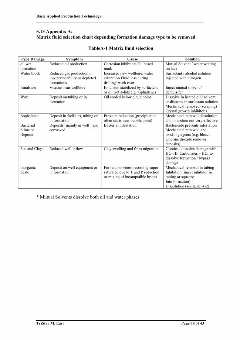
5.13 Appendix A: Matrix fluid selection chart depending formation damage type to be removed
TableA-1 Matrix fluid selection
Type Damage Symptom Cause Solution oil wet formation
Reduced oil production Corrosion inhibitors Oil based mud.
Mutual Solvent / water wetting surface
Water block Reduced gas production in low permeability or depleted formations
Increased new wellbore, water saturation Fluid loss during drilling/ work over
Surfactant / alcohol solution injected with nitrogen
Emulsion Viscous near wellbore Emulsion stabilized by surfactant or oil wet solids e.g. asphaltenes
Inject mutual solvent / demulsifer
Wax Deposit on tubing or in formation
Oil cooled below cloud point Dissolve in heated oil / solvent or disperse in surfactant solution Mechanical removed (scraping) Crystal growth inhibitor s
Asphaltene Deposit in facilities, tubing or in formation
Pressure reduction (precipitation often starts near bubble point)
Mechanical removal dissolution and inhibition not very effective
Bacterial Slime or Deposit
Deposits (mainly in well ) and corrosked
Bacterial infestation Bactericide prevents infestation Mechanical removed and oxidsing agents (e.g. bleach, chlorine dioxide removes deposits)
Sits and Clays Reduced well inflow Clay swelling and fines migration Clastics –dissolve damage with HC/ HF Carbonates – HCI to dissolve formation / bypass damage
Inorganic Scale
Deposit on well equipment or in formation
Formation brines becoming super saturated due to T and P reduction or mixing of incompatible brines
Mechanical removal in tubing Inhibition (inject inhibitor in tubing or squeeze Into formation) Dissolution (see table A-2)
* Mutual Solvents dissolve both oil and water phases
Basic Applied Production Technology ___________________________________________________________________________________
TriStar M. East Page 40 of 43
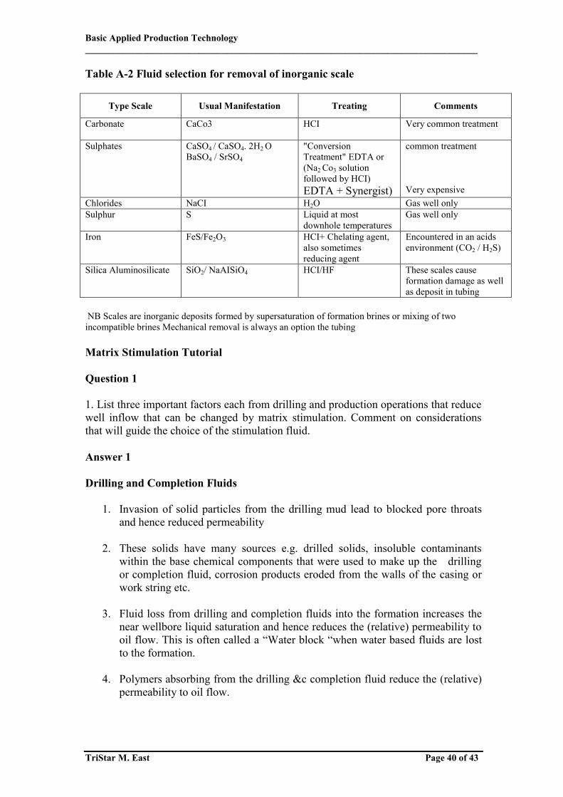
Table A-2 Fluid selection for removal of inorganic scale
Type Scale Usual Manifestation Treating Comments
Carbonate CaCo3 HCI Very common treatment
Sulphates CaSO4 / CaSO4. 2H2 O BaSO4 / SrSO4
"Conversion Treatment" EDTA or (Na2 Co3 solution followed by HCI) EDTA + Synergist)
common treatment Very expensive
Chlorides NaCI H2O Gas well only Sulphur S Liquid at most
downhole temperatures Gas well only
Iron FeS/Fe2O3 HCI+ Chelating agent, also sometimes reducing agent
Encountered in an acids environment (CO2 / H2S)
Silica Aluminosilicate SiO2/ NaAISiO4 HCI/HF These scales cause formation damage as well as deposit in tubing
NB Scales are inorganic deposits formed by supersaturation of formation brines or mixing of two incompatible brines Mechanical removal is always an option the tubing Matrix Stimulation Tutorial Question 1 1. List three important factors each from drilling and production operations that reduce well inflow that can be changed by matrix stimulation. Comment on considerations that will guide the choice of the stimulation fluid. Answer 1 Drilling and Completion Fluids
1. Invasion of solid particles from the drilling mud lead to blocked pore throats and hence reduced permeability
2. These solids have many sources e.g. drilled solids, insoluble contaminants
within the base chemical components that were used to make up the drilling or completion fluid, corrosion products eroded from the walls of the casing or work string etc.
3. Fluid loss from drilling and completion fluids into the formation increases the
near wellbore liquid saturation and hence reduces the (relative) permeability to oil flow. This is often called a “Water block “when water based fluids are lost to the formation.
4. Polymers absorbing from the drilling &c completion fluid reduce the (relative)
permeability to oil flow.

Basic Applied Production Technology ___________________________________________________________________________________
TriStar M. East Page 41 of 43
5. Fluid loss into an formation incompatible with the this fluid leading to clay swelling and reduced permeability
Production Operations: 1. Inorganic scales formed by mixing of incompatible brines within the well or due to precipitation induced by temperature and pressure changes as the brine is produced up the well 2. Wax precipitated from cooling of the oil as isiit produced up the well 3. Asphalting solids precipitated the oil phase due to pressure decreases undergone by the oil as it passes through the production system. 4 4. Fines “(very small diameter particles) that are dislodged by the flow of the produced fluid followed by their migration through the pore spaces. They tend to lodge in the pore throats in the near well bore area. This is because their concentration is highest here due to the nature of radial flow process towards the well. Matrix stimulation fluid selection The matrix stimulation fluid should remove (dissolve, solubilise or at least mobilize the source of the formation damage, e.g. Wax -hot, organic fluids Calcium carbonate scale - hydrochloric acid Clay particles - mud acid “Water block “in a oil well - mutual solvent that solubilises both oil & water phases Bonus marks: choice of fluid has to maintain the materials in solution (avoid reprecipitation of the dissolved solids) and be compatible with the formation. Question 2 You are required to rank the 5 wells in the PetEng field in that order that they should be acidised during the planned well stimulation campaign. You are required to justify your selection in terms of the potential production increase and treatment cost efficiency (US$ per additional BPD oil production capacity). The artificial lift installations each wellhead and surface production faculties have sufficient capacity to cope with the production increases. The completions installed for all the 5 wells is similar with a wellbore radius (rw) of 0.3542 ft and a drainage radius (re) of 8000 ft The full formation height is fully perforated with an interval height (h) of 100ft. The reservoir oil has a viscosity (Uo) of 0.92cp under downhole conditions and the volume shrinkage value during production (Bo) is 1.35bbI/STB. The formation porosity is 33 % and is independent of permeability. The wells were all damaged during the completion phase due to lack of fluid loss control – greater volumes of (damaging) completion fluid were lost into the higher
Basic Applied Production Technology ___________________________________________________________________________________
TriStar M. East Page 42 of 43
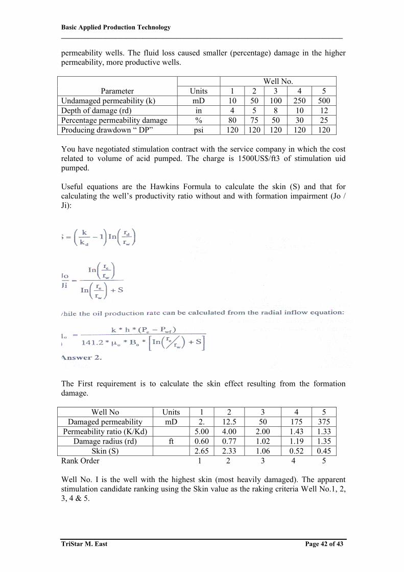
permeability wells. The fluid loss caused smaller (percentage) damage in the higher permeability, more productive wells.
Parameter Well No.
Units 1 2 3 4 5 Undamaged permeability (k) mD 10 50 100 250 500 Depth of damage (rd) in 4 5 8 10 12 Percentage permeability damage % 80 75 50 30 25 Producing drawdown “ DP” psi 120 120 120 120 120 You have negotiated stimulation contract with the service company in which the cost related to volume of acid pumped. The charge is 1500US$/ft3 of stimulation uid pumped. Useful equations are the Hawkins Formula to calculate the skin (S) and that for calculating the well’s productivity ratio without and with formation impairment (Jo / Ji): The First requirement is to calculate the skin effect resulting from the formation damage.
Well No Units 1 2 3 4 5 Damaged permeability mD 2. 12.5 50 175 375
Permeability ratio (K/Kd) 5.00 4.00 2.00 1.43 1.33 Damage radius (rd) ft 0.60 0.77 1.02 1.19 1.35
Skin (S) 2.65 2.33 1.06 0.52 0.45 Rank Order 1 2 3 4 5 Well No. I is the well with the highest skin (most heavily damaged). The apparent stimulation candidate ranking using the Skin value as the raking criteria Well No.1, 2, 3, 4 & 5.

Basic Applied Production Technology ___________________________________________________________________________________
TriStar M. East Page 43 of 43
However, this raking does not take into account that wells show a wide formation permeability rang. The potential production from the wells achieved by removing the damage represents the payback for the stimulation treatment cost: Well No. Units 1 2 3 4 5 Skin (S) 2.65 2.33 1.06 0.52 0.45 Productivity ratio (Jo/Ji) 0.74 0.77 0.88 0.94 0.95 Production rate with damage (Qi) bpd 66 340 799 2.076 4.188 Undamaged Production rate (Qo) bpd 89 433 886 2.215 4.430 Increase in production (Qo-Qi) bpd 23 103 107 139 2420 Rank Order 5 4 3 2 1 It can be seen that the stimulation candidate ranking order is reversed one we base the ranking criteria on the potential gain in production capacity. A different pictures gain if we base the raking criteria on economics, based on the fact that we know the depth of the formation damage and can thus alter the acid treatment size depending on the volume of rock to be treated. Well No Units 1 2 3 4 5 Increase in production (Qo-Qi) bpd 23 103 107 139 242 Volume of removed damage Ft3 109 147 288 404 537 Cost treatment US$ 54.545 73.635 143.997 201.812 268.355 Or US$ per BPD additional production
US$/bpd 2.407 716 1.348 1.448 1.107
Rank Order 5 1 3 4 2 Well No. 2 is now the most attractive stimulation candidate since it minimizes the investment required for the gain in production capacity. This comes about because well no. 2 had a shallow depth of impairment combined with a reasonable production rate response to the removed of the formation damage. The ranking order is quite different from either of the other two quoted above. This criteria is often the best one since the alterative investment is often to drill a new well or to sidetrack an existing well.