Welding Metallurgy of Stainless Steels 12363
12
r.. ! ‘=1 x o - ’ ’ ’ %ll _ %ai .. , L1 Abington Welding Training Module w WELDING METALLURGY OF STAINLESS STEELS 8 r p 5 .lAt ,995 , C Module 22 of the Modular Learning System devised by the Welding Institute of Canada 8 ABINGTON PUBLISHING Woodhead Pubtishmg Ltd m assoctanon WIth The Weldmg Insntute
-
Upload
claudebouillot3566 -
Category
Documents
-
view
65 -
download
9
Transcript of Welding Metallurgy of Stainless Steels 12363
r.. ! ‘=1 x o -
’ ’
’ %ll _ %ai
.. , L1Abington Welding Training Module
wWELDING METALLURGY
OFSTAINLESS STEELS
8
r
p 5 .lAt ,995 ,
C Module 22 of the Modular Learning Systemdevised by the
Welding Institute of Canada
8
ABINGTON PUBLISHINGWoodhead Pubtishmg Ltd m assoctanon WIth The Weldmg Insntute

f
_
Welding Metallurgy of Stainless Steels
x
t/ ,
- ,
11 . w
, ,. i ., PROCEDURES FOR WELDINGSTAINLESS STEEL
There are a number of factors we need to consider when selectinga welding process for stainless steels. First, we recall that chromium
^ hljin 7 ;‘ is highly reactive with oxygen forming a refractory oxide that can be― x.<,,,: difficult to remove. Good shielding of the molten weld pool is
essential to limit contamination by oxygen, and for many applicationsinert gas shielded processes are preferred. Even when shielded metalarc welding is used, additional protection from an inert gas may bedesirable in some applications. When welding from one side, protec-
tion of the reverse side by gas shielding is recommended practice, asFig. 52 illustrates.
GTAW and GMAW with argon or helium/argon mixtures havethe advantage that reactive elements such as aluminum and titaniumare transferred across the arc without significant losses which makesthese processed attractive for alloys of the 321 type.
, / . : ..;: ;,; ;w ;77i , :; ;;··, · ;v Baffles to’
Argon ― B - ;;A; ’ , contain gas, n < ,&dquo;. ’ w:.:fi ;:,·: I
Y7 % %
/B. - t,.:
; F7ufe 52. Typical methods for, back shielding when welding t B / j stainless steel irom one side.
Argon fed throug /
, +
stainless steel from one side.
Argon fed through / ./ gas diffuser tube · ././ / &dquo;B’
/ / / ( ) block with recess)i /X/&dquo;7&dquo;/Bb’ockwithrecess/, When C02 is added to argon base shielding gas for the GMAW’
process, carbon pickup in the weld metal can occur as shown inFig. 53. Caution should be exercised when welding the low carbon
’ grades. Depending on the carbon content of the filler metal, C02 in&dquo;
the shielding gas can increase the weld metal carbon level beyond; 0.03%.i
, Copyright ISBN 1 BS573 173 8 45 No photocopying without permission
t ,
. hfielding Metallurgy of Stainless SteelsWelding Metallurgy of Stainless Steels
Wt% C
- :_ //
0.05 -
_ / / ..... b- //// ia iai/// / iiiiiii Aftar Stenbadca and Persson
t ! t t ) t t t t
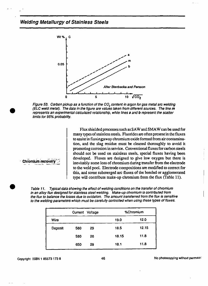
0 5 10 VrCO2Figure 53. Carbon pickup as a function of the CO? content in argon for gas metal arc welding
(ELC weld metal). The data in the figure are values taken from different sources. The line m represents an experimental calculated relationship, while lines a and b represent the scatter
limits for 95% probability.
Flux shielded processes such as SAW and SMAW can be used for
many types of stainless steels. Fluorides are often present in the fluxesto assist in fluxingtaway chromium oxide formed from air contamina- ,
tion, and the slag residue must be cleaned thoroughly to avoid it ’
promoting corrosion in service. Conventional fluxes for carbon steelsshould not be used on stainless steels, special fluxes having been I
homlr.irt ocvljtYA developed. Fluxes are designed to give low oxygen but there is
Chromium mcovery&dquo;,- , inevitably some loss of chromium during transfer from the electrodeto the weld pool. Electrode compositions are modified to correct forthis, and some submerged arc fluxes of the bonded or agglomeratedtype will contribute make-up chromium from the flux (Table 11).
Table 11. Typical data showing the effect of welding conditions on the transfer of chromiumin an alloy flux designed for stainless steel welding. Make-up chromium is contributed fromthe flux to balance the losses due to oxidation. The amount transferred from the flux is sensitiveto the welding parameters which must be carefully controlled when using these types of fluxes.
Current Voltage %Chromium
Wire 19.0 12.0
Deposit 580 29 18.5 12.15
580 26 18.15 11.8
650 29 18.1 I 11.8
Copyright ISBN 1 85573 173 8 46 No photocopying without permisso

,
,
,
Welding Metallurgy of Stainless SteelsI -
SMAWèlèCtrOdes ’ Flux coverings on SMAW electrodes are generally of two types: < . -< ’w .... lime or titania. Table 12 describes the various classifications in AWS
A5.4-92 &dquo;Specification for Stainless Steel Electrodes for ShieldedMetal Arc Welding.&dquo;
Table 12. A WS Specification for Stainless Steel Electrodes for Shielding Metal Arc Welding.
AWS Electrode Current Welding OperatingClassification Coating Type Position Characteristics
EXXX(X)-15 Lime DC All Excellent metallurgical properties
EXXX(X)-16 Titania DC or AC All Good bead profile
EXXX(X)-17 Titania/Silica DC or AC All Fine spray arc with very smooth
bead profile
EXXX(X)-25 Lime DC Horizontal Similar to -15 but core wire mayFlat be mild steel
EXXX(X)-26 Titania DC or AC Horizontal Similar to -16 but core wire mayFlat be mild steel
°&dquo; &dquo; &dquo;’ &dquo; &dquo; Of paramount importance in welding all types of stainless steelsCfeal’l1ng’
- &dquo;&dquo; is the need for cleaning prior to and after welding. The uniquecorrosion properties of the steel may be destroyed by the presence ofcontaminants picked up on the surface during welding operations.Chlorides and other members of the halogen family contribute tostress corrosion cracking and should be avoided. Fluids, such as
8 degreasing agents, machining and cutting fluids should be halogen
free.
Carbon contamination requires careful control, particularly whenwelding the low carbon and ferritic steels, and among the necessaryprecautions are:
. Use stainless steel cleaning brushes
. Use tools reserved for stainless steel
. Use aluminum oxide grinding wheels reserved only forstainless steel
. Carefully clean off grease and dirt before welding
. Do not use electrodes with cellulose in the covering
. Do not use 100% C02 for shielding
Copyright ISBN 1 85573 173 8 47 No photocopying without permission

, I-
; Welding Metallurgy of Stainless Steels I,
-
I ,i pi.tjp yr ; Conventional flame cutting with oxy-acetylene cannot be used<
’ ’ ’ ’&dquo;’ ‘ ‘’r°} .... with stainless steels. Oxy-acetylene flame cutting of steel works not’ by melting the metal but by oxidizing it. The resulting oxide melts and ’
j is removed. The oxidation of iron is retarded by the presence of! chromium in stainless steels which tends to form a solid, high melting(
point oxide. For thermal cutting, either powder cutting or plasma isneeded. In the powder process an iron-rich powder is introduced intothe oxygen stream which accelerates the oxidation reaction facilitat-
ing the cut. Thermally cut weld preparations require machining orgrinding to provide an acceptably clean surface for welding.
The thermal characteristics of austenitic stainless steels permit anarrower groove angle to be used without increasing the risk ofincomplete fusion consistent with proper access. It is common
practice in thick sections to machine a U or J groove preparation thus I,minimizing the amount of filler metal required. Some typical prepa-
rations are shown in Figs. 54,55 and 56. If backing or inserts are usedthey must be of the same alloy as the base metal.
I --1 ---- T Max ’
( ;T
I I .
Up to about 6 mm (0.25 m.)
IT .
60* v Above about 6mm (0.25 in. )
8 2 mm (1/16 in.)
’y-60oy
T 1 Above about 12mm (1/2 in. ) >
3/8 T -1 . T ’ (118 In. )318 T approx. 3mm (1/8 in. )Fgure 54. Typical joint preparations for GTAW in stainless steel.
Copyright ISBN 1 85573 173 8 48 No photocopying without permissic

Welding Metallurgy of Stainless Steels
Although machined preparations allow for excellent fit-up, dis-tortion during welding of stainless steels is higher than for carbonsteels. When welding thin sections, typically less than 6 mm (1/4 in.),good clamping and fixturing is required.
D<ss)mHar ixfetls : Frequently the welding engineer must specify a procedure for ,- ‘ welding dissimilar metals. Joints between stainless steel and carbon
or other steel occur frequently in chemical and power plants, particu-larly in piping where different materials are selected for varioustemperature regimes.
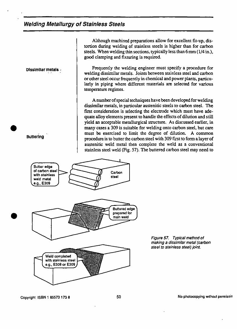
A number of special techniques have been developed for weldingdissimilar metals, in particular austenitic steels to carbon steel. Thefirst consideration is selecting the electrode which must have ade-quate alloy elements present to handle the effects of dilution and stillyield an acceptable metallurgical structure. As discussed earlier, in
many cases a 309 is suitable for welding onto carbon steel, but care, ‘ must be exercised to limit the degree of dilution. A common
BUttenng procedure is to butter the carbon steel with 309 first to form a layer ofaustenitic weld metal then complete the weld as a conventionalstainless steel weld (Fig. 57). The buttered carbon steel may need to
Butter edge r―――of carbon steel t&dquo;---? Carbonwith stainless ’ y&dquo;- T steelweld metal y-i e.g., E309 J ’’&dquo;’
‘‘, vy t ’’’·’ ‘v , Buttered edge
’
‘
°‘
prepared for8 main wetd
«*** Figure 57. Typical method ofmaking a dissimilar metal (carbon
&dquo;’&dquo;-――. steel to stainless steel) joint.
Weld completedwith stainless steel
e.g., E308 or E309 ’
Copyright ISBN 1 85573 173 8 50 No photocopying without parmissio

Welding Metallurgy of Stainless Steels
be stress relieved (tempered) prior to completing the joint. In this waythe carbon steel can be stress relieved without exposing the stainlesssteel to a heat treatment that might sensitize it.
NTh’ , 1 t A further important consideration in selecting a procedure for aThermal stresses dissimilar metal joint is the effect of differences in the physical, dissimilar metal joint is the effect of differences in the physicalproperties. If the properties, particularly the coefficient of thermalexpansion, are greatly different, stresses can be built up in the weld.This is very likely when the joint must enter high temperature service.High stresses can lead to cracking and failure of the joint.
In some cases it is possible to select a weld metal that hasproperties that minimize the build-up of stress. Often weld metal witha coefficient of expansion midway between the two metals is speci-fied. No clear rules can be given because it depends on the alloysbeing welded, service conditions and other constraints, and the
welding engineer must address each case on its own merits. ,
; ’etdtng clad steel It is common practice when designing thick walled vessels to,
specify clad steel rather than solid stainless steel. The thin layer ofstainless cladding provides the necessary corrosion resistance whilethe thick carbon steel provides the mechanical strength. The overallcost can be considerably less. Special techniques, however, arerequired in welding clad steels.
The technique must be designed to ensure freedom from welddefects, correct metallurgical structure, and correct composition of i
the final clad layers that are exposed to the corrosive environment. fSpecial restrictions may be placed on the composition of the exposed Ilayers such as a maximum carbon content, and detailed attention to ,
dilution effects is required. If, for example, we require less than0.03% carbon in the clad layer, and the base steel has 0.2% carbon,
then several buffer layers are needed between the carbon steel and theexposed layer to obtain an adequately low carbon level.
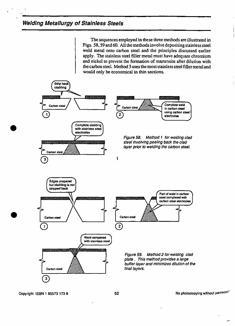
, 7 Bistc ritethod , , There are three basic methods employed for welding clad steel:
Ba$!cMethod$,,,’,, ’ ’
1) Peel back the cladding, complete the joint as though it werea carbon steel then overlay the peeled back region withstainless.
2) Complete part of the joint from the carbon steel side usingcarbon steel electrodes then finish from the clad side usingstainless. I
3) Use stainless weld metal throughout the joint.
Copyright ISBN 1 85573 173 8 51 No photocopying wdhout permission
,

., , 1
Welding Metallurgy of Stainless Steels ’
Weld completed 1 Fgure 60. Method 3 for welding cladwith stainless steel) plate, suitable only for thin material.
Methods 2 and 3 allow more buffer layers of stainless steel
between the carbon steel and the final layers, and these techniquesmay be preferred when very low carbon is specified. Method 2 usesthe least amount of stainless steel filler metal and is the most
economical, but there is a greater risk of the first pass of the carbon ’
steel weld melting through and picking up alloys from the cladding.If this happens cracking is very likely, and the offending pass must becompletely removed before re-welding. When using method 1 or 2 inthick sections a stress relief is sometimes specified after the carbonsteel weld is completed to reduce the risk of cracking when depositingthe stainless weld metal.
!
)Pyright ISBN 1 85573 173 8 53 No photocopying without permission t

. ,
’
Welding Metallurgy of Stainless Steels
Summary
Most of the problems in welding stainless steels arise from basicerrors: incorrect choice of electrodes, for example. Correctly speci-fying a stainless steel welding procedure requires a good comprehen-sion of the underlying metallurgical principles which has been thetopic of this module. We have discussed the effects of nickel andchromium on metallurgical structure, and shown how some elementspromote austenite while others favour ferrite. We described theSchaeffler, DeLong and WRC diagrams which predict weld metalstructure. It was described how these diagrams could be used to selectthe correct composition of an electrode to provide, for example,
adequate 8 ferrite to avoid hot cracking. We discussed sensitization,stress corrosion cracking, and the consequences of chromium oxida-tion. The main features of welding procedures for austenitic, ferritic,and martensitic steels, and dissimilar metal joints were introduced.
Having sucessfully completed this module you will be able torecognize potential metallurgical problems in welding stainless steelsand select the main features of a welding procedure to successfullyweld them. It is recommended, however, that you consult the supplierand other resources for exact details for welding specific alloys.
8
Copyright ISBN 1 85573 173 8 54 No photocopyng without permission
. i
.....
. ’ Welding Metallurgy of Stainless Steels
&dquo; :1
,
I
Additional ResourcesI
Below is a short list of additional sources of information that may Bhelp you in your study of the Welding Metallurgy of Stainless Steels.
1. Welding aspects are covered in: i
Welding Handbook, Seventh Edition, Vol. 4American Welding Society, 550 N.W. LcJeune Road,Miami, FL 33126, U.S.A.
Metals Handbook, Tenth Edition, Vol. 6
American Society for Metals, Metals Park, Ohio 44073, U.S.A. ’
Welding of Stainless Steels and other Joining Methods1979 American Iron and Steel Institute, 1000 16th StreetN.W. Washington, DC., U.S.A.
2. There is an extensive literature covering cracking and ferrite instainless steel weld metals. This was the topic of the 1974Adams Lecture:
. Ferrite in Austenitic Stainless Steel Weld Metal,by W. T. DeLong, Welding Journal Research Supplement,July 1974 pp 273-s to 286-s.
’
Diagrams for predicting stainless steel weld metal structure have
been reviewed by Olsen:
. Prediction of Austenitic Weld Metal Microstructure andProperties, D. L. Olsen, Welding Journal ResearchSupplement, October 1985 pp 281-s to 295-s.
3. For information on welding specific alloys you should contactthe various suppliers.
’yright ISBN 1 85573 173 8 55 No photocopying without permission
=