Welding and Heat Treatment Steel industry · 2014-11-05 · Crack propagates under the effect of...
50
Copyright © ESI Group, 2009. All rights reserved. 1 Welding and Heat Treatment in Steel industry Modeling Techniques and Applications Philippe MOURGUE ESI-France 16 October 2014
Transcript of Welding and Heat Treatment Steel industry · 2014-11-05 · Crack propagates under the effect of...

Copyright © ESI Group, 2009. All rights reserved. 1
Welding and Heat Treatment
in
Steel industry
Modeling Techniques and Applications
Philippe MOURGUE ESI-France
16 October 2014

Copyright © ESI Group, 2009. All rights reserved. 2
AGENDA
STEEL Material - Metallurgy
Heat Treatment application
Welding application

Copyright © ESI Group, 2009. All rights reserved.
distorsion history during quenching period
Quenching of a gear
WHY SUCH BEHAVIOR ?

Copyright © ESI Group, 2009. All rights reserved.
Thermal & MetallurgicalProperties
Thermal properties versus to temperature (T°c) and according to the considered phases (zi)
Thermal conductivity : = f(T°c, zi)
Density : = f(T°c, zi)
Specific heat : Cp = f(T°c, zi)
Enthalpy : H = f(T°c, zi)
Latent Heat Effect : H = f(T°c, zi)
Metallurgical Kinetics of Transformation for different heating and cooling rate
Austenitic Transformation : Z = f(T °c, dT/dt)
Ferrite Transformation : Zf = f(T °c, dT/dt)
Bainite Transformation : Zb = f(T °c, dT/dt)
Martensite Transformation : Zm = f(T °c)

Copyright © ESI Group, 2009. All rights reserved.
MODELISATION
CCT Diagram Transformations de phase (acier)
Evolution d’état
-0,4
0
0,4
0,8
1,2
1,6
0 400 800
Température [°C]
Défo
rmati
on [
%]
Phase
Phase
Body-centered
cubic
Face-centered
cubic
Austenite Transformation
Martensite Transformation
Cooling Rate
dT/dt = -15°C/s
-0,4
0
0,4
0,8
1,2
1,6
0 400 800
Température [°C]
Défo
rmati
on [
%]
Phase
Phase
Body-centered
cubic
Face-centered
cubic
Austenite Transformation
Martensite Transformation
Cooling Rate
dT/dt = -15°C/s
Yield Stress vs
Temperature
for each phases.

Copyright © ESI Group, 2009. All rights reserved.
Mechanical Properties
Mechanical properties versus to temperature (T°c) and
according to the considered phases (zi) Young’s modulus : E = f(T°c, zi)
Poisson coefficient : = f(T°c, zi)
Thermal strains : th = f(T°c, zi)
Yield stress : = f(T°c, zi)
Strain hardening : h = f(T°c, zi)
Viscous parameter
Hardening Coefficient : K = f(T°c, zi)
Hardening Exponent : m = f(T°c, zi)
Strain Rate Sensitive Exponent : n = f(T°c, zi)

Copyright © ESI Group, 2009. All rights reserved.
MODELES PHYSIQUE
SYSWELD permet un couplage fort entre la Thermique
et la Métallurgie
Diffusion - Précipitations
Electromagnétisme
Analyses Mécaniques
Analyse Thermique
Metallurgie
Dissipated Joule Energy
Temperatures
Temperatures Temperatures Phase Proportions
Temperatures Latent Heat Phase Proportions
Chemical Composition Precipitations
Chemical Composition Precipitations
Deformation- energy
Stresses

Copyright © ESI Group, 2009. All rights reserved.
METALLURGICAL PHENOMENON
Température
Transformation Martensitique
Transformation Bainitique
Transformation Austénitique
Déformations
Contraintes

Copyright © ESI Group, 2009. All rights reserved.
HEAT TREATMENT APPLICATIONS
9

Copyright © ESI Group, 2009. All rights reserved.
distorsion history during quenching period
Quenching of a gear

Copyright © ESI Group, 2009. All rights reserved.
Nozzle HyperQuench
Objectives: Residual stresses and deformation after
treament, machining and structural analysis

Copyright © ESI Group, 2009. All rights reserved.
Thermal evolution during HT
Nozzle Hypertremp
Von mises stress after HT and Machining

Copyright © ESI Group, 2009. All rights reserved.
Stresses at skin: Mesures Simulation
Nozzle HyperQuench

Copyright © ESI Group, 2009. All rights reserved.
WELDING APPLICATIONS
14

Copyright © ESI Group, 2009. All rights reserved. 15
Transient Welding Modeling
Heat source adjustment
0
200
400
600
800
1000
1200
1400
0 1 2 3 4 5 6 7
Position (mm)
tem
pera
ture
(°C
)
Experiment
Simulation
Copyright © ESI Group, 2009. All rights reserved. 16
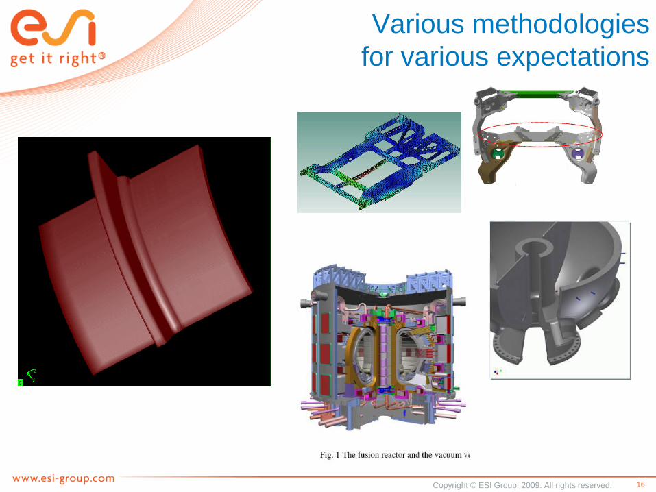
Various methodologies
for various expectations

Copyright © ESI Group, 2009. All rights reserved. 17
Transient Welding Modeling
Single Pass process
1: Transient temperature field
2: Final distortion
3: Residual stresses
1
3
2

Copyright © ESI Group, 2009. All rights reserved. 18
Transient Welding Modeling
A more complex welding sequence
Distortion

Copyright © ESI Group, 2009. All rights reserved. 19
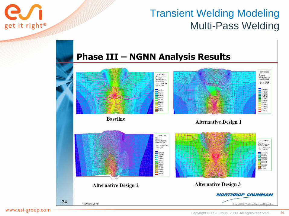
Transient Welding Modeling
Multi-Pass Welding
Temperature
Distortion

Copyright © ESI Group, 2009. All rights reserved. 20
Multi pass welding:
Thermal /metallurgical
/mechanical analysis
Thermal analysis
during each of the 30
welding pass taking
into account
convection and
radiation
Stress analysis during
welding sequences
Nozzle repair
Residual stress analysis
Drain/ Instrumentation Nozzle
Predifined Goldak heat source
SYSWELD Courtesy Doosan
20
Realistic ‘as-built’ model

Copyright © ESI Group, 2009. All rights reserved. 21
Heat treatment:
Heat convection and
radiation
Stress released after
Post Weld Heat
Treatment (PWHT)
Nozzle repair
Residual stress analysis
SYSWELD
Courtesy Doosan
21

Copyright © ESI Group, 2009. All rights reserved. 22
Copyright © ESI Group, 2009. All rights reserved. 23

Copyright © ESI Group, 2009. All rights reserved. 24
CTC
24
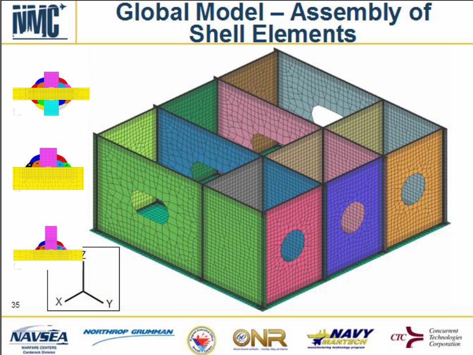
Examples & proofs from ship building (CTC) & railway (Maglev)
Tool
bars
Output
Console
Original position
Measured distortion
Predicted distortion
Distorted Structure SYSWELD Predictions Validation Plot
Example of Shipbuilding Application (Courtesy CTC)

Copyright © ESI Group, 2009. All rights reserved. 25
ITER: Local-Global

Copyright © ESI Group, 2009. All rights reserved. 26

Copyright © ESI Group, 2009. All rights reserved. 27

Copyright © ESI Group, 2009. All rights reserved. 28
Welding simulation for
Process optimisation
Stamping, Heat Treatment and Welding
Huge Thick Walled Designs
Copyright © ESI Group, 2009. All rights reserved. 29
Transient Welding Modeling
Multi-Pass Welding

Copyright © ESI Group, 2009. All rights reserved. 31
ITER Vacuum Vessel Welding
ITER project – Vacuum vessel electron beam welding assembly
1 of the 9 sectors of the ITER vacuum vessel
VEC mock-up
Rolling the inner and outer shell
Machining the housing holes
Welding the components together SYSWELD
31

Copyright © ESI Group, 2009. All rights reserved. 32
Distortion validation
Key welding results
Circular EB welds
32

Copyright © ESI Group, 2009. All rights reserved. 33
Clamping effects

Copyright © ESI Group, 2009. All rights reserved. 34
Clamping effects

Copyright © ESI Group, 2009. All rights reserved. 35
Fatigue life
Courtesy PSA
Congres NAFEM France – 12 Octobre 2010

Copyright © ESI Group, 2009. All rights reserved. 36

Copyright © ESI Group, 2009. All rights reserved. 37

Copyright © ESI Group, 2009. All rights reserved. 38

Copyright © ESI Group, 2009. All rights reserved. 39

Copyright © ESI Group, 2009. All rights reserved. 40

Copyright © ESI Group, 2009. All rights reserved. 41
Cold cracking
Hydrogen impact

Copyright © ESI Group, 2009. All rights reserved. 42
Cold cracking
Welding of a Dissimilar weld
Electron beam process
Hydrogen diffusion
Crack initiation and propagation
3 Materials + molten zone
MATERIAL_1
MATERIAL_3
MATERIAL_2
Case study :
•26 months in storage conditions
•Pressure test
Initial H content

Copyright © ESI Group, 2009. All rights reserved. 43
Welding simulation
3D axial symmetric model By Steady state method on 340 degrees
By a transient method to simulate the end of welding

Copyright © ESI Group, 2009. All rights reserved. 44
Welding simulation 3D
By a transient method to simulate the weld recovery
area (3 degrees)
3°

Copyright © ESI Group, 2009. All rights reserved. 45
Mechanical results
Slope area Hoops stresses
Crack opening stress

Copyright © ESI Group, 2009. All rights reserved. 46 46
Hydrogen concentration
Cumulative plastic strain
Iso H2 concentration after
welding and 1 during year
storage
Initial H2
content
H2 properties depend on
Température and Plastic
Strains
Hydrogen diffusion

Copyright © ESI Group, 2009. All rights reserved. 47
Crack propagation
26 months In storage conditions
Crack propagates under the effect of welding residual stresses
and hydrogen embrittlement
a = 0 if J ≤ Jc kJ/m²
a = 0.5 mm where J = Jmax along the front
Ho
op
str
esses
Cu
mu
lati
ve
pla
sti
c s
tra
ins
H1
H2
a
J
Plastic strains developed at the
crack front

Copyright © ESI Group, 2009. All rights reserved. 48
Crack propagation
In storage conditions
Crack propagates under the effect of welding residual
stresses and hydrogen embrittlement
Compressive
hoop stresses
Decreasing
tensile
hoop
stresses
From 0 to 26 months

Copyright © ESI Group, 2009. All rights reserved. 49
Crack propagation
Hydro test simulation
Predicted crack
front
The wall is now
perforated

Copyright © ESI Group, 2009. All rights reserved. 50
Couple mechanical results and hydrogen diffusion to capture the crack
propagation kinetic
Requires a better characterization of H diffusion to consider trapping effect
3D modeling of H diffusion and averaging of values in the first ring of elements
could be done in order to smooth numerical singularity
Possibility to check the stability of an open crack
Simulation of the pressure test with a crack open
Simulate the same crack behavior in real flight conditions
Requires the definition of flight loads
Do not require any new material characterization as the crack tip is out of the HAZ
Conclusions
Delivered Value

Copyright © ESI Group, 2009. All rights reserved. 51
Thank You
You
Product, processes, knowledge, engineering
Simulation
Helps to improve engineering
You & Simulation Engineering
Cost reduction & Quality improvement
Simulation makes engineering more transparent