Weld County Engineering and Construction … County Engineering and Construction Guidelines ... 1.4...
99
Weld County Engineering and Construction Guidelines April 2012 Updated July 2017
Transcript of Weld County Engineering and Construction … County Engineering and Construction Guidelines ... 1.4...
Weld County Engineering
and Construction Guidelines
April 2012Updated July 2017
WELD COUNTY ENGINEERING & CONSTRUCTION GUIDELINES P a g e | i
TABLE OF CONTENTS
Chapter 1 – GENERAL PROVISIONS ............................................................................................................................1
1.1 Title .........................................................................................................................................................1
1.2 Purpose and Background ........................................................................................................................1
1.3 Applicability ............................................................................................................................................1
1.4 Reference Documents.............................................................................................................................1
1.5 Interpretation .........................................................................................................................................2
1.6 Road Acceptance ....................................................................................................................................2
1.7 Improvements and Reimbursement Agreements ..................................................................................2
Chapter 2 – ROAD CLASSIFICATIONS AND TYPICAL SECTIONS ...................................................................................4
2.1 Road Classification System .....................................................................................................................4
2.2 Typical Cross Sections .............................................................................................................................5
2.3 Alternative Design Approval ................................................................................................................ 16
Chapter 3 – SURVEYING AND RIGHT-OF-WAY ......................................................................................................... 17
3.1 Right-of-Way Widths ............................................................................................................................ 17
3.2 Right-of-Way Use Permits .................................................................................................................... 17
3.3 Right-of-Way Determination ............................................................................................................... 17
3.4 Survey Data .......................................................................................................................................... 17
3.5 State Plane ........................................................................................................................................... 17
3.6 Monument Boxes ................................................................................................................................. 18
3.7 Road Safety .......................................................................................................................................... 18
3.8 Right-of-Way Acquisitions.................................................................................................................... 18
Chapter 4 – ROADWAY DESIGN GUIDELINES .......................................................................................................... 19
4.1 General ................................................................................................................................................. 19
4.2 Horizontal Alignment ........................................................................................................................... 21
4.3 Vertical Alignment ............................................................................................................................... 22
WELD COUNTY ENGINEERING & CONSTRUCTION GUIDELINES P a g e | ii
4.4 Sight Distance....................................................................................................................................... 23
4.5 Intersections ........................................................................................................................................ 28
4.6 Cul-de-Sacs ........................................................................................................................................... 29
4.7 Bridges ................................................................................................................................................. 29
4.8 Alternative Design Approval ................................................................................................................ 31
Chapter 5 – DRAINAGE CRITERIA............................................................................................................................. 33
5.1 Drainage Policy .................................................................................................................................... 33
5.2 Drainage Law........................................................................................................................................ 33
5.3 Submittal Criteria ................................................................................................................................. 34
5.4 Rainfall ................................................................................................................................................. 35
5.5 Runoff................................................................................................................................................... 37
5.6 Street Drainage .................................................................................................................................... 37
5.7 Major Drainage .................................................................................................................................... 38
5.8 Minor Drainage .................................................................................................................................... 38
5.9 Hydraulic Structures............................................................................................................................. 39
5.10 Culverts ................................................................................................................................................ 40
5.11 Storage ................................................................................................................................................. 42
5.12 Revegetation ........................................................................................................................................ 43
5.13 Stormwater Quality/MS4 Requirements ............................................................................................. 44
5.14 Best Management Practices ................................................................................................................ 46
5.15 FEMA Floodplain Requirements .......................................................................................................... 46
Chapter 6 – TRAFFIC CRITERIA ................................................................................................................................. 48
6.1 Traffic Impact Studies .......................................................................................................................... 48
6.2 Traffic Control Devices and Plans ........................................................................................................ 49
6.3 Access Control Plan .............................................................................................................................. 50
6.4 Access Design ....................................................................................................................................... 51
6.5 Access Sight Distance ........................................................................................................................... 52
WELD COUNTY ENGINEERING & CONSTRUCTION GUIDELINES P a g e | iii
6.6 Auxiliary Turn Lanes ............................................................................................................................. 57
6.7 Access Construction ............................................................................................................................. 60
6.8 Change in Access Use ........................................................................................................................... 61
6.9 Temporary Access ................................................................................................................................ 61
6.10 Tracking Control ................................................................................................................................... 61
Chapter 7 – SOIL INVESTIGATION AND PAVEMENT DESIGN ................................................................................... 63
7.1 Introduction and Purpose .................................................................................................................... 63
7.2 Field Investigation and Soil Samples .................................................................................................... 63
7.3 Subgrade Testing.................................................................................................................................. 63
7.4 Pavement Design Criteria .................................................................................................................... 65
7.5 Flexible Pavement Design .................................................................................................................... 67
7.6 Material Specification .......................................................................................................................... 70
7.7 Soils/Pavement Design Report ............................................................................................................ 71
7.8 Alternative Design Approval ................................................................................................................ 72
Chapter 8 – CONSTRUCTION GUIDELINES ............................................................................................................... 73
8.1 General ................................................................................................................................................. 73
8.2 Contractor Responsibilities .................................................................................................................. 74
8.3 Materials Quality Control and Testing ................................................................................................. 79
8.4 Excavation and Embankment .............................................................................................................. 81
8.5 Subgrade Construction Methods ......................................................................................................... 82
8.6 Base Course Construction Methods .................................................................................................... 84
8.7 Pavement Construction Methods ........................................................................................................ 86
8.8 Structures and Drainage Features ....................................................................................................... 88
8.9 Other Roadway Features ..................................................................................................................... 89
8.10 Alternative Design Approval ................................................................................................................ 91
Chapter 9 – PERMITTING ......................................................................................................................................... 93
9.1 Special Transport Permit ...................................................................................................................... 93
WELD COUNTY ENGINEERING & CONSTRUCTION GUIDELINES P a g e | iv
9.2 Right-of-Way Permit ............................................................................................................................ 93
9.3 Access Permit ....................................................................................................................................... 93
9.4 Grading Permit ..................................................................................................................................... 93
9.5 Flood Hazard Permit ............................................................................................................................ 93
9.6 Geohazard Permit ................................................................................................................................ 94
9.7 Memorial Sign Applications ................................................................................................................. 94

WELD COUNTY ENGINEERING & CONSTRUCTION GUIDELINES P a g e | 1
CHAPTER 1 – GENERAL PROVISIONS
1.1 TITLE
This manual is called the Weld County Engineering & Construction Guidelines and shall be referred to
throughout the text as the WCECG.
1.2 PURPOSE AND BACKGROUND
Communities and counties often provide engineering criteria for the repair and construction of
infrastructure, outlining specific “must build” requirements. In Weld County, which covers 4,000 square
miles, the range of soil types and site conditions is such that it is not practical or advisable to develop
such specific requirements. In Weld County, one size does not fit all.
However, recognizing the need in the engineering community for basic information about the County’s
criteria for acceptable infrastructure, the County has developed this document. It outlines design and
material options and guidelines for the design, construction, location, improvement, and maintenance
of infrastructure in Weld County.
The guidelines outlined in this manual are intended to provide the designer with choices that will
facilitate the development of infrastructure that is well suited to County needs and is safe, efficient, and
economical. They reflect the use of both accepted and new technologies. However, some cases may
arise where alternatives to these guidelines will be more cost effective, better achieve project goals, or
more easily accommodate existing conditions. In such cases, requests for alternatives to these
guidelines will be considered. The procedures to request alternative designs are detailed in each
chapter. The overriding requirement is that all improvements must be designed and constructed with
professional integrity and quality at the forefront.
1.3 APPLICABILITY
The WCECG applies to all lot dividers, developers, landowners, and owners of facilities adjacent to or
located in the County’s rights-of-way or easements, and to the employees, agents, or contractors of
these entities, when they design, construct, and maintain facilities or conduct other activities subject to
review and approval under the provisions of the Weld County Code. The WCECG also applies to the
County and its employees, agents, and contractors.
1.4 REFERENCE DOCUMENTS
The WCECG hereby adopts the latest versions of the following documents by reference.
• American Association of State Highway and Transportation Officials (AASHTO) A Policy on Geometric
Design of Highways and Streets
• AASHTO Guide for Design of Pavement Structures
• AASHTO Roadside Design Guide
• AASHTO Standard Specifications for Transportation Materials and Methods of Sampling and Testing
• AASHTO Standard Specifications for Highway Bridges
WELD COUNTY ENGINEERING & CONSTRUCTION GUIDELINES P a g e | 2
• AASHTO Load & Resistance Factor Design (LRFD) Bridge Design Specifications
• AASHTO LRFD Bridge Construction Specifications
• American Society for Testing Materials (ASTM) “Annual Book”
• Colorado Department of Transportation (CDOT) Access Control Plans
• CDOT Bridge Design Manual
• CDOT Construction Manual
• CDOT Field Materials Manual
• CDOT M & S Standard Plans
• CDOT Roadway Design Guide
• CDOT Standard Specifications for Road and Bridge Construction
• Colorado Revised Statutes
• Relevant Federal Emergency Management Agency (FEMA) documents
• Federal Highway Administration (FHWA) Manual on Uniform Traffic Control Devices (MUTCD)
• FHWA Roundabout Design Guidelines (FHWA-RD-00-067)
• FHWA Railroad/Highway Crossing Grade Handbook
• FHWA Real Estate Acquisition Guide for Local Public Agencies (“The Uniform Act”)
• Institute of Transportation Engineers (ITE) Trip Generation Manual
• Urban Drainage and Flood Control District (UDFCD) Urban Storm Drainage Criteria Manual (Volumes 1,
2, and 3)
• Weld County Code
• Weld County Transportation Plan
1.5 INTERPRETATION
This manual presents the basic guidelines that must be met to ensure that infrastructure facilities are
safe, efficient, economical, and appropriate for use in the County. Where minimum values are stated,
greater values for safety, durability, or functional limits are encouraged whenever practical and
consistent with federal, state, and local requirements. Situations might arise where the application of
individual guidelines from the WCECG will not ensure the protection of public health, safety, and
welfare. Accordingly, Weld County may choose not to accept the infrastructure for taxpayer-funded
maintenance; may impose additional or more stringent criteria than those contained in the WCECG; or
may require the modification of plans, specifications, or operations to protect public health, safety, and
welfare.
1.6 ROAD ACCEPTANCE
Acceptance of a road for maintenance by the County is at the discretion of the BOCC and requires
passage of a resolution. The Weld County Road Acceptance Policy requirements are available in Sections
8-6-40 and 8-6-150 of the Weld County Code.
1.7 IMPROVEMENTS AND REIMBURSEMENT AGREEMENTS
Final plats require the developer to sign an improvements agreement with the County and provide
collateral to guarantee the improvements are completed as required. The agreement also gives the

WELD COUNTY ENGINEERING & CONSTRUCTION GUIDELINES P a g e | 3
developer the opportunity to be reimbursed by a subsequent development that uses the original
developer’s road improvements. See Section 24-9-20 of the Weld County Code for more information.
WELD COUNTY ENGINEERING & CONSTRUCTION GUIDELINES P a g e | 4
CHAPTER 2– ROAD CLASSIFICATIONS AND TYPICAL SECTIONS
2.1 ROAD CLASSIFICATION SYSTEM
The County classifies roadways based on their function and whether they are urban or rural. These two
classifications help designers determine the appropriate design characteristics for the road, including
cross section and geometric standards. The functional classifications and urban/rural classification take
into account anticipated traffic volume and access requirements on a road and determine the minimum
right-of-way required. Together, these classifications help determine the minimum level of service (LOS).
They are a rational, cost-effective basis for the selection of geometric criteria within the range of values
available to the designer.
The BOCC adopts a Road Classification Map by ordinance and reviews it every two years. Changes made
between the two-year reviews are typically based on development reviews, and are made on a case-by-
case basis via a public hearing process. The current Weld County Functional Classification Map can be
found on the Transportation Plan web page under Public Works Department’s Transportation Planning
web page. In addition, the Weld County Transportation Plan includes recommendations for when to
modify road classifications.
2.1.1 Functional Classifications
Function is determined based on the degree to which a roadway provides access and allows mobility.
Roadways provide access when they allow travelers to easily reach most of the destinations within a
given area. Roadways provide mobility when they allow travelers to easily go longer distances.
The classification of Weld County roads is comprised of a hierarchy of roadways whose functional
classifications are defined by their usage. The relative degree to which a road serves these functions
defines its functional classification. Roads in Weld County are classified as Arterial, Collector, Local, or
Private Roads. The functional classifications of roadways used by Weld County are as follows.
• Freeways (Interstates). Freeways usually provide the greatest mobility, allowing long-distance travel
between communities. Access is allowed only at interchanges. No direct property access is allowed.
Other state highways may be considered arterials or collectors by CDOT.
• County Highway. A county highway is a four-lane controlled-access arterial road, the construction of
which commenced in 2016, intersecting with an interstate highway or a United States numbered
highway. Roads that were annexed before the county’s designation of the road as a county highway may
also be included by intergovernmental agreement with the municipality. Weld County has designated
Weld County Road 49 between I-76 and US 34, the Weld County Parkway, and Weld County Road 47
from the Parkway to State Highway 392 as a county highway. See the Weld County Functional
Classification Map, available on the County’s Transportation Planning webpage. The county highway
designation means Weld County will govern all substantive aspects of the road, including access,
maintenance, traffic control, speed limits, and overweight limits, even if municipalities later annex the
road.
• Arterials. Arterials provide good mobility, carrying significant traffic volumes at high speeds for long
distances. They are seldom spaced at closer than one-mile intervals and serve to connect larger

WELD COUNTY ENGINEERING & CONSTRUCTION GUIDELINES P a g e | 5
communities. The primary difference between freeways and major arterials is access. Freeways have
fully controlled accesses with no at-grade intersections, while arterials include limited at-grade
intersections.
• Collectors. Collectors link local roads with the arterial road system and connect smaller communities.
Both mobility and access are of equal importance on these roadways. Travel speeds and volumes are
moderate, and distances traveled are short to medium. Traffic on collector roads typically has an origin
or destination within the nearby area. Weld County has both paved and unpaved collector roads.
• Local roads. Local roads primarily provide access to adjacent land in rural and urban areas. Local roads
are closely spaced and carry relatively lower traffic volumes for short distances. They generally are
internal to—or serve an access function for—a residence, farm, single neighborhood, or development.
Generally, they should lead traffic to a collector road.
• Privately maintained roads. Weld County may review privately maintained roads that are planned to be
used by the public, such as a road within the boundaries of a residential subdivision, but the roads shall
be maintained by a homeowner’s association (HOA) or other private entity.
2.1.2 Urban and Rural Classifications
In addition to classifying roads by function, the Weld County Transportation Plan classifies roads as
Urban or Rural.
Urban roads usually serve more developed areas and diverse uses (e.g., bicyclists, pedestrians, on-street
parking, etc.). Urban roads are usually paved, with curbs, gutters, and sidewalks. Often, they connect to
an existing stormwater drainage system rather than making use of roadside ditches (which are
commonly found beside rural roads).
Rural roads primarily serve less developed areas and lower volumes of vehicular traffic. The majority of
the roads in Weld County are classified as rural. However, roads which are in Urban Growth Boundaries
may be classified as urban.
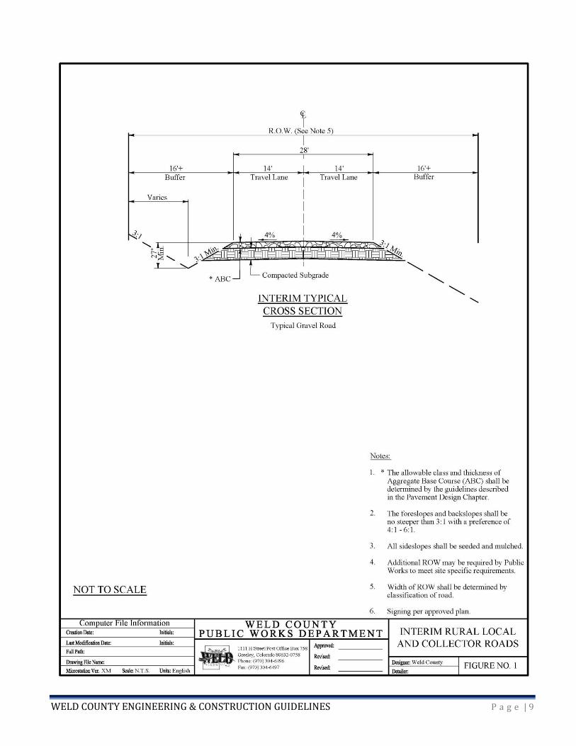
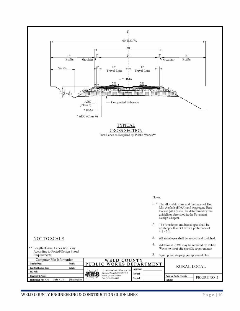
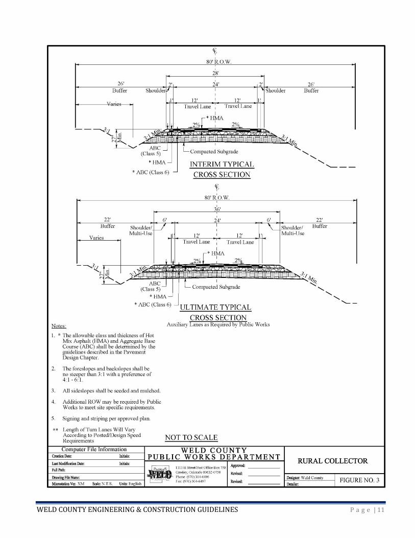
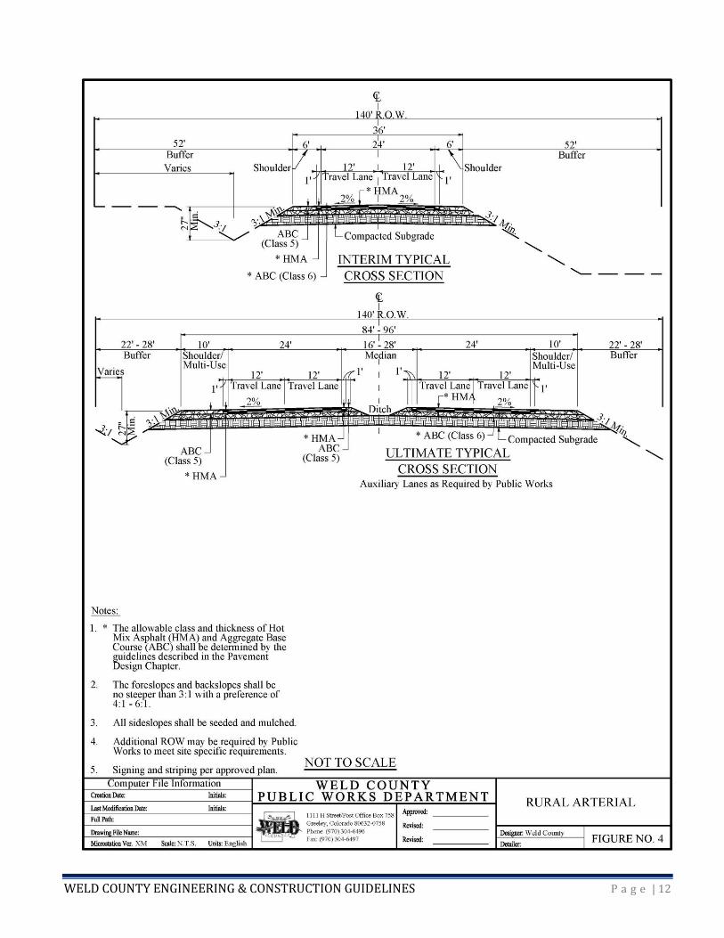
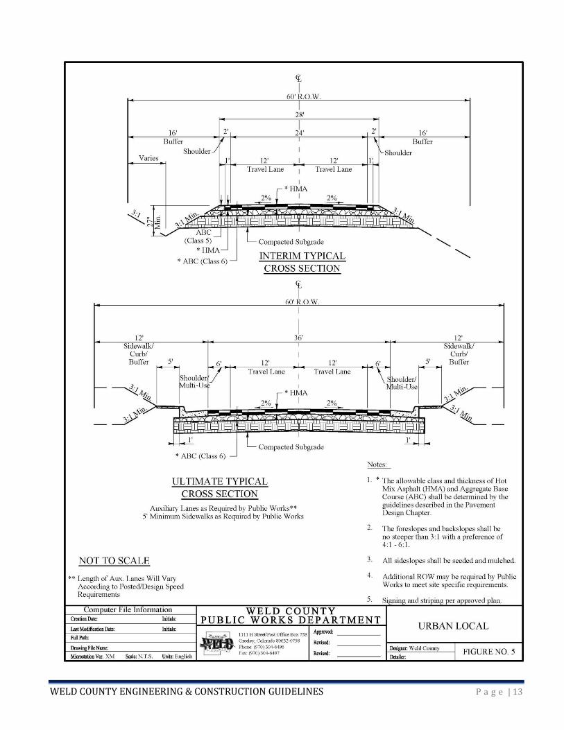
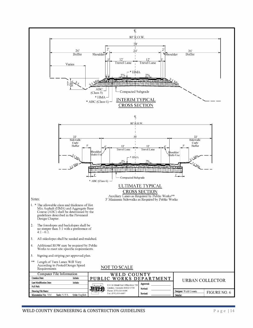
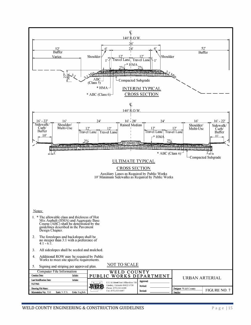
2.2 TYPICAL CROSS SECTIONS
While it is important to try to preserve the ultimate right-of-way, funding availability does not always
allow for construction of the ultimate section, and in such cases an interim section should be
constructed until funding becomes available.
The Public Works Department determines whether a road is designed to the interim or ultimate (or
combinations thereof) road cross section. This determination is based on funding, existing and projected
traffic volumes, connectivity, continuity, mobility, and capacity. If only a portion of the ultimate cross
section is being constructed, the interim design will need to allow for eventual widening of the road to
the ultimate cross section. The interim design should ensure that the first phase of the roadway will not
need to be removed to complete the full cross section.
All designs should take into account how the roadway is used, long-term traffic predictions, location and
density of nearby development, and topographical characteristics. A roadway constructed to the
ultimate cross section may still require more right-of-way and roadway width in the future for additional
lanes, pedestrian or bicycle facilities, landscaping, utilities, or construction requirements such as cut or

WELD COUNTY ENGINEERING & CONSTRUCTION GUIDELINES P a g e | 6
fill slopes. Designers should try to anticipate such needs. Other chapters within this manual will discuss
design considerations in more detail.
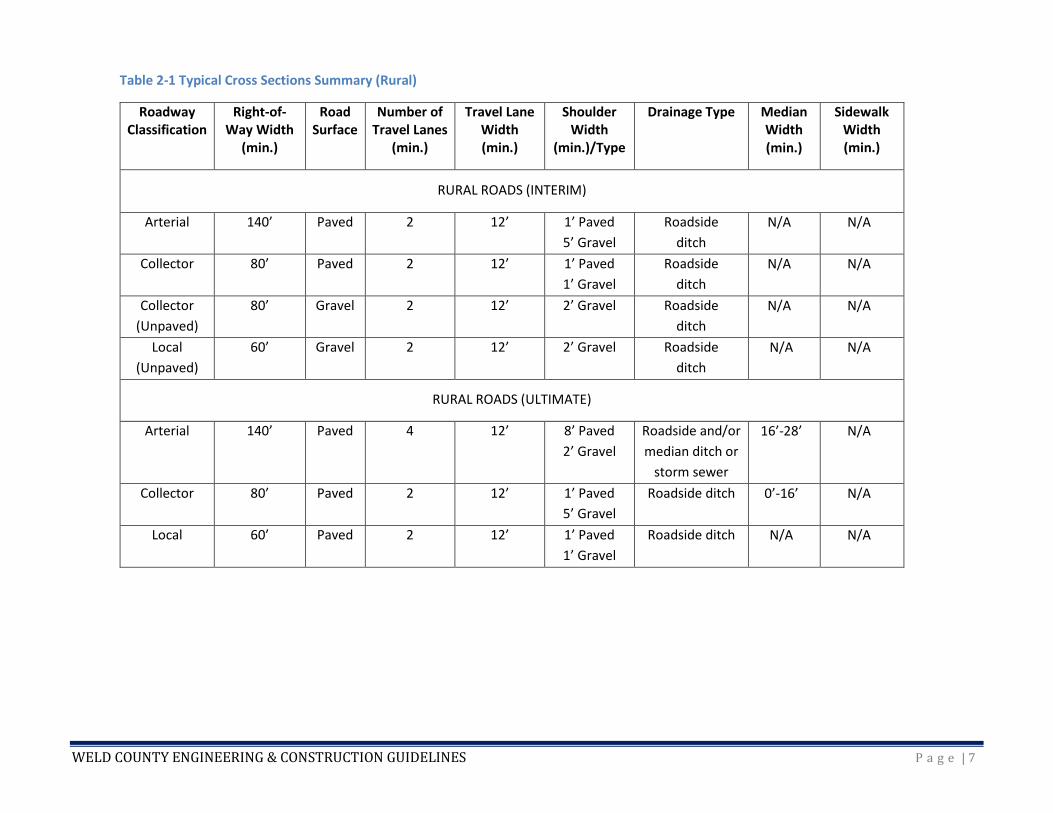
Table 2-1 (Rural Conditions) and Table 2-2 (Urban Conditions) summarize some of the features
incorporated into the typical cross section drawings for the different road classifications. It should be
noted that the tables and typical sections in this manual usually reflect minimum requirements. The
Public Works Department may impose additional requirements on a case-by-case basis.
WELD COUNTY ENGINEERING & CONSTRUCTION GUIDELINES P a g e | 7
Table 2-1 Typical Cross Sections Summary (Rural)
Roadway Classification
Right-of-Way Width
(min.)
Road Surface
Number of Travel Lanes
(min.)
Travel Lane Width (min.)
Shoulder Width
(min.)/Type
Drainage Type Median Width (min.)
Sidewalk Width (min.)
RURAL ROADS (INTERIM)
Arterial 140’ Paved 2 12’ 1’ Paved
5’ Gravel
Roadside
ditch
N/A N/A
Collector 80’ Paved 2 12’ 1’ Paved
1’ Gravel
Roadside
ditch
N/A N/A
Collector
(Unpaved)
80’ Gravel 2 12’ 2’ Gravel Roadside
ditch
N/A N/A
Local
(Unpaved)
60’ Gravel 2 12’ 2’ Gravel Roadside
ditch
N/A N/A
RURAL ROADS (ULTIMATE)
Arterial 140’ Paved 4 12’ 8’ Paved
2’ Gravel
Roadside and/or
median ditch or
storm sewer
16’-28’ N/A
Collector 80’ Paved 2 12’ 1’ Paved
5’ Gravel
Roadside ditch 0’-16’ N/A
Local 60’ Paved 2 12’ 1’ Paved
1’ Gravel
Roadside ditch N/A N/A

WELD COUNTY ENGINEERING & CONSTRUCTION GUIDELINES P a g e | 8
Table 2-2 Typical Cross Sections Summary (Urban)
Roadway Classification
Right-of-Way Width
(min.)
Road Surface
Number of Travel Lanes
(min.)
Travel Lane Width (min.)
Shoulder Width
(min.)/Type
Drainage Type Median Width (min.)
Sidewalk Width (min.)
URBAN ROADS (INTERIM)
Arterial 140’ Paved 2 12’ 1’ Paved
5’ Gravel
Roadside
Ditch or storm
sewer
N/A N/A
Collector 80’ Paved 2 12’ 1’ Paved
1’ Gravel
Roadside
ditch
N/A N/A
Local 60’ Paved 2 12’ 1’ Paved
1’ Gravel
Roadside
ditch
N/A N/A
URBAN ROADS (ULTIMATE)
Arterial 140’ Paved 4 12’ 16’ Paved Curb & gutter
and storm
sewer
16’-28’ 10’
Collector 80’ Paved 2 12’ 6’ Paved Curb & gutter
and storm
sewer
N/A 5’
Local 60’ Paved 2 12’ 6’ Paved Curb & gutter
and storm
sewer
N/A 5’
WELD COUNTY ENGINEERING & CONSTRUCTION GUIDELINES P a g e | 9
WELD COUNTY ENGINEERING & CONSTRUCTION GUIDELINES P a g e | 10
WELD COUNTY ENGINEERING & CONSTRUCTION GUIDELINES P a g e | 11
WELD COUNTY ENGINEERING & CONSTRUCTION GUIDELINES P a g e | 12
WELD COUNTY ENGINEERING & CONSTRUCTION GUIDELINES P a g e | 13
WELD COUNTY ENGINEERING & CONSTRUCTION GUIDELINES P a g e | 14
WELD COUNTY ENGINEERING & CONSTRUCTION GUIDELINES P a g e | 15
WELD COUNTY ENGINEERING & CONSTRUCTION GUIDELINES P a g e | 16
2.3 ALTERNATIVE DESIGN APPROVAL
The intent of these guidelines is to provide a starting point with widely accepted design options. However,
new technologies, materials, and construction approaches may also provide adequate protection of the
public health, safety, and welfare. The County will consider requests for alternative designs on a case-by-
case basis.
County Code Sec. 8-6-40 requires passage of a resolution by the BOCC for acceptance of maintenance
responsibility by the County. For infrastructure that will be requested to be maintained by the County,
requests for alternate designs shall be identified in a written attachment to the initial submittal of
construction plans. The request shall consist of the following.
1. Identification of the provision to be waived or varied;
2. Identification of the alternative design or construction criteria to adhere to; and
3. A thorough justification for the alternative, including impact on public safety, capital costs, materials,
and maintenance costs.
The request shall be prepared, stamped, signed, and dated by a professional civil engineer licensed to
practice in Colorado. Requests will be reviewed by the Public Works Director or his/her designee to ensure
they will:
1. Achieve the intended result,
2. Meet the design intent of the WCECG,
3. Comply with Weld County Code,
4. Achieve a result that is comparable or superior in design and quality to the guidelines in the WCECG,
5. Not adversely affect safety or maintenance operations,
6. Not adversely affect maintenance or maintenance costs, and
7. Not adversely affect aesthetic appearance.
For infrastructure that will not be maintained by the County, requests for alternative designs shall be
identified in a written attachment to the construction plans. Requests will be reviewed by the Public
Works Director or his/her designee to ensure they will adequately protect public health, safety, and
welfare.
The Public Works Director reserves the right to deny, or allow his or her designee to deny, any request for
alternative designs if doing so is in the interest of public health, safety, and welfare.

WELD COUNTY ENGINEERING & CONSTRUCTION GUIDELINES P a g e | 17
CHAPTER 3 – SURVEYING AND RIGHT-OF-WAY
3.1 RIGHT-OF-WAY WIDTHS
As depicted on the cross sections in Chapter 2, the minimum right-of-way widths are as follows:
Arterial 140’
Collector 80’
Local 60’
3.2 RIGHT-OF-WAY USE PERMITS
Permits are required when working within the County right-of-way. Surveyors can obtain an annual
Right-of-Way Permit through Public Works.
3.3 RIGHT-OF-WAY DETERMINATION
On October 12, 1889, the BOCC declared all section and township lines on the public domain of the
United States in Weld County to be public highways with the intent of constructing roadways on these
lines. With this order and for this purpose, the BOCC also established 30 feet of road right-of-way on
each side of the section or township line (a total of 60 feet). Sections not included in the public domain
are railroad sections, school sections (usually 16 and 36), and sections patented prior to October 12,
1889. Not all County Roads are a result of the 1889 Resolution. Many Weld County rights-of-way have
been conveyed by landowners though road petitions and dedications, as well as Weld County
acquisitions working with landowners.
Due to topography, cost, and other factors, not every County road is situated within the 60-foot right-of-
way and/or centered on the section line. In some places, additional right-of-way has been acquired or
reserved. The right-of-way section of the Public Works web page discusses this in more detail. The
County recommends that designers review this information and also do their own research into right-of-
way in the areas of their projects.
The Weld County right-of-way road files are located in the office of the Clerk to the Board at 1150 O
Street in Greeley. Please call (970) 336-7215 to set up a time to come in.
3.4 SURVEY DATA
The recommended horizontal datum is North American Datum of 1983, NAD-83. The recommended
vertical datum is North American Vertical Datum of 1988, NAVD-88.
3.5 STATE PLANE
It is recommended that survey control be tied into a National Geodetic Survey (NGS) monument for
state plane conversion. Please refer to the NGS website for monument information and location.
WELD COUNTY ENGINEERING & CONSTRUCTION GUIDELINES P a g e | 18
3.6 MONUMENT BOXES
Monument boxes are available at no charge for surveyors with valid permits who are upgrading aliquot
corners on paved Weld County Roads. Please contact Public Works in advance at 970-304-6496.
3.7 ROAD SAFETY
Appropriate traffic control devices and safety equipment are required when working within the County
right-of-way.
For the safety of the traveling public, monument box covers must be replaced, or the holes created must
be backfilled. To minimize damage to the asphalt, concrete collars will be required around newly
installed monument boxes.
3.8 RIGHT-OF-WAY ACQUISITIONS
Acquisition of right-of-way shall substantially follow the Real Estate Acquisition Guide for Local Public
Agencies published by the FHWA, the Uniform Relocation Assistance and Real Property Acquisition
Policies Act of 1970, 42 U.S.C. Ch. 61 (the “Uniform Act”), and Title 38 of the Colorado Revised Statutes
(CRS).
WELD COUNTY ENGINEERING & CONSTRUCTION GUIDELINES P a g e | 19
CHAPTER 4 – ROADWAY DESIGN GUIDELINES
4.1 GENERAL
4.1.1 Policy on the Use of Referenced Publications
This chapter summarizes and/or supplements standards which have been prepared in great detail by
AASHTO. The County expects and recommends that transportation designers reference the most recent
edition of AASHTO’s Policy on Geometric Design of Highways and Streets as a primary guide when
designing roadways in the County. Designers are also expected to reference CDOT design manuals.
However, AASHTO and CDOT policies represent nationwide and statewide standards respectively, which
do not always satisfy County conditions. When standards differ, the instructions and guidance in this
manual shall govern.
All traffic control devices and road striping shall be in accordance with the latest version of the MUTCD
or as shown in the latest version of CDOT’s M & S Standard Plans.
4.1.2 Typical Plan Set Guidelines
Typical plan sets should include enough detail and documentation to allow successful construction of
the proposed transportation improvements. Plan sets found to be incomplete, or of insufficient quality
to be easily readable by the reviewer(s), will be rejected by the Public Works Department. Plan sets shall
be produced on either 11” x 17” or 24” x 36” paper. All plan sets shall be prepared by or under the direct
supervision of a registered professional engineer licensed in the State of Colorado. The cover sheet shall
be stamped and signed by the engineer. The following elements must be included.
• Cover sheet. Must include a vicinity map with scale and north arrow, an index of sheets, the phone
number and address of the company and/or engineer responsible for the drawings, a utilities contact list
with phone numbers, the Utility Notification Center of Colorado (UNCC) phone number (811), the
project title, and the date printed.
• Typical section sheet(s). Must include functional classification of the roadway, rural or urban
classification of the roadway, right-of-way width, lane and shoulder widths, road centerline (crown)
location, typical cross-slope, and pavement structural section elements and thicknesses.
• Survey control sheet(s). Must include the basis of elevation control, basis of bearings, and project
coordinates datum.
• Plan and profile sheet(s). Must include scale and north arrow, location of right-of-way, location of
easements, location of property lines, location of utilities, centerline stationing, horizontal and vertical
curve information, existing and finished road grades, and design elevations.
• Grading and erosion control sheet(s). Must include existing and final elevation contours, limits of
construction disturbance, and location of permanent erosion control features. If the project requires a
Stormwater Permit per the National Pollutant Discharge Elimination System (NPDES), a detailed
stormwater management plan and landscaping/vegetation plan will be required. (Additional information
can be found in Chapter 5.)
WELD COUNTY ENGINEERING & CONSTRUCTION GUIDELINES P a g e | 20
• Drainage sheet(s). Must include location and type of all drainage features (e.g., pipes, ditches, inlets,
manholes), profile views of all pipes and culverts (unless new ones are replacing existing ones of the
same size and at the same location), location of existing utilities that conflict with new drainage
features, and construction details. Drainage sheets must correspond to the accepted drainage report.
• Signing and striping sheet(s). Must include driving lane widths, stationing locations for striping, color
and size of striping, striping material type, stationing location for signs, type and size of signs, and
quantities tabulation table.
• Construction traffic control sheet(s). Must include plan view of all existing roads within 1 mile of the
project, type and size of signs or other traffic control features, locations for all traffic control features,
and quantities tabulation table. These sheets must also show any anticipated detour routes for road
closures during construction.
• Cross section sheet(s). Must include depiction of existing and final ground elevations, location of right-
of-way lines, station labeling, and roadway centerline location.
• Stormwater Management Plan. Must determine whether site is located in an MS4 area.
These guidelines are not intended to replace specific guidelines related to preparation and submission
of plat maps and property description maps prepared by a licensed professional surveyor. These
guidelines are also not inclusive of all the specific items which may be required by the Weld County
Planning or Building Departments. There may be additional requirements for more complex projects
such as bridge replacement projects.
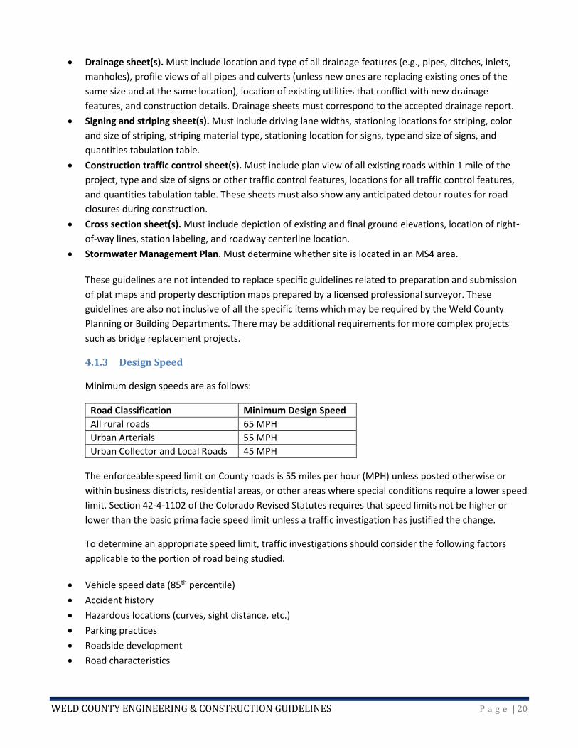
4.1.3 Design Speed
Minimum design speeds are as follows:
Road Classification Minimum Design Speed
All rural roads 65 MPH
Urban Arterials 55 MPH
Urban Collector and Local Roads 45 MPH
The enforceable speed limit on County roads is 55 miles per hour (MPH) unless posted otherwise or
within business districts, residential areas, or other areas where special conditions require a lower speed
limit. Section 42-4-1102 of the Colorado Revised Statutes requires that speed limits not be higher or
lower than the basic prima facie speed limit unless a traffic investigation has justified the change.
To determine an appropriate speed limit, traffic investigations should consider the following factors
applicable to the portion of road being studied.
• Vehicle speed data (85th percentile)
• Accident history
• Hazardous locations (curves, sight distance, etc.)
• Parking practices
• Roadside development
• Road characteristics

WELD COUNTY ENGINEERING & CONSTRUCTION GUIDELINES P a g e | 21
Weld County prefers for designers to use a design speed which is 10 MPH above the desired posted
speed limit. Any change to the existing posted speed limit on a County road requires review by the
Public Works Department and approval by the BOCC.
4.2 HORIZONTAL ALIGNMENT
4.2.1 Horizontal Curves
Horizontal alignment of the roadway is critical for safe and economical operation of motor vehicles
traveling the roadway at the design speed. Horizontal curve design should be based on an appropriate
relationship between design speed, right-of-way, profile grades, and construction costs—and on their
joint relationships with superelevation and side friction. Curves are not required when the delta angle
(total central angle of the circular curve) is less than 1 degree. Curves should be at least 500 feet long for
a central angle of 5 degrees, and the minimum length should be increased 100 feet for each 1 degree
decrease in the central angle. The following figure illustrates a very simple horizontal curve.
Figure 4-1 Horizontal Curve
The formula can be found in the AASHTO A Policy on Geometric Design of Highways and Streets and the
CDOT M & S Standard Plans.
Designers should use every effort to exceed the minimum curve radius when practical. Simple curves in
combination with spiral curves should be used for all roadways. Broken back, compound, or reverse
curves are not recommended.
4.2.2 Superelevation
Proper design of horizontal curves often requires the use of superelevation (roadway banking). Factors
controlling the use of superelevation include climate conditions, terrain conditions, classification of the
road, and the frequency of slow-moving vehicles on the roadway. In general, a lower rate of
superelevation is used in urban areas than in rural areas. Use AASHTO table for minimum radii for design
superelevation rates with emax = 6%.
WELD COUNTY ENGINEERING & CONSTRUCTION GUIDELINES P a g e | 22
4.2.3 Transitions
The superelevation transition section consists of the superelevation runoff and tangent runout sections.
The superelevation runoff is the length of roadway needed to accomplish a change in outside lane cross
slope from zero to full superelevation, or vice versa. The tangent runout section is the length of roadway
needed to accomplish a change in outside lane cross slope from normal cross slope rate to zero, or vice
versa. Additional information pertaining to the lengths and use of transitions for simple and spiral curves
can be found in AASHTO A Policy on Geometric Design of Highways and Streets and the CDOT M & S
Standard Plans.
4.2.4 Cross Slope
Cross slope is necessary to ensure adequate roadway drainage. The typical cross sections (described in
Chapter 2) all show a cross slope of 2%, and this is the County’s preferred value for a paved roadway.
Non-paved roadways should have a cross slope closer to 3 to 4% to help accommodate surface drainage.
Undivided roads should have a normal crown that is a two-way cross slope, with the high point of the
cross section located on the road centerline. Divided roads should have a cross slope on each side of the
divide, with the high point of each section located where the pavement meets the median.
Unusual conditions and transition areas may cause the 2% cross slope requirement to vary. Cross slopes
varying from a minimum of 1% to a maximum of 4% may be allowed depending upon surface type.
Intersections of roads with curbs and gutters sometimes require the use of cross-pans for drainage. At
these areas, the normal two-way 2% cross slope shall transition to a one-way slope adjacent to the cross
pan, with a slope range of 1% to 3%.
4.3 VERTICAL ALIGNMENT
Weld County’s topography is generally flat with gentle slopes, but some areas have steep drainage
basins and rolling hills. When designing roadway vertical alignment, designers should take into account
stopping sight distance requirements for the given speed limit and the challenges of large cut-and-fill
sections.
Vertical curves are classified as either sag or crest curves. Typically, sag curves are controlled by
nighttime driving conditions with headlight visibility restrictions, and crest curves are controlled by
stopping sight distances. Vertical curves should be simple in application and should result in a design
that is safe and comfortable in operation, aesthetically pleasing, and adequate for drainage—especially
when a curb and gutter are used.
4.3.1 Maximum and Minimum Grades
Grade lines are typically controlled by topography and structure clearances, but very flat grade can be
controlled by drainage considerations. Other factors that should be considered are road classifications,
design speed, safety, and construction costs.
A minimum value of 0.5% should be used for road sections with curbs and gutters. In certain conditions,
0.3% may be used. The designer should consider the ultimate design of the roadway, recognizing if a
WELD COUNTY ENGINEERING & CONSTRUCTION GUIDELINES P a g e | 23
curb and gutter may be required in the future, and design for those conditions during the interim
design.
Grades 4% or steeper may require special consideration for drainage or erosion protection.
When using combinations of horizontal and vertical curves, it is important to recognize the driver’s
perspective. Sharp horizontal curvature should not be introduced at or near the top of a pronounced
crest vertical curve. If unavoidable, the horizontal curve should be made longer than the vertical curve
to help minimize the driver’s inability to perceive the horizontal change, especially at night. (For further
details, see AASHTO A Policy on Geometric Design of Highways and Streets and the CDOT Roadway
Design Guide.)
The length of vertical curves can be determined by dividing the rate of vertical curvature by the grade
change or algebraic difference in intersecting grades (%).
L (Length)(ft) = K (rate of curvature) / A (grade change)(%)
A vertical curve is not required when a grade change or the algebraic difference is equal to or less than
0.2%. The Weld County preferred minimum length of a vertical curve is 300’. The allowed minimum is 3
times the roadway design speed.
4.4 SIGHT DISTANCE
Adequate sight distance is one of the most critical factors when designing roadways and intersections.
Limited or obstructed sight distance can lead to accidents. There are several sight distances to consider
when designing a roadway.
4.4.1 Stopping Sight Distance
Stopping sight distance is the length of roadway it takes for a driver to bring a vehicle to a complete
stop. Stopping sight distance is measured from the driver’s point of view, which is considered to be 3.5
feet above the road surface, to an object’s height of 2 feet. Stopping sight distance includes the reaction
time of the driver and braking distance of the vehicle as well as roadway grades (see Table 4-5).
Additional information regarding reaction time and braking distance can be found in AASHTO A Policy on
Geometric Design of Highways and Streets and in Chapter 6.
As shown in Table 4-5, stopping sight distance varies depending upon the percent in grade up or down
within the vertical curve. The designer should account for the varying grades within his or her profile
design and select the appropriate values of stopping sight distance.
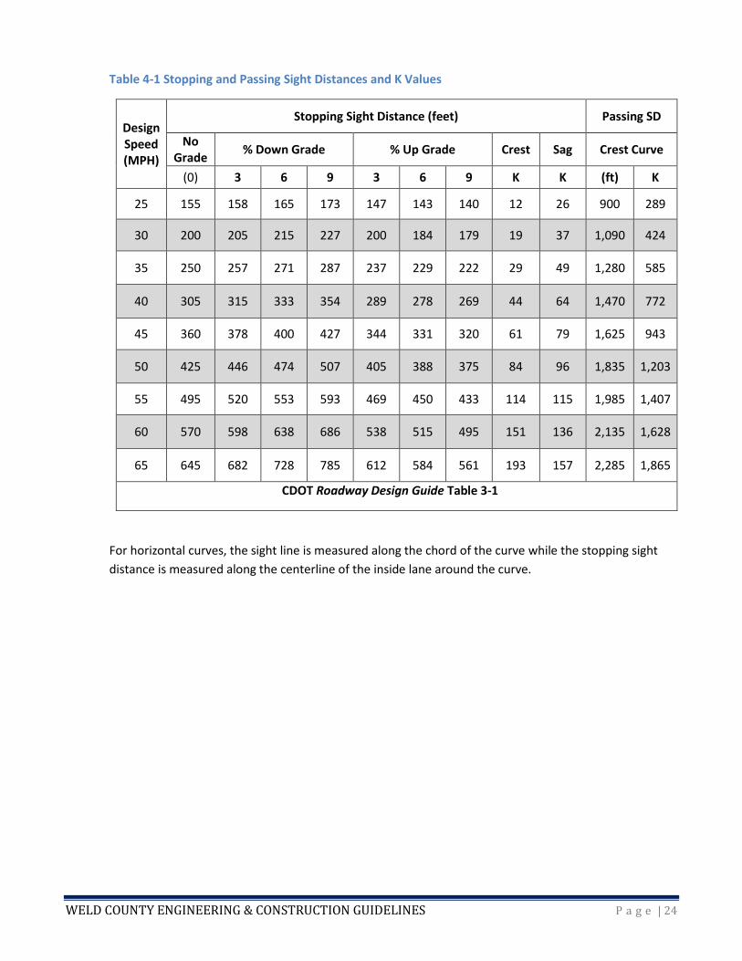
Table 4-1 lists stopping and passing sight distances for various percent grades up or down.
WELD COUNTY ENGINEERING & CONSTRUCTION GUIDELINES P a g e | 24
Table 4-1 Stopping and Passing Sight Distances and K Values
Design Speed (MPH)
Stopping Sight Distance (feet) Passing SD
No Grade
% Down Grade % Up Grade Crest Sag Crest Curve
(0) 3 6 9 3 6 9 K K (ft) K
25 155 158 165 173 147 143 140 12 26 900 289
30 200 205 215 227 200 184 179 19 37 1,090 424
35 250 257 271 287 237 229 222 29 49 1,280 585
40 305 315 333 354 289 278 269 44 64 1,470 772
45 360 378 400 427 344 331 320 61 79 1,625 943
50 425 446 474 507 405 388 375 84 96 1,835 1,203
55 495 520 553 593 469 450 433 114 115 1,985 1,407
60 570 598 638 686 538 515 495 151 136 2,135 1,628
65 645 682 728 785 612 584 561 193 157 2,285 1,865
CDOT Roadway Design Guide Table 3-1
For horizontal curves, the sight line is measured along the chord of the curve while the stopping sight
distance is measured along the centerline of the inside lane around the curve.

WELD COUNTY ENGINEERING & CONSTRUCTION GUIDELINES P a g e | 25
Figure 4-2 Horizontal Sight Distance
Horizontal sight distance may be restricted by obstacles alongside the roadway or even by cut slopes
through a hillside. Other normal roadside objects such as guard railing, concrete barriers, and privacy
fences should be studied for interference with sight distance.
Vertical sight distance is determined by the geometrics of the curve. Figure 4-3 is an example of the
crest vertical curve.
Figure 4-3 Crest Vertical Curve
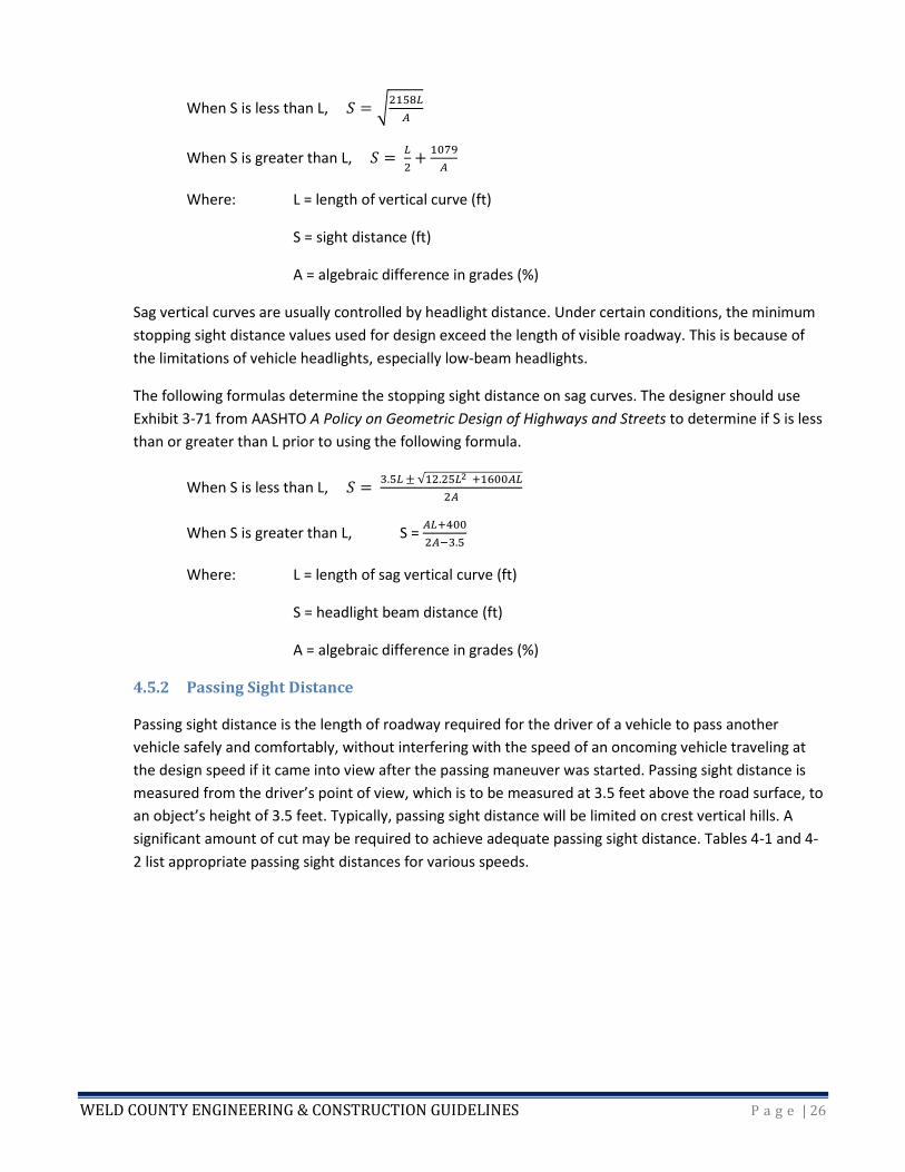
The following formulas determine the stopping sight distance on crest curves:
WELD COUNTY ENGINEERING & CONSTRUCTION GUIDELINES P a g e | 26
When S is less than L, 𝑆 = √2158𝐿
𝐴
When S is greater than L, 𝑆 = 𝐿
2+
1079
𝐴
Where: L = length of vertical curve (ft)
S = sight distance (ft)
A = algebraic difference in grades (%)
Sag vertical curves are usually controlled by headlight distance. Under certain conditions, the minimum
stopping sight distance values used for design exceed the length of visible roadway. This is because of
the limitations of vehicle headlights, especially low-beam headlights.
The following formulas determine the stopping sight distance on sag curves. The designer should use
Exhibit 3-71 from AASHTO A Policy on Geometric Design of Highways and Streets to determine if S is less
than or greater than L prior to using the following formula.
When S is less than L, 𝑆 = 3.5𝐿 ± √12.25𝐿2 +1600𝐴𝐿
2𝐴
When S is greater than L, S = 𝐴𝐿+400
2𝐴−3.5
Where: L = length of sag vertical curve (ft)
S = headlight beam distance (ft)
A = algebraic difference in grades (%)
4.5.2 Passing Sight Distance
Passing sight distance is the length of roadway required for the driver of a vehicle to pass another
vehicle safely and comfortably, without interfering with the speed of an oncoming vehicle traveling at
the design speed if it came into view after the passing maneuver was started. Passing sight distance is
measured from the driver’s point of view, which is to be measured at 3.5 feet above the road surface, to
an object’s height of 3.5 feet. Typically, passing sight distance will be limited on crest vertical hills. A
significant amount of cut may be required to achieve adequate passing sight distance. Tables 4-1 and 4-
2 list appropriate passing sight distances for various speeds.
WELD COUNTY ENGINEERING & CONSTRUCTION GUIDELINES P a g e | 27
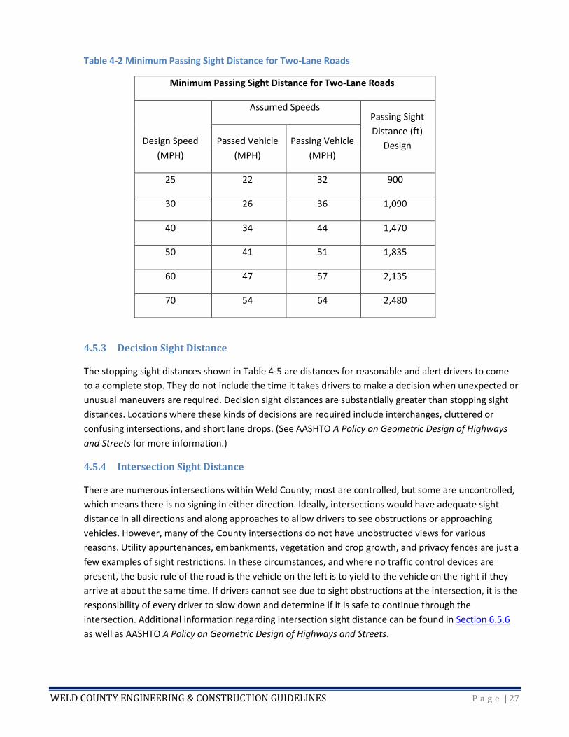
Table 4-2 Minimum Passing Sight Distance for Two-Lane Roads
Minimum Passing Sight Distance for Two-Lane Roads
Design Speed
(MPH)
Assumed Speeds Passing Sight
Distance (ft)
Design Passed Vehicle
(MPH)
Passing Vehicle
(MPH)
25 22 32 900
30 26 36 1,090
40 34 44 1,470
50 41 51 1,835
60 47 57 2,135
70 54 64 2,480
4.5.3 Decision Sight Distance
The stopping sight distances shown in Table 4-5 are distances for reasonable and alert drivers to come
to a complete stop. They do not include the time it takes drivers to make a decision when unexpected or
unusual maneuvers are required. Decision sight distances are substantially greater than stopping sight
distances. Locations where these kinds of decisions are required include interchanges, cluttered or
confusing intersections, and short lane drops. (See AASHTO A Policy on Geometric Design of Highways
and Streets for more information.)
4.5.4 Intersection Sight Distance
There are numerous intersections within Weld County; most are controlled, but some are uncontrolled,
which means there is no signing in either direction. Ideally, intersections would have adequate sight
distance in all directions and along approaches to allow drivers to see obstructions or approaching
vehicles. However, many of the County intersections do not have unobstructed views for various
reasons. Utility appurtenances, embankments, vegetation and crop growth, and privacy fences are just a
few examples of sight restrictions. In these circumstances, and where no traffic control devices are
present, the basic rule of the road is the vehicle on the left is to yield to the vehicle on the right if they
arrive at about the same time. If drivers cannot see due to sight obstructions at the intersection, it is the
responsibility of every driver to slow down and determine if it is safe to continue through the
intersection. Additional information regarding intersection sight distance can be found in Section 6.5.6
as well as AASHTO A Policy on Geometric Design of Highways and Streets.
WELD COUNTY ENGINEERING & CONSTRUCTION GUIDELINES P a g e | 28
4.5 INTERSECTIONS
By definition, an intersection is the location where two or more roadways meet or join together. This
occurs at at-grade crossings, interchanges, or grade separations without ramps. All of the County-owned
intersections in Weld County are at-grade intersections.
Generally, there is more potential for conflict at intersections than on straight sections of roadway, so
intersections usually have higher accident rates. Chapter 9 of AASHTO A Policy on Geometric Design of
Highways and Streets discusses intersections and provides guidance on design details. Designers should
also refer to the CDOT Roadway Design Guide. The sections below highlight a few key aspects of
intersection design. See also Chapter 2 for cross section drawings.
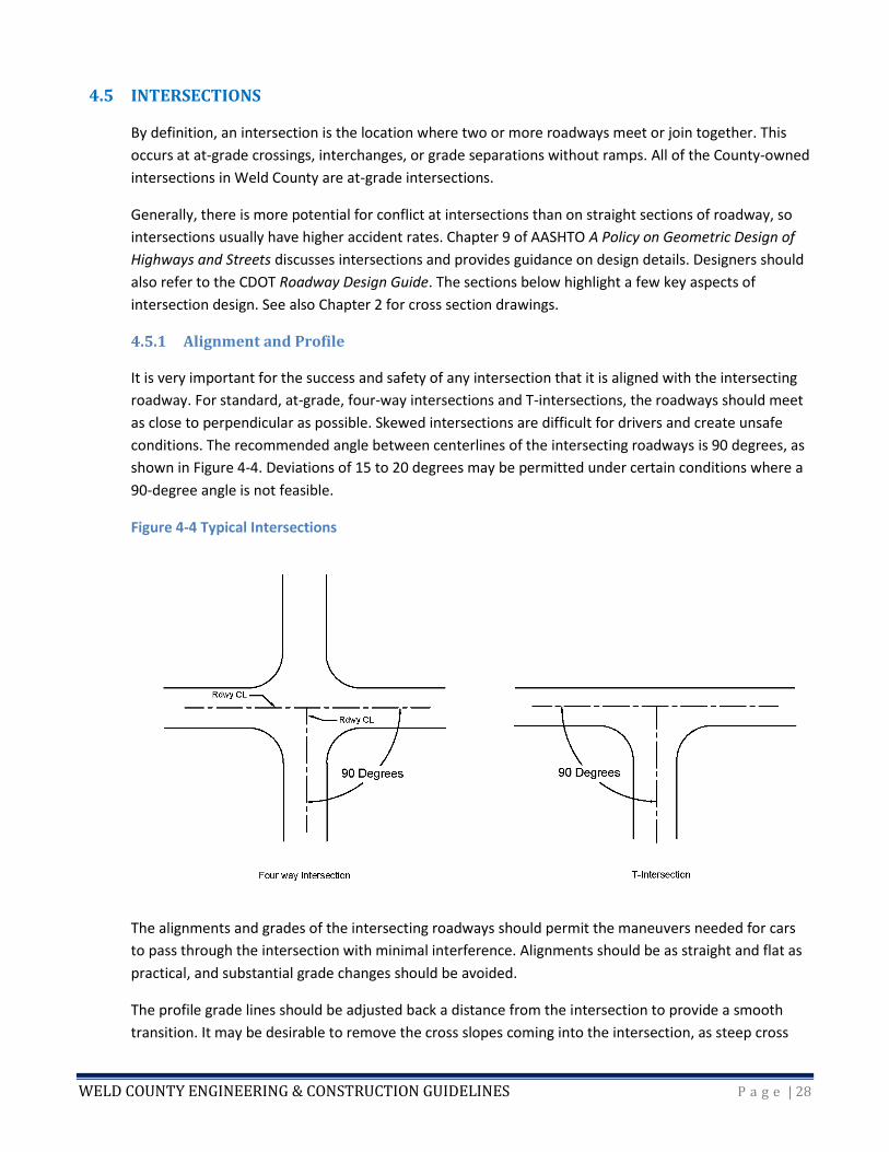
4.5.1 Alignment and Profile
It is very important for the success and safety of any intersection that it is aligned with the intersecting
roadway. For standard, at-grade, four-way intersections and T-intersections, the roadways should meet
as close to perpendicular as possible. Skewed intersections are difficult for drivers and create unsafe
conditions. The recommended angle between centerlines of the intersecting roadways is 90 degrees, as
shown in Figure 4-4. Deviations of 15 to 20 degrees may be permitted under certain conditions where a
90-degree angle is not feasible.
Figure 4-4 Typical Intersections
The alignments and grades of the intersecting roadways should permit the maneuvers needed for cars
to pass through the intersection with minimal interference. Alignments should be as straight and flat as
practical, and substantial grade changes should be avoided.
The profile grade lines should be adjusted back a distance from the intersection to provide a smooth
transition. It may be desirable to remove the cross slopes coming into the intersection, as steep cross
WELD COUNTY ENGINEERING & CONSTRUCTION GUIDELINES P a g e | 29
slopes or grade changes create an undesirable bump at the intersection and may require reconstruction
to correct. A smooth transition is particularly important at intersections where drivers do not reduce
their speed or come to a stop. Designers should remember that intersections which are currently stop-
controlled may not be in the future.
4.5.2 Corner Radii
Corner radii are another critical aspect of intersection design. Corner radii are selected based on the
turning radii of different design vehicles. Chapter 2 of AASHTO’s A Policy on Geometric Design of
Highways and Streets discusses design vehicles and their different turning radii. The four classes of
design vehicles are: passenger cars, buses, trucks, and recreational vehicles.
The designer should select the appropriate design vehicle for the intersection(s), taking into account not
only expected traffic in the near future but also, to the extent possible, traffic changes that might occur
long-term. Consideration should be given to the largest design vehicle likely to use the intersection with
considerable frequency.
Chapter 9 of A Policy on Geometric Design of Highways and Streets summarizes the minimum edge of
traveled way design for the four classes of design vehicles. Usually, the simplest curves to construct are
the simple curve with taper and the three-centered compound (symmetric) radii. Other compound
curves can be difficult to implement in the field. For intersections on arterial and collector roadways,
designers should consider a minimum radius of 65 feet, following a simple curve with taper radii. This
allows larger trucks to make right turns without their rear tires going off the road and without veering
into opposing vehicle paths.
4.5.3 Auxiliary Lanes
See Chapter 6 for information on auxiliary lanes.
4.6 CUL-DE-SACS
Cul-de-sacs and dead-end roadways are not common in the County, but are sometimes found in
subdivision and residential areas. Cul-de-sacs should be designed with a radius large enough to allow the
majority of vehicle types expected to use the cul-de-sac to make a u-turn without having to back up. The
most common design is a circular cul-de-sac with or without a center island. Chapter 5 of A Policy on
Geometric Design of Highways and Streets offers additional design criteria and other types of cul-de-
sacs. The designer should consult the relevant fire protection authority for their minimum criteria.
4.7 BRIDGES
This section is not intended to cover bridge design in great detail. It covers only general guidelines. More
detailed bridge design information can be found in the latest editions of the AASHTO LRFD bridge design
specifications and the CDOT Drainage Design Manual and Bridge Design Manual.
WELD COUNTY ENGINEERING & CONSTRUCTION GUIDELINES P a g e | 30
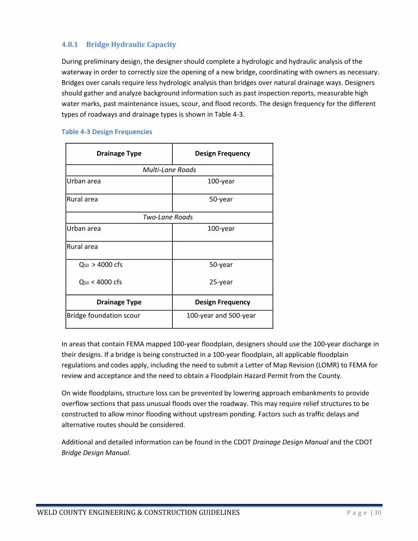
4.8.1 Bridge Hydraulic Capacity
During preliminary design, the designer should complete a hydrologic and hydraulic analysis of the
waterway in order to correctly size the opening of a new bridge, coordinating with owners as necessary.
Bridges over canals require less hydrologic analysis than bridges over natural drainage ways. Designers
should gather and analyze background information such as past inspection reports, measurable high
water marks, past maintenance issues, scour, and flood records. The design frequency for the different
types of roadways and drainage types is shown in Table 4-3.
Table 4-3 Design Frequencies
Drainage Type Design Frequency
Multi-Lane Roads
Urban area 100-year
Rural area 50-year
Two-Lane Roads
Urban area 100-year
Rural area
Q50 > 4000 cfs
Q50 < 4000 cfs
50-year
25-year
Drainage Type Design Frequency
Bridge foundation scour 100-year and 500-year
In areas that contain FEMA mapped 100-year floodplain, designers should use the 100-year discharge in
their designs. If a bridge is being constructed in a 100-year floodplain, all applicable floodplain
regulations and codes apply, including the need to submit a Letter of Map Revision (LOMR) to FEMA for
review and acceptance and the need to obtain a Floodplain Hazard Permit from the County.
On wide floodplains, structure loss can be prevented by lowering approach embankments to provide
overflow sections that pass unusual floods over the roadway. This may require relief structures to be
constructed to allow minor flooding without upstream ponding. Factors such as traffic delays and
alternative routes should be considered.
Additional and detailed information can be found in the CDOT Drainage Design Manual and the CDOT
Bridge Design Manual.
WELD COUNTY ENGINEERING & CONSTRUCTION GUIDELINES P a g e | 31
4.8.2 Freeboard
A minimum clearance, or freeboard, shall be provided between the water surface elevation and the low
girder of the bridge. The freeboard is required to allow for wave action, ice, debris, and uncertainty
during estimation.
The minimum freeboard for a bridge should follow these guidelines:
• For a high-debris stream, freeboard should be 4 feet or more.
• For low- to moderate-debris streams, the freeboard should be determined using the following equation.
|Freeboard = 0.1 Q 0.3 + 0.008 V2 |
where Q is design discharge in (cfs) and V is the mean velocity of the design flow through the
bridge in foot per second (ft/s), (16 ft/s max). If the mean velocity is greater than 16 ft/s, the
bridge should be widened. The minimum freeboard allowed will be 1 foot.
4.8.3 Bridge Railing
Bridge railing should be provided along bridge edges to protect both drivers and pedestrians. Bridge
railing differs from guard railing, as bridge railing is not intended to flex upon impact or absorb impacts.
Concrete curbs are used in conjunction with bridge railing to offer the rigidity required to handle impact
loads.
Weld County does not have a standard bridge railing, and the designer should select a railing that best
fits the use of the bridge under design while meeting current industry standards. If the bridge is in an
urban or urbanizing area, the need for pedestrian railing should also be considered. The CDOT M & S
Standard Plans identify several different railing options and configurations that the designer may
consider. The AASHTO bridge design documents provide additional information as well.
4.8.4 Minimum Structural Requirements
Design loadings for bridges shall comply with the latest editions of the AASHTO LRFD Bridge Design
Specifications and CDOT bridge design publications.
4.8 ALTERNATIVE DESIGN APPROVAL
The intent of these guidelines is to provide a starting point with widely accepted design options.
However, new technologies, materials, and construction approaches may also provide adequate
protection of the public health, safety, and welfare. The County will consider requests for alternative
designs on a case-by-case basis.
County Code Sec. 8-6-40 requires passage of a resolution by the BOCC for acceptance of maintenance
responsibility by the County. For infrastructure that will be requested to be maintained by the County,
requests for alternate designs shall be identified in a written attachment to the initial submittal of
construction plans. The request shall consist of the following.

WELD COUNTY ENGINEERING & CONSTRUCTION GUIDELINES P a g e | 32
1. Identification of the provision to be waived or varied;
2. Identification of the alternative design or construction criteria to adhere to; and
3. A thorough justification for the alternative, including impact on public safety, capital costs,
materials, and maintenance costs.
The request shall be prepared, stamped, signed, and dated by a professional civil engineer licensed to
practice in Colorado. Requests will be reviewed by the Public Works Director or his/her designee to
ensure they will:
1. Achieve the intended result,
2. Meet the design intent of the WCECG,
3. Comply with Weld County Code,
4. Achieve a result that is comparable or superior in design and quality to the guidelines in the WCECG,
5. Not adversely affect safety or maintenance operations,
6. Not adversely affect maintenance or maintenance costs, and
7. Not adversely affect aesthetic appearance.
For infrastructure that will not be maintained by the County, requests for alternative designs shall be
identified in a written attachment to the construction plans. Requests will be reviewed by the Public
Works Director or his/her designee to ensure they will adequately protect public health, safety, and
welfare.
The Public Works Director reserves the right to deny, or allow his or her designee to deny, any request
for alternative designs if doing so is in the interest of public health, safety, and welfare.
WELD COUNTY ENGINEERING & CONSTRUCTION GUIDELINES P a g e | 33
CHAPTER 5 – DRAINAGE CRITERIA
5.1 DRAINAGE POLICY
The County’s Storm Drainage Criteria are codified in Article XII of Chapter 23 of the Weld County Code. It
adopts the most recent edition of the Urban Drainage and Flood Control District’s Urban Storm Drainage
Criteria Manual (Volumes 1-3), with amendments.
5.1.1 Recommendations for Adhering to Weld County Drainage Policy
The recommendations to adhere to Weld County storm drainage policy are summarized below.
• The storm drainage system is a subsystem of the total natural water resource system.
• Planning and design of stormwater drainage systems should not be based on the premise that problems
can be transferred from one location to another.
• Storm drainage strategy should be a flexible, multi-objective, and multi-means effort.
• In Weld County, storm drainage design for new development should accommodate agricultural facilities
and practices.
• Design of the constructed stormwater drainage system should consider the features and functions of
the existing natural drainage system.
• Storm drainage design for new development should give full consideration to downstream impacts and
safe conveyance of upstream off-site flows entering the system. Prevention of harm is paramount.
• The stormwater management systems should receive regular maintenance.
• Storm drainage design for new development should give full consideration to erosion prevention.
• Adequate floodplain capacity needs to be preserved consistent with FEMA and Colorado Water
Conservation Board (CWCB) regulations.
• Land development should reserve sufficient floodplain width to accommodate lateral stream channel
movement.
• Retention facilities are not allowed in Weld County without the issuance of a variance. See Section 5.11
below.
5.1.2 Data Collection
The County makes full use of information and data provided by FEMA, the National Oceanographic and
Atmospheric Administration (NOAA), the U.S. Geological Survey (USGS), private consulting engineers,
and the CWCB. Before commencing design of any drainage project, designers should collect and
evaluate data for the particular watershed area under consideration. Then, the basis and goals for the
design should be agreed upon with the affected jurisdictions and other stakeholders.
5.2 DRAINAGE LAW
Refer to the drainage law chapter of the UDFCD Manual (Volume 1) for more information on drainage
law as it relates to stormwater runoff and floodplain management.
WELD COUNTY ENGINEERING & CONSTRUCTION GUIDELINES P a g e | 34
5.2.1 General Principles of Colorado Drainage Law Applicable to Weld County
• The owner of upstream property possesses a natural easement on land downstream for drainage of
surface water flowing in its natural course. The upstream property owner may alter drainage conditions
so long as the water is not sent downstream in a manner or quantity to do more harm to the
downstream land than formerly. Bittersweet Farms, Inc. v. Zimbelman, 976 P.2d 326 (Colo. App. 1998).
• A natural watercourse may be used as a conduit or outlet for the drainage of lands, so long as the
augmented flow will not tax the stream beyond its capacity and cause flooding of adjacent lands.
Ambrosio v. Pearl-Mack Construction Co., 351 P.2d 803 (Colo. 1960).
• Ditch corporations that own ditches owe a duty to those property owners through which their ditches
pass to maintain their ditches using ordinary care so as to prevent damage to adjoining real property.
Oliver v. Amity Mut. Irrigation Co., 994 P.2d 495 (Colo. App. 1999).
• A “dangerous condition” constitutes an unreasonable risk to the health or safety of the public, which is
known to exist or which in the exercise of reasonable care should have been known to exist and which
condition is proximately caused by the negligent act or omission of the public entity in constructing or
maintaining such facility. 24-10-103 C.R.S.
• A professional engineer is required not only to serve the interests of his or her employer/client but is
also required—as his or her primary obligation—to protect the safety, health, property, and welfare of
the public in compliance with Rule 3.1.1 of the Bylaws and Rules of The State Board of Licensure for
Architects, Professional Engineers and Professional Land Surveyors.
5.2.2 Floodplain Management Obligations
For more information regarding floodplain management obligations and requirements, refer to Chapter
8, Article X, and Chapter 23, Article XI, of the Weld County Code; the 2011 CWCB Floodplain Regulations;
and Sections 44CFR 59, 60, and 65 of FEMA’s National Flood Insurance Program (NFIP) regulations.
• The boundaries of the floodplain should be accurately determined and based on a reasonable standard.
Mallett v. Mamarooneck, 125 N.E. 2d 875 (N.Y. 1955).
• Adoption of a floodplain regulation to regulate flood-prone areas is a valid exercise of police power and
is not a taking as long as the regulation does not go beyond protection of the public’s health, safety,
morals, and welfare. Hermanson v. Board of County Commissioners of Fremont, 595 P.2d 694 (Colo. App.
1979).
• The adoption by a municipality of floodplain ordinances to regulate flood-prone areas is a valid exercise
of police power and is not a taking. Morrison v. City of Aurora, 745 P.2d 1042 (Colo. App. 1987).
5.3 SUBMITTAL CRITERIA
Refer to the Planning & Zoning Department’s Engineering page of the County website for submittal
information.
5.3.1 Master Plan Drainage Criteria
Refer to the planning chapter of the UDFCD Manual (Volume 1) for information regarding the criteria
that should be considered when preparing a master drainage plan.
WELD COUNTY ENGINEERING & CONSTRUCTION GUIDELINES P a g e | 35
Weld County has the following adopted master drainage plans:
• Tri-Town Study
• Master Drainage Plan for the Area Surrounding Weld County Parkway
5.3.2 Land Use Application Drainage Criteria
For subdivisions, USRs, Site Plans, etc., refer to Chapter 23, Article XII, Chapter 24, Article VII, Section 24-
7-110 and 24-7-120, of the Weld County Code, and the Planning & Zoning webpage.
5.3.3 Roadway Drainage Criteria
• Borrow ditches need to be sized to reduce the potential for roadway overtopping. Overtopping of the
roadway cannot result in more than 6 inches of water on the road during the 10-year event.
• Culverts need to be sized to reduce the potential for backwater effects on adjacent houses or
businesses. Culverts passing under Weld County roads must be designed for the 10-year storm and have
a minimum diameter of 15 inches. Additionally, the culvert must be sized so that road overtopping does
not result in more than 6 inches of water on the road in the 10-year event and 18 inches of water on the
road in the 100-year event.
• If the roadway is being constructed in a floodplain, all applicable floodplain regulations and codes apply,
including the need to submit an LOMR to FEMA for review and acceptance if applicable.
5.4 RAINFALL
The designer should use the most appropriate and best available data for the project area in
determining the rainfall quantities. This section presents the methods used to develop rainfall
information for hydrological analyses. For more information regarding the development of rainfall
information, refer to the rainfall chapter of the UDFCD Manual (Volume 1).
5.4.1 Design Storms
The rainfall depth-duration frequency maps presented in the UDFCD Manual can only be used for those
areas of Weld County shown on Figures 5-1 through 5-12 in the UDFCD Manual. Drainage designs for
locations outside these areas should use the depth-duration frequency information provided in the
Precipitation-Frequency Atlas of the Western United States (Volume 2 – Colorado), published by NOAA.
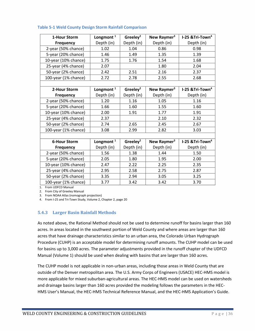
The NOAA atlas can be accessed on the NOAA website. Table 5-1 can be used if the proposed project is
near one of the towns shown.
5.4.2 The Rational Method
The Rational Method is one method for determining runoff from a proposed development or road
construction project. Note that it should not be used for basins greater than 160 acres. The UDFCD
spreadsheets can also be used for basins that are no greater than 160 acres. Refer to the rainfall chapter
of the UDFCD Manual (Volume 1) for more information regarding the rainfall parameters required to use
the Rational Method.
WELD COUNTY ENGINEERING & CONSTRUCTION GUIDELINES P a g e | 36
Table 5-1 Weld County Design Storm Rainfall Comparison
1-Hour Storm Frequency
Longmont 1 Depth (in)
Greeley2 Depth (in)
New Raymer3 Depth (in)
I-25 &Tri-Town4
Depth (in)
2-year (50% chance) 1.02 1.04 0.86 0.98
5-year (20% chance) 1.46 1.49 1.35 1.39
10-year (10% chance) 1.75 1.76 1.54 1.68
25-year (4% chance) 2.07 1.80 2.04
50-year (2% chance) 2.42 2.51 2.16 2.37
100-year (1% chance) 2.72 2.78 2.55 2.68
2-Hour Storm Frequency
Longmont 1 Depth (in)
Greeley2 Depth (in)
New Raymer3 Depth (in)
I-25 &Tri-Town4
Depth (in)
2-year (50% chance) 1.20 1.16 1.05 1.16
5-year (20% chance) 1.66 1.60 1.55 1.60
10-year (10% chance) 2.00 1.91 1.77 1.91
25-year (4% chance) 2.37 2.10 2.32
50-year (2% chance) 2.74 2.65 2.45 2.67
100-year (1% chance) 3.08 2.99 2.82 3.03
6-Hour Storm Frequency
Longmont 1 Depth (in)
Greeley2 Depth (in)
New Raymer3 Depth (in)
I-25 &Tri-Town4
Depth (in)
2-year (50% chance) 1.56 1.38 1.44 1.50
5-year (20% chance) 2.05 1.80 1.95 2.00
10-year (10% chance) 2.47 2.22 2.25 2.35
25-year (4% chance) 2.95 2.58 2.75 2.87
50-year (2% chance) 3.35 2.94 3.05 3.25
100-year (1% chance) 3.77 3.42 3.42 3.70 1. From UDFCD Manual 2. From City of Greeley Manual 3. From NOAA Atlas (nomograph projection) 4. From I-25 and Tri-Town Study, Volume 2, Chapter 2, page 20
5.4.3 Larger Basin Rainfall Methods
As noted above, the Rational Method should not be used to determine runoff for basins larger than 160
acres. In areas located in the southwest portion of Weld County and where areas are larger than 160
acres that have drainage characteristics similar to an urban area, the Colorado Urban Hydrograph
Procedure (CUHP) is an acceptable model for determining runoff amounts. The CUHP model can be used
for basins up to 3,000 acres. The parameter adjustments provided in the runoff chapter of the UDFCD
Manual (Volume 1) should be used when dealing with basins that are larger than 160 acres.
The CUHP model is not applicable in non-urban areas, including those areas in Weld County that are
outside of the Denver metropolitan area. The U.S. Army Corps of Engineers (USACE) HEC-HMS model is
more applicable for mixed suburban-agricultural areas. The HEC-HMS model can be used on watersheds
and drainage basins larger than 160 acres provided the modeling follows the parameters in the HEC-
HMS User’s Manual, the HEC-HMS Technical Reference Manual, and the HEC-HMS Application’s Guide.
WELD COUNTY ENGINEERING & CONSTRUCTION GUIDELINES P a g e | 37
The HEC-HMS model is also recommended for determining the peak flow of large off-site stream flows
moving through a proposed development site.
The drainage report should fully describe the rationale for the chosen rainfall method of determining
runoff including the choices for all the various model parameters. The report must contain copies of all
applicable tables and reference materials in an appendix, as well as electronic copies of any
spreadsheets prepared must fully document the assumptions for reviewing purposes.
Where development is proposed in larger watersheds, design hydrology should use longer storm
durations appropriate for the size and time of concentration of the entire watershed. In all cases, the
actual calculated time of concentration should be used. Refer to the rainfall chapter of the UDFCD
Manual (Volume 1).
5.5 RUNOFF
For more information regarding the development of runoff information, refer to Chapter 23, Article XII,
of the Weld County Code and the runoff chapter of the UDFCD Manual (Volume 1).
5.5.1 Differences between Weld County and the UDFCD Manual
Weld County does not allow the use of the Urban Check Method when determining the five-year historic
runoff amount.
Weld County does not allow detention release rates based on soil types.
Weld County will allow the use of other modeling methodologies on a case-by-case basis when
complete documentation of all assumptions is provided. Weld County reserves the right to review
alternative methods and compare with other commonly used approaches, including those discussed in
the UDFCD Manual.
5.6 STREET DRAINAGE
For information regarding the design of stormwater collection and conveyance systems, refer to Chapter
8, Article VI, Section 8-6-15, Road acceptance policy, and Chapter 23, Article XII, of the Weld County
Code, and the streets/inlets/storm sewers chapter of the UDFCD Manual (Volume 1).
5.6.1 Inlets
The design guidelines provided in the streets/inlets/storm sewers chapter of the UDFCD Manual
(Volume 1) should be used when designing stormwater inlets.
5.6.2 Pipes
The design guidelines provided in the streets/inlets/storm sewers chapter of the UDFCD Manual
(Volume 1) should be used when designing stormwater pipes.
The minimum allowable size for a sewer or culvert within a public right-of-way or public drainage
easement shall be 15 inches in diameter or equivalent open area. The Department of Public Works

WELD COUNTY ENGINEERING & CONSTRUCTION GUIDELINES P a g e | 38
should be contacted to determine which types of storm sewer pipes are permissible for use in public
rights-of-way or public drainage easements. Pipes constructed under the travel lanes of a new public
roadway shall be RCP or approved equal. All RCPs shall have adequate minimum cover to protect them
from damage during construction. Pipes constructed in right-of-way for private driveway access in rural
areas shall be CMP or approved equal. All CMP pipes shall be constructed with a minimum cover of 12
inches. The contractor must provide shop drawings for any precast concrete box culvert (CBC), which
shall be approved for use by the engineer.
The Manning’s roughness coefficient “n” for all storm sewer capacity calculations in Weld County shall
be 0.013 regardless of pipe material (e.g., concrete, PVC, or HDPE)—with the exception of corrugated
metal pipes, which shall have a coefficient of 0.025.
5.7 MAJOR DRAINAGE
For more information regarding the design of major drainage systems, refer to Chapter 23, Article XII, of
the Weld County Code and the major drainage chapter of the UDFCD Manual (Volume 1).
5.7.1 Design Flows
The major drainage system must be able to convey the fully developed flow from a watershed for the 1-
hour, 100-year event without significant damage to the system.
Open Channel Design Principles:
• Grass-lined open channels conveying less than 50 cfs may reduce the minimum 1.0-foot freeboard
requirement to the freeboard required to convey 1.33 times the 100-year design flow. The reduced
freeboard may only occur if a 1.0-foot minimum freeboard is not physically possible and a variance
request is submitted.
• Maximum side slopes may be as steep as 3H:1V. However, the design engineer should address how the
channels will be maintained since it may not be safe to mow on slopes that are greater than 4H:1V.
5.7.5 Erosion Protection Design Criteria
Protecting major drainage channels from erosion is critical for maintaining channel stability. Channels
need to be designed so that they remain stable until they are fully constructed or vegetated. It may be
necessary to install riprap, straw bales, erosion control logs, or erosion control blankets in the channels
to ensure that they remain stable. The best management practices (BMPs) outlined in the UDFCD
Manual (Volume 3) should be used to ensure stability.
5.8 MINOR DRAINAGE
For more information regarding the design of minor drainage systems, refer to Chapter 23, Article XII, of
the Weld County Code and the major drainage chapter of the UDFCD Manual (Volume 1).
5.8.1 Design Flows
Road overtopping not to exceed 6 inches in the 10-year event and 18 inches in the 100-year event.

WELD COUNTY ENGINEERING & CONSTRUCTION GUIDELINES P a g e | 39
It should be noted that storm drainage facilities designed in accordance with the design storm
frequencies will be flooded in storm events exceeding the return period shown.
5.8.2 Design Criteria
The design criteria outlined in Chapter 23 of the Weld County Code should be followed when designing
minor drainage.
5.8.3 Erosion Protection Design Criteria
Protecting minor drainage channels from erosion is critical for maintaining channel stability. Channels
need to be designed so that they remain stable until they are fully constructed or vegetated. It may be
necessary to install riprap, straw bales, erosion control logs, or erosion control blankets in the channels
to ensure that they remain stable. The BMPs outlined in the UDFCD Manual (Volume 3) should be used
to ensure stability.
5.9 HYDRAULIC STRUCTURES
For more information regarding the design of hydraulic structures, refer to Chapter 23, Article XII, of the
Weld County Code and the hydraulic structures chapter of the UDFCD Manual (Volume 2).
5.9.1 Design Flows
Hydraulic structures need to be designed for the 100-year design event and other minor design
discharges as applicable.
5.9.2 Design Criteria
The design criteria for check and drop structures, conduit outlet structures, bridges, transitions and
constrictions, bends and confluences, and rundowns should follow the design criteria outlined in the
hydraulic structures chapter of the UDFCD Manual (Volume 2). Additionally, bridges must be designed
so that the low chord elevation of the bridge is a minimum of 1 foot above the 100-year water course
energy grade line.
Weld County will allow the use of other modeling methodologies on a case-by-case basis when
complete documentation of all assumptions is provided. Weld County reserves the right to review
alternative methods and compare with other commonly used approaches, including those discussed in
the UDFCD Manual.
5.9.3 Use of UDFCD Design Aids
The design engineer is encouraged to use the spreadsheets and programs provided by the UDFCD to
assist in designing hydraulic structures. Other software programs may be used, but the designs will be
verified using the UDFCD programs and spreadsheets. The most current version of the UDFCD
spreadsheets can be downloaded from the UDFCD website.
WELD COUNTY ENGINEERING & CONSTRUCTION GUIDELINES P a g e | 40
5.9.4 Use of HEC-RAS
It is acceptable to use HEC-RAS to determine the hydraulic characteristics of the hydraulic structure.
HEC-RAS is useful in sizing hydraulic structures. Standard modeling practices accepted by FEMA should
be used when performing HEC-RAS modeling.
It is not acceptable to rely on HEC-RAS output for estimating maximum velocities for erosive or hazard
considerations or local scour in a channel. A more detailed hydraulic analysis of the specific cross
section, accounting for variable velocities across the channel, is necessary.
5.9.5 FEMA Floodplain Considerations
Construction of hydraulic structures within FEMA floodplains must not increase the 100-year water
surface elevation. Per FEMA regulations, a Flood Hazard Development Permit will be required for the
construction of channels and other major drainage system components within the FEMA mapped 100-
year floodplain. It may be necessary to submit to FEMA a Conditional Letter of Map Revision (CLOMR)
followed by an LOMR as part of the development process. All design engineering of the hydraulic
structures must follow accepted FEMA methodology. For more information regarding the design of
hydraulic structures, refer to Chapter 23, Article XII, of the Weld County Code.
5.9.6 Erosion Protection Design Criteria
Protecting hydraulic structures from erosion is critical for maintaining channel stability. Hydraulic
structures need to be designed so that the channel remains stable until it is fully constructed or
vegetated. It may be necessary to install riprap, straw bales, erosion control logs, or erosion control
blankets in the channels and around the hydraulic structures to ensure that they remain stable. The
BMPs outlined in the UDFCD Manual (Volume 3) should be used to ensure stability.
5.10 CULVERTS
For more information regarding the design of culverts, refer to Chapter 8, Article III and Appendix 8-B,
and Chapter 23, Article XII, of the Weld County Code and the culverts chapter of the UDFCD Manual
(Volume 2). See also the latest edition of the AASHTO Roadside Design Guide.
5.10.1 Sizing
The minimum culvert capacity is the capacity required to convey the 10-year storm with 6 inches or less
water overtopping the road. However, the minimum culvert diameter allowed in public rights-of-way is
15 inches. Weld County may require additional culvert capacity in order to prevent flooding of adjacent
properties. As noted previously, a road cannot be overtopped by more than 6 inches of water during the
10-year event.
Culverts should be installed to the minimum slope required to prevent sediment deposition within the
pipe. The slope should be checked for each design, and if the proper minimum velocity is not obtained,
other design options should be evaluated.
WELD COUNTY ENGINEERING & CONSTRUCTION GUIDELINES P a g e | 41
The design engineer is encouraged to use the spreadsheets and programs provided by the UDFCD to
assist in designing culverts. Other software programs may be used, but the designs will be verified using
the UDFCD programs and spreadsheets. The most current version of the UDFCD spreadsheets can be
downloaded from the UDFCD website.
Weld County will allow the use of other modeling methodologies on a case-by-case basis when
complete documentation of all assumptions is provided. Weld County reserves the right to review
alternative methods and compare with other commonly used approaches, including those discussed in
the UDFCD Manual.
The Department of Public Works will be contacted to determine which types of storm sewer pipes are
permissible for use in public rights-of-way or public drainage easements.
5.10.2 Materials
Weld County allows the installation and use of commonly available culvert types such as reinforced
concrete pipe (RCP) and corrugated metal pipe (CMP). Weld County will allow the use of other culvert
types on a case-by-case basis when complete documentation of all culvert specifications is provided.
Culverts that are to be installed in a public right-of-way that is routinely burned must be made of either
concrete or metal. Plastic pipes (PVC, ADS, etc.) will not be allowed in public rights-of-way that are
subject to weed burning.
5.10.3 Cover
All culverts must be installed with a minimum of 1 foot of cover. If 1 foot of cover is not possible, the
culvert material must be rated for a minimum of HS-20 loading or the largest expected loads crossing it
(i.e., oil rigs, semis, etc.).
5.10.4 End Sections and Trash Racks
At a minimum, culverts installed in public rights-of-way must be equipped with a flared end section on
the culvert entrance and outlet. Erosion protection such as riprap may be required. If riprap is required,
it must be installed on top of a geotextile and properly designed filter bed. Riprap designs need to use
the design methodologies outlined in the hydraulic structures chapter of the UDFCD Manual (Volume 2).
There may be situations in which other types of culvert inlets are necessary. In those situations, the
design methodologies outlined in the culverts chapter of the UDFCD Manual (Volume 2) should be used.
Weld County will allow the use of other modeling methodologies on a case-by-case basis when
complete documentation of all assumptions is provided. Weld County reserves the right to review
alternative methods and compare with other commonly used approaches, including those discussed in
the UDFCD Manual.
Weld County does not maintain trash racks at culverts so they will only be approved on a case-by-case
basis. Debris or a person carried into the culvert will impinge against the rack, leading to pressurized
conditions within the culvert and virtually destroying its flow capacity—thereby creating a greater
hazard to the public or a person trapped in the culvert than would be created by not having a trash rack.
WELD COUNTY ENGINEERING & CONSTRUCTION GUIDELINES P a g e | 42
Weld County does not recommend the use of collapsible gratings.
5.10.5 Maintenance
Culverts located outside County-maintained road rights-of-way are not maintained by the County. The
owners of those culverts are responsible for their maintenance. Culverts that are part of a subdivision
drainage plan are maintained by the respective homeowner’s association. Those culverts should be
maintained and cleaned out annually or on an as-needed basis to ensure proper drainage of the
subdivision.
5.10.6 Erosion Protection Design Criteria
Erosion protection for culverts needs to be designed so that the channel remains stable until it is fully
constructed or vegetated. It may be necessary to install riprap, straw bales, erosion control logs, or
erosion control blankets in the channels in the vicinity of the culverts to ensure that erosion does not
occur at or near the culvert. The BMPs outlined in the UDFCD Manual (Volume 3) should be used to
ensure stability.
5.11 STORAGE
For more information regarding the design of storage, refer to Chapter 23 of the Weld County Code and
the storage chapter of the UDFCD Manual (Volume 2).
5.11.1 Detention Criteria
Whenever the area limits outlined in the storage chapter of the UDFCD Manual (Volume 2) Table 12-5
are exceeded, Weld County recommends or may require the use of hydrograph flood routing
procedures.
Detention ponds should not be located in the FEMA mapped 100-year floodplain.
Whenever a master plan approved by Weld County recommends detention sites and release rates or on-
site detention storage and release rates, the sizing and rates recommended in the master plan must be
used in the final design of the storage facility.
Trash racks must be of sufficient size so they do not interfere with the hydraulic capacity of the outlet.
For safety reasons, trash rack angles must be 3:1 or flatter, per research conducted by the UDFCD.
The design of the detention facility must provide evidence that the pond will drain in less than 72 hours.
A detention pond that does not drain in less than 72 hours, can cause injury to water rights, or is in
violation of State or Federal law will not be approved.
The design engineer is encouraged to use the spreadsheets and programs provided by the UDFCD to
assist in designing detention facilities. Other software programs may be used, but the designs will be
verified using the UDFCD programs and spreadsheets. The most current version of the UDFCD
spreadsheets can be downloaded from the UDFCD website.
WELD COUNTY ENGINEERING & CONSTRUCTION GUIDELINES P a g e | 43
Weld County will allow the use of other modeling methodologies on a case-by-case basis when
complete documentation of all assumptions is provided. Weld County reserves the right to review
alternative methods and compare with other commonly used approaches, including those discussed in
the UDFCD Manual.
5.11.2 Retention Criteria
Retention facilities are not allowed in Weld County without the issuance of a variance. See Chapter 23 of
the Weld County Code for more information on stormwater drainage criteria variances.
Retention ponds are strongly discouraged from being placed in the FEMA mapped 100-year floodplain.
The design of the retention facility must provide evidence that the pond will drain through the bottom
(sides slopes cannot be used in calculation) in less than 72 hours. A retention pond that does not drain in
less than 72 hours, can cause injury to water rights, or is in violation of state or federal law will not be
approved.
5.11.3 Erosion Protection Design Criteria
Erosion protection for storage facilities needs to be designed to ensure that the sediment does not leave
the site or impact downstream properties. It may be necessary to install straw bales, riprap, erosion
control logs, erosion control blankets, etc. on the storage facility side slopes to ensure that erosion does
not occur until the reseeded vegetation is established. The BMPs outlined in the UDFCD Manual
(Volume 3) should be used.
5.12 REVEGETATION
For more information regarding revegetation, refer to the revegetation chapter of the UDFCD Manual
(Volume 2) and the best management practices chapter of the UDFCD Manual (Volume 3).
5.12.1 Site Preparation
In addition to the site preparation guidelines outlined in the revegetation chapter of the UDFCD Manual
(Volume 2), an inventory of existing vegetation should be taken before any revegetation work is started.
If noxious weeds, as listed in Weld County Code Chapter 15, exist on-site, the appropriate steps need to
be taken before, during, and after work is completed to control their spread.
If soil amendments are needed, recommendations outlined in the revegetation chapter of the UDFCD
Manual (Volume 2) should be followed.
5.12.2 Seeding and Planting
In addition to the site preparation guidelines outlined in the revegetation chapter of the UDFCD Manual
(Volume 2), seed mixtures should be coated with Mycorrhiza at the rate of 2 pounds per acre at the time
of seeding. If mulching with straw, the straw must be free of seeds and weeds.
WELD COUNTY ENGINEERING & CONSTRUCTION GUIDELINES P a g e | 44
5.12.3 Seed Mixes
The design engineer should review information available on the Weeds section of the Weld County
Public Works website for seed mixes that are applicable to Weld County. Weld County Public Works can
assist in selecting a suitable seed mix.
5.13 STORMWATER QUALITY/MS4 REQUIREMENTS
Polluted stormwater runoff can be transported to Municipal Separate Storm Sewer Systems (MS4s) and
ultimately discharged into local rivers and streams without treatment if a Storm Water Management
Plan (SWMP) is developed which is consistent with MS4 permit requirements. An MS4 is a conveyance
or system of conveyances that is:
• Owned by a state, county, city, town, or other public entity that discharges to waters of the United
States;
• Designed or used to collect or convey stormwater (including storm drains, pipes, ditches, etc.);
• Not a combined sewer; and
• Not part of a publicly owned treatment works (sewage treatment plant).
EPA’s Stormwater Phase II Rule established a management program that is intended to reduce the
quantity of pollutants that enter MS4s from stormwater. Common pollutants include oil and grease
from roadways, pesticides and fertilizers, sediment from construction sites, and discarded trash. When
deposited into nearby waterways through MS4 discharges, these pollutants can impair the waterways,
discourage recreational use, contaminate water supplies, and interfere with the habitat for aquatic
organisms, fish, and wildlife.
In compliance with the provisions of the Federal Water Pollution Control Act (commonly referred to as
the Clean Water Act), as amended (33 U.S.C. 1251 et seq.), the EPA promulgated rules establishing
Phase I of the NPDES stormwater program in 1990. The 1990 Phase I program requires operators of
medium and large MS4s (defined as those serving populations of 100,000 or greater) to implement a
stormwater management program to control pollution. State law has similar provisions (Colorado Water
Quality Control Act, CRS 25-8-101 et seq.
The 1999 Stormwater Phase II Rule extended coverage of the NPDES stormwater program to certain
“small” MS4s in urbanized areas (those serving populations of 10,000 to 100,000). Small MS4s located in
urbanized areas are defined by the Census Bureau based on the most recent Census. New urbanized
areas will be identified in each subsequent Census, occurring every ten years. Generally, Phase I MS4s
are covered by individual permits and Phase II MS4s are covered by a general permit. Each regulated
MS4 is required to develop and implement a Stormwater Management Program (SWMP) to reduce the
contamination of stormwater runoff and prohibit illicit discharges. Operators of small MS4s are required
to design their programs to reduce the discharge of pollutants to the “maximum extent practicable.” In
Colorado, the program is administered by the Colorado Department of Public Health & Environment
(CDPHE) Water Quality Control Division. (The Colorado program is referred to as the Colorado Discharge
Permit System, or CDPS, instead of NPDES.)
WELD COUNTY ENGINEERING & CONSTRUCTION GUIDELINES P a g e | 45
5.13.1 Designated MS4 Areas and Responsibilities
The MS4 (urbanized) areas of Weld County are designated by CDPHE based on population density. There
are currently six MS4 areas in Weld County. They are largely located in the towns of Erie, Longmont,
LaSalle, Evans, Windsor and Greeley. As Weld County continues to grow in population, each of these
MS4 areas will continue to expand, potentially encompassing urbanized parts of Firestone, Frederick,
and Dacono.
The County currently has intergovernmental agreements with Erie, Longmont, LaSalle, Evans, and
Greeley under which those towns conduct the public education and outreach functions for properties
that are in unincorporated Weld County and within the designated MS4 boundaries
However, the County is responsible for building permits, construction, and post-construction on
unincorporated properties within the MS4 boundaries. These responsibilities are handled through
administration of the County grading permit, drainage report review, and land use change process.
5.13.2 MS4 Requirements – Construction and Post-Construction
Within the boundaries of MS4 areas, the particular concerns associated with the design of drainage
facilities are discharge during construction and post-construction management of stormwater runoff.
When construction activities result in land disturbance of 1 acre or more, the permit holder is
responsible for designing, implementing, and maintaining BMPs that reduce pollutants in stormwater
runoff and either prevent other discharges that have the potential to negatively impact water quality
(e.g., construction dewatering, wash water) or reduce pollutants in such discharges.
In the Colorado Discharge Permit System (CDPS) general permit for stormwater discharges associated
with construction activity (CDPS Construction Permit), construction activity is defined as ground-surface-
disturbing activity, which includes but is not limited to: clearing; grading; excavation; demolition;
installation of new or improved haul roads, access roads, and staging areas; stockpiling of fill materials;
and creation of borrow areas. Construction does not include routine maintenance to maintain original
profile and grade, hydraulic capacity, or original purpose of County road facilities.
The UDFCD Manual (Volume 3) provides guidance on site planning as well as construction and post-
construction BMPs; however, there are gaps between the UDFCD Manual (Volume 3) and MS4 permit
requirements. One item missing from the UDFCD Manual (Volume 3) is provision for waste control at
construction sites. The Waste Control at Construction Site BMPs include specific locations for
construction trash and waste (random unused lumber, steel, tar, paint, chemicals, litter, sanitary waste,
and other non-stormwater discharges). Typically, the violations identified by state inspectors are those
which may adversely impact water quality, such as inadequate construction dewatering and wash water
systems. Of particular note is the need for a designated concrete truck washout site. After construction,
final site stabilization includes removal of the BMPs.
5.13.3 Sediment and Erosion Control Plan
To meet the requirements of the MS4 program and CDPHE requirements, construction sites must have a
sediment and erosion control plan showing the location and type of all BMPs deployed at the project. A

WELD COUNTY ENGINEERING & CONSTRUCTION GUIDELINES P a g e | 46
copy of the plan must be kept on-site, along with a copy of the SWMP. Changes to the sediment and
erosion control plan and BMPs are allowed as construction and site stabilization progress; notes on the
drawing set should show revisions and the dates of each revision.
5.14 BEST MANAGEMENT PRACTICES
Weld County uses the BMPs that are outlined in the best management practices chapter of the UDFCD
Manual (Volume 3). The AutoCAD files for the BMPs can be downloaded from the UDFCD website.
The design engineer is encouraged to use the spreadsheets and programs provided by the UDFCD to
assist in designing the BMPs. Other software programs may be used, but the designs will be verified
using the UDFCD programs and spreadsheets. The most current version of the UDFCD spreadsheets can
be downloaded from the UDFCD website.
BMP technology is constantly changing. Weld County will evaluate the use of newly developed BMPs on
a case-by-case basis when complete documentation of all assumptions is provided. Weld County
reserves the right to review alternative methods and compare with other commonly used approaches,
including those discussed in the UDFCD Manual.
5.15 FEMA FLOODPLAIN REQUIREMENTS
For more information regarding floodplain regulations, refer to Chapter 23, Article XI, of the Weld
County Code; the 2011 CWCB Rules and Regulations for Regulatory Floodplains in Colorado; and 44CFR
59, 60, and 65 of the FEMA NFIP regulations.
For more information regarding floodplain modeling and mapping requirements, refer to FEMA’s
Guidelines and Specifications for Flood Hazard Mapping Partners.
5.15.1 Background Information
Weld County is a participant in FEMA’s NFIP. As a participant in the NFIP, Weld County is responsible for
ensuring that FEMA, State of Colorado, and Weld County floodplain regulations are administered.
Failure to administer the floodplain regulations can result in the suspension of Weld County from the
NFIP. Suspension from the NFIP results in the inability of Weld County residents to obtain flood
insurance and the suspension of disaster assistance funding from FEMA in the event of a natural
disaster.
5.15.2 FEMA Floodplains
There are several hundred square miles of FEMA mapped floodplains in Weld County. Refer to the Flood
Insurance Rate Maps and Flood Boundary and Floodway Maps that are published by FEMA to determine
if a proposed project is located within a mapped floodplain. The floodplain maps can be obtained from
FEMA. The Public Works Department should be contacted to determine if there have been any letters of
map change that have been approved by FEMA for the proposed project area.

WELD COUNTY ENGINEERING & CONSTRUCTION GUIDELINES P a g e | 47
5.15.3 Floodplain Requirements
All development as defined by FEMA requires a Flood Hazard Development Permit from Weld County.
The application can be found on the Weld County Planning and Zoning website.
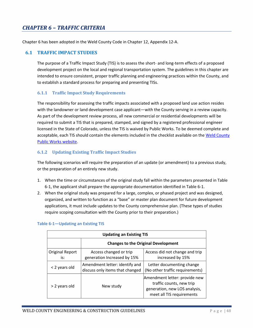
WELD COUNTY ENGINEERING & CONSTRUCTION GUIDELINES P a g e | 48
CHAPTER 6 – TRAFFIC CRITERIA
Chapter 6 has been adopted in the Weld County Code in Chapter 12, Appendix 12-A.
6.1 TRAFFIC IMPACT STUDIES
The purpose of a Traffic Impact Study (TIS) is to assess the short- and long-term effects of a proposed
development project on the local and regional transportation system. The guidelines in this chapter are
intended to ensure consistent, proper traffic planning and engineering practices within the County, and
to establish a standard process for preparing and presenting TISs.
6.1.1 Traffic Impact Study Requirements
The responsibility for assessing the traffic impacts associated with a proposed land use action resides
with the landowner or land development case applicant—with the County serving in a review capacity.
As part of the development review process, all new commercial or residential developments will be
required to submit a TIS that is prepared, stamped, and signed by a registered professional engineer
licensed in the State of Colorado, unless the TIS is waived by Public Works. To be deemed complete and
acceptable, each TIS should contain the elements included in the checklist available on the Weld County
Public Works website.
6.1.2 Updating Existing Traffic Impact Studies
The following scenarios will require the preparation of an update (or amendment) to a previous study,
or the preparation of an entirely new study.
1. When the time or circumstances of the original study fall within the parameters presented in Table
6-1, the applicant shall prepare the appropriate documentation identified in Table 6-1.
2. When the original study was prepared for a large, complex, or phased project and was designed,
organized, and written to function as a “base” or master plan document for future development
applications, it must include updates to the County comprehensive plan. (These types of studies
require scoping consultation with the County prior to their preparation.)
Table 6-1—Updating an Existing TIS
Updating an Existing TIS
Changes to the Original Development
Original Report is:
Access changed or trip generation Increased by 15%
Access did not change and trip increased by 15%
< 2 years old Amendment letter: identify and discuss only items that changed
Letter documenting change (No other traffic requirements)
> 2 years old New study
Amendment letter: provide new traffic counts, new trip
generation, new LOS analysis, meet all TIS requirements
WELD COUNTY ENGINEERING & CONSTRUCTION GUIDELINES P a g e | 49
6.2 TRAFFIC CONTROL DEVICES AND PLANS
All road signs, striping, delineators, barricades, signals, and other traffic control devices shall conform to
the MUTCD and any applicable Colorado supplement, as amended. The applicant shall be required to
install all necessary signage and shall bear all expenses for the fabrication and installation of road name
signs, permanent barricades, and signs for implementing the approved project design (e.g., one way, no
parking, no outlet, stop sign, speed limit). Necessary signage shall include signs required on County
roads as a consequence of the applicant’s project, such as regulatory, guide, or warning signs. Signs and
barricades shall be in place prior to road acceptance.
6.2.1 Striping and Signing Plans
All road improvement and/or land development projects must incorporate a separate signage and
striping plan in accordance with the criteria of this section. Striping plans may not be required for local
subdivision roads. However, sign plans are still required for all subdivisions. All signing and striping plans
shall conform to the most current edition of the MUTCD. All traffic control devices shall be fabricated
and installed in accordance with the MUTCD. Permanent signage and striping shall be complete and in
place before any new roadway is opened to the public for use.
Signing Plan Elements
1. Show the general longitudinal location of each sign (horizontal offset and station).
2. Specify the sign legend and sign type.
3. Specify the sign size.
Striping Plan Elements
1. Include stripe color and type.
2. Include lane width, taper lengths, storage lengths, etc.
3. Include striping/skip interval.
4. All pavement marking materials, except point location markings, must meet current CDOT
specifications for water-based traffic marking paint unless another material is specified by the
engineer.
5. All point location markings (stop bars, turn arrows, words, symbols, etc.) must meet specifications.
6. Include station and offset or dimensions for all angle points, symbol locations, and line
terminations.
7. Include stripe dimensions.
8. Delineate raised median islands.
6.2.2 Type and Location of Signs
The Department of Public Works shall make the final determination regarding the type and location of
traffic control devices within the right-of-way or access easement. These controls shall include traffic
control signs, road name signs, delineators, and permanent barricades.
WELD COUNTY ENGINEERING & CONSTRUCTION GUIDELINES P a g e | 50
6.2.3 New Roadway Signage
Permanent signage, unless otherwise approved by the Department of Public Works, shall be installed
before any new road or access easement is opened for use.
6.3 ACCESS CONTROL PLAN
Weld County recognizes that property owners have a right of reasonable access to the County road
system. However, within an environment where population growth will increase traffic volumes and
operational pressure on the general transportation system, be it rural or urban, access control is crucial
to protect the public health, safety, and welfare. Access control is used to maintain smooth traffic flow,
to provide road right-of-way drainage, and to protect the functional level of the County roads while
meeting state, regional, local, and private transportation needs and interests. Weld County Code Sec.
12-5-10, et seq., contains the County’s Road Access Policy.
Access spacing criteria for local roads, collector roads, and arterial roads are shown in Table 6-2.
Table 6-2 Minimum Access Spacing Criteria (feet)
Access Element Arterial Collector Local
Distance between intersections Signalized 2,640 N/A N/A
Unsignalized 1,320 1,320 330
Distance between accesses and intersections 660 660 330
Distance between access points 660 330 150
Distance between access points in subdivisions 660 330 75
6.3.1 Local Roadways
Access standards to local roadways shall be governed by Table 6-2. Whenever possible, shared accesses
will be given priority.
6.3.2 Collector Roadways
Access standards to collectors are shown in Table 6-2. An access or new intersection onto a collector is
not permitted unless it meets the spacing requirements in Table 6-2 and an alternative access or
intersection to a lower classified road is not feasible. No more than one access shall be allowed to an
individual or to contiguous parcels under the same ownership unless it can be shown that: the
additional access would not be in conflict with local safety regulations; the additional access would not
be detrimental to public health, safety, and welfare; and the additional access is necessary for the
efficient use of the property.
6.3.3 Arterial Roadways
Access standards onto arterial roadways are shown in Table 6-2. An access or new intersection onto an
arterial is not permitted unless an access/intersection to a lower classified road is not feasible and the
proposed access meets the spacing requirements in Table 6-2 and does not interfere with the location,
WELD COUNTY ENGINEERING & CONSTRUCTION GUIDELINES P a g e | 51
planning, and operation of the general street system or access to nearby properties. Whenever possible,
shared accesses will be given priority. No more than one access shall be allowed to an individual or to
contiguous parcels under the same ownership unless it can be shown that that: allowing only one access
would be in conflict with local safety regulations; the additional access would not be detrimental to
public health, safety, and welfare; and the additional access is necessary for the efficient use of the
property. Intersections shall be spaced no less than 0.5-mile apart on arterials, unless such spacing is
impractical or impossible due to topographic or other physical limitations as determined by the
Department of Public Works. The type of access—full movement, three-quarter movement, or right-in
right-out movement—will be determined by the Department of Public Works.
6.3.4 State Highway and Interstate Systems
CDOT and FHWA rules and regulations shall apply to all highway and interstate accesses. Weld County
takes no jurisdictional authority over access onto a highway or interstate.
6.3.5 Shared Accesses
Whenever possible and feasible, shared access will be provided to serve two or more adjacent
properties. Shared access is to be centered on the common property line. For shared accesses, Public
Works strongly recommends the property owner establish a written access road maintenance
agreement so future owners of the properties will be aware of their requirements for shared
maintenance of the access road. Shared access points or easements shall be a minimum of 30 feet wide
and shall contain a minimum 20-foot-wide, all-weather roadway.
6.4 ACCESS DESIGN
Access points shall be designed to provide safe movement for traffic entering and traveling on roadways
within the County. Like intersections, access points are conflict locations. The basic design of access
points includes adequate spacing, proper alignments, and clear sight distances.
6.4.1 Geometric Design
Accesses shall enter onto Weld County roads at an 80- to 100-degree angle, for a minimum of one
vehicle length. An access approach that is gated shall be designed so that the longest vehicle (including
trailers) using the access can completely clear the traveled way when the gate is closed. In no event shall
the distance from the gate to the edge of the traveled surface be less than 35 feet. Any overhead entry
structures shall have at least a 13’ 6” clearance, measured from the access surface. When the access is
intended for commercial or industrial use, the access radii shall accommodate the turning movements of
anticipated vehicle types. The following are the access width and access radii for properties based upon
land use.
Type of Land Use Access Width Access Radii Single-family residential 20-24 feet wide 25 feet minimum Commercial/Industrial 24-36 feet wide 60 feet minimum Fill slopes and cut slopes shall be constructed to match the slopes of the existing County road adjacent
to the access. It is desirable that all side slopes be no steeper than 3:1(H:V). If a drainage culvert is
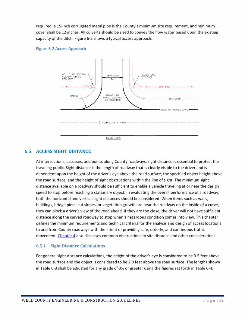
WELD COUNTY ENGINEERING & CONSTRUCTION GUIDELINES P a g e | 52
required, a 15-inch corrugated metal pipe is the County’s minimum size requirement, and minimum
cover shall be 12 inches. All culverts should be sized to convey the flow water based upon the existing
capacity of the ditch. Figure 6-2 shows a typical access approach.
Figure 6-2 Access Approach
6.5 ACCESS SIGHT DISTANCE
At intersections, accesses, and points along County roadways, sight distance is essential to protect the
traveling public. Sight distance is the length of roadway that is clearly visible to the driver and is
dependent upon the height of the driver's eye above the road surface, the specified object height above
the road surface, and the height of sight obstructions within the line of sight. The minimum sight
distance available on a roadway should be sufficient to enable a vehicle traveling at or near the design
speed to stop before reaching a stationary object. In evaluating the overall performance of a roadway,
both the horizontal and vertical sight distances should be considered. When items such as walls,
buildings, bridge piers, cut slopes, or vegetation growth are near the roadway on the inside of a curve,
they can block a driver’s view of the road ahead. If they are too close, the driver will not have sufficient
distance along the curved roadway to stop when a hazardous condition comes into view. This chapter
defines the minimum requirements and technical criteria for the analysis and design of access locations
to and from County roadways with the intent of providing safe, orderly, and continuous traffic
movement. Chapter 4 also discusses common obstructions to site distance and other considerations.
6.5.1 Sight Distance Calculations
For general sight distance calculations, the height of the driver's eye is considered to be 3.5 feet above
the road surface and the object is considered to be 2.0 feet above the road surface. The lengths shown
in Table 6-3 shall be adjusted for any grade of 3% or greater using the figures set forth in Table 6-4.

WELD COUNTY ENGINEERING & CONSTRUCTION GUIDELINES P a g e | 53
Table 6-3 Minimum Sight Distance along Roadway (Horizontal and Vertical)
Minimum Sight Distance along the Roadway (Horizontal & Vertical)
Posted speed (MPH) 25 30 35 40 45 50 55 60 65 70
Design sight distance (ft) 150 200 250 325 400 475 550 650 725 850
Minimum sight distance (ft)1,2 150 200 225 275 325 400 450 525 550 625 1. To calculate sight distance at the proposed access location, a height of 3.5 feet shall be used for the driver's eyes of a vehicle on
the highway approaching the access location. The driver's eyes shall be assumed to be at the centerline of the inside lane (inside with respect to the curve) for measurement purposes. A height of 3.5 feet shall be used for a vehicle assumed to be on the centerline of the access 5 feet back from the edge of the travel lane.
2. If an auxiliary lane is present, the entering posted speed for the deceleration lane and the posted speed at the end of the acceleration lane shall be used.
Table 6-4 Sight Distance Adjustment Factors for Roadway Grade
Sight Distance Adjustment Factors for Roadway Grade
Roadway Grade Factors
Upgrade
3% to 4.9 % 0.90
5% to 7.5 % 0.80
Downgrade 3% to 4.9 % 1.20
5% to 7.5 % 1.35
6.6.2 Stopping Sight Distance
The minimum stopping sight distance is the distance required by the driver of a vehicle traveling at the
design speed to bring the vehicle to a stop after an object on the road becomes visible. Stopping sight
distance is the sum of the braking distance and the brake reaction time (the interval between the instant
that the driver recognizes the existence of an object on the roadway and the instant the driver applies
the brakes). The braking distance is related to the initial speed and the coefficient of friction between
the tires and the roadway. The wet condition governs the stopping distances for purposes of design.
Table 6-5 provides the required minimum stopping sight distances on straight roadways with grades of
less than 3%. In no case shall the stopping sight distance be less than as specified in Table 6-5. For
grades in excess of 3%, refer to Table 6-6. For stopping sight distance calculations, the height of the
object is considered to be 6 inches above the road surface. Chapter 4 provides additional information
concerning roadway design and stopping sight distance.
WELD COUNTY ENGINEERING & CONSTRUCTION GUIDELINES P a g e | 54
Table 6-5 Stopping Sight Distances
Stopping Sight Distances
Design Speed (MPH)
Brake Reaction
Distance (ft)1
Braking Distance on
Level (ft)
Stopping Sight Distance
Calculated (ft) Design (ft)
25 91.9 60.0 151.9 155
30 110.3 86.4 196.7 200
40 147.0 153.6 300.6 305
50 183.8 240.0 423.8 425
60 220.5 345.5 566.0 570
70 257.3 470.3 727.6 730 1. Brake reaction distance predicted on a time of 2.5 seconds; deceleration rate of 11.2 feet/second used to determine calculated sight distance.
Table 6-6 Stopping Distance at Grade
Stopping Distance at Grade
Design Speed (MPH)
Downgrades
Design Speed (MPH)
Upgrades
Stopping Distance (ft)
Stopping Distance (ft)
3% 6% 9% 3% 6% 9%
25 158 165 173 25 147 143 140
30 205 215 227 30 200 184 179
40 315 333 354 40 289 278 269
50 446 474 507 50 405 388 375
60 598 638 686 60 538 515 495
70 771 825 891 70 690 658 631
6.5.3 Stopping Sight Distance at Grade
When a roadway is constructed on a grade steeper than 3%, the braking distance should not only
account for the initial speed and coefficient of friction, but should also be adjusted accounting for the
percent grade (both up and down). Table 6-6 provides the required stopping sight distances at grade in
wet conditions.
6.5.4 Stopping Sight Distance on Horizontal Curves
The proposed horizontal alignment must provide for the minimum stopping distance for the design
speed at all points along the roadway. In addition, the design must take into account the visibility at
intersections, around curves, and at roadside encroachments. Stopping sight distance on horizontal
curves is based on lateral clearance from the inner edge of the pavement to the sight obstruction, for
various radii of inner edge of pavement and design speeds. The position of the driver’s eye and the
object sighted shall be assumed to be 6 feet from the inner edge of the pavement, with the sight
distance being measured along this arc.
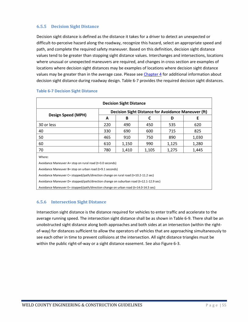
WELD COUNTY ENGINEERING & CONSTRUCTION GUIDELINES P a g e | 55
6.5.5 Decision Sight Distance
Decision sight distance is defined as the distance it takes for a driver to detect an unexpected or
difficult-to-perceive hazard along the roadway, recognize this hazard, select an appropriate speed and
path, and complete the required safety maneuver. Based on this definition, decision sight distance
values tend to be greater than stopping sight distance values. Interchanges and intersections, locations
where unusual or unexpected maneuvers are required, and changes in cross section are examples of
locations where decision sight distances may be examples of locations where decision sight distance
values may be greater than in the average case. Please see Chapter 4 for additional information about
decision sight distance during roadway design. Table 6-7 provides the required decision sight distances.
Table 6-7 Decision Sight Distance
Decision Sight Distance
Design Speed (MPH) Decision Sight Distance for Avoidance Maneuver (ft)
A B C D E
30 or less 220 490 450 535 620
40 330 690 600 715 825
50 465 910 750 890 1,030
60 610 1,150 990 1,125 1,280
70 780 1,410 1,105 1,275 1,445
Where:
Avoidance Maneuver A= stop on rural road (t=3.0 seconds)
Avoidance Maneuver B= stop on urban road (t=9.1 seconds)
Avoidance Maneuver C= stopped/path/direction change on rural road (t=10.2-11.2 sec)
Avoidance Maneuver D= stopped/path/direction change on suburban road (t=12.1-12.9 sec)
Avoidance Maneuver E= stopped/path/direction change on urban road (t=14.0-14.5 sec)
6.5.6 Intersection Sight Distance
Intersection sight distance is the distance required for vehicles to enter traffic and accelerate to the
average running speed. The intersection sight distance shall be as shown in Table 6-9. There shall be an
unobstructed sight distance along both approaches and both sides at an intersection (within the right-
of-way) for distances sufficient to allow the operators of vehicles that are approaching simultaneously to
see each other in time to prevent collisions at the intersection. All sight distance triangles must be
within the public right-of-way or a sight distance easement. See also Figure 6-3.

WELD COUNTY ENGINEERING & CONSTRUCTION GUIDELINES P a g e | 56
Table 6-8 Intersection Sight Distance
Intersection Sight Distance
Crossroad Posted Speed Limit
(MPH)
Required Sight Distance (ft)
Clear Zone Length Left
(ft)
Clear Zone Length Right
(ft)
20 200 108 74
25 275 148 101
30 350 188 129
35 425 229 157
40 500 269 184
45 575 310 212
50 650 350 239
55 725 390 267
Figure 6-3
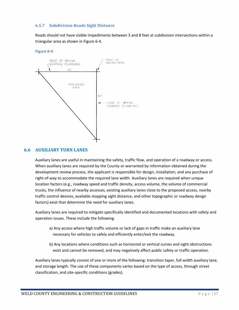
WELD COUNTY ENGINEERING & CONSTRUCTION GUIDELINES P a g e | 57
6.5.7 Subdivision Roads Sight Distance
Roads should not have visible impediments between 3 and 8 feet at subdivision intersections within a
triangular area as shown in Figure 6-4.
Figure 6-4
6.6 AUXILIARY TURN LANES
Auxiliary lanes are useful in maintaining the safety, traffic flow, and operation of a roadway or access.
When auxiliary lanes are required by the County or warranted by information obtained during the
development review process, the applicant is responsible for design, installation, and any purchase of
right-of-way to accommodate the required lane width. Auxiliary lanes are required when unique
location factors (e.g., roadway speed and traffic density, access volume, the volume of commercial
trucks, the influence of nearby accesses, existing auxiliary lanes close to the proposed access, nearby
traffic control devices, available stopping sight distance, and other topographic or roadway design
factors) exist that determine the need for auxiliary lanes.
Auxiliary lanes are required to mitigate specifically identified and documented locations with safety and
operation issues. These include the following.
a) Any access where high traffic volume or lack of gaps in traffic make an auxiliary lane
necessary for vehicles to safely and efficiently enter/exit the roadway.
b) Any locations where conditions such as horizontal or vertical curves and sight obstructions
exist and cannot be removed, and may negatively affect public safety or traffic operation.
Auxiliary lanes typically consist of one or more of the following: transition taper, full width auxiliary lane,
and storage length. The use of these components varies based on the type of access, through street
classification, and site-specific conditions (grades).
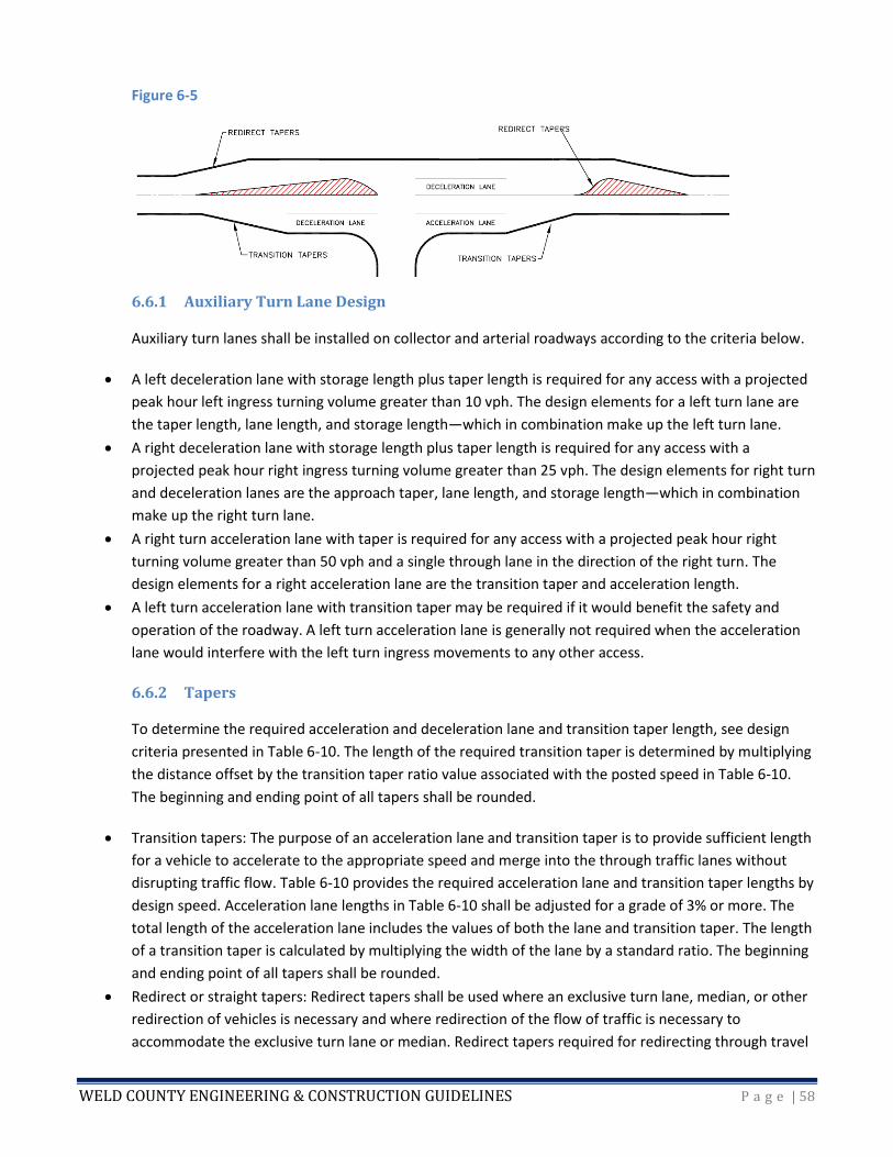
WELD COUNTY ENGINEERING & CONSTRUCTION GUIDELINES P a g e | 58
Figure 6-5
6.6.1 Auxiliary Turn Lane Design
Auxiliary turn lanes shall be installed on collector and arterial roadways according to the criteria below.
• A left deceleration lane with storage length plus taper length is required for any access with a projected
peak hour left ingress turning volume greater than 10 vph. The design elements for a left turn lane are
the taper length, lane length, and storage length—which in combination make up the left turn lane.
• A right deceleration lane with storage length plus taper length is required for any access with a
projected peak hour right ingress turning volume greater than 25 vph. The design elements for right turn
and deceleration lanes are the approach taper, lane length, and storage length—which in combination
make up the right turn lane.
• A right turn acceleration lane with taper is required for any access with a projected peak hour right
turning volume greater than 50 vph and a single through lane in the direction of the right turn. The
design elements for a right acceleration lane are the transition taper and acceleration length.
• A left turn acceleration lane with transition taper may be required if it would benefit the safety and
operation of the roadway. A left turn acceleration lane is generally not required when the acceleration
lane would interfere with the left turn ingress movements to any other access.
6.6.2 Tapers
To determine the required acceleration and deceleration lane and transition taper length, see design
criteria presented in Table 6-10. The length of the required transition taper is determined by multiplying
the distance offset by the transition taper ratio value associated with the posted speed in Table 6-10.
The beginning and ending point of all tapers shall be rounded.
• Transition tapers: The purpose of an acceleration lane and transition taper is to provide sufficient length
for a vehicle to accelerate to the appropriate speed and merge into the through traffic lanes without
disrupting traffic flow. Table 6-10 provides the required acceleration lane and transition taper lengths by
design speed. Acceleration lane lengths in Table 6-10 shall be adjusted for a grade of 3% or more. The
total length of the acceleration lane includes the values of both the lane and transition taper. The length
of a transition taper is calculated by multiplying the width of the lane by a standard ratio. The beginning
and ending point of all tapers shall be rounded.
• Redirect or straight tapers: Redirect tapers shall be used where an exclusive turn lane, median, or other
redirection of vehicles is necessary and where redirection of the flow of traffic is necessary to
accommodate the exclusive turn lane or median. Redirect tapers required for redirecting through travel

WELD COUNTY ENGINEERING & CONSTRUCTION GUIDELINES P a g e | 59
lanes shall be installed in conformance with Table 6-10. If the redirect taper would result in a horizontal
curve design deficiency for the through movement, the horizontal curve shall be corrected. Redirect
tapers should be designed as straight tapers with the beginning and ending points rounded.
Table 6-10 Acceleration/Deceleration Lane Design Criteria
Acceleration/Deceleration Lane Design Criteria
Posted speed limit (MPH) 25 30 35 40 45 50 55
Deceleration length (ft) 180 250 310 370 435 500 600
Acceleration length (ft) N/A 190 270 380 550 760 960
Transition taper (ratio) 7.5:1 8:1 10:1 12:1 13.5:1 15:1 18.5:1
Straight taper (ratio) 15:1 15:1 20:1 30:1 45:1 50:1 55:1
6.6.3 Storage Lengths
The storage length for an auxiliary lane can be determined by the information summarized in Table 6-11.
These lengths are based on the average length of a passenger vehicle and the estimated turning vehicles
per hour. Estimated lengths for buses, larger trucks, and recreational vehicles must be determined and
submitted to the County for review.
Table 6-11 Auxiliary Lane Storage Lengths
Auxiliary Lane Storage Lengths
Turning vehicles per hour <30 30-59 60-100 >100
Minimum required storage length (ft) 25 40 50 100
The basis for designing the length of required storage is to provide sufficient length for vehicles to queue
within the lane without affecting other movements. Table 6-10 provides the required storage lengths for
stop-controlled intersections. Table 6-11 provides the required calculated storage lengths for signal-
controlled intersections. If the Department of Public Works determines that meeting the required
storage length is impractical or will result in an unsafe condition, the minimum storage length shall be
based on the mean arrival rate. But in no case shall the minimum auxiliary lane length be less than 50
feet.
6.6.4 Auxiliary Lane Conflicts
The following are additional standards for auxiliary lane design.
1. No driveway shall be permitted within the transition area of any auxiliary lane.
2. In the event that a portion of an auxiliary lane extends across one or more adjacent properties, the
County may require the applicant to obtain any necessary right-of-way.
3. In the event an auxiliary lane is constructed within 100 feet of an arterial-arterial intersection, the
applicant is responsible for design, acquisition of required right-of-way, relocation of utilities, and
construction of the lane to such intersection.
WELD COUNTY ENGINEERING & CONSTRUCTION GUIDELINES P a g e | 60
4. Where two intersections have exclusive turn lanes that overlap or the ending points of the exclusive
turn lanes have less than 300 feet or one-half their length of separation (whichever is shorter), and a
significant structure or topographical feature does not preclude widening, a continuous exclusive
turn lane shall be constructed between the intersections to improve roadway consistency and
safety, and to maintain edge of pavement continuity.
5. If restrictive topography allows only one exclusive turn lane, normally a left turn deceleration lane is
given first priority. Where a left turn lane is installed and the travel lanes must be redirected, an
overlay of pavement is required.
6.7 ACCESS CONSTRUCTION
All roadway access construction which affects existing structures within the County right-of-way—such
as pavement, curbs, gutters, sidewalks, drainage structures, ditches, and auxiliary lanes—is required to
incorporate modifications to existing structures as part of the final access design. A Right-of-Way Permit
is required prior to any new construction in Weld County rights-of-way.
6.7.1 Gravel Requirements
Gravel or recycled asphalt gravel base will be permitted for individual residential access or field access
adjacent to county roads with gravel surfacing. The gravel surface will include a minimum of 4 inches of
compacted aggregate base course or equivalent material from the right-of-way line to the edge of the
traveled roadway.
6.7.2 Pavement Requirements
Access pavement thickness shall match roadway pavement thickness. If required by the weather, a delay
of one season in placement of hot bituminous pavement may be allowed, provided adequate gravel
surfacing is substituted and maintained until asphalt placement.
6.7.3 Access Drainage
Accesses should be constructed in a manner that minimizes erosion and does not result in deposition of
silt and debris upon the County roadway or roadside ditches. Accesses which slope down toward the
public road will be constructed to assure that water does not run onto or across the traveled public way.
This may include designing the crown; borrow ditches, pans, or other elements so that they direct water
to the existing drainage facilities along the road. The owner of the property shall pay for materials and
the cost of installation for new access culverts whenever the installation of a culvert is made necessary
by the creation of a new access from private property to a County roadway. The applicant is responsible
for any alterations of the natural flow of water across private properties.
6.7.4 Structures
For efficiency and to avoid maintenance or public safety concerns, the County reserves the right to
maintain the full width of the road right-of-way without structures located thereon. Structures include,
but are not limited to: fences, trash cans, gates, mailboxes, and irrigation structures regardless of
whether or not they are physically located on the traveled portion or right-of-way. Structures shall be
WELD COUNTY ENGINEERING & CONSTRUCTION GUIDELINES P a g e | 61
removed from the right-of-way upon written request by the Department of Public Works. Mailboxes
may be located in the public road right-of-way only where they do not create a roadside hazard,
obstruct or hinder vehicular or pedestrian traffic, or interfere with road maintenance activities such as
snowplowing and mowing. Mailboxes shall be located at least 8 feet away from the edge of the traveled
way.
Wear, damage, or breakage to mailboxes, fencing, decorative items, signage, or any other
appurtenances throughout the property roadside frontage due to thrown snow and inclusions from
snow removal activities on a County-maintained road will not be the responsibility of the County.
6.8 CHANGE IN ACCESS USE
If the use of an existing access to County right-of-way changes or there is a change in the use of the
property, a new Access Permit may be required, in accordance with Chapter 12 Article 5 of the Weld
County Code. Change in access or property use may include, but is not limited to: change in the amount
or type of traffic; structural modification; remodeling; change in use or type of business; expansion of
existing business; change in zoning; change in property division; and creation of new parcels.
6.9 TEMPORARY ACCESS
Any road access which will be closed after being used for a limited time may be considered a temporary
road access. The time in use of temporary accesses shall not exceed twelve months. A Temporary Access
Permit may be granted only if the temporary access meets minimum County traffic safety and
operational requirements, including sight distance.
6.10 TRACKING CONTROL
The following are minimal standards that require tracking control devices:
• Less than 20 passenger vehicle round trips/day, no upfront tracking control requirements.
• 20 to 50 passenger vehicle round trips/day or less than 4 truck round trips/day:
o Access onto gravel roads includes 50 feet of road base or recycled asphalt.
o Access onto paved roads includes 100 feet of road base or recycled asphalt.
• 4 to 10 round truck trips/day (tandem or semi-trucks):
o Access onto gravel roads requires recycled asphalt or road base on all driving surfaces.
o Access onto paved roads requires a tracking control device and a minimum of 100 feet of
recycled asphalt/road base OR 300 feet of asphalt. (Surface improvements less than 300 feet
may be allowed if site constraints would prohibit meeting condition.)
• More than 10 round truck trips/day (tandem or semi-trucks) or more than 50 round passenger vehicles
trips:
WELD COUNTY ENGINEERING & CONSTRUCTION GUIDELINES P a g e | 62
o Access onto gravel roads requires a tracking control device and a minimum of 300 feet of
recycled asphalt or road base.
o Access onto paved roads requires both a tracking control devise and 100 feet of asphalt OR 300
feet of asphalt.
6.10.1 Tracking Control Devices
To mitigate any impacts to the public road including damages and/or offsite tracking of mud or other
materials. The following is a list of possible tracking control devices that can be potential combined or
used individually:
o Cattle Guards.
o Asphalt or Concrete paving.
o Rip-Rap (6" washed rock).

WELD COUNTY ENGINEERING & CONSTRUCTION GUIDELINES P a g e | 63
CHAPTER 7 – SOIL INVESTIGATION AND PAVEMENT DESIGN
7.1 INTRODUCTION AND PURPOSE
The design of a pavement structure involves the consideration of many factors and conditions. The most
important being traffic volumes, vehicle classifications, design materials, existing materials, and local
climate and drainage conditions. The purpose of this chapter is to give general guidance to the users and
to supplement the existing design information contained within the latest editions of the Colorado
Department of Transportation Pavement Design Manual and M-E Pavement Design Manual as well as
AASHTO or ASTM Material Manuals. These criteria provide the basic design procedures and reporting
guidelines for Flexible Pavements. The final design should be based on a thorough investigation of
specific project conditions, projected traffic, life-cycle economics, and on the performance of
comparable projects with similar structural sections under similar conditions. An adequate pavement
design will reduce long-term maintenance costs and provide a long-lasting driving surface.
7.2 FIELD INVESTIGATION AND SOIL SAMPLES
Designers should visit each site to gather information that may help determine the appropriate design.
Whether this is a new design or rehabilitation of an existing pavement, information such as current
distress, drainage conditions, roughness, traffic control options, and surrounding land usage should be
collected and will be used later during the actual design.
7.2.1 Testing Frequency
Soil samples within the project limits shall be obtained for each soil type as defined in the Soil Survey of
Weld County, Colorado (http://websoilsurvey.nrcs.usda.gov/app/) or at a spacing of not more than 500
linear feet.
7.2.2 Sampling Procedures
Borings can be performed by either an auger or core drill. The depth of each hole should generally be at
least 5 feet to 10 feet, depending upon the anticipated depths of cuts or fills of a new roadway. Borings
for rehabilitation of existing surfaces can generally be on the lower range unless major reconstructions
are necessary at certain locations. All borings shall be field logged and visually classified.
7.3 SUBGRADE TESTING
7.3.1 Classification
Each boring location shall be tested to determine liquid limit, plastic limit, plasticity index, and the
percentage passing the U.S. Standard No. 200 sieve. Test results shall be used to calculate the AASHTO
Classification and Group Index using AASHTO M 145.
These data shall be determined using the following methods:
• Liquid limit: AASHTO T 89 or ASTM D 4318
• Plastic limit: AASHTO T 90 or ASTM D 4318
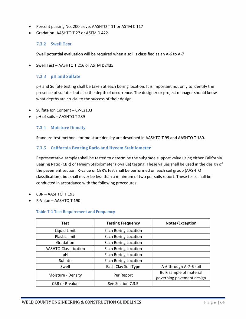
WELD COUNTY ENGINEERING & CONSTRUCTION GUIDELINES P a g e | 64
• Percent passing No. 200 sieve: AASHTO T 11 or ASTM C 117
• Gradation: AASHTO T 27 or ASTM D 422
7.3.2 Swell Test
Swell potential evaluation will be required when a soil is classified as an A-6 to A-7
• Swell Test – AASHTO T 216 or ASTM D2435
7.3.3 pH and Sulfate
pH and Sulfate testing shall be taken at each boring location. It is important not only to identify the
presence of sulfates but also the depth of occurrence. The designer or project manager should know
what depths are crucial to the success of their design.
• Sulfate Ion Content – CP-L2103
• pH of soils – AASHTO T 289
7.3.4 Moisture Density
Standard test methods for moisture density are described in AASHTO T 99 and AASHTO T 180.
7.3.5 California Bearing Ratio and Hveem Stabilometer
Representative samples shall be tested to determine the subgrade support value using either California
Bearing Ratio (CBR) or Hveem Stabilometer (R-value) testing. These values shall be used in the design of
the pavement section. R-value or CBR’s test shall be performed on each soil group (AASHTO
classification), but shall never be less than a minimum of two per soils report. These tests shall be
conducted in accordance with the following procedures:
• CBR – AASHTO T 193
• R-Value – AASHTO T 190
Table 7-1 Test Requirement and Frequency
Test Testing Frequency Notes/Exception
Liquid Limit Each Boring Location
Plastic limit Each Boring Location
Gradation Each Boring Location
AASHTO Classification Each Boring Location
pH Each Boring Location
Sulfate Each Boring Location
Swell Each Clay Soil Type A-6 through A-7-6 soil
Moisture - Density Per Report Bulk sample of material
governing pavement design
CBR or R-value See Section 7.3.5
WELD COUNTY ENGINEERING & CONSTRUCTION GUIDELINES P a g e | 65
7.4 PAVEMENT DESIGN CRITERIA
Weld County’s pavement design method is based on the 1993 AASHTO Design Guide Equations and
CDOT guidelines. This section provides the criteria used for the design of pavements in Weld County.
These criteria will ensure adequate strength and durability to carry the predicted traffic loads for the
design life of each project. Alternative designs will be considered as advances are made in pavement
design methods and paving materials. Any deviation from the guidelines presented in this document
must be technically justified and approved by the Public Works Department. Weld County does not
recommend the use of full-depth asphalt paving and does not accept maintenance of any full-depth
paved roads.
7.4.1 Design Equivalent Single Axle Loads (ESAL)
There are certain input requirements needed to obtain an 18,000-pound Equivalent Single Axle Load
calculation or design ESAL.
• Average daily traffic count (ADT)
• Vehicle classification
• Traffic equivalence load factors
• Traffic growth rate
• Design period
• Lane factor
7.4.2 Average Daily Traffic (ADT) Count
Volume counts are expressed as ADT counts or Annual Average Daily Traffic (AADT) counts. ADT is a 24-
hour, two-way, daily traffic count. AADT is the annual average two-way daily traffic volume. It
represents the total traffic on a section of roadway for the year, divided by 365, including both
weekdays and weekend traffic volumes. The count is given in vehicles per day. To be valid and represent
actual volumes, the traffic count should be no more than one year old. If known changes to the traffic
volumes exist since the latest count, such as new development or changes to existing development that
could modify the counts, then a new traffic count may be warranted. The traffic count cannot be a raw
volume count; it must include a vehicle classification.
7.4.3 Vehicle Classification
Vehicle classification categorizes vehicles into three types.
• Lightweight vehicles: All motorcycles, cars, pickups, vans and single/dual wheels
• Single units: Buses and other units up to three axles
• Combo units: Vehicles of four axles and more
Figure 7-1 shows the most common types of vehicles found on the nation’s highways. Designers can use
this information to determine which vehicle classification category should be used for the vehicles
identified in the traffic count.
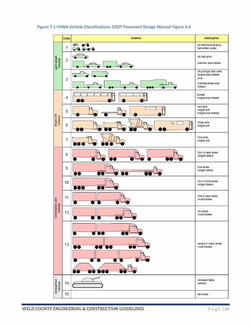
WELD COUNTY ENGINEERING & CONSTRUCTION GUIDELINES P a g e | 66
Figure 7-1 FHWA Vehicle Classifications CDOT Pavement Design Manual Figure 3.4
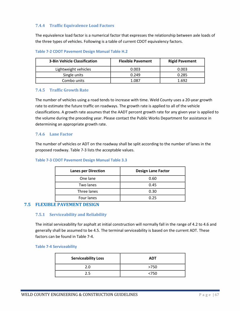
WELD COUNTY ENGINEERING & CONSTRUCTION GUIDELINES P a g e | 67
7.4.4 Traffic Equivalence Load Factors
The equivalence load factor is a numerical factor that expresses the relationship between axle loads of
the three types of vehicles. Following is a table of current CDOT equivalency factors.
Table 7-2 CDOT Pavement Design Manual Table H.2
3-Bin Vehicle Classification Flexible Pavement Rigid Pavement
Lightweight vehicles 0.003 0.003
Single units 0.249 0.285
Combo units 1.087 1.692
7.4.5 Traffic Growth Rate
The number of vehicles using a road tends to increase with time. Weld County uses a 20-year growth
rate to estimate the future traffic on roadways. The growth rate is applied to all of the vehicle
classifications. A growth rate assumes that the AADT percent growth rate for any given year is applied to
the volume during the preceding year. Please contact the Public Works Department for assistance in
determining an appropriate growth rate.
7.4.6 Lane Factor
The number of vehicles or ADT on the roadway shall be split according to the number of lanes in the
proposed roadway. Table 7-3 lists the acceptable values.
Table 7-3 CDOT Pavement Design Manual Table 3.3
Lanes per Direction Design Lane Factor
One lane 0.60
Two lanes 0.45
Three lanes 0.30
Four lanes 0.25
7.5 FLEXIBLE PAVEMENT DESIGN
7.5.1 Serviceability and Reliability
The initial serviceability for asphalt at initial construction will normally fall in the range of 4.2 to 4.6 and
generally shall be assumed to be 4.5. The terminal serviceability is based on the current ADT. These
factors can be found in Table 7-4.
Table 7-4 Serviceability
Serviceability Loss ADT
2.0 >750
2.5 <750
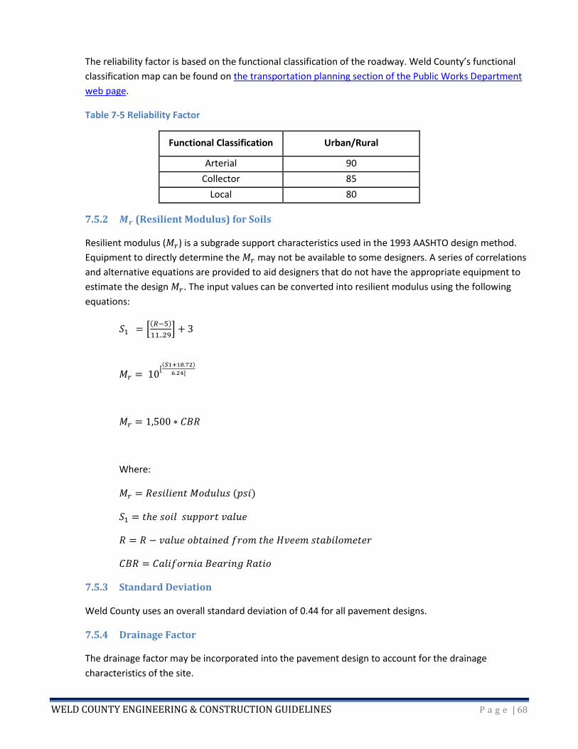
WELD COUNTY ENGINEERING & CONSTRUCTION GUIDELINES P a g e | 68
The reliability factor is based on the functional classification of the roadway. Weld County’s functional
classification map can be found on the transportation planning section of the Public Works Department
web page.
Table 7-5 Reliability Factor
Functional Classification Urban/Rural
Arterial 90
Collector 85
Local 80
7.5.2 𝑴𝒓 (Resilient Modulus) for Soils
Resilient modulus (𝑀𝑟) is a subgrade support characteristics used in the 1993 AASHTO design method.
Equipment to directly determine the 𝑀𝑟 may not be available to some designers. A series of correlations
and alternative equations are provided to aid designers that do not have the appropriate equipment to
estimate the design 𝑀𝑟. The input values can be converted into resilient modulus using the following
equations:
𝑆1 = [
(𝑅−5)
11..29] + 3
𝑀𝑟 = 10 [(𝑆1+18.72)
6.24]
𝑀𝑟 = 1,500 ∗ 𝐶𝐵𝑅
Where:
𝑀𝑟 = 𝑅𝑒𝑠𝑖𝑙𝑖𝑒𝑛𝑡 𝑀𝑜𝑑𝑢𝑙𝑢𝑠 (𝑝𝑠𝑖)
𝑆1 = 𝑡ℎ𝑒 𝑠𝑜𝑖𝑙 𝑠𝑢𝑝𝑝𝑜𝑟𝑡 𝑣𝑎𝑙𝑢𝑒
𝑅 = 𝑅 − 𝑣𝑎𝑙𝑢𝑒 𝑜𝑏𝑡𝑎𝑖𝑛𝑒𝑑 𝑓𝑟𝑜𝑚 𝑡ℎ𝑒 𝐻𝑣𝑒𝑒𝑚 𝑠𝑡𝑎𝑏𝑖𝑙𝑜𝑚𝑒𝑡𝑒𝑟
𝐶𝐵𝑅 = 𝐶𝑎𝑙𝑖𝑓𝑜𝑟𝑛𝑖𝑎 𝐵𝑒𝑎𝑟𝑖𝑛𝑔 𝑅𝑎𝑡𝑖𝑜
7.5.3 Standard Deviation
Weld County uses an overall standard deviation of 0.44 for all pavement designs.
7.5.4 Drainage Factor
The drainage factor may be incorporated into the pavement design to account for the drainage
characteristics of the site.
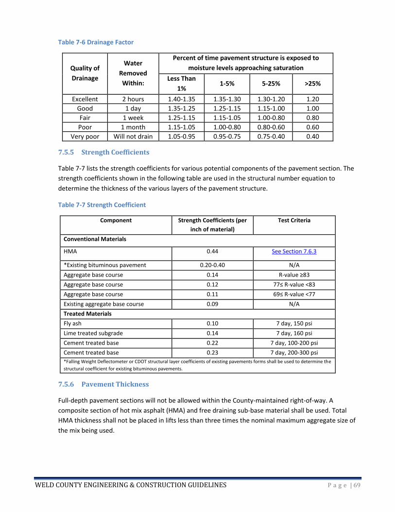
WELD COUNTY ENGINEERING & CONSTRUCTION GUIDELINES P a g e | 69
Table 7-6 Drainage Factor
Quality of
Drainage
Water
Removed
Within:
Percent of time pavement structure is exposed to
moisture levels approaching saturation
Less Than
1% 1-5% 5-25% >25%
Excellent 2 hours 1.40-1.35 1.35-1.30 1.30-1.20 1.20
Good 1 day 1.35-1.25 1.25-1.15 1.15-1.00 1.00
Fair 1 week 1.25-1.15 1.15-1.05 1.00-0.80 0.80
Poor 1 month 1.15-1.05 1.00-0.80 0.80-0.60 0.60
Very poor Will not drain 1.05-0.95 0.95-0.75 0.75-0.40 0.40
7.5.5 Strength Coefficients
Table 7-7 lists the strength coefficients for various potential components of the pavement section. The
strength coefficients shown in the following table are used in the structural number equation to
determine the thickness of the various layers of the pavement structure.
Table 7-7 Strength Coefficient
Component Strength Coefficients (per
inch of material)
Test Criteria
Conventional Materials
HMA 0.44 See Section 7.6.3
*Existing bituminous pavement 0.20-0.40 N/A
Aggregate base course 0.14 R-value ≥83
Aggregate base course 0.12 77≤ R-value <83
Aggregate base course 0.11 69≤ R-value <77
Existing aggregate base course 0.09 N/A
Treated Materials
Fly ash 0.10 7 day, 150 psi
Lime treated subgrade 0.14 7 day, 160 psi
Cement treated base 0.22 7 day, 100-200 psi
Cement treated base 0.23 7 day, 200-300 psi
*Falling Weight Deflectometer or CDOT structural layer coefficients of existing pavements forms shall be used to determine the
structural coefficient for existing bituminous pavements.
7.5.6 Pavement Thickness
Full-depth pavement sections will not be allowed within the County-maintained right-of-way. A
composite section of hot mix asphalt (HMA) and free draining sub-base material shall be used. Total
HMA thickness shall not be placed in lifts less than three times the nominal maximum aggregate size of
the mix being used.
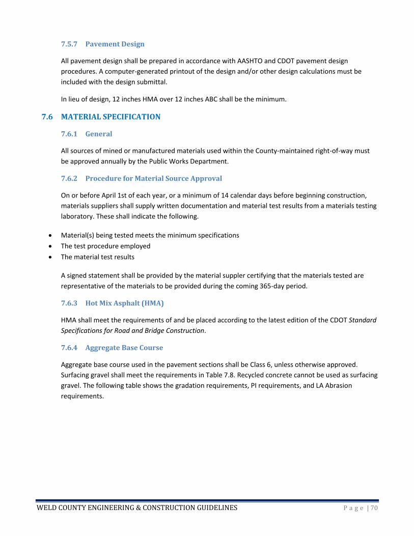
WELD COUNTY ENGINEERING & CONSTRUCTION GUIDELINES P a g e | 70
7.5.7 Pavement Design
All pavement design shall be prepared in accordance with AASHTO and CDOT pavement design
procedures. A computer-generated printout of the design and/or other design calculations must be
included with the design submittal.
In lieu of design, 12 inches HMA over 12 inches ABC shall be the minimum.
7.6 MATERIAL SPECIFICATION
7.6.1 General
All sources of mined or manufactured materials used within the County-maintained right-of-way must
be approved annually by the Public Works Department.
7.6.2 Procedure for Material Source Approval
On or before April 1st of each year, or a minimum of 14 calendar days before beginning construction,
materials suppliers shall supply written documentation and material test results from a materials testing
laboratory. These shall indicate the following.
• Material(s) being tested meets the minimum specifications
• The test procedure employed
• The material test results
A signed statement shall be provided by the material suppler certifying that the materials tested are
representative of the materials to be provided during the coming 365-day period.
7.6.3 Hot Mix Asphalt (HMA)
HMA shall meet the requirements of and be placed according to the latest edition of the CDOT Standard
Specifications for Road and Bridge Construction.
7.6.4 Aggregate Base Course
Aggregate base course used in the pavement sections shall be Class 6, unless otherwise approved.
Surfacing gravel shall meet the requirements in Table 7.8. Recycled concrete cannot be used as surfacing
gravel. The following table shows the gradation requirements, PI requirements, and LA Abrasion
requirements.
WELD COUNTY ENGINEERING & CONSTRUCTION GUIDELINES P a g e | 71
Table 7-8 Aggregate Base Course Requirements
Sieve Designation Mass Percent Passing Square Mesh Sieves
LL not greater than 35 LL not greater than 20 Gravel
Surfacing Standard
(mm)
Mesh
(in) Class 1 Class 2 Class 3 Class 4 Class 5 Class 6 Class 7
150.00 6 100
100.00 4 100
75.00 3 95-100
63.00 2.5 100
50.00 2 95-100 100
37.50 1.5 90-100 100 100
25.40 1 95-100 100 90-100
19.00 0.75 50-90 100
12.50 0.5 55-80
4.76 No. 4 30-65 30-50 30-70 30-65 45-65
2.38 No. 8 25-55 20-85 33-53
0.42 No. 40 15-35
0.07 No.
200
3-15 3-15 20 max 3-12 3-15 3-12 5-15 4-15
Plasticity index 0 0 0 0 0 0 0 4-12
LA wear test
(T96)
50
max
50
max
40 max
7.7 SOILS/PAVEMENT DESIGN REPORT
The soils/pavement design report shall include the following information.
1. Vicinity map of investigated area
2. Scaled drawing showing the location of borings
3. Scaled drawing showing the estimated extent of subgrade soil types, thickness of base material and
HMA
4. A spreadsheet showing all the factors used to calculate the design ESALs
5. Summary sheet listing all sample designations, liquid limit, plasticity index, percent passing the No.
200 sieve, AASHTO classifications, group index, soil description, CBR or R-value, moisture content,
percent soluble sulfate, and pH
6. A discussion regarding potential subgrade soil problems including, but not limited to: soils with
swelling potential, frost-susceptible soils, groundwater, drainage considerations (surface and
subsurface), cold weather construction (if appropriate), soluble sulfates and pH in the subgrade, and
other factors or properties that could affect the design or performance of the pavement system
7. Recommendations to alleviate or mitigate the impact of potential subgrade soil problems
8. Pavement design alternatives for roadway
9. Pavement mix types to be used for the project
WELD COUNTY ENGINEERING & CONSTRUCTION GUIDELINES P a g e | 72
10. Identify any deviations from the County criteria and discussion/justification for the deviation. A
formal request shall be submitted for approval of the design alternative.
11. The soils/pavement design report shall be signed and stamped by a registered professional engineer
licensed in the State of Colorado.
7.8 ALTERNATIVE DESIGN APPROVAL
The intent of these guidelines is to provide a starting point with widely accepted design options.
However, new technologies, materials, and construction approaches may also provide adequate
protection of the public health, safety, and welfare. The County will consider requests for alternative
designs on a case-by-case basis.
County Code Sec. 8-6-40 requires passage of a resolution by the BOCC for acceptance of maintenance
responsibility by the County. For infrastructure that will be requested to be maintained by the County,
requests for alternate designs shall be identified in a written attachment to the initial submittal of
construction plans. The request shall consist of the following.
1. Identification of the provision to be waived or varied;
2. Identification of the alternative design or construction criteria to adhere to; and
3. A thorough justification for the alternative, including impact on public safety, capital costs,
materials, and maintenance costs.
The request shall be prepared, stamped, signed, and dated by a professional civil engineer licensed to
practice in Colorado. Requests will be reviewed by the Public Works Director or his/her designee to
ensure they will:
1. Achieve the intended result,
2. Meet the design intent of the WCECG,
3. Comply with Weld County Code,
4. Achieve a result that is comparable or superior in design and quality to the guidelines in the WCECG,
5. Not adversely affect safety or maintenance operations,
6. Not adversely affect maintenance or maintenance costs, and
7. Not adversely affect aesthetic appearance.
For infrastructure that will not be maintained by the County, requests for alternative designs shall be
identified in a written attachment to the construction plans. Requests will be reviewed by the Public
Works Director or his/her designee to ensure they will adequately protect public health, safety, and
welfare.
The Public Works Director reserves the right to deny, or allow his or her designee to deny, any request
for alternative designs if doing so is in the interest of public health, safety, and welfare.
WELD COUNTY ENGINEERING & CONSTRUCTION GUIDELINES P a g e | 73
CHAPTER 8 – CONSTRUCTION GUIDELINES
8.1 GENERAL
It is necessary for the public safety, health, and well-being to ensure that proper construction practices
and industry standards are followed. The construction criteria defined within this chapter shall be used
for any work within the County right-of-way and any infrastructure proposed for County maintenance.
In this chapter, the “contractor” is the individual, company, landowner, developer, or other entity legally
responsible for the construction work. Unless otherwise indicated, the term “engineer” refers to the
current County Engineer or his/her authorized representative, and the term “inspector” refers to the
current Weld County lead construction inspector or his/her authorized representative.
8.1.1 Policy on the Use of Referenced Publications
The information provided herein summarizes and/or supplements minimum standards which have been
prepared in great detail by CDOT. The most recent publications of the CDOT Specifications and M & S
Standards Plans are recognized by Weld County as being the primary documents used by transportation
contractors and construction crews. However, CDOT policies represent statewide standards, which do
not always satisfy local conditions. When standards differ, the instructions and guidance in this chapter
shall govern.
All construction traffic control devices must be in accordance with the latest version of the MUTCD.
8.1.2 Control of Work and Inspection
The Public Works Department is responsible for oversight and inspection of construction which takes
place within the County right-of-way and is also responsible for infrastructure proposed for County
maintenance. County oversight has been determined to be in the best interest of public safety. Another
goal of County oversight, which takes the form of establishing criteria and conducting inspections, is to
help ensure quality construction and thereby minimize the long-term maintenance costs associated with
County-maintained infrastructure. The County has the authority to impose criteria on construction work
and determine whether it has been constructed in accordance with approved plans.
The contractor is responsible for staying informed about and complying with all federal, state, and local
laws, ordinances, and regulations which may affect the work or those employed on the work. The
contractor shall indemnify the County against any claim or liability arising from the County’s actions.
Failure to meet these conditions can result in suspension of the work by the Public Works Department.
The department shall have the authority to suspend work if the contractor has failed to maintain safe
conditions for the public. Such notification or work suspension will be presented to the contractor in
written form, at which time work shall cease immediately. The engineer shall be the final authority in
matters related to the proper interpretation of approved plans and will make final determinations when
discrepancies in the plans or disputes between the inspector and the contractor occur.
The inspector shall have the authority to inspect all work and materials being used. The role of the
inspector is to use acceptable engineering techniques and professional judgment to determine if the
WELD COUNTY ENGINEERING & CONSTRUCTION GUIDELINES P a g e | 74
construction is being accomplished according to the methods described in the criteria. The contractor
shall fully cooperate with inspection efforts, allow access to all parts of the work, and furnish any
information required for complete and detailed inspections. Inspection by the department shall not
relieve the contractor or its designated representatives of the responsibility to control the work and
ensure compliance with the approved plans and specifications for the project.
8.1.3 Project Acceptance and Warranty
All work which does not conform to the criteria or the approved plans will be considered unacceptable
work, whether the result of poor workmanship, use of defective materials, or carelessness.
Unacceptable work shall be subject to removal and restoration prior to final acceptance of the project
by the County. Disputes related to the acceptability of work shall be subject to a final determination by
the engineer.
Upon written notice from the contractor of the completion of all work, the inspector shall make a final
inspection. If all project work is determined to be in compliance with the criteria, the approved plans,
the performance guarantee, the subdivision improvement agreement, and the contract agreement or
other applicable agreements, the County will initiate the procedure for final acceptance. If the
inspection discloses any work as being unacceptable, the Public Works Department shall notify the
contractor in writing. After corrections have been made, another final inspection will be scheduled.
The contractor shall be responsible for maintenance and traffic control until final acceptance of the
project has been granted by the Public Works Department. Final acceptance does not relieve the
developer and/or contractor of a minimum two-year warranty on all work and materials incorporated
into the project, unless specified otherwise by the County. The warranty period shall commence on the
same date that written final acceptance is granted. Prior to the end of the warranty period, the
inspector shall make arrangements for the project to be inspected and shall notify the contractor of any
work items to be completed.
8.2 CONTRACTOR RESPONSIBILITIES
8.2.1 Qualifications, Insurance Requirements, and Licensing
Any contractor performing work within the right-of-way shall have the qualifications to complete the
work in an acceptable and timely manner and shall be permitted by the Public Works Department
before beginning work. Contractors shall be fully licensed, insured, and possess a valid IRS Taxpayer
Identification Number. The department reserves the right to suspend or deny work being performed by
any contractor or business which has been determined by the engineer not to be qualified to perform
construction within the right-of-way.
The contractor shall indemnify the County from lawsuits and claims of any type which may occur as a
result of their actions while performing work within the right-of-way. The contractor shall procure and
maintain, until final acceptance of the project, insurance coverage in the minimum amounts specified in
the CDOT Specifications, from an insurance company authorized to do business in the State of Colorado.
WELD COUNTY ENGINEERING & CONSTRUCTION GUIDELINES P a g e | 75
The types and coverage limits of insurance shall be at least the minimum amounts specified in CDOT
specifications.
8.2.2 Pre-Construction Meetings
Contractors may be required to schedule and attend a pre-construction meeting prior to starting work
on complicated projects. The engineer can waive this requirement if the project is small or
straightforward and it is determined that a meeting is not necessary. Attendees at the meeting are
typically contractors’ key personnel, subcontractors, material suppliers, utility companies, material
testing firms, the County Inspector, and the County Engineer. The meeting is typically held at least one
week prior to start of construction.
The pre-construction meeting agenda will likely include the following items.
• Exchange of contact information (phone numbers, fax numbers, etc.)
• Applicable safety requirements, contact information, and emergency procedures
• Construction traffic control requirements and methods
• Construction schedule with key dates and benchmarks
• Required contract paperwork (insurance, bonds, escrow, permits, etc.)
• Material submittals and testing requirements
• Special conditions and access requirements
8.2.3 Permits
Permitting requirements are discussed in Chapter 9. In addition to approved construction plans, Weld
County will often require a Special Transport Permit, Right-of-Way Permit, Access Permit, and Flood
Hazard Permit.
The contractor shall be fully informed and knowledgeable of all required state and federal permits. Weld
County is not responsible for ensuring the contractor has satisfied permit requirements from other
agencies. However, copies of fully executed permits shall be furnished to the engineer or inspector upon
request.
8.2.4 Public and Worker Safety
All work shall be conducted in a manner which minimizes obstructions to traffic and pedestrians. The
safety of the general public and adjacent landowners is the most important issue on every construction
project. Contractors must inspect and maintain the project to ensure safety, as they bear the sole
responsibility for any accidents or injuries related to the construction. The department has the authority
to suspend work if the contractor has failed to maintain safe conditions.
The contractor shall observe all rules and regulations of federal, state, and local health officials and
departments. No workers are allowed to be required to work in unsafe surroundings or under conditions
which are unsanitary, hazardous, or dangerous. Contractors shall be fully informed and knowledgeable
of all current construction safety practices and protective equipment to be used for specific work
conditions.
WELD COUNTY ENGINEERING & CONSTRUCTION GUIDELINES P a g e | 76
The contractor is responsible for complying with all safety regulations governed by the Occupational
Safety and Health Administration (OSHA). The inspector is not responsible for enforcing these
regulations, but is likely to monitor construction activities for obvious or suspected noncompliance with
OSHA regulations, and report any such issues to the contractor and the engineer. In the event that
imminent danger which could result in serious injury or death is identified in the construction area, and
the contractor has failed to act immediately to correct the dangerous condition, the engineer can issue a
written work suspension order.
8.2.5 Utility Coordination
When excavating or grading in the area of underground utilities, the contractor shall comply with Article
1.5 of Title 9 Colorado Revised Statutes “Excavation Requirements.” The contractor shall notify all
affected utilities at least two business days prior to commencing work, and shall contact the UNCC at
811 to have locations of UNCC-registered utilities marked on-site. All other underground facilities shall
be located by contacting the respective owner. Affected utility company representatives should be
invited to the pre-construction meeting. Where the contractor’s operations are adjacent to a utility
owner’s facilities, work shall not commence until arrangements (acceptable to both parties) for the
protection of the utilities have been made.
The approved plans shall clearly indicate those utility items which are to be relocated or adjusted by the
utility owner, and those utility items which are to be constructed by the contractor. The contractor shall
meet with the utility owners as often as necessary to coordinate and schedule relocations or
adjustments. Weld County is not responsible for the actions of utility owners, and the contractor shall
not seek damages or claims against the County for coordination, inconvenience, delay, or damages
sustained due to interference from the utility owners.
8.2.6 Erosion Control and Vegetation
Many projects have environmental restoration and/or mitigation requirements. Depending on the land
area to be disturbed by construction, these requirements may include a State of Colorado Stormwater
Discharge Permit and/or a USACE 404 Permit for wetlands. It is the responsibility of the contractor to
obtain these permits and to provide an erosion control supervisor on-site to perform the required
inspections and ensure compliance with the SWMP and/or County Grading Permit.
Regardless of the size of disturbed land area, the contractor is responsible for compliance with all
governing federal and state water quality control regulations associated with temporary and permanent
water pollution control measures for streams, ditches, lakes, ponds, and other water courses. In general,
the contractor is solely responsible for ensuring that no water pollution leaves the construction site. The
inspector is not responsible for enforcing these regulations, but is likely to monitor construction
activities for obvious or suspected noncompliance with such regulations, and inform the contractor
when obvious violations are occurring. Temporary erosion and pollution control measures requested by
the inspector shall be installed in a timely manner at the contractor’s expense. In the case of repeated
failures on the part of the contractor to control erosion, sedimentation, or water pollution, the
department reserves the right to report such violations to state authorities.
WELD COUNTY ENGINEERING & CONSTRUCTION GUIDELINES P a g e | 77
The department shall review and approve all vegetation efforts in the right-of-way. The contractor shall
submit for approval a seed mixture and associated methods of achieving final reclamation of disturbed
areas. Seeding in areas that are not irrigated shall be restricted to certain “seeding seasons” as
described in CDOT Specifications, unless specified otherwise by the County. Vegetation areas which are
not adequately established (as determined by the department) prior to the end of the one-year project
warranty period shall be reseeded by the contractor at their own expense. If the contractor can submit
adequate proof that the original vegetation effort was disturbed by others or affected by abnormal
weather conditions (droughts or floods) beyond their control, the department may waive this
requirement.
8.2.4 Dust Control
The contractor is responsible for dust control related to their construction project. The contractor is also
responsible for compliance with the Colorado Air Quality Control Act. The majority of construction sites
can achieve adequate dust control by providing a water-spray truck to keep moisture in the exposed
soil. Water trucks may be required on any construction sites that disturb an area of land greater than 1
acre, or for projects which are using gravel roads as the main access to the construction site. The goal of
dust control is to prevent airborne particulates (dust) from leaving the construction site or access roads.
Damages or health issues caused by dust leaving the construction site are the sole responsibility of the
contractor.
Closure of a roadway often requires the contractor to set up a designated detour route for traffic. If the
detour route uses an existing gravel road, dust mitigation and road conditions can quickly become a
problem. Therefore, such detours will often require the contractor to apply a durable dust treatment
such as magnesium chloride. The department will determine the quantity, frequency, and locations of
such dust treatments.
The inspector will monitor the construction site and let the contractor know if dust control measures are
inadequate. Reasonable complaints received by the County or contractor by adjacent landowners or the
traveling public shall be acted upon by the contractor in 24 hours or less. Failure to respond to
reasonable (as determined by the County) requests to provide dust control or failure to provide a water
truck on the construction site can result in a written suspension of work order from the engineer.
8.2.5 Traffic Control
During construction, the contractor shall be responsible for supplying and maintaining traffic control
devices according to the requirements of the MUTCD. Any work within the right-of-way requires
approval of the Method of Handling Traffic (MHT) by the department prior to work commencing. In
addition, any road closure within the right-of-way which will last for three days or more requires
approval by the BOCC prior to work commencing. The contractor should allow at least two weeks prior
to the planned road closure to obtain required approvals from the County.
The contractor’s MHT shall be prepared by a person knowledgeable and qualified in the area of traffic
control. The MHT shall be easily readable, prepared in a professional manner, and include the following
elements.
WELD COUNTY ENGINEERING & CONSTRUCTION GUIDELINES P a g e | 78
• A project site location map
• A diagram showing the location of all traffic control devices
• A tabulation of the sizes, types and quantities of all traffic control devices
• Location of all existing roads and accesses within the traffic control zone
• Certifications of all traffic control supervisors and flaggers working on the jobsite
Traffic control devices shall be inspected for proper placement on at least a daily basis, and shall be
inspected during the nighttime at least once per week. The reflective surfaces of all signs shall be
checked and cleaned on a regular basis. For safety reasons, the contractor shall not store materials or
equipment near open travel lanes. Portions of the roadway which are open to traffic shall be
maintained, kept clean, and kept free of snow and ice by the contractor.
The inspector will likely monitor the traffic control set-up to ensure the MHT is being followed and to
look for any problems that need to be corrected. If the inspector deems that changes to the traffic
control are necessary, this will be communicated to the contractor and/or traffic control supervisor.
8.2.6 Removal of Unacceptable or Unauthorized Work
Unacceptable work, resulting from any cause, found to exist prior to final acceptance of the project,
shall be removed and replaced in an acceptable manner at the contractor’s expense. The construction of
transportation facilities requires a high degree of precision and quality from the contractor. These
facilities will eventually be used by the public who assume that safe and predictable driving and
drainage conditions exist. Failure to remove and/or replace unacceptable or unauthorized work within
the right-of-way can expose the contractor to liability.
The inspector is authorized to ensure the contractor is following approved plans and specifications, and
to identify work which is unacceptable or unauthorized, and to communicate such findings to the
contractor. The contractor shall correct the identified work in a timely manner. If the contractor and the
inspector disagree about whether work is unacceptable or unauthorized, the final determination will be
made by the engineer.
8.2.7 Record Drawings and Record Keeping
The Weld County Planning Department has many specific requirements related to acceptable
preparation and submittal of plans and records. If transportation facilities are being constructed as part
of an approved development, the contractor shall follow the guidelines as set forth by the Planning
Department, and as described in the Weld County Code.
Preparation and organization of project records and record (as-built) drawings is an important step for
ensuring proper future maintenance of transportation facilities. This is especially true when the project
includes construction of underground facilities. Prior to final acceptance of construction work, the
contractor shall turn in all requested as-constructed information, materials testing information, and
submittals to the inspector for review.
WELD COUNTY ENGINEERING & CONSTRUCTION GUIDELINES P a g e | 79
8.3 MATERIALS QUALITY CONTROL AND TESTING
8.3.1 Qualifications of Testing Personnel and Laboratories
Materials quality control testing is an important and necessary part of any successful transportation
project. Testing of construction materials (soil, concrete, asphalt, etc.) ensures the owner and contractor
that suppliers are providing the materials specified and adequate construction methods are being used.
CDOT qualifications related to materials are covered extensively in CDOT’s Colorado Procedure 10
(CP10). It should be noted that Weld County does not require the contractor to meet the qualifications
for testing personnel described in CP10 unless the contractor is working on a project funded by CDOT or
located within CDOT right-of-way.
Both AASHTO and ASTM have developed and published detailed and specific standard procedures to be
used for materials testing. The contractor shall be responsible for providing material testing which
meets the requirements of the applicable testing standard. The inspector will provide oversight to
ensure material testing is being performed properly and that testing laboratories being used are
adequate.
8.3.2 Minimum Testing Types and Frequencies
The contractor shall make arrangements to provide material testing of the types and frequencies
described in the latest version of the CDOT Field Materials Manual. The inspector may accept some
reduction in inspection and testing procedures under certain conditions. If the contractor does not
intend to meet the minimum testing frequencies listed in the frequency guide schedule in the CDOT
Field Materials Manual, it must provide a written explanation to the inspector at least 48 hours prior to
start of the related construction.
Examples of conditions whereupon the minimum testing frequencies may be reduced by the inspector
could include the following.
• Very small quantities of materials are being used.
• The construction work is taking place outside of the roadway structural prism.
• The construction work is temporary in nature.
• The inspector has determined that construction methods being used easily exceed minimum
requirements, thereby resulting in predictable passing test results.
8.3.3 Material Sources and Sampling
All material sources used shall meet the requirements of the approved plans and specifications. If the
contractor intends to use any materials which do not meet the requirements as described in the County
criteria, they must provide a written description and request prior to or at the pre-construction meeting.
The engineer may then choose to review the information and grant a variance prior to construction
starting.
WELD COUNTY ENGINEERING & CONSTRUCTION GUIDELINES P a g e | 80
The inspector shall be granted access by the contractor to sample and test all material to be
incorporated into the work. Failure to allow such access will result in a suspension of work order being
issued by the engineer. The inspector reserves the right to request proof from the contractor that
materials being delivered to the jobsite are coming directly from approved sources.
All materials shall be handled and delivered in a manner such that their quality and acceptability are not
adversely affected during the process. Aggregates and pavement mixes shall be delivered to the jobsite
in trucks designed to prevent loss or segregation of materials. The contractor shall be aware that if
materials delivered to the jobsite show excessive segregation, disturbance, or contamination, they may
be rejected by the inspector. HMA which has excessively cooled may also be rejected by the inspector.
8.3.4 Required Submittals
Contractor submittals given to the County for review and approval will vary for each project, depending
on the scope and complexity of the work to be performed. A simple Access Permit or utility crossing
does not justify multiple submittals, yet a large-scale bridge or roadway construction project requires
many submittals. The contractor shall consult with the engineer prior to the pre-construction meeting
for a specific list of required submittals. A typical large-scale project could include submission, review,
and approval of the following documents.
• MHT’s
• Construction schedule
• Shop drawings or fabrication details
• Concrete and asphalt mix designs
• Soils laboratory test information
• Manufacturer’s product data and installation instructions
• Copies of required worker’s certifications and qualifications
• Certificates of compliance and material samples
• Documents required by County Codes or by the Planning Department
8.3.5 Soils Reports and Pavement Designs
To ensure proper design of roads and bridges, the department will require the contractor to provide a
soils report and associated pavement design. In certain cases, the engineer may waive these
requirements. Specific requirements are described in Chapter 7.
8.3.6 Materials Rejection
Materials which do not meet the requirements of the approved construction plans and specifications
will be rejected by the inspector. Rejected materials shall be removed from the right-of-way in a timely
manner at the contractor’s sole expense. The contractor may choose to perform additional materials
testing in an effort to reverse the inspectors’ decision. However, in no case shall rejected materials be
covered up or incorporated into the work without approval. In cases where the contractor and the
inspector disagree on a materials rejection issue, the engineer shall make the final decision.
WELD COUNTY ENGINEERING & CONSTRUCTION GUIDELINES P a g e | 81
8.4 EXCAVATION AND EMBANKMENT
8.4.1 Utility Trenching and Backfill Requirements
All utility trenches underneath or within 5 feet of a public roadway shall be backfilled with suitable
materials and mechanically compacted to not less than 95% of maximum density as determined by
AASHTO T99. This work shall require the contractor to arrange and pay for the applicable materials
quality control testing. The exception to this requirement is underground utilities which are bored into
place or installed by similar methods which do not disturb the surrounding soils. Alternative backfill
using an approved flowable cement fill (flow-fill) mix design can be used instead of soil materials,
eliminating the need for on-site materials testing.
Weld County Standard Flow Fill Mix:
• Compressive Strength F’C – 1000 PSI @ 28 days
• ASTM 150 Type I-II minimum 329 pounds
• Course Aggregate ASTM-33 – Minimum 1,000 pounds
• Fine Grain Aggregate ASTM-33 – Minimum 2,000 pounds
• Air Entraining Agent (SIKA Air) ASTM-C260 – Minimum 1.0 oz./cubic yard
• Water – Minimum 150 pounds
All utility trenches located more than 5 feet away from a public roadway shall be backfilled with suitable
materials and mechanically compacted to not less than 90% of maximum density as determined by
AASHTO T99. The inspector may choose to waive the requirement for materials testing in these cases if
s/he believes that proper construction methods are being used which ensure good compaction, or if
flow-fill is being used.
The department reserves the right to perform material testing on any utility trench being constructed
within the right-of-way. If the material testing performed by the department shows that the contractor
has failed to meet or exceed the compaction requirements described above, the contractor will be
directed to remove and recompact the backfill and/or pavement materials at its own expense.
Utility trenches that require removal of existing paved surfaces shall require replacement with similar
new pavement materials within a period of 48 hours, unless otherwise approved by the inspector.
Traffic control devices shall not be removed until after the paved surface has been replaced. Removed
recycled asphalt pavement (RAP) surfacing shall be replaced with HMA. Utility trenches constructed in
the winter will require temporary asphalt patching using cold-mix materials, and reconstruction with
permanent asphalt hot-mix materials when the weather allows. All utility trenches on paved surfaces
shall be saw-cut a minimum of 1 foot wider than the trench width. After the trench has been backfilled,
the new pavement patch material shall be placed and compacted to a thickness at least 1 inch greater
than the adjacent in-place pavement. The minimum width of any pavement patch shall be at least 4 feet
to ensure adequate compaction can be obtained. The inspector may choose to waive the requirement
for pavement surface material testing if s/he believes that proper construction methods are being used
which ensure good compaction.
WELD COUNTY ENGINEERING & CONSTRUCTION GUIDELINES P a g e | 82
Improper construction of utility trenches is a big problem in Weld County. Poor construction methods
may result in dangerous bumps or dips in the traveled roadway. If such conditions are identified by the
department within two years after construction, the contractor will be notified in writing to reconstruct
the utility trench properly. Failure to meet the conditions described in the written notice from the
department can result in emergency repairs being performed by County crews. In such cases, the
contractor will be sent a bill to reimburse the County for all costs associated with the road repairs.
8.4.2 Unsuitable Materials
Generally, soil materials used in embankment construction shall be as recommended in the approved
soils report for the project. Soils materials which do not meet the requirements of the soils report are
identified as being “unsuitable materials” and shall be removed from the jobsite.
Projects which do not have an approved soils report shall follow more general requirements for the
materials to be used. Embankment and fill material shall be free of ice, organics, trash, glass, chemicals,
and other deleterious materials. When tested by a Hveem Stabilometer, the soils shall have a minimum
R-value of at least 10 and a maximum dry density of not less than 90 pounds per cubic foot.
8.4.3 Moisture and Density Control
Before any fill or embankment is placed, clearing and grubbing, tree removal, grass and brush removal,
and topsoil removal shall be completed. The existing ground shall then be thoroughly compacted to not
less than 90% of maximum density as determined by AASHTO T99. Embankment materials shall then be
placed in lifts not to exceed 12 inches in compacted depth. Each layer shall be compacted to not less
than 90% of maximum density, and moisture-controlled within 2% of optimum moisture as determined
by AASHTO T99.
The contractor shall be responsible for material testing to confirm that proper construction methods are
being used and that the moisture and density requirements are being met. Moisture and density testing
requirements may be waived by the inspector in cases where the amount of embankment being
constructed is small or the embankment being constructed is not intended to be used for a public
roadway. However, the inspector is not authorized to waive or relax the testing requirements described
in an approved soils report.
8.5 SUBGRADE CONSTRUCTION METHODS
8.5.1 Unsuitable Materials
Suitability of subgrade materials is equal to that described for embankment materials in Section 8.4.2.
Subgrade materials which are deemed unsuitable for construction shall be removed from the jobsite.
8.5.2 Soft Spots
Subgrade areas which cannot be initially constructed to meet compaction requirements or support
traffic loads using standard, acceptable construction methods are commonly referred to as “soft spots.”
Repair of soft spots is typically addressed by first trying methods that require little time and expense,
then progressing to more costly methods if necessary. In cases where soft spots are numerous and
WELD COUNTY ENGINEERING & CONSTRUCTION GUIDELINES P a g e | 83
extensive, where the soft spots are so bad that standard construction equipment cannot access the
area, or where soft spots present a dangerous work condition, the contractor shall consult a
professional engineer or professional geologist for recommendations for proper construction methods.
The following are some of the methods often used to repair soft spots.
• Scarifying/drying/blending the on-site soils and then recompacting
• Over-excavating and backfilling with suitable on-site soils
• Over-excavating and backfilling with imported granular fill
• Over-excavating and placing geotextiles, then backfilling with imported granular fill
• Subgrade treatment of on-site soils with cement, fly ash, or other approved materials
The success or failure of any of these methods is determined by extensive proof rolling and inspection.
8.5.3 Moisture and Density Control
Subgrade moisture and compaction requirements are similar to the requirements for embankment, but
are a little more stringent since subgrade materials are a component of the overall roadway structural
section. If the subgrade materials fail to meet the conditions required in the overall pavement design,
the aggregate base and pavement sections will likely fail prematurely. Once the existing subgrade
materials are determined to be suitable for construction, the ground shall then be thoroughly
compacted to not less than 95% of maximum density as determined by AASHTO T99. In fill areas,
subgrade materials shall then be placed in layers (lifts) not to exceed 6 inches in compacted depth. Each
layer shall be compacted to not less than 95% of maximum density, and moisture-controlled within 2%
of optimum moisture as determined by AASHTO T99.
The contractor shall be responsible for material testing to confirm that proper construction methods are
being used and that the moisture and density requirements are being met. Once the final subgrade
surface elevations have been established, proof rolling and inspection shall be performed before any
aggregate base is placed on top of the subgrade.
8.5.4 Subgrade Proof Rolling
The department requires proof rolling of subgrade materials, observed by the inspector, to determine
their adequacy to support heavy loads. This work is typically accomplished with a heavy rubber-tire
truck, such as a water truck, which can generate a minimum axle load of 18,000 pounds per axle. The
inspector may require the contractor to provide a certified weight ticket as proof that adequate proof
rolling equipment is being used. The subgrade shall be proof rolled after the required compaction has
been verified with materials testing equipment and the subgrade has been graded to the required
elevations called for on the plans.
The inspector shall be notified at least 48 hours prior to any subgrade proof rolling. No proof rolling shall
be accepted without the inspector or designee present.
Upon approval of the proof rolling, the contractor shall place the aggregate base course on top of the
approved subgrade materials within 48 hours. If the contractor fails to place the aggregate base course

WELD COUNTY ENGINEERING & CONSTRUCTION GUIDELINES P a g e | 84
within 48 hours or the moisture conditions of the subgrade change due to inclement weather or other
conditions, proof rolling shall be repeated.
8.5.5 Treated Subgrades
Subgrade soils can be treated with cement, fly ash, lime, or other approved stabilizing agents. This
approach is often a cost effective way to avoid over-excavation of unsuitable soils over large areas.
Subgrade treatment is also used to raise the structural value of the soils, thereby allowing the designer
to require less thickness of aggregate base course and pavement. Another reason for the use of
stabilizing agents is to reduce the swell potential of certain clay soils.
Specific moisture and density control requirements vary, depending on the type of stabilizing agent
used. Prior to placement of any subgrade treatment, the contractor shall submit a mix design to the
inspector for approval. The contractor shall also supply the inspector with information regarding the
type of delivery, mixing, watering, grading, and compaction equipment to be used during construction.
8.6 BASE COURSE CONSTRUCTION METHODS
8.6.1 Gradation and Moisture and Density Control
Overall pavement quality, including structural longevity and riding smoothness, depends primarily on
the quality of the underlying subgrade and base course materials. Base course materials must meet
specified gradation and moisture- and density-control requirements to adequately support the traffic
loads. The department requires a minimum of 4 inches of compacted aggregate base course underneath
any permanent paved road surface. Depending on the pavement design, subgrade R-value, predicted
traffic loading, and other applicable factors, greater thicknesses of aggregate base course are often
required. The base course provides the pavement structure with a free-draining, non-frost-susceptible
material layer that distributes the traffic loads from the pavement surface to the underlying subgrade.
Aggregates for bases shall be crushed rock, native or crushed gravels, crushed recycled concrete, or
crushed recycled asphalt materials. Base course gradation shall be as specified in CDOT Specifications:
Class 5 or Class 6 materials. Class 6 Aggregate Base Course is typically used for areas directly underneath
the permanent paved surface. Class 5 Aggregate Base Course is typically used for “shouldering” the
areas adjacent to the edges of the permanent paved surface. Prior to any placement of materials, the
contractor shall submit to the inspector a laboratory gradation test verifying specifications are being
met. The contractor shall also grant the inspector access to any stockpiles or sources of base course to
be used on the project.
The maximum compacted thickness of any individual lift of base course shall not exceed 6 inches.
Multiple lifts will be required when the thickness is greater than 6 inches. Compaction of each layer shall
meet a density of at least 95% of the maximum density determined in accordance with AASHTO T 180.
Water should be uniformly applied to ensure this compaction requirement has been met. The final
surface elevations of the base course shall be graded to within 0.25 inch of the elevations specified on
the plans.
WELD COUNTY ENGINEERING & CONSTRUCTION GUIDELINES P a g e | 85
8.6.2 Base Course Proof Rolling
The department requires proof rolling of base course materials, observed by the inspector, to determine
their adequacy to support heavy loads. This work is typically accomplished with a heavy rubber-tire
truck, such as a water truck, which can generate a minimum axle load of 18,000 pounds per axle. The
inspector may require the contractor to provide a certified weight ticket as proof that adequate proof
rolling equipment is being used. The base course shall be proof rolled after the required compaction has
been verified with materials testing equipment and the base course has been graded to the required
elevations called for on the approved construction plans.
The inspector shall be notified at least 48 hours prior to any base course proof rolling. No proof rolling
shall be accepted without the inspector or designee present.
8.6.3 Treated Base Courses
Base courses can be treated with cement to obtain a stiffer and stronger material than an unbound
base. A stiffer base reduces deflections due to traffic loads, which results in lower strains in the
pavement surface. This approach can be a cost-saving measure which allows the designer to require less
thickness of pavement. Cement-treated bases need to be designed for each specific project. The
structural properties of cement-treated base depend on the soil/aggregate material, quantity of cement,
curing conditions, and age. The contractor shall be responsible for submitting a mix design to the
inspector for review and approval prior to construction.
Specific moisture- and density-control requirements vary, depending on the cement-treated base mix
design. In addition to having an approved mix design, samples of the cement-treated base shall be taken
during construction, and laboratory tests shall be conducted to verify that the minimum strength
properties specified have been achieved. The contractor shall also supply the inspector with information
regarding the types of delivery, mixing, watering, grading, and compaction equipment to be used during
construction. The inspector may also require copies of certified weight tickets for the cement, to verify
proper quantities have been incorporated into the base course. All testing of processed cement-treated
base material or its individual components, unless otherwise provided specifically in the approved
construction plans and specifications, shall be in accordance with the latest applicable AASHTO or ASTM
material specifications. The final surface elevations of the cement-treated base course shall be graded to
within 0.25 inch of the elevations specified on the plans.
8.6.4 Acceptance Prior to Paving
Upon approval of the proof rolling, the contractor shall place the pavement surface (if applicable) on top
of the approved base course materials within 48 hours. If the contractor fails to place the pavement
surface within 48 hours or the moisture conditions of the base course change due to inclement weather,
excessive drying, or other conditions, proof rolling shall be repeated.
The inspector is responsible for giving the contractor final approval to proceed with placement of the
pavement surface on roads and bridges within the right-of-way. The contractor shall furnish copies of
certified load tickets for the base course materials as proof that the correct type and quantity of base
WELD COUNTY ENGINEERING & CONSTRUCTION GUIDELINES P a g e | 86
course was delivered to the jobsite. Once the inspector determines that base course placement is
acceptable, a pre-paving meeting can be held.
8.7 PAVEMENT CONSTRUCTION METHODS
8.7.1 Pre-Paving Meetings
Pre-paving meetings are mandatory on any road or bridge project which requires placement of asphalt
or concrete permanent pavement in excess of 50 tons. The meetings shall be scheduled and arranged
with the inspector. Attendees at the pre-paving meeting generally include the contractor
superintendent, paving foreman, materials quality control tester, traffic control supervisor, material
supplier representative, engineer, and inspector. The asphalt or concrete mix design shall be submitted,
reviewed, and approved by the inspector prior to the pre-paving meeting. During construction, the
contractor shall furnish copies of certified load tickets for the pavement materials as proof that the
correct type and quantity of pavement materials were delivered to the jobsite.
Pre-paving meetings are typically held on the jobsite. Following is a partial list of the general items for
discussion.
• Introductions and attendance roster with contact information
• Assignment of specific duties
• Scheduling, construction sequencing, and traffic control requirements
• Materials quality control methods and requirements
• Types of hauling equipment and paving equipment to be used
• Construction details such as lift thicknesses, joint construction, and pavement striping
• Conditions under which paving shall cease (bad weather, darkness, holidays, etc.)
8.7.2 Recycled Asphalt Pavement (RAP) Surfaces
Weld County has constructed roads using RAP as the pavement surface for interim cross sections
instead of gravel. This is typically accomplished as a permanent means of dust control, and is typically
less costly than HMA. Candidate roads for RAP pavement are often gravel roads that have a high enough
ADT to make grading and dust control maintenance a significant effort, but low enough ADT to not
warrant permanent HMA pavement placement.
8.7.3 Hot Mix Asphalt Surfaces
The majority of County roads with permanent paved surfaces are constructed with HMA. This type of
surfacing suits the County needs well since our road crews are knowledgeable and well equipped to
properly maintain asphalt roads.
CDOT Specifications Sections 400 and 403 provide material specifications and construction methods
generally acceptable to the department. Prior to any asphalt placement, the contactor shall submit an
asphalt mix design to the inspector for approval, as described in Chapter 7. The inspector reserves the
right to perform a site visit and inspect the facilities of any asphalt supplier who may be used. During
WELD COUNTY ENGINEERING & CONSTRUCTION GUIDELINES P a g e | 87
construction, the contractor shall furnish copies of certified load tickets for the pavement materials as
proof that the correct type and quantity of pavement materials were delivered to the jobsite.
The minimum thickness of any single layer of asphalt shall be 1.5 inches when multiple layers are being
constructed. Maximum layer thickness shall be as specified by CDOT Specifications, for the type of
asphalt mix being used, or as otherwise specified in an approved pavement design report. The use of
geosynthetics associated with asphalt pavement or mill/overlay operations shall be approved by the
engineer prior to use.
8.7.4 Concrete (PCC) Surfaces
It is rare for Weld County roads to be constructed with permanent Portland Cement Concrete (PCC). This
type of surfacing is not typically used since most of the roads in rural Weld County have low volumes of
traffic. However, designers and contractors can certainly propose to use PCC surfaces. This construction
method would be encouraged for high-volume intersections and industrial developments.
CDOT Specifications Section 412 provides material specifications and construction methods generally
acceptable to the department. Prior to any concrete placement, the contactor shall submit a concrete
mix design to the inspector for approval. The contractor shall also submit joint layout and sealing details,
curing details, reinforcement details, and surface finish details to the inspector for approval. The
inspector reserves the right to perform a site visit and inspect the facilities of any concrete supplier who
may be used. During construction, the contractor shall furnish copies of certified load tickets for the
pavement materials as proof that the correct type and quantity of pavement materials were delivered to
the jobsite. Traffic control requirements for PCC construction are often a major concern because of the
concrete curing and strength requirements.
8.7.5 Pavement Cut and Patching Requirements
Some roadways in Weld County have a “No Cut” policy in place. Please consult with the Public Works
Department to find out which roads fall under this policy. Construction work that requires removal of
existing paved surfaces shall require replacement with similar new pavement materials within a period
of 48 hours, unless otherwise approved by the inspector. Traffic control devices shall not be removed
until after the paved surface has been replaced. Removed RAP surfaces shall be replaced with HMA.
Construction in the winter will require temporary asphalt patching using cold-mix materials, and return
to the site to reconstruct with permanent patching using hot-mix materials when weather conditions
allow. All pavement removals shall be saw-cut a minimum of 1 foot wider than the patching area. The
new pavement patch material shall be placed and compacted to a thickness at least 1 inch greater than
the adjacent in-place pavement. The minimum dimension of any pavement patch shall be at least 4 feet
to ensure adequate compaction can be obtained. The inspector may choose to waive the requirement
for pavement surface materials testing if s/he believes that proper construction methods are being used
which ensure good compaction.
Pavement cut and patching requirements for concrete pavements will require review and approval by
the inspector. Concrete patching typically requires insertion of steel dowel bars into the adjacent
pavement. Proper curing and jointing methods must also be used.
WELD COUNTY ENGINEERING & CONSTRUCTION GUIDELINES P a g e | 88
Improper construction of pavement patches is a problem in Weld County. Poor construction methods
may result in dangerous bumps or dips in the traveled roadway. If such conditions are identified by the
department within two years after construction, the contractor will be notified in writing to reconstruct
the pavement patch properly. Failure to meet the conditions described in the written notice from the
department can result in emergency repairs being performed by County crews. In such cases, the
contractor will be invoiced to reimburse the County for all costs associated with the road repairs.
8.8 STRUCTURES AND DRAINAGE FEATURES
8.8.1 Bridges
Unless otherwise approved by the engineer, bridges shall be designed and constructed according to the
requirements of AASHTO LRFD Bridge Construction Specifications or CDOT Specifications and Standard
Plans. If alternate designs or construction methods are being proposed by the contractor, the engineer
will provide specific submittal requirements. The design and construction of any bridge within the
County right-of-way shall be overseen by a registered professional engineer licensed in the State of
Colorado.
8.8.2 Culvert and Pipe Installation
Culvert and pipe installation shall be completed according to the requirements of CDOT Specifications
Section 603 and Standard Plans, unless otherwise described in Chapter 5. Pipes constructed under the
travel lanes of a new public roadway shall be RCP, or approved equal, and shall have a minimum
diameter of 15 inches. All RCPs shall have adequate minimum cover to protect them from damage
during construction. Pipes constructed in right-of-way for private driveway access in rural areas shall be
CMP, or approved equal, and shall have a minimum diameter of 15 inches. All CMP pipes shall be
constructed with a minimum cover of 12 inches. The contractor must provide shop drawings for any
precast concrete box culvert (CBC), which shall be approved for use by the engineer.
It shall be the responsibility of the contractor to protect pipe materials from damage during shipping,
unloading, and installation. Any damaged pipe materials (as determined by the inspector) shall be
removed from the jobsite. The construction elevation tolerance for pipes shall be within 0.1 foot of the
design elevation called for on the approved plans.
8.8.3 Curbs, Gutters, and Crosspans
Construction shall be according to the requirements of CDOT Specifications Section 609 and Standard
Plans, or as otherwise described in Chapter 5. All curbs, gutters, and crosspans shall be constructed of
CDOT Class D concrete or approved equal. Asphalt curbs are permitted for bridge construction only.
All outflow curb and gutter shall be CDOT Type 2 – Section IB, unless otherwise approved. All inflow curb
and gutter shall be CDOT Type 2 – Section IIB, unless otherwise approved. All crosspans shall be CDOT
Gutter Type 2 – with a minimum thickness of 6 inches, unless otherwise approved. The minimum
vertical slope for all gutters and crosspans shall be 0.5%.
WELD COUNTY ENGINEERING & CONSTRUCTION GUIDELINES P a g e | 89
8.8.4 Concrete Structures, Manholes, and Inlets
Construction shall be according to the requirements of CDOT Specifications Section 601 and Standard
Plans, or as otherwise described in Chapter 5. All irrigation structures shall be reviewed and approved by
the applicable irrigation company or board prior to construction.
All concrete structures, manholes, and inlets shall be constructed with steel reinforcement as shown on
the approved construction plans. The contractor shall be responsible for concrete quality control testing
for all cast-in-place concrete construction. The contractor shall request an inspection of the concrete
formwork by the inspector a minimum of 24 hours prior to concrete placement.
8.8.5 Retaining Walls and Slope Stabilization Measures
Any retaining walls 4 feet tall or higher that are to be constructed in the right-of-way shall be designed
(and designs shall be stamped) by a registered professional engineer licensed in the State of Colorado.
The contractor shall submit detailed plans for approval by the department prior to construction.
Modular block retaining walls shall be constructed per the manufacturer’s specifications. Retaining walls
shall be located such that they ensure adequate clear distance from the wall to the edge of the roadway
and so do not pose a risk to the traveling public. Any retaining wall constructed in an urban or
residential area and greater than 4 feet in height shall incorporate a railing or fence for fall protection.
Non-structural erosion control measures for slopes (blankets, turf reinforcement mats, etc.) shall be
installed per the manufacturer’s specifications. Structural slope stabilization measures (riprap, gabions,
soil anchors, slope mattresses, etc.) shall be designed, and designs shall be stamped, by a registered
professional engineer licensed in the State of Colorado. The contractor shall submit detailed plans for
approval by the department prior to construction.
8.9 OTHER ROADWAY FEATURES
8.9.1 Pavement Markings
All roadways and bridges being constructed shall receive permanent pavement markings (striping) prior
to the construction traffic control devices being removed. The contractor shall ensure that all pavement
markings have been designed and located according to the requirements of the MUTCD. All permanent
line striping shall be done with epoxy paint materials, and applied according to the manufacturer-
recommended methods at 15 mils minimum thickness, unless otherwise approved by the department.
Both pavement and air temperatures shall be at least 50 degrees at the time of pavement marking. All
permanent words, symbols, stop bars, crosswalks, etc. shall be pre-formed thermoplastic pavement
markings capable of being affixed to the asphalt pavement surface by heating, unless otherwise
approved by the department. The minimum pavement and air temperature shall be as recommended by
the manufacturer. The contractor shall submit a copy of the manufacturer installation recommendations
to the inspector prior to application.
WELD COUNTY ENGINEERING & CONSTRUCTION GUIDELINES P a g e | 90
8.9.2 Traffic Control Devices (Signs and Signals)
Installation of all permanent traffic control devices within the right-of-way is to be approved and
overseen by the department. Traffic control device materials and manufacturers shall meet the
requirements of CDOT Specifications Section 713 and the latest version of the MUTCD. Installation of
traffic control devices shall meet the requirements of CDOT Specifications Section 614 and the latest
version of the MUTCD.
Weld County does not currently own or maintain any permanent traffic signals. Therefore, construction
of traffic signals within the right-of-way with the intention of turning over ownership of the traffic signal
to the County will require specific design guidance and approval by the department.
8.9.3 Trees and Plantings
Weld County does not encourage the placement of any trees or plantings within the right-of-way which
require an irrigation system. Any trees or plantings proposed to be used shall be capable of surviving
under non-irrigated conditions.
Trees and plantings shall be located such that they do not present a safety hazard to the traveling public
by ensuring adequate distance from the trees and plantings to the edge of the roadway. Trees and
plantings shall be of the species and varieties previously approved for use by the department. The
contractor shall obtain certificates of inspection of plant materials that are required by federal, state, or
local laws, and shall submit the certificates to the department for approval prior to planting. All
delivered plant materials shall be free from plant diseases and insect pests. All plant materials are
subject to the two-year warranty period. The contractor is responsible for removing and replacing any
dead plant materials which have been identified by the department prior to the end of the warranty
period.
8.9.4 Sidewalks and Trails
Any permanent sidewalk, bikeway, or trail within the right-of-way shall be constructed with concrete or
HMA, with a minimum thickness of 4 inches. The minimum width of the completed surface shall be 5
feet. All completed surfaces shall have a minimum cross slope of 2% to ensure proper drainage.
Sidewalks shall be constructed with concrete curb ramps and shall comply with the Americans with
Disabilities Act (ADA).
Before any surfacing is placed, clearing and grubbing, tree removal, grass and brush removal, and topsoil
removal shall be completed. The existing ground shall then be thoroughly compacted to not less than
90% of maximum density as determined by AASHTO T99. Materials testing requirements may be waived
by the inspector if the amount of sidewalk being constructed is minimal or the construction methods
being used are obviously adequate to ensure required results.
8.9.5 Guardrails
All new guardrail placed within the right-of-way shall be CDOT Type 3 W-Beam. Any contractor installing
guardrail shall be pre-qualified with CDOT for this specific type of construction (work type 14). The
WELD COUNTY ENGINEERING & CONSTRUCTION GUIDELINES P a g e | 91
contractor shall be responsible for providing and maintaining traffic control devices until the guardrail
construction has been entirely completed, inspected, and approved for use by the inspector.
8.9.6 Fences
New fences constructed within the right-of-way shall be in accordance with CDOT Specifications Section
607 and Standard Plans No.M-607-1 (Wire Fences and Gates). In cases where a contractor is replacing an
existing fence, the adjacent landowner should be consulted regarding acceptable fencing materials. In
all cases, the contractor shall obtain permission to enter upon adjacent private land. Construction of
fences intended to be located on the right-of-way line shall be surveyed and staked prior to
construction. If the locations of the right-of-way line or adjacent property lines are in question, the
department shall be consulted for assistance. All fences shall be designed and constructed in a manner
which does not adversely impact the sight distance for vehicles, especially near roadway intersections.
In urban or developed areas, standard barbed-wire fences are often not the preferred type. Developers
and landowners can make use of many other fence types that will better fit the needs. The department
shall be consulted and will review specific requests prior to construction.
The contractor shall perform clearing and grubbing as necessary to construct the fence to the required
grade and alignment. At locations where fence posts or anchors need to be imbedded in concrete,
adequate bracing shall be left in place until the concrete has hardened. The tops of all posts shall be set
to the required grade and alignment, and cutting off the tops of treated wooden posts shall be avoided.
All gates shall be galvanized steel or factory-painted unless otherwise approved.
8.9.7 Cattle Guards
In Weld County, cattle guards are often used to keep cattle or other grazing animals off the right-of-way.
New cattle guards constructed within right-of-way shall be in accordance with CDOT Specifications
Section 611 and Standard Plans No.M-611-1 (Cattle Guard). The contractor shall obtain permission to
enter upon adjacent private land if necessary for construction, and shall make arrangements for
temporary access for the affected landowner.
The deck area of all cattle guards shall be constructed of steel, and all hardware shall be galvanized
steel. The contractor shall ensure that concrete has sufficient time for curing and strength gain prior to
allowing traffic to use the new cattle guard. The contractor shall be responsible for providing temporary
means of controlling cattle or other grazing animals during construction.
8.10 ALTERNATIVE DESIGN APPROVAL
The intent of these guidelines is to provide a starting point with widely accepted design options.
However, new technologies, materials, and construction approaches may also provide adequate
protection of the public health, safety, and welfare. The County will consider requests for alternative
designs on a case-by-case basis.
County Code Sec. 8-6-40 requires passage of a resolution by the BOCC for acceptance of maintenance
responsibility by the County. For infrastructure that will be requested to be maintained by the County,

WELD COUNTY ENGINEERING & CONSTRUCTION GUIDELINES P a g e | 92
requests for alternate designs shall be identified in a written attachment to the initial submittal of
construction plans. The request shall consist of the following.
1. Identification of the provision to be waived or varied;
2. Identification of the alternative design or construction criteria to adhere to; and
3. A thorough justification for the alternative, including impact on public safety, capital costs,
materials, and maintenance costs.
The request shall be prepared, stamped, signed, and dated by a professional civil engineer licensed to
practice in Colorado. Requests will be reviewed by the Public Works Director or his/her designee to
ensure they will:
1. Achieve the intended result,
2. Meet the design intent of the WCECG,
3. Comply with Weld County Code,
4. Achieve a result that is comparable or superior in design and quality to the guidelines in the WCECG,
5. Not adversely affect safety or maintenance operations,
6. Not adversely affect maintenance or maintenance costs, and
7. Not adversely affect aesthetic appearance.
For infrastructure that will not be maintained by the County, requests for alternative designs shall be
identified in a written attachment to the construction plans. Requests will be reviewed by the Public
Works Director or his/her designee to ensure they will adequately protect public health, safety, and
welfare.
The Public Works Director reserves the right to deny, or allow his or her designee to deny, any request
for alternative designs if doing so is in the interest of public health, safety, and welfare.

WELD COUNTY ENGINEERING & CONSTRUCTION GUIDELINES P a g e | 93
CHAPTER 9 – PERMITTING
The following permits are issued by the Public Works Department or the Planning and Zoning
Department as indicated. Additional information regarding any of the permits, including application
forms, can be found on the Weld County website.
9.1 SPECIAL TRANSPORT PERMIT
The Special Transport Permit is issued by Public Works and required when vehicles using the County
road network are over weight, over width, or both. It is issued for standard overweight or overload
vehicles and for oil rigs drilling in the County. Permit conditions or restrictions may apply to these
vehicles and are listed on the application form. When a permit for this application is issued by Weld
County, the permit is subject to the conditions described with the understanding that no liability is
assumed by Weld County by reason of its issuance. With regard to conditions of roads or capacity of
culverts and bridges, the applicant is charged to make necessary examination and inspection as to the
adequacy of roads and bridges and to care for traffic movement. In case of an emergency, an authorized
Weld County employee or an authorized agent may suspend the permit until emergency conditions
have passed.
9.2 RIGHT-OF-WAY PERMIT
The Right-of-Way Permit, issued by Public Works, is a tool to help regulate unauthorized obstructions of,
excavations in, and use of the County’s rights-of-way and easements by requiring permits for all
construction activities within the Weld County rights-of-way. A Right-of-Way Permit grants a permit
holder permission to occupy, excavate, survey, perform locations, or construct facilities within the
County rights-of-way or easement, and provide for the subsequent restoration upon completion. (See
Weld County Code, Chapter 12, Article IV, Sec. 12-4-10, et seq. )
9.3 ACCESS PERMIT
Land use, natural resources recovery, general utilities, and development have impacts on County roads.
The requirement for Access Permits, issued by Public Works, recognizes that the efficiency and safety of
County roads depends, to a large extent, upon minimizing roadside interference and its detrimental
effect upon the movement of traffic. The Access Permit sets out minimum requirements for the design,
construction, and maintenance of accesses. (See Weld County Code, Chapter 12, Article IV, Sec. 12-5-10,
et seq.)
9.4 GRADING PERMIT
These permits are issued by Planning and Zoning. (See Weld County Code, Chapter 8, Article XII, Sec. 8-
12-10, et seq.)
9.5 FLOOD HAZARD PERMIT
These permits are issued by Planning and Zoning. (See Weld County Code, Chapter 23, Article XI, Sec. 23-
11-10, et seq.)
WELD COUNTY ENGINEERING & CONSTRUCTION GUIDELINES P a g e | 94
9.6 GEOHAZARD PERMIT
These permits are issued by Planning and Zoning. (See Weld County Code, Chapter 23, Article II, Sec. 23-
2-10, et seq.)
9.7 Memorial Sign Applications
The memorial sign must be requested by the victim’s family or other sponsor with the consent of the
victim’s family, in accordance with Weld County Code, Chapter 8, Article VI, Sec. 8-6-10, et seq. Upon
submittal of a Roadside Memorial Sign Application with fee to the Weld County Public Works
Department, Public Works shall review the application for acceptance. See also Appendix 8-L and 8-M of
the Weld County Code.