WELCOME TO ZCC CUTTING TOOLS EUROPE
256
Transcript of WELCOME TO ZCC CUTTING TOOLS EUROPE

WELCOME TO ZCC CUTTING TOOLS EUROPE
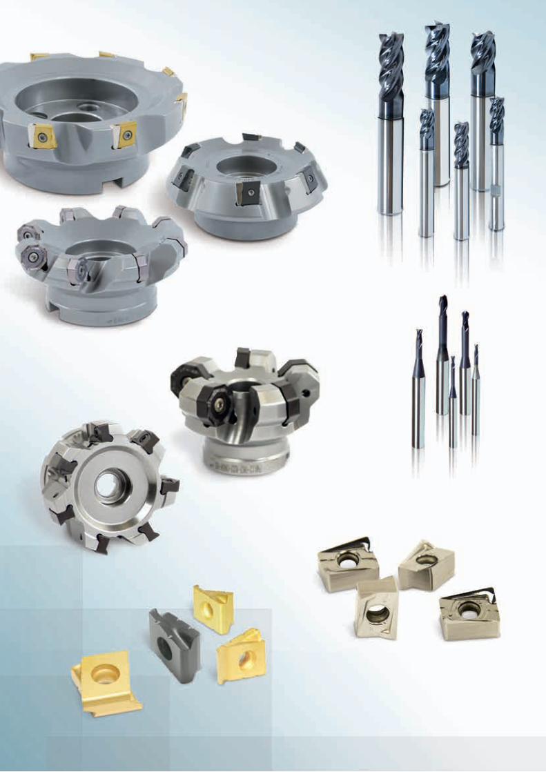
ZCC-CT, one of the World’s leading carbide tooling manufacturers, welcomes you to its products. We are able to offer you a wide product range of high performance cutting tools at economic prices and a good supply service to support the production and productivity at your manufacturing facilities. You will find the main tool types in the various sections of the catalogue, Turning is in section A, Milling in section B and Drilling in section C of the catalogue.
We are looking forward to working with you and developing good cooperation together.Our team at ZCC Cutting Tools Europe is ready to support you in all of your requirements.
HAUPTSITZ IN EUROPA:ZCC Cutting Tools Europe GmbH, Wanheimer Str.57, 40472 Düsseldorf, GermanyTel.: +49 (0) 211/989240-0, Fax: +49 (0) 211/ 989240-111E-Mail: [email protected], www.zccct-europe.com, www.zccct.com
Member of Minmetals Group
Copyright Katalog©2016 ZCC Cutting Tools Europe GmbH
All rights reserved. All descriptions and pictures are protected by copyright. Usage, modification and reproduction, completely or partially, without written permission are prohibited. Subject to technical changes and changes of the delivery program. Mistakes and printing errors are reserved.
A
B
C
D
E
Turning General turning A1-A336
Parting & grooving A337-A402
Threading A403-A455
Milling Indexable milling B1-B248
Solid carbide milling B249-B462
Drilling Indexable drills C1-C24
Solid carbide drills C25-C126
Solid carbide reamers C127-C140
Solid carbide threading tools C141-C182
Technical information D1-D24
Index E1-E8
B 2
B 249
A
B
C
D
E
Turn
ing
Mill
ing
Dril
ling
Inde
xTe
chni
cal
Info
rmat
ion
Solid carbide milling
Product overview B250-B256
Grade overview B257
System code – DIN-ISO series B258
System code – JIS series B259-B260
GM series B261-B318
PM series B319-B342
HM series B343-B366
NM series B367-B374
AL series B375-B392
HPC series B393-B400
UM series B401-B410
VSM series B411-B416
Deburring cutters – FM series B417-B421
Recommended cutting data B422-B446
Technical information B457-B460
Form nonstandard order B461-B462
B
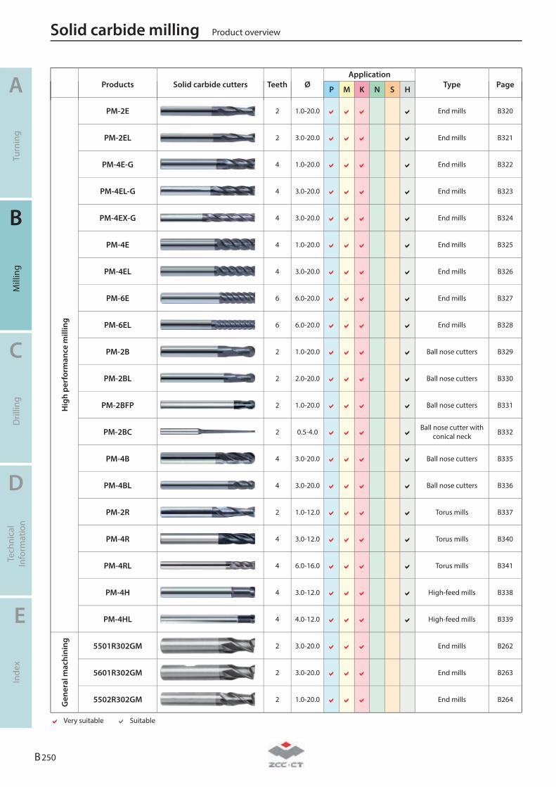
Products Solid carbide cutters Teeth Ø
Application Type Page P M K N S H
Hig
h pe
rfor
man
ce m
illin
g
PM-2E 2 1.0-20.0
End mills B320
PM-2EL 2 3.0-20.0
End mills B321
PM-4E-G 4 1.0-20.0
End mills B322
PM-4EL-G 4 3.0-20.0
End mills B323
PM-4EX-G 4 3.0-20.0
End mills B324
PM-4E 4 1.0-20.0
End mills B325
PM-4EL 4 3.0-20.0
End mills B326
PM-6E 6 6.0-20.0
End mills B327
PM-6EL 6 6.0-20.0
End mills B328
PM-2B 2 1.0-20.0
Ball nose cutters B329
PM-2BL 2 2.0-20.0
Ball nose cutters B330
PM-2BFP 2 1.0-20.0
Ball nose cutters B331
PM-2BC 2 0.5-4.0
Ball nose cutter with
conical neck B332
PM-4B 4 3.0-20.0
Ball nose cutters B335
PM-4BL 4 3.0-20.0
Ball nose cutters B336
PM-2R 2 1.0-12.0
Torus mills B337
PM-4R 4 3.0-12.0
Torus mills B340
PM-4RL 4 6.0-16.0
Torus mills B341
PM-4H 4 3.0-12.0
High-feed mills B338
PM-4HL 4 4.0-12.0
High-feed mills B339
Gen
eral
mac
hini
ng
5501R302GM 2 3.0-20.0
End mills B262
5601R302GM 2 3.0-20.0
End mills B263
5502R302GM 2 1.0-20.0
End mills B264
Very suitable Suitable
Solid carbide milling Product overview
A
Turn
ing
B
Mill
ing
C
Dril
ling
D
Tech
nica
l In
form
atio
n
E
Inde
x
B 250
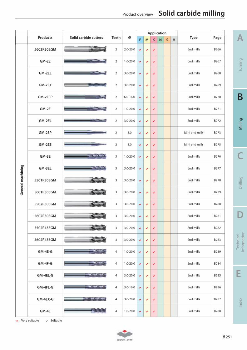
Products Solid carbide cutters Teeth Ø
Application Type Page P M K N S H
Gen
eral
mac
hini
ng
5602R302GM 2 2.0-20.0
End mills B266
GM-2E 2 1.0-20.0
End mills B267
GM-2EL 2 3.0-20.0
End mills B268
GM-2EX 2 3.0-20.0
End mills B269
GM-2EFP 2 6.0-16.0
End mills B270
GM-2F 2 1.0-20.0
End mills B271
GM-2FL 2 3.0-20.0
End mills B272
GM-2EP 2 5.0
Mini end mills B273
GM-2ES 2 3.0
Mini end mills B275
GM-3E 3 1.0-20.0
End mills B276
GM-3EL 3 3.0-20.0
End mills B277
5501R303GM 3 3.0-20.0
End mills B278
5601R303GM 3 3.0-20.0
End mills B279
5502R303GM 3 3.0-20.0
End mills B280
5602R303GM 3 3.0-20.0
End mills B281
5502R453GM 3 3.0-20.0
End mills B282
5602R453GM 3 3.0-20.0
End mills B283
GM-4E-G 4 1.0-20.0
End mills B289
GM-4F-G 4 1.0-20.0
End mills B284
GM-4EL-G 4 3.0-20.0
End mills B285
GM-4FL-G 4 3.0-16.0
End mills B286
GM-4EX-G 4 3.0-20.0
End mills B287
GM-4E 4 1.0-20.0
End mills B288
Very suitable Suitable
Product overview Solid carbide milling
A
Turn
ing
B
Mill
ing
C
Dril
ling
D
Tech
nica
l In
form
atio
n
E
Inde
x
B 251
Products Solid carbide cutters Teeth Ø
Application Type Page P M K N S H
Gen
eral
mac
hini
ng
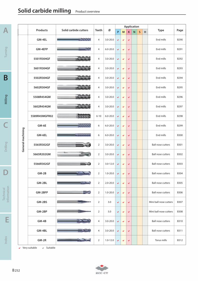
GM-4EL 4 3.0-20.0
End mills B290
GM-4EFP 4 6.0-20.0
End mills B291
5501R304GF 4 3.0-20.0
End mills B292
5601R304GF 4 3.0-20.0
End mills B293
5502R304GF 4 3.0-20.0
End mills B294
5602R304GF 4 3.0-20.0
End mills B295
5508R454GM 4 3.0-20.0
End mills B296
5602R454GM 4 3.0-20.0
End mills B297
5589R45MGFR02 6-10 6.0-20.0
End mills B298
GM-6E 6 6.0-20.0
End mills B299
GM-6EL 6 6.0-20.0
End mills B300
5565R302GF 2 3.0-20.0
Ball nose cutters B301
5665R202GM 2 3.0-20.0
Ball nose cutters B302
5566R302GF 2 3.0-12.0
Ball nose cutters B303
GM-2B 2 1.0-20.0
Ball nose cutters B304
GM-2BL 2 2.0-20.0
Ball nose cutters B305
GM-2BFP 2 1.0-20.0
Ball nose cutters B306
GM-2BS 2 3.0
Mini ball nose cutters B307
GM-2BP 2 5.0
Mini ball nose cutters B308
GM-4B 4 3.0-20.0
Ball nose cutters B310
GM-4BL 4 3.0-20.0
Ball nose cutters B311
GM-2R 2 1.0-12.0
Torus mills B312
Very suitable Suitable
Solid carbide milling Product overview
A
Turn
ing
B
Mill
ing
C
Dril
ling
D
Tech
nica
l In
form
atio
n
E
Inde
x
B 252
Products Solid carbide cutters Teeth Ø
Application Type Page P M K N S H
Gen
eral
mac
hini
ng
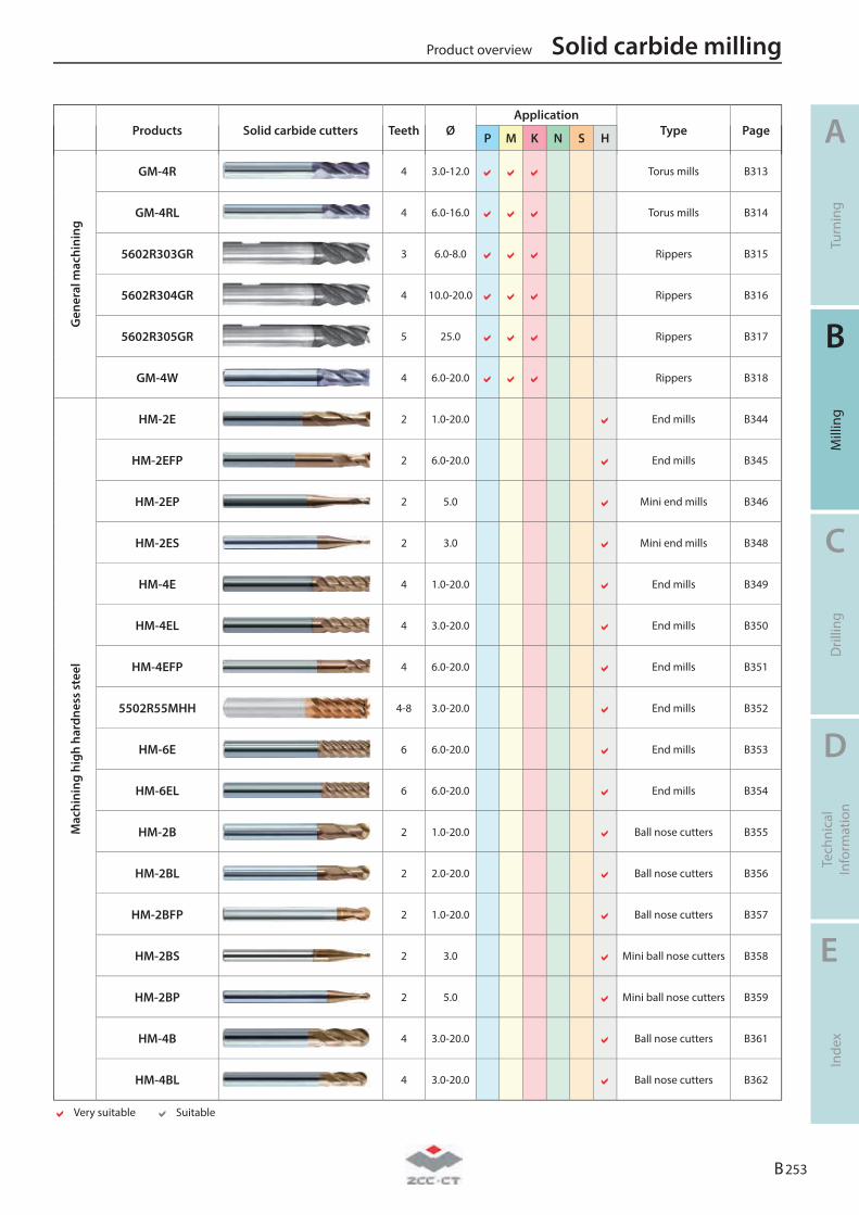
GM-4R 4 3.0-12.0
Torus mills B313
GM-4RL 4 6.0-16.0
Torus mills B314
5602R303GR 3 6.0-8.0
Rippers B315
5602R304GR 4 10.0-20.0
Rippers B316
5602R305GR 5 25.0
Rippers B317
GM-4W 4 6.0-20.0
Rippers B318
Mac
hini
ng h
igh
hard
ness
ste
el
HM-2E 2 1.0-20.0
End mills B344
HM-2EFP 2 6.0-20.0
End mills B345
HM-2EP 2 5.0
Mini end mills B346
HM-2ES 2 3.0
Mini end mills B348
HM-4E 4 1.0-20.0
End mills B349
HM-4EL 4 3.0-20.0
End mills B350
HM-4EFP 4 6.0-20.0
End mills B351
5502R55MHH 4-8 3.0-20.0
End mills B352
HM-6E 6 6.0-20.0
End mills B353
HM-6EL 6 6.0-20.0
End mills B354
HM-2B 2 1.0-20.0
Ball nose cutters B355
HM-2BL 2 2.0-20.0
Ball nose cutters B356
HM-2BFP 2 1.0-20.0
Ball nose cutters B357
HM-2BS 2 3.0
Mini ball nose cutters B358
HM-2BP 2 5.0
Mini ball nose cutters B359
HM-4B 4 3.0-20.0
Ball nose cutters B361
HM-4BL 4 3.0-20.0
Ball nose cutters B362
Very suitable Suitable
Product overview Solid carbide milling
A
Turn
ing
B
Mill
ing
C
Dril
ling
D
Tech
nica
l In
form
atio
n
E
Inde
x
B 253
Products Solid carbide cutters Teeth Ø
Application Type Page P M K N S H
Mac
hini
ng h
igh
hard
-ne
ss s
teel
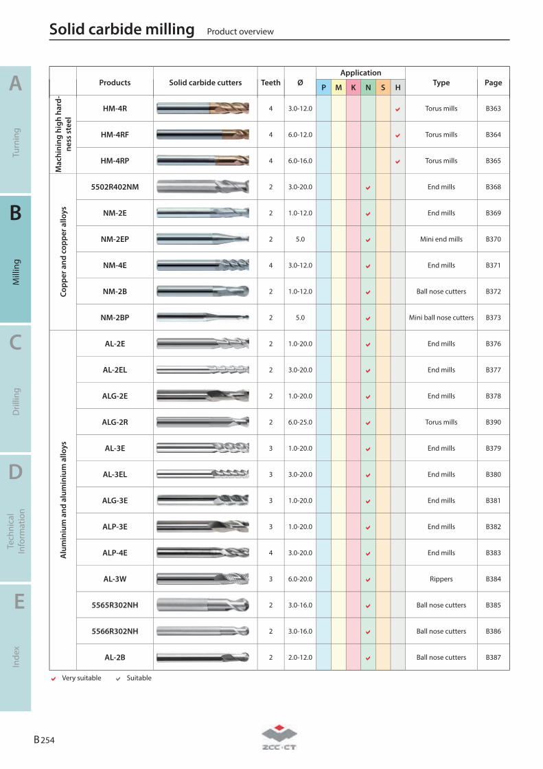
HM-4R 4 3.0-12.0
Torus mills B363
HM-4RF 4 6.0-12.0
Torus mills B364
HM-4RP 4 6.0-16.0
Torus mills B365
Copp
er a
nd c
oppe
r allo
ys
5502R402NM 2 3.0-20.0
End mills B368
NM-2E 2 1.0-12.0
End mills B369
NM-2EP 2 5.0
Mini end mills B370
NM-4E 4 3.0-12.0
End mills B371
NM-2B 2 1.0-12.0
Ball nose cutters B372
NM-2BP 2 5.0
Mini ball nose cutters B373
Alu
min
ium
and
alu
min
ium
allo
ys
AL-2E 2 1.0-20.0
End mills B376
AL-2EL 2 3.0-20.0
End mills B377
ALG-2E 2 1.0-20.0
End mills B378
ALG-2R 2 6.0-25.0
Torus mills B390
AL-3E 3 1.0-20.0
End mills B379
AL-3EL 3 3.0-20.0
End mills B380
ALG-3E 3 1.0-20.0
End mills B381
ALP-3E 3 1.0-20.0
End mills B382
ALP-4E 4 3.0-20.0
End mills B383
AL-3W 3 6.0-20.0
Rippers B384
5565R302NH 2 3.0-16.0
Ball nose cutters B385
5566R302NH 2 3.0-16.0
Ball nose cutters B386
AL-2B 2 2.0-12.0
Ball nose cutters B387
Very suitable Suitable
Solid carbide milling Product overview
A
Turn
ing
B
Mill
ing
C
Dril
ling
D
Tech
nica
l In
form
atio
n
E
Inde
x
B 254
Products Solid carbide cutters Teeth Ø
Application Type Page P M K N S H
Alu
min
ium
and
alu
min
ium
al
loys
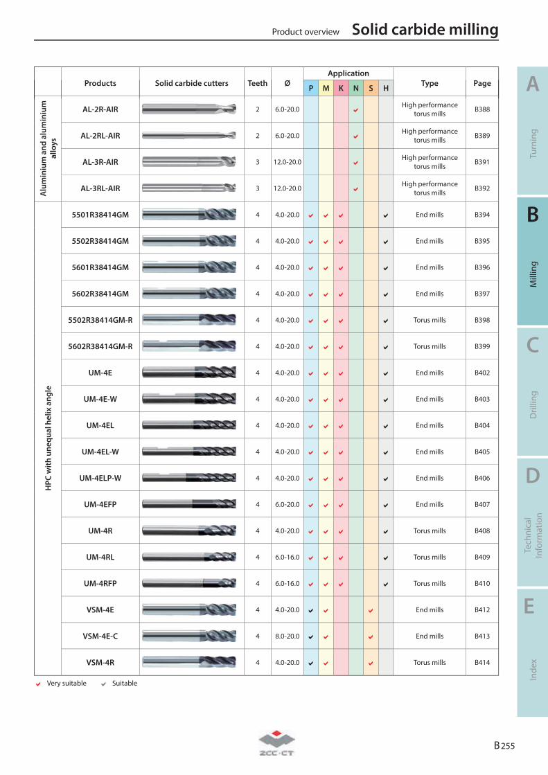
AL-2R-AIR 2 6.0-20.0
High performance
torus mills B388
AL-2RL-AIR 2 6.0-20.0
High performance
torus mills B389
AL-3R-AIR 3 12.0-20.0
High performance
torus mills B391
AL-3RL-AIR 3 12.0-20.0
High performance
torus mills B392
HPC
with
une
qual
hel
ix a
ngle
5501R38414GM 4 4.0-20.0
End mills B394
5502R38414GM 4 4.0-20.0
End mills B395
5601R38414GM 4 4.0-20.0
End mills B396
5602R38414GM 4 4.0-20.0
End mills B397
5502R38414GM-R 4 4.0-20.0
Torus mills B398
5602R38414GM-R 4 4.0-20.0
Torus mills B399
UM-4E 4 4.0-20.0
End mills B402
UM-4E-W 4 4.0-20.0
End mills B403
UM-4EL 4 4.0-20.0
End mills B404
UM-4EL-W 4 4.0-20.0
End mills B405
UM-4ELP-W 4 4.0-20.0
End mills B406
UM-4EFP 4 6.0-20.0
End mills B407
UM-4R 4 4.0-20.0
Torus mills B408
UM-4RL 4 6.0-16.0
Torus mills B409
UM-4RFP 4 6.0-16.0
Torus mills B410
VSM-4E 4 4.0-20.0
End mills B412
VSM-4E-C 4 8.0-20.0
End mills B413
VSM-4R 4 4.0-20.0
Torus mills B414
Very suitable Suitable
Product overview Solid carbide milling
A
Turn
ing
B
Mill
ing
C
Dril
ling
D
Tech
nica
l In
form
atio
n
E
Inde
x
B 255
Products Solid carbide cutters Teeth Ø
Application Type Page P M K N S H
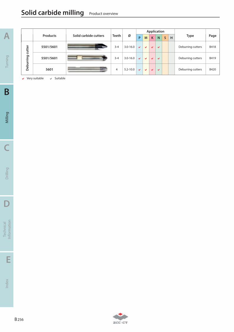
Deb
urri
ng c
utte
r 5501/5601 3-4 3.0-16.0
Deburring cutters B418
5501/5601 3-4 3.0-16.0
Deburring cutters B419
5601 4 5.2-10.0
Deburring cutters B420
Very suitable Suitable
Solid carbide milling Product overview
A
Turn
ing
B
Mill
ing
C
Dril
ling
D
Tech
nica
l In
form
atio
n
E
Inde
x
B 256
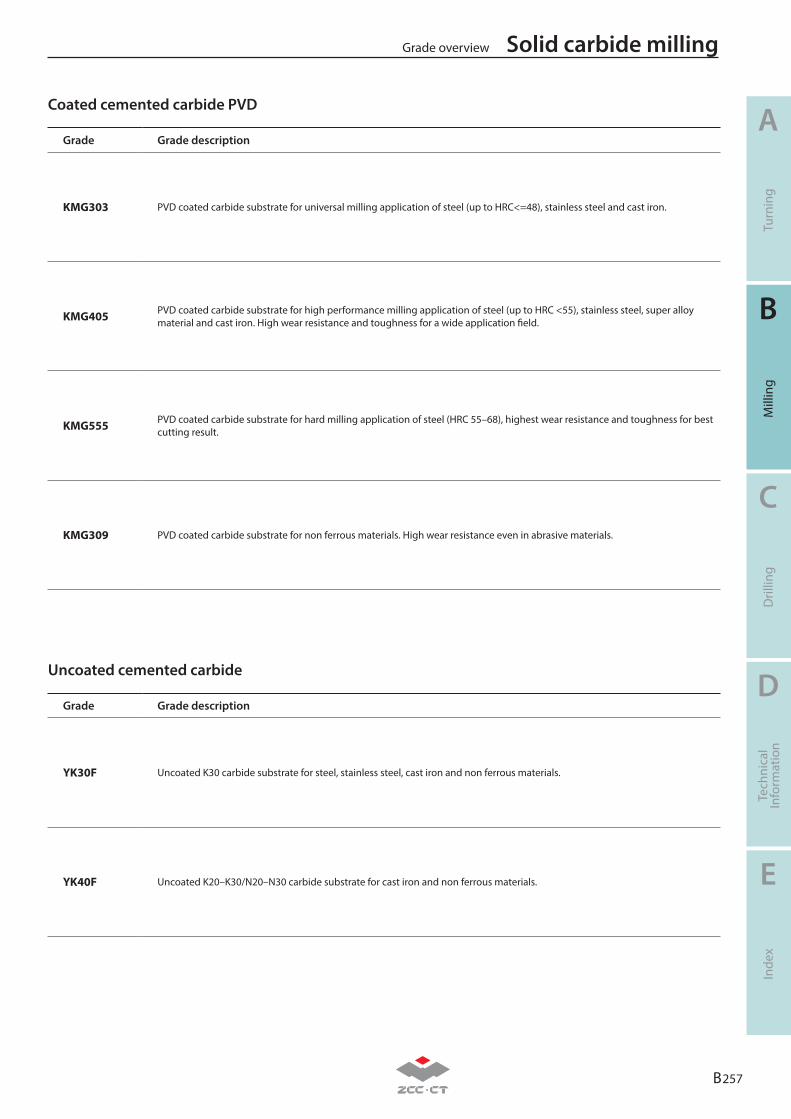
Coated cemented carbide PVD
Uncoated cemented carbide
B 257
A
B
C
D
E
Turn
ing
Mill
ing
Dril
ling
Tech
nica
lIn
form
atio
nIn
dex
Solid carbide millingGrade overview
Grade Grade description
KMG303 PVD coated carbide substrate for universal milling application of steel (up to HRC<=48), stainless steel and cast iron.
KMG405 PVD coated carbide substrate for high performance milling application of steel (up to HRC <55), stainless steel, super alloy material and cast iron. High wear resistance and toughness for a wide application field.
KMG555 PVD coated carbide substrate for hard milling application of steel (HRC 55–68), highest wear resistance and toughness for best cutting result.
KMG309 PVD coated carbide substrate for non ferrous materials. High wear resistance even in abrasive materials.
Grade Grade description
YK30F Uncoated K30 carbide substrate for steel, stainless steel, cast iron and non ferrous materials.
YK40F Uncoated K20–K30/N20–N30 carbide substrate for cast iron and non ferrous materials.
B 258
A
B
C
D
E
Turn
ing
Mill
ing
Dril
ling
Tech
nica
lIn
form
atio
nIn
dex
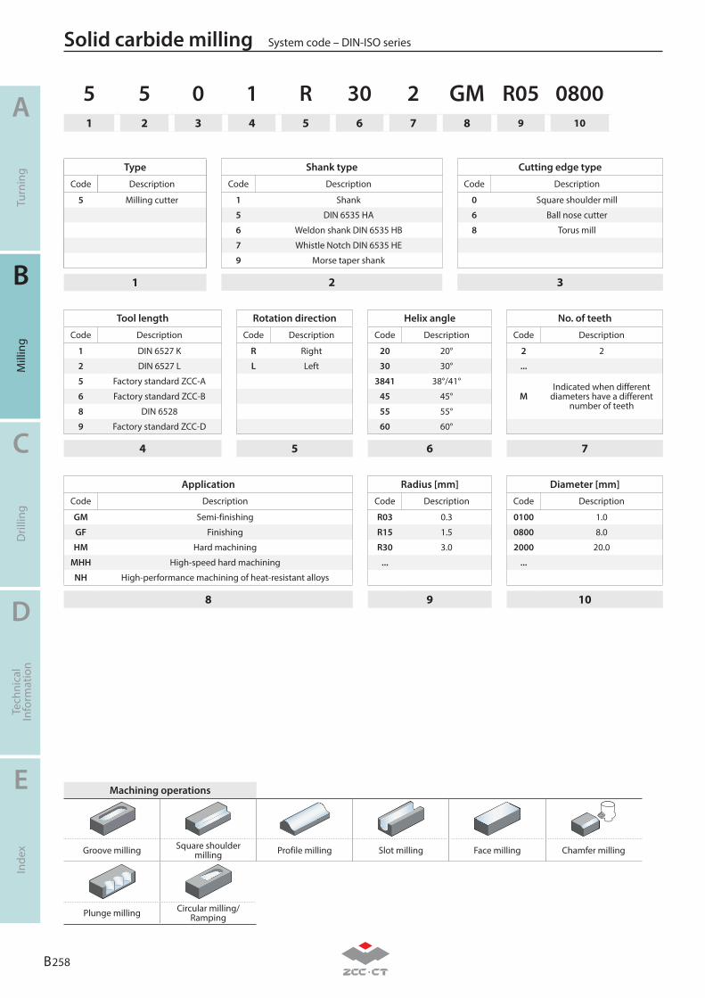
Solid carbide milling System code – DIN-ISO series
5 5 0 1 R 30 2 GM R05 08001 2 3 4 5 6 7 8 9 10
Type
Code Description
5 Milling cutter
1
Tool length
Code Description
1 DIN 6527 K
2 DIN 6527 L
5 Factory standard ZCC-A
6 Factory standard ZCC-B
8 DIN 6528
9 Factory standard ZCC-D
4
Rotation direction
Code Description
R Right
L Left
5
Helix angle
Code Description
20 20°
30 30°
3841 38°/41°
45 45°
55 55°
60 60°
6
Radius [mm]
Code Description
R03 0.3
R15 1.5
R30 3.0
...
9
No. of teeth
Code Description
2 2
...
MIndicated when different
diameters have a different number of teeth
7
Diameter [mm]
Code Description
0100 1.0
0800 8.0
2000 20.0
...
10
Shank type
Code Description
1 Shank
5 DIN 6535 HA
6 Weldon shank DIN 6535 HB
7 Whistle Notch DIN 6535 HE
9 Morse taper shank
2
Cutting edge type
Code Description
0 Square shoulder mill
6 Ball nose cutter
8 Torus mill
3
Application
Code Description
GM Semi-finishing
GF Finishing
HM Hard machining
MHH High-speed hard machining
NH High-performance machining of heat-resistant alloys
8
Machining operations
Groove milling Square shoulder milling Profile milling Slot milling Face milling Chamfer milling
Plunge milling Circular milling/ Ramping
B 259
A
B
C
D
E
Turn
ing
Mill
ing
Dril
ling
Tech
nica
lIn
form
atio
nIn
dex
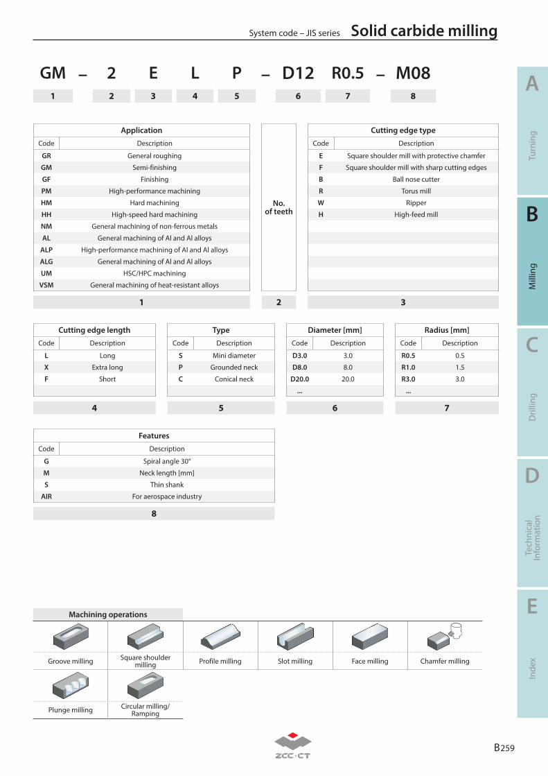
Solid carbide millingSystem code – JIS series
GM – 2 E L P – D12 R0.5 – M081 2 3 4 5 6 7 8
Cutting edge length
Code Description
L Long
X Extra long
F Short
4
Type
Code Description
S Mini diameter
P Grounded neck
C Conical neck
5
Features
Code Description
G Spiral angle 30°
M Neck length [mm]
S Thin shank
AIR For aerospace industry
8
Cutting edge type
Code Description
E Square shoulder mill with protective chamfer
F Square shoulder mill with sharp cutting edges
B Ball nose cutter
R Torus mill
W Ripper
H High-feed mill
3
No. of teeth
2
Radius [mm]
Code Description
R0.5 0.5
R1.0 1.5
R3.0 3.0
...
7
Diameter [mm]
Code Description
D3.0 3.0
D8.0 8.0
D20.0 20.0
...
6
Application
Code Description
GR General roughing
GM Semi-finishing
GF Finishing
PM High-performance machining
HM Hard machining
HH High-speed hard machining
NM General machining of non-ferrous metals
AL General machining of Al and Al alloys
ALP High-performance machining of Al and Al alloys
ALG General machining of Al and Al alloys
UM HSC/HPC machining
VSM General machining of heat-resistant alloys
1
Machining operations
Groove milling Square shoulder milling Profile milling Slot milling Face milling Chamfer milling
Plunge milling Circular milling/ Ramping

B 260
A
B
C
D
E
Turn
ing
Mill
ing
Dril
ling
Tech
nica
lIn
form
atio
nIn
dex
Solid carbide milling System code – JIS series
Notes
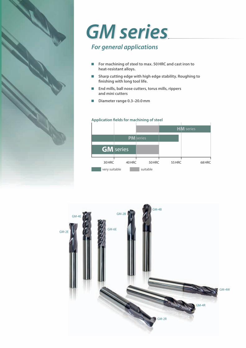
For machining of steel to max. 50 HRC and cast iron to heat-resistant alloys.
Sharp cutting edge with high edge stability. Roughing to fi nishing with long tool life.
End mills, ball nose cutters, torus mills, rippers and mini cutters
Diameter range 0.3–20.0 mm
GM seriesFor general applications
Application fi elds for machining of steel
30 HRC 40 HRC 50 HRC 55 HRC 68 HRC
very suitable suitable
HM series
PM series
GM series
GM-4E
GM-4B
GM-4W
GM-4R
GM-2R
GM-6EGM-2E
GM-2B
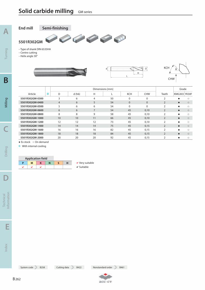
End mill Semi-finishing
5501R302GM
– Type of shank DIN 6535HA – Centre cutting – Helix angle 30°
LH
Dd
KCH
CHW
Dimensions [mm] Grade
Article D d (h6) H L KCH CHW Teeth KMG303 YK30F
5501R302GM-0300 3 6 4 50 0 0 2 ● ○ 5501R302GM-0400 4 6 5 54 0 0 2 ● ○ 5501R302GM-0500 5 6 6 54 0 0 2 ● ○ 5501R302GM-0600 6 6 7 54 45 0,10 2 ● ○ 5501R302GM-0800 8 8 9 58 45 0,10 2 ● ○ 5501R302GM-1000 10 10 11 66 45 0,10 2 ● ○ 5501R302GM-1200 12 12 12 73 45 0,10 2 ● ○ 5501R302GM-1400 14 14 14 75 45 0,15 2 ● ○ 5501R302GM-1600 16 16 16 82 45 0,15 2 ● ○ 5501R302GM-1800 18 18 18 84 45 0,15 2 ● ○ 5501R302GM-2000 20 20 20 92 45 0,15 2 ● ○
● Ex stock ○ On demand With internal cooling
Application field P M K N S H
Very suitable Suitable
Solid carbide milling GM series
A
Turn
ing
B
Mill
ing
C
Dril
ling
D
Tech
nica
l In
form
atio
n
E
Inde
x
B 262
System code B258 Cutting data B422 Nonstandard order B461
System code B258 Cutting data B422 Nonstandard order B461
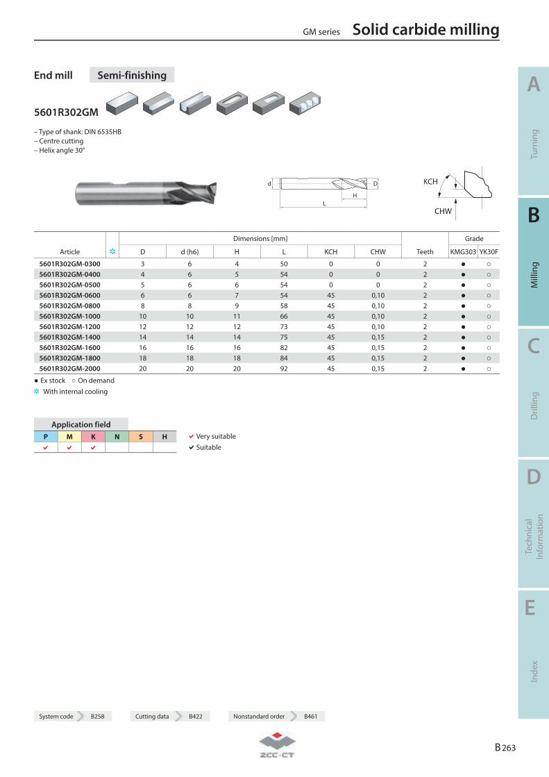
End mill Semi-finishing
5601R302GM
– Type of shank: DIN 6535HB – Centre cutting – Helix angle 30°
LH
Dd
KCH
CHW
Dimensions [mm] Grade
Article D d (h6) H L KCH CHW Teeth KMG303 YK30F
5601R302GM-0300 3 6 4 50 0 0 2 ● ○ 5601R302GM-0400 4 6 5 54 0 0 2 ● ○ 5601R302GM-0500 5 6 6 54 0 0 2 ● ○ 5601R302GM-0600 6 6 7 54 45 0,10 2 ● ○ 5601R302GM-0800 8 8 9 58 45 0,10 2 ● ○ 5601R302GM-1000 10 10 11 66 45 0,10 2 ● ○ 5601R302GM-1200 12 12 12 73 45 0,10 2 ● ○ 5601R302GM-1400 14 14 14 75 45 0,15 2 ● ○ 5601R302GM-1600 16 16 16 82 45 0,15 2 ● ○ 5601R302GM-1800 18 18 18 84 45 0,15 2 ● ○ 5601R302GM-2000 20 20 20 92 45 0,15 2 ● ○
● Ex stock ○ On demand With internal cooling
Application field P M K N S H
Very suitable Suitable
GM series Solid carbide milling
A
Turn
ing
B
Mill
ing
C
Dril
ling
D
Tech
nica
l In
form
atio
n
E
Inde
x
B 263
System code B258 Cutting data B422 Nonstandard order B461
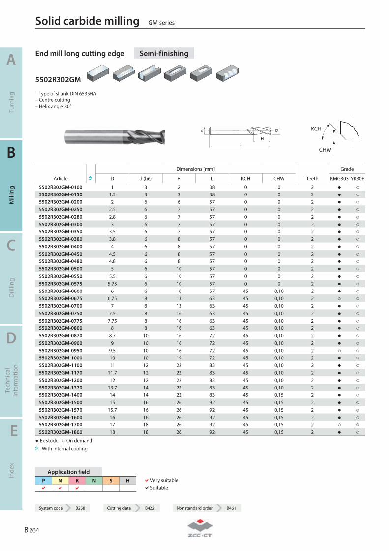
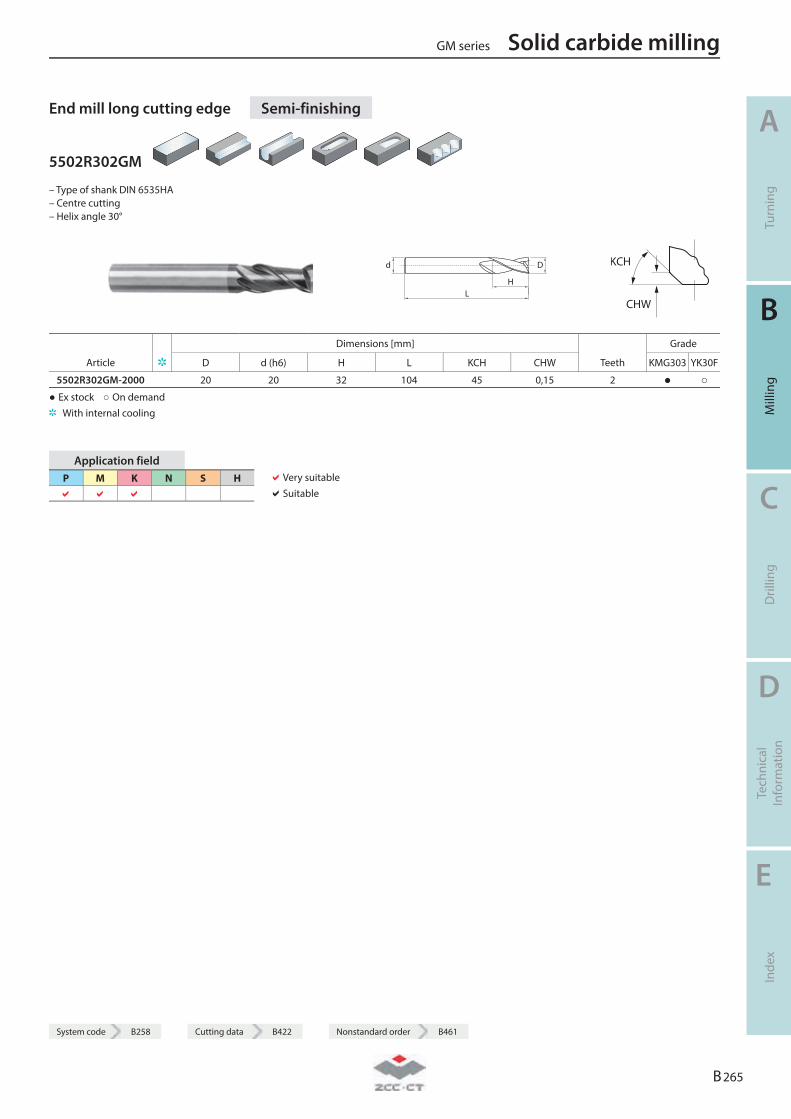
End mill long cutting edge Semi-finishing
5502R302GM
– Type of shank DIN 6535HA – Centre cutting – Helix angle 30°
LH
Dd
KCH
CHW
Dimensions [mm] Grade
Article D d (h6) H L KCH CHW Teeth KMG303 YK30F
5502R302GM-0100 1 3 2 38 0 0 2 ● ○ 5502R302GM-0150 1.5 3 3 38 0 0 2 ● ○ 5502R302GM-0200 2 6 6 57 0 0 2 ● ○ 5502R302GM-0250 2.5 6 7 57 0 0 2 ● ○ 5502R302GM-0280 2.8 6 7 57 0 0 2 ● ○ 5502R302GM-0300 3 6 7 57 0 0 2 ● ○ 5502R302GM-0350 3.5 6 7 57 0 0 2 ● ○ 5502R302GM-0380 3.8 6 8 57 0 0 2 ● ○ 5502R302GM-0400 4 6 8 57 0 0 2 ● ○ 5502R302GM-0450 4.5 6 8 57 0 0 2 ● ○ 5502R302GM-0480 4.8 6 8 57 0 0 2 ● ○ 5502R302GM-0500 5 6 10 57 0 0 2 ● ○ 5502R302GM-0550 5.5 6 10 57 0 0 2 ● ○ 5502R302GM-0575 5.75 6 10 57 0 0 2 ● ○ 5502R302GM-0600 6 6 10 57 45 0,10 2 ● ○ 5502R302GM-0675 6.75 8 13 63 45 0,10 2 ○ ○ 5502R302GM-0700 7 8 13 63 45 0,10 2 ● ○ 5502R302GM-0750 7.5 8 16 63 45 0,10 2 ● ○ 5502R302GM-0775 7.75 8 16 63 45 0,10 2 ● ○ 5502R302GM-0800 8 8 16 63 45 0,10 2 ● ○ 5502R302GM-0870 8.7 10 16 72 45 0,10 2 ● ○ 5502R302GM-0900 9 10 16 72 45 0,10 2 ● ○ 5502R302GM-0950 9.5 10 16 72 45 0,10 2 ○ ○ 5502R302GM-1000 10 10 19 72 45 0,10 2 ● ○ 5502R302GM-1100 11 12 22 83 45 0,10 2 ● ○ 5502R302GM-1170 11.7 12 22 83 45 0,10 2 ● ○ 5502R302GM-1200 12 12 22 83 45 0,10 2 ● ○ 5502R302GM-1370 13.7 14 22 83 45 0,10 2 ● ○ 5502R302GM-1400 14 14 22 83 45 0,15 2 ● ○ 5502R302GM-1500 15 16 26 92 45 0,15 2 ● ○ 5502R302GM-1570 15.7 16 26 92 45 0,15 2 ● ○ 5502R302GM-1600 16 16 26 92 45 0,15 2 ● ○ 5502R302GM-1700 17 18 26 92 45 0,15 2 ○ ○ 5502R302GM-1800 18 18 26 92 45 0,15 2 ● ○
● Ex stock ○ On demand With internal cooling
Application field P M K N S H
Very suitable Suitable
Solid carbide milling GM series
A
Turn
ing
B
Mill
ing
C
Dril
ling
D
Tech
nica
l In
form
atio
n
E
Inde
x
B 264
System code B258 Cutting data B422 Nonstandard order B461
System code B258 Cutting data B422 Nonstandard order B461
End mill long cutting edge Semi-finishing
5502R302GM
– Type of shank DIN 6535HA – Centre cutting – Helix angle 30°
LH
Dd
KCH
CHW
Dimensions [mm] Grade
Article D d (h6) H L KCH CHW Teeth KMG303 YK30F
5502R302GM-2000 20 20 32 104 45 0,15 2 ● ○ ● Ex stock ○ On demand With internal cooling
Application field P M K N S H
Very suitable Suitable
GM series Solid carbide milling
A
Turn
ing
B
Mill
ing
C
Dril
ling
D
Tech
nica
l In
form
atio
n
E
Inde
x
B 265
System code B258 Cutting data B422 Nonstandard order B461
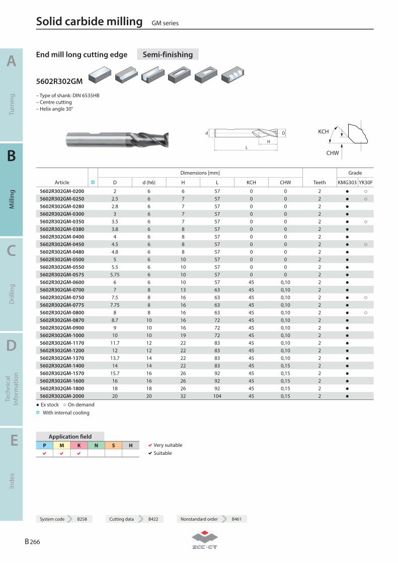
End mill long cutting edge Semi-finishing
5602R302GM
– Type of shank: DIN 6535HB – Centre cutting – Helix angle 30°
LH
Dd
KCH
CHW
Dimensions [mm] Grade
Article D d (h6) H L KCH CHW Teeth KMG303 YK30F
5602R302GM-0200 2 6 6 57 0 0 2 ● ○ 5602R302GM-0250 2.5 6 7 57 0 0 2 ● ○ 5602R302GM-0280 2.8 6 7 57 0 0 2 ● 5602R302GM-0300 3 6 7 57 0 0 2 ● 5602R302GM-0350 3.5 6 7 57 0 0 2 ● ○ 5602R302GM-0380 3.8 6 8 57 0 0 2 ● 5602R302GM-0400 4 6 8 57 0 0 2 ● 5602R302GM-0450 4.5 6 8 57 0 0 2 ● ○ 5602R302GM-0480 4.8 6 8 57 0 0 2 ● 5602R302GM-0500 5 6 10 57 0 0 2 ● 5602R302GM-0550 5.5 6 10 57 0 0 2 ● 5602R302GM-0575 5.75 6 10 57 0 0 2 ● 5602R302GM-0600 6 6 10 57 45 0,10 2 ● 5602R302GM-0700 7 8 13 63 45 0,10 2 ● 5602R302GM-0750 7.5 8 16 63 45 0,10 2 ● ○ 5602R302GM-0775 7.75 8 16 63 45 0,10 2 ● 5602R302GM-0800 8 8 16 63 45 0,10 2 ● ○ 5602R302GM-0870 8.7 10 16 72 45 0,10 2 ● 5602R302GM-0900 9 10 16 72 45 0,10 2 ● 5602R302GM-1000 10 10 19 72 45 0,10 2 ● 5602R302GM-1170 11.7 12 22 83 45 0,10 2 ● 5602R302GM-1200 12 12 22 83 45 0,10 2 ● 5602R302GM-1370 13.7 14 22 83 45 0,10 2 ● 5602R302GM-1400 14 14 22 83 45 0,15 2 ● 5602R302GM-1570 15.7 16 26 92 45 0,15 2 ● 5602R302GM-1600 16 16 26 92 45 0,15 2 ● 5602R302GM-1800 18 18 26 92 45 0,15 2 ● 5602R302GM-2000 20 20 32 104 45 0,15 2 ●
● Ex stock ○ On demand With internal cooling
Application field P M K N S H
Very suitable Suitable
Solid carbide milling GM series
A
Turn
ing
B
Mill
ing
C
Dril
ling
D
Tech
nica
l In
form
atio
n
E
Inde
x
B 266
System code B258 Cutting data B422 Nonstandard order B461

System code B258 Cutting data B422 Nonstandard order B461
End mill Semi-finishing
GM-2E
– Factory standard – Centre cutting – Helix angle 35°
L
d
H
D
10° A
L
D
H
d
B
Dimensions [mm] Grade
Article D d (h6) H L Teeth Geometry KMG303
GM-2E-D1.0S 1 4 3 50 2 A ● GM-2E-D1.5S 1.5 4 4 50 2 A ● GM-2E-D2.0S 2 4 6 50 2 A ● GM-2E-D2.5S 2.5 4 8 50 2 A ● GM-2E-D3.0S 3 4 8 50 2 A ● GM-2E-D4.0S 4 4 11 50 2 B ● GM-2E-D1.0 1 6 3 50 2 A ● GM-2E-D1.5 1.5 6 4 50 2 A ● GM-2E-D2.0 2 6 6 50 2 A ● GM-2E-D2.5 2.5 6 8 50 2 A ● GM-2E-D3.0 3 6 8 50 2 A ● GM-2E-D3.5 3.5 6 10 50 2 A ● GM-2E-D4.0 4 6 11 50 2 A ● GM-2E-D4.5 4.5 6 11 50 2 A ● GM-2E-D5.0 5 6 13 50 2 A ● GM-2E-D5.5 5.5 6 16 50 2 A ● GM-2E-D6.0 6 6 16 50 2 B ● GM-2E-D7.0 7 8 20 60 2 A ● GM-2E-D8.0 8 8 20 60 2 B ● GM-2E-D9.0 9 10 22 75 2 A ● GM-2E-D10.0 10 10 25 75 2 B ● GM-2E-D11.0 11 12 26 75 2 A ● GM-2E-D12.0 12 12 30 75 2 B ● GM-2E-D14.0 14 14 32 75 2 B ● GM-2E-D16.0 16 16 45 100 2 B ● GM-2E-D18.0 18 18 45 100 2 B ● GM-2E-D20.0 20 20 45 100 2 B ●
● Ex stock ○ On demand With internal cooling
Application field P M K N S H
Very suitable Suitable
GM series Solid carbide milling
A
Turn
ing
B
Mill
ing
C
Dril
ling
D
Tech
nica
l In
form
atio
n
E
Inde
x
B 267
System code B258 Cutting data B422 Nonstandard order B461
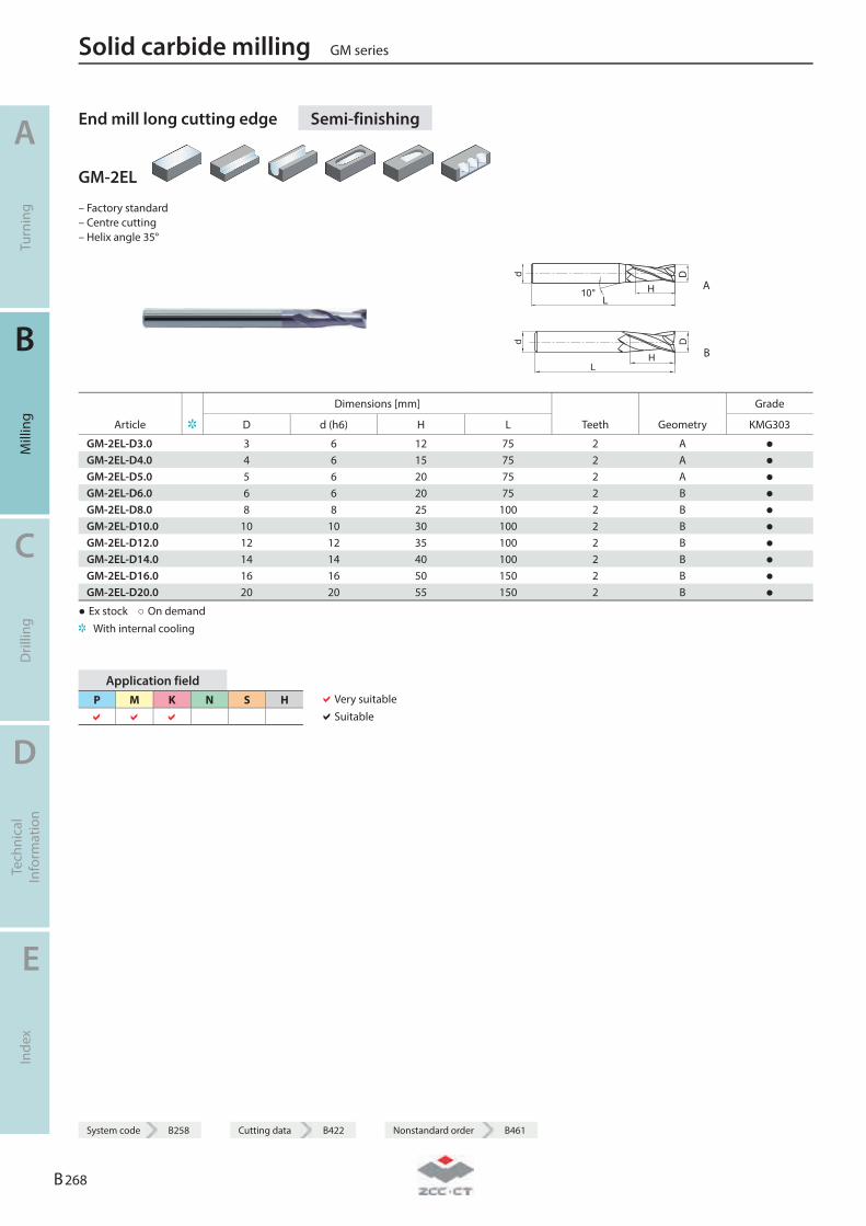
End mill long cutting edge Semi-finishing
GM-2EL
– Factory standard – Centre cutting – Helix angle 35°
L
d
H
D
10° A
L
Dd
H B
Dimensions [mm] Grade
Article D d (h6) H L Teeth Geometry KMG303
GM-2EL-D3.0 3 6 12 75 2 A ● GM-2EL-D4.0 4 6 15 75 2 A ● GM-2EL-D5.0 5 6 20 75 2 A ● GM-2EL-D6.0 6 6 20 75 2 B ● GM-2EL-D8.0 8 8 25 100 2 B ● GM-2EL-D10.0 10 10 30 100 2 B ● GM-2EL-D12.0 12 12 35 100 2 B ● GM-2EL-D14.0 14 14 40 100 2 B ● GM-2EL-D16.0 16 16 50 150 2 B ● GM-2EL-D20.0 20 20 55 150 2 B ●
● Ex stock ○ On demand With internal cooling
Application field P M K N S H
Very suitable Suitable
Solid carbide milling GM series
A
Turn
ing
B
Mill
ing
C
Dril
ling
D
Tech
nica
l In
form
atio
n
E
Inde
x
B 268
System code B258 Cutting data B422 Nonstandard order B461
System code B258 Cutting data B422 Nonstandard order B461
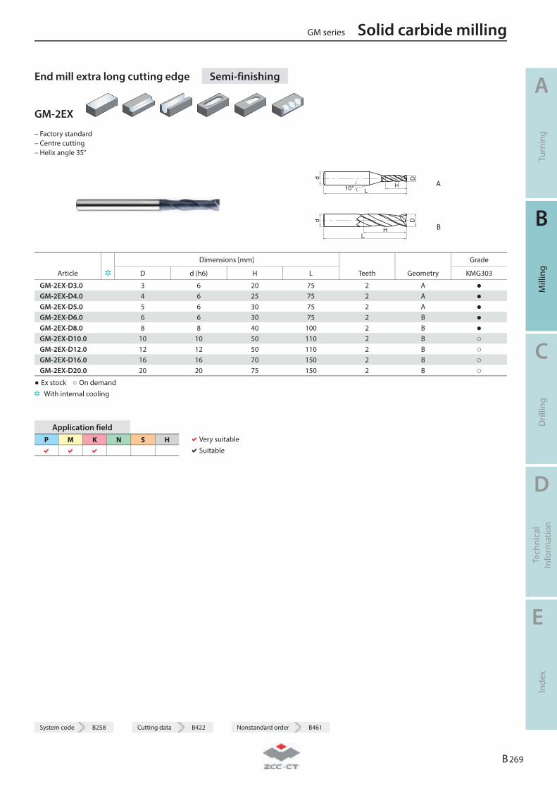
End mill extra long cutting edge Semi-finishing
GM-2EX
– Factory standard – Centre cutting – Helix angle 35°
d
L10° H
D
A
d
LH
D
B
Dimensions [mm] Grade
Article D d (h6) H L Teeth Geometry KMG303
GM-2EX-D3.0 3 6 20 75 2 A ● GM-2EX-D4.0 4 6 25 75 2 A ● GM-2EX-D5.0 5 6 30 75 2 A ● GM-2EX-D6.0 6 6 30 75 2 B ● GM-2EX-D8.0 8 8 40 100 2 B ● GM-2EX-D10.0 10 10 50 110 2 B ○ GM-2EX-D12.0 12 12 50 110 2 B ○ GM-2EX-D16.0 16 16 70 150 2 B ○ GM-2EX-D20.0 20 20 75 150 2 B ○
● Ex stock ○ On demand With internal cooling
Application field P M K N S H
Very suitable Suitable
GM series Solid carbide milling
A
Turn
ing
B
Mill
ing
C
Dril
ling
D
Tech
nica
l In
form
atio
n
E
Inde
x
B 269
System code B258 Cutting data B422 Nonstandard order B461
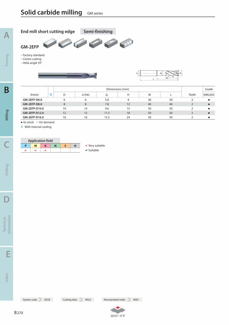
End mill short cutting edge Semi-finishing
GM-2EFP
– Factory standard – Centre cutting – Helix angle 35°
d
L M
d1
H
D
Dimensions [mm] Grade
Article D d (h6) d1 H M L Teeth KMG303
GM-2EFP-D6.0 6 6 5.8 9 30 30 2 ● GM-2EFP-D8.0 8 8 7.8 12 40 40 2 ● GM-2EFP-D10.0 10 10 9.6 15 50 50 2 ● GM-2EFP-D12.0 12 12 11.5 18 50 50 2 ● GM-2EFP-D16.0 16 16 15.5 24 50 50 2 ●
● Ex stock ○ On demand With internal cooling
Application field P M K N S H
Very suitable Suitable
Solid carbide milling GM series
A
Turn
ing
B
Mill
ing
C
Dril
ling
D
Tech
nica
l In
form
atio
n
E
Inde
x
B 270
System code B258 Cutting data B422 Nonstandard order B461
System code B258 Cutting data B422 Nonstandard order B461
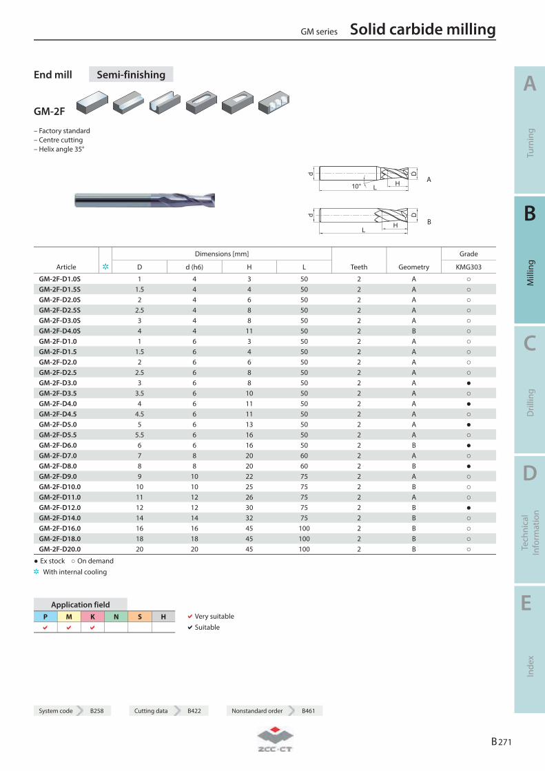
End mill Semi-finishing
GM-2F
– Factory standard – Centre cutting – Helix angle 35°
L
d
H
D
10° A
L
D
H
d
B
Dimensions [mm] Grade
Article D d (h6) H L Teeth Geometry KMG303
GM-2F-D1.0S 1 4 3 50 2 A ○ GM-2F-D1.5S 1.5 4 4 50 2 A ○ GM-2F-D2.0S 2 4 6 50 2 A ○ GM-2F-D2.5S 2.5 4 8 50 2 A ○ GM-2F-D3.0S 3 4 8 50 2 A ○ GM-2F-D4.0S 4 4 11 50 2 B ○ GM-2F-D1.0 1 6 3 50 2 A ○ GM-2F-D1.5 1.5 6 4 50 2 A ○ GM-2F-D2.0 2 6 6 50 2 A ○ GM-2F-D2.5 2.5 6 8 50 2 A ○ GM-2F-D3.0 3 6 8 50 2 A ● GM-2F-D3.5 3.5 6 10 50 2 A ○ GM-2F-D4.0 4 6 11 50 2 A ● GM-2F-D4.5 4.5 6 11 50 2 A ○ GM-2F-D5.0 5 6 13 50 2 A ● GM-2F-D5.5 5.5 6 16 50 2 A ○ GM-2F-D6.0 6 6 16 50 2 B ● GM-2F-D7.0 7 8 20 60 2 A ○ GM-2F-D8.0 8 8 20 60 2 B ● GM-2F-D9.0 9 10 22 75 2 A ○ GM-2F-D10.0 10 10 25 75 2 B ○ GM-2F-D11.0 11 12 26 75 2 A ○ GM-2F-D12.0 12 12 30 75 2 B ● GM-2F-D14.0 14 14 32 75 2 B ○ GM-2F-D16.0 16 16 45 100 2 B ○ GM-2F-D18.0 18 18 45 100 2 B ○ GM-2F-D20.0 20 20 45 100 2 B ○
● Ex stock ○ On demand With internal cooling
Application field P M K N S H
Very suitable Suitable
GM series Solid carbide milling
A
Turn
ing
B
Mill
ing
C
Dril
ling
D
Tech
nica
l In
form
atio
n
E
Inde
x
B 271
System code B258 Cutting data B422 Nonstandard order B461

End mill long cutting edge Semi-finishing
GM-2FL
– Factory standard – Centre cutting – Helix angle 35°
L
d
H
D
10° A
L
Dd
H B
Dimensions [mm] Grade
Article D d (h6) H L Teeth Geometry KMG303
GM-2FL-D3.0 3 6 12 75 2 A ○ GM-2FL-D4.0 4 6 15 75 2 A ○ GM-2FL-D5.0 5 6 20 75 2 A ○ GM-2FL-D6.0 6 6 20 75 2 B ○ GM-2FL-D8.0 8 8 25 100 2 B ○ GM-2FL-D10.0 10 10 30 100 2 B ○ GM-2FL-D12.0 12 12 35 100 2 B ○ GM-2FL-D14.0 14 14 40 100 2 B ○ GM-2FL-D16.0 16 16 50 150 2 B ○ GM-2FL-D20.0 20 20 55 150 2 B ○
● Ex stock ○ On demand With internal cooling
Application field P M K N S H
Very suitable Suitable
Solid carbide milling GM series
A
Turn
ing
B
Mill
ing
C
Dril
ling
D
Tech
nica
l In
form
atio
n
E
Inde
x
B 272
System code B258 Cutting data B422 Nonstandard order B461
System code B258 Cutting data B422 Nonstandard order B461
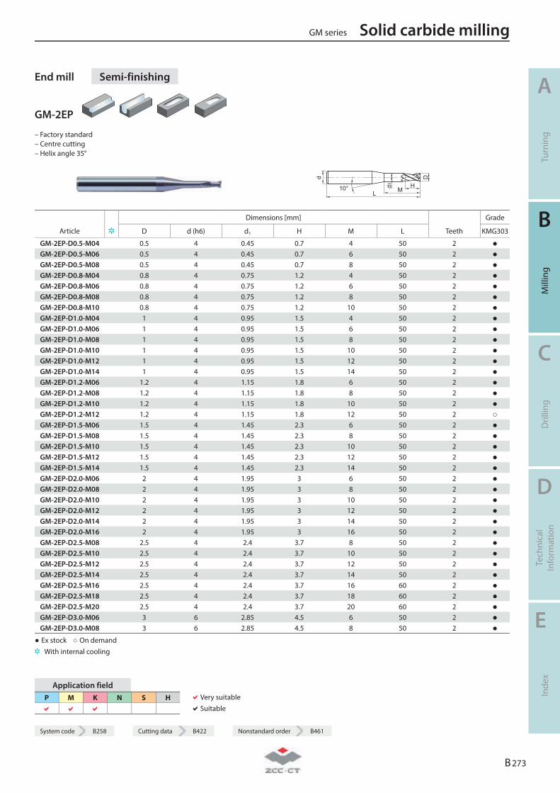
End mill Semi-finishing
GM-2EP
– Factory standard – Centre cutting – Helix angle 35°
L
D
H
d
d1 M10°
Dimensions [mm] Grade
Article D d (h6) d1 H M L Teeth KMG303
GM-2EP-D0.5-M04 0.5 4 0.45 0.7 4 50 2 ● GM-2EP-D0.5-M06 0.5 4 0.45 0.7 6 50 2 ● GM-2EP-D0.5-M08 0.5 4 0.45 0.7 8 50 2 ● GM-2EP-D0.8-M04 0.8 4 0.75 1.2 4 50 2 ● GM-2EP-D0.8-M06 0.8 4 0.75 1.2 6 50 2 ● GM-2EP-D0.8-M08 0.8 4 0.75 1.2 8 50 2 ● GM-2EP-D0.8-M10 0.8 4 0.75 1.2 10 50 2 ● GM-2EP-D1.0-M04 1 4 0.95 1.5 4 50 2 ● GM-2EP-D1.0-M06 1 4 0.95 1.5 6 50 2 ● GM-2EP-D1.0-M08 1 4 0.95 1.5 8 50 2 ● GM-2EP-D1.0-M10 1 4 0.95 1.5 10 50 2 ● GM-2EP-D1.0-M12 1 4 0.95 1.5 12 50 2 ● GM-2EP-D1.0-M14 1 4 0.95 1.5 14 50 2 ● GM-2EP-D1.2-M06 1.2 4 1.15 1.8 6 50 2 ● GM-2EP-D1.2-M08 1.2 4 1.15 1.8 8 50 2 ● GM-2EP-D1.2-M10 1.2 4 1.15 1.8 10 50 2 ● GM-2EP-D1.2-M12 1.2 4 1.15 1.8 12 50 2 ○ GM-2EP-D1.5-M06 1.5 4 1.45 2.3 6 50 2 ● GM-2EP-D1.5-M08 1.5 4 1.45 2.3 8 50 2 ● GM-2EP-D1.5-M10 1.5 4 1.45 2.3 10 50 2 ● GM-2EP-D1.5-M12 1.5 4 1.45 2.3 12 50 2 ● GM-2EP-D1.5-M14 1.5 4 1.45 2.3 14 50 2 ● GM-2EP-D2.0-M06 2 4 1.95 3 6 50 2 ● GM-2EP-D2.0-M08 2 4 1.95 3 8 50 2 ● GM-2EP-D2.0-M10 2 4 1.95 3 10 50 2 ● GM-2EP-D2.0-M12 2 4 1.95 3 12 50 2 ● GM-2EP-D2.0-M14 2 4 1.95 3 14 50 2 ● GM-2EP-D2.0-M16 2 4 1.95 3 16 50 2 ● GM-2EP-D2.5-M08 2.5 4 2.4 3.7 8 50 2 ● GM-2EP-D2.5-M10 2.5 4 2.4 3.7 10 50 2 ● GM-2EP-D2.5-M12 2.5 4 2.4 3.7 12 50 2 ● GM-2EP-D2.5-M14 2.5 4 2.4 3.7 14 50 2 ● GM-2EP-D2.5-M16 2.5 4 2.4 3.7 16 60 2 ● GM-2EP-D2.5-M18 2.5 4 2.4 3.7 18 60 2 ● GM-2EP-D2.5-M20 2.5 4 2.4 3.7 20 60 2 ● GM-2EP-D3.0-M06 3 6 2.85 4.5 6 50 2 ● GM-2EP-D3.0-M08 3 6 2.85 4.5 8 50 2 ●
● Ex stock ○ On demand With internal cooling
Application field P M K N S H
Very suitable Suitable
GM series Solid carbide milling
A
Turn
ing
B
Mill
ing
C
Dril
ling
D
Tech
nica
l In
form
atio
n
E
Inde
x
B 273
System code B258 Cutting data B422 Nonstandard order B461
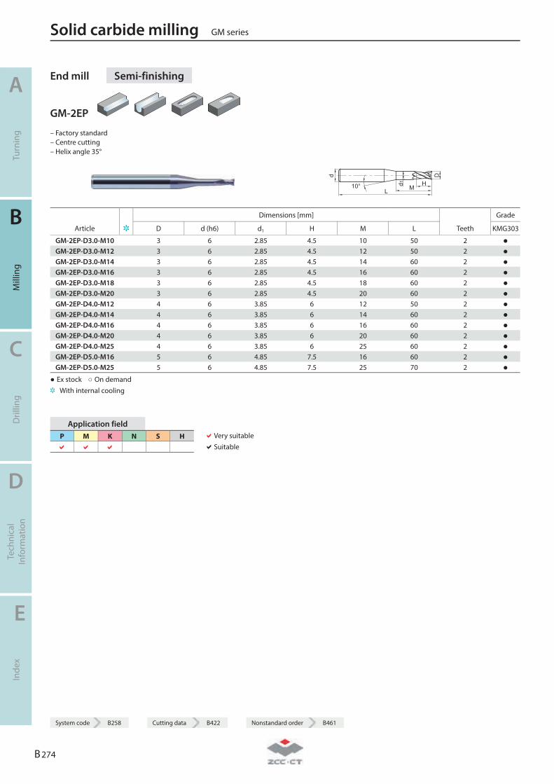
End mill Semi-finishing
GM-2EP
– Factory standard – Centre cutting – Helix angle 35°
L
D
H
d
d1 M10°
Dimensions [mm] Grade
Article D d (h6) d1 H M L Teeth KMG303
GM-2EP-D3.0-M10 3 6 2.85 4.5 10 50 2 ● GM-2EP-D3.0-M12 3 6 2.85 4.5 12 50 2 ● GM-2EP-D3.0-M14 3 6 2.85 4.5 14 60 2 ● GM-2EP-D3.0-M16 3 6 2.85 4.5 16 60 2 ● GM-2EP-D3.0-M18 3 6 2.85 4.5 18 60 2 ● GM-2EP-D3.0-M20 3 6 2.85 4.5 20 60 2 ● GM-2EP-D4.0-M12 4 6 3.85 6 12 50 2 ● GM-2EP-D4.0-M14 4 6 3.85 6 14 60 2 ● GM-2EP-D4.0-M16 4 6 3.85 6 16 60 2 ● GM-2EP-D4.0-M20 4 6 3.85 6 20 60 2 ● GM-2EP-D4.0-M25 4 6 3.85 6 25 60 2 ● GM-2EP-D5.0-M16 5 6 4.85 7.5 16 60 2 ● GM-2EP-D5.0-M25 5 6 4.85 7.5 25 70 2 ●
● Ex stock ○ On demand With internal cooling
Application field P M K N S H
Very suitable Suitable
Solid carbide milling GM series
A
Turn
ing
B
Mill
ing
C
Dril
ling
D
Tech
nica
l In
form
atio
n
E
Inde
x
B 274
System code B258 Cutting data B422 Nonstandard order B461
System code B258 Cutting data B422 Nonstandard order B461
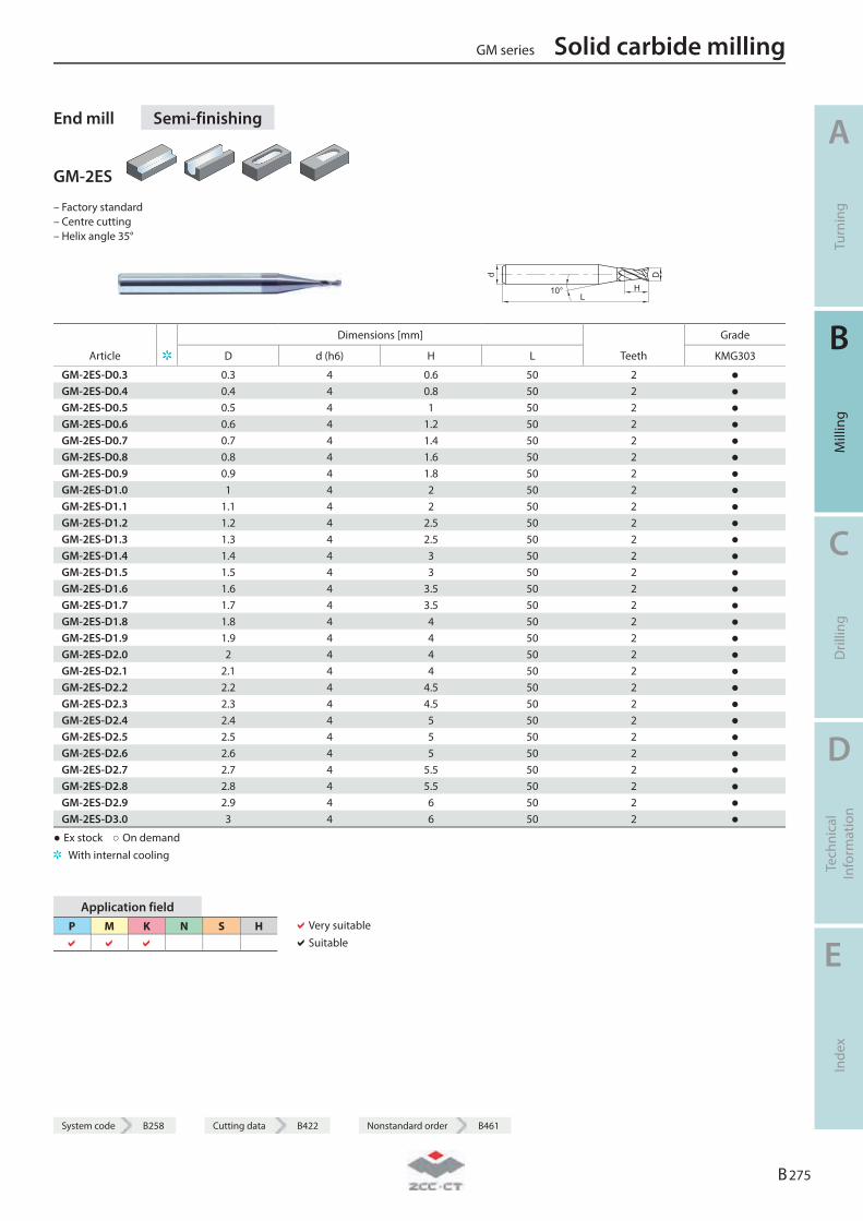
End mill Semi-finishing
GM-2ES
– Factory standard – Centre cutting – Helix angle 35°
L
D
H
d
10°
Dimensions [mm] Grade
Article D d (h6) H L Teeth KMG303
GM-2ES-D0.3 0.3 4 0.6 50 2 ● GM-2ES-D0.4 0.4 4 0.8 50 2 ● GM-2ES-D0.5 0.5 4 1 50 2 ● GM-2ES-D0.6 0.6 4 1.2 50 2 ● GM-2ES-D0.7 0.7 4 1.4 50 2 ● GM-2ES-D0.8 0.8 4 1.6 50 2 ● GM-2ES-D0.9 0.9 4 1.8 50 2 ● GM-2ES-D1.0 1 4 2 50 2 ● GM-2ES-D1.1 1.1 4 2 50 2 ● GM-2ES-D1.2 1.2 4 2.5 50 2 ● GM-2ES-D1.3 1.3 4 2.5 50 2 ● GM-2ES-D1.4 1.4 4 3 50 2 ● GM-2ES-D1.5 1.5 4 3 50 2 ● GM-2ES-D1.6 1.6 4 3.5 50 2 ● GM-2ES-D1.7 1.7 4 3.5 50 2 ● GM-2ES-D1.8 1.8 4 4 50 2 ● GM-2ES-D1.9 1.9 4 4 50 2 ● GM-2ES-D2.0 2 4 4 50 2 ● GM-2ES-D2.1 2.1 4 4 50 2 ● GM-2ES-D2.2 2.2 4 4.5 50 2 ● GM-2ES-D2.3 2.3 4 4.5 50 2 ● GM-2ES-D2.4 2.4 4 5 50 2 ● GM-2ES-D2.5 2.5 4 5 50 2 ● GM-2ES-D2.6 2.6 4 5 50 2 ● GM-2ES-D2.7 2.7 4 5.5 50 2 ● GM-2ES-D2.8 2.8 4 5.5 50 2 ● GM-2ES-D2.9 2.9 4 6 50 2 ● GM-2ES-D3.0 3 4 6 50 2 ●
● Ex stock ○ On demand With internal cooling
Application field P M K N S H
Very suitable Suitable
GM series Solid carbide milling
A
Turn
ing
B
Mill
ing
C
Dril
ling
D
Tech
nica
l In
form
atio
n
E
Inde
x
B 275
System code B258 Cutting data B422 Nonstandard order B461
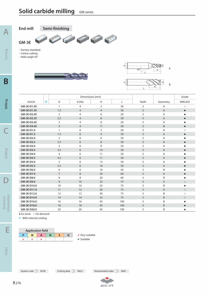
End mill Semi-finishing
GM-3E
– Factory standard – Centre cutting – Helix angle 45°
d
L10° H
D
A
d
LH
D
B
Dimensions [mm] Grade
Article D d (h6) H L Teeth Geometry KMG303
GM-3E-D1.0S 1 4 3 50 3 A ○ GM-3E-D1.5S 1.5 4 4 50 3 A ● GM-3E-D2.0S 2 4 6 50 3 A ● GM-3E-D2.5S 2.5 4 8 50 3 A ● GM-3E-D3.0S 3 4 8 50 3 A ● GM-3E-D4.0S 4 4 11 50 3 B ● GM-3E-D1.0 1 6 3 50 3 A ○ GM-3E-D1.5 1.5 6 4 50 3 A ● GM-3E-D2.0 2 6 6 50 3 A ● GM-3E-D2.5 2.5 6 8 50 3 A ● GM-3E-D3.0 3 6 8 50 3 A ● GM-3E-D3.5 3.5 6 10 50 3 A ● GM-3E-D4.0 4 6 11 50 3 A ● GM-3E-D4.5 4.5 6 11 50 3 A ● GM-3E-D5.0 5 6 13 50 3 A ● GM-3E-D5.5 5.5 6 16 50 3 A ● GM-3E-D6.0 6 6 16 50 3 B ● GM-3E-D7.0 7 8 20 60 3 A ● GM-3E-D8.0 8 8 20 60 3 B ● GM-3E-D9.0 9 10 22 75 3 A ○ GM-3E-D10.0 10 10 25 75 3 B ● GM-3E-D11.0 11 12 26 75 3 A ○ GM-3E-D12.0 12 12 30 75 3 B ○ GM-3E-D14.0 14 14 32 75 3 B ○ GM-3E-D16.0 16 16 45 100 3 B ● GM-3E-D18.0 18 18 45 100 3 B ● GM-3E-D20.0 20 20 45 100 3 B ●
● Ex stock ○ On demand With internal cooling
Application field P M K N S H
Very suitable Suitable
Solid carbide milling GM series
A
Turn
ing
B
Mill
ing
C
Dril
ling
D
Tech
nica
l In
form
atio
n
E
Inde
x
B 276
System code B258 Cutting data B422 Nonstandard order B461

System code B258 Cutting data B422 Nonstandard order B461
End mill long cutting edge Semi-finishing
GM-3EL
– Factory standard – Centre cutting – Helix angle 45°
d
L10° H
D
A
d
LH
D
B
Dimensions [mm] Grade
Article D d (h6) H L Teeth Geometry KMG303
GM-3EL-D3.0 3 6 12 75 3 A ● GM-3EL-D4.0 4 6 15 75 3 A ● GM-3EL-D5.0 5 6 20 75 3 A ● GM-3EL-D6.0 6 6 20 75 3 B ● GM-3EL-D8.0 8 8 25 100 3 B ● GM-3EL-D10.0 10 10 30 100 3 B ● GM-3EL-D12.0 12 12 35 100 3 B ● GM-3EL-D14.0 14 14 40 100 3 B ● GM-3EL-D16.0 16 16 50 150 3 B ● GM-3EL-D20.0 20 20 55 150 3 B ●
● Ex stock ○ On demand With internal cooling
Application field P M K N S H
Very suitable Suitable
GM series Solid carbide milling
A
Turn
ing
B
Mill
ing
C
Dril
ling
D
Tech
nica
l In
form
atio
n
E
Inde
x
B 277
System code B258 Cutting data B422 Nonstandard order B461
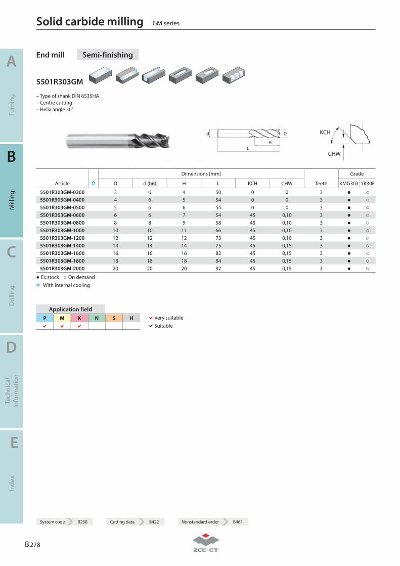
End mill Semi-finishing
5501R303GM
– Type of shank DIN 6535HA – Centre cutting – Helix angle 30°
LH
Dd
KCH
CHW
Dimensions [mm] Grade
Article D d (h6) H L KCH CHW Teeth KMG303 YK30F
5501R303GM-0300 3 6 4 50 0 0 3 ● ○ 5501R303GM-0400 4 6 5 54 0 0 3 ● ○ 5501R303GM-0500 5 6 6 54 0 0 3 ● ○ 5501R303GM-0600 6 6 7 54 45 0,10 3 ● ○ 5501R303GM-0800 8 8 9 58 45 0,10 3 ● ○ 5501R303GM-1000 10 10 11 66 45 0,10 3 ● ○ 5501R303GM-1200 12 12 12 73 45 0,10 3 ● ○ 5501R303GM-1400 14 14 14 75 45 0,15 3 ● ○ 5501R303GM-1600 16 16 16 82 45 0,15 3 ● ○ 5501R303GM-1800 18 18 18 84 45 0,15 3 ● ○ 5501R303GM-2000 20 20 20 92 45 0,15 3 ● ○
● Ex stock ○ On demand With internal cooling
Application field P M K N S H
Very suitable Suitable
Solid carbide milling GM series
A
Turn
ing
B
Mill
ing
C
Dril
ling
D
Tech
nica
l In
form
atio
n
E
Inde
x
B 278
System code B258 Cutting data B422 Nonstandard order B461
System code B258 Cutting data B422 Nonstandard order B461
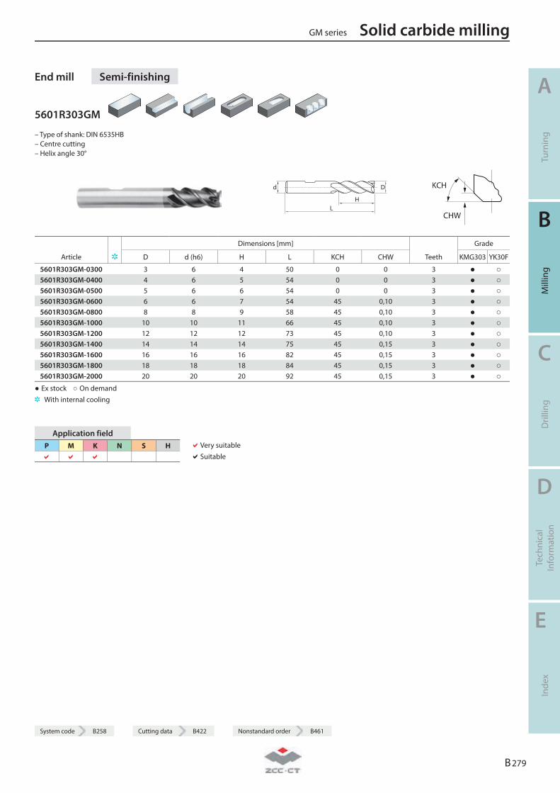
End mill Semi-finishing
5601R303GM
– Type of shank: DIN 6535HB – Centre cutting – Helix angle 30°
LH
Dd
KCH
CHW
Dimensions [mm] Grade
Article D d (h6) H L KCH CHW Teeth KMG303 YK30F
5601R303GM-0300 3 6 4 50 0 0 3 ● ○ 5601R303GM-0400 4 6 5 54 0 0 3 ● ○ 5601R303GM-0500 5 6 6 54 0 0 3 ● ○ 5601R303GM-0600 6 6 7 54 45 0,10 3 ● ○ 5601R303GM-0800 8 8 9 58 45 0,10 3 ● ○ 5601R303GM-1000 10 10 11 66 45 0,10 3 ● ○ 5601R303GM-1200 12 12 12 73 45 0,10 3 ● ○ 5601R303GM-1400 14 14 14 75 45 0,15 3 ● ○ 5601R303GM-1600 16 16 16 82 45 0,15 3 ● ○ 5601R303GM-1800 18 18 18 84 45 0,15 3 ● ○ 5601R303GM-2000 20 20 20 92 45 0,15 3 ● ○
● Ex stock ○ On demand With internal cooling
Application field P M K N S H
Very suitable Suitable
GM series Solid carbide milling
A
Turn
ing
B
Mill
ing
C
Dril
ling
D
Tech
nica
l In
form
atio
n
E
Inde
x
B 279
System code B258 Cutting data B422 Nonstandard order B461
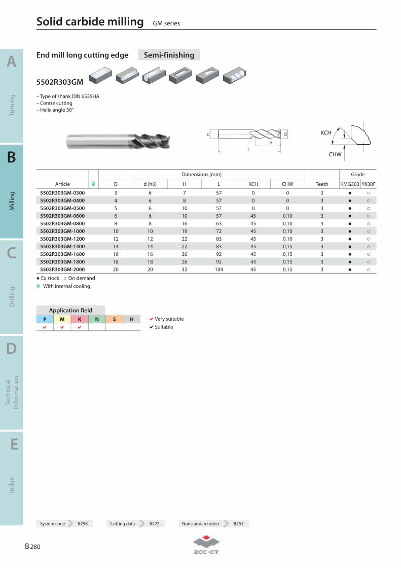
End mill long cutting edge Semi-finishing
5502R303GM
– Type of shank DIN 6535HA – Centre cutting – Helix angle 30°
LH
Dd
KCH
CHW
Dimensions [mm] Grade
Article D d (h6) H L KCH CHW Teeth KMG303 YK30F
5502R303GM-0300 3 6 7 57 0 0 3 ● ○ 5502R303GM-0400 4 6 8 57 0 0 3 ● ○ 5502R303GM-0500 5 6 10 57 0 0 3 ● ○ 5502R303GM-0600 6 6 10 57 45 0,10 3 ● ○ 5502R303GM-0800 8 8 16 63 45 0,10 3 ● ○ 5502R303GM-1000 10 10 19 72 45 0,10 3 ● ○ 5502R303GM-1200 12 12 22 83 45 0,10 3 ● ○ 5502R303GM-1400 14 14 22 83 45 0,15 3 ● ○ 5502R303GM-1600 16 16 26 92 45 0,15 3 ● ○ 5502R303GM-1800 18 18 26 92 45 0,15 3 ● ○ 5502R303GM-2000 20 20 32 104 45 0,15 3 ● ○
● Ex stock ○ On demand With internal cooling
Application field P M K N S H
Very suitable Suitable
Solid carbide milling GM series
A
Turn
ing
B
Mill
ing
C
Dril
ling
D
Tech
nica
l In
form
atio
n
E
Inde
x
B 280
System code B258 Cutting data B422 Nonstandard order B461
System code B258 Cutting data B422 Nonstandard order B461
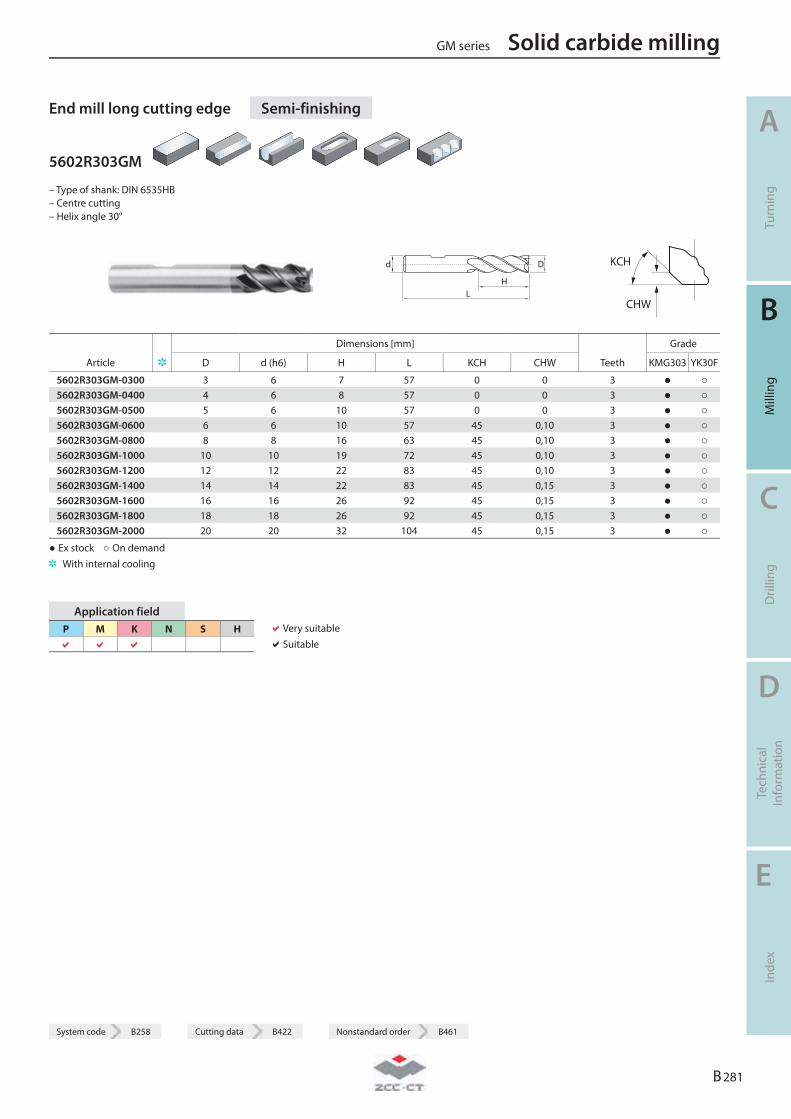
End mill long cutting edge Semi-finishing
5602R303GM
– Type of shank: DIN 6535HB – Centre cutting – Helix angle 30°
LH
Dd
KCH
CHW
Dimensions [mm] Grade
Article D d (h6) H L KCH CHW Teeth KMG303 YK30F
5602R303GM-0300 3 6 7 57 0 0 3 ● ○ 5602R303GM-0400 4 6 8 57 0 0 3 ● ○ 5602R303GM-0500 5 6 10 57 0 0 3 ● ○ 5602R303GM-0600 6 6 10 57 45 0,10 3 ● ○ 5602R303GM-0800 8 8 16 63 45 0,10 3 ● ○ 5602R303GM-1000 10 10 19 72 45 0,10 3 ● ○ 5602R303GM-1200 12 12 22 83 45 0,10 3 ● ○ 5602R303GM-1400 14 14 22 83 45 0,15 3 ● ○ 5602R303GM-1600 16 16 26 92 45 0,15 3 ● ○ 5602R303GM-1800 18 18 26 92 45 0,15 3 ● ○ 5602R303GM-2000 20 20 32 104 45 0,15 3 ● ○
● Ex stock ○ On demand With internal cooling
Application field P M K N S H
Very suitable Suitable
GM series Solid carbide milling
A
Turn
ing
B
Mill
ing
C
Dril
ling
D
Tech
nica
l In
form
atio
n
E
Inde
x
B 281
System code B258 Cutting data B422 Nonstandard order B461
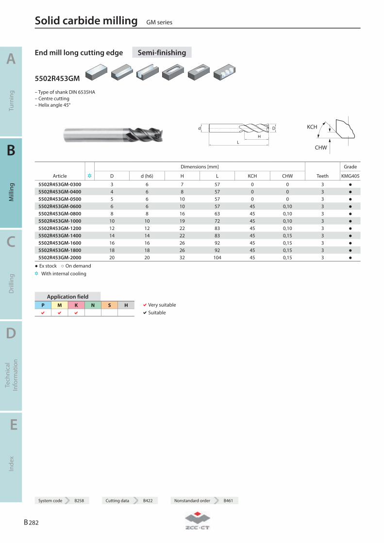
End mill long cutting edge Semi-finishing
5502R453GM
– Type of shank DIN 6535HA – Centre cutting – Helix angle 45°
LH
Dd
KCH
CHW
Dimensions [mm] Grade
Article D d (h6) H L KCH CHW Teeth KMG405
5502R453GM-0300 3 6 7 57 0 0 3 ● 5502R453GM-0400 4 6 8 57 0 0 3 ● 5502R453GM-0500 5 6 10 57 0 0 3 ● 5502R453GM-0600 6 6 10 57 45 0,10 3 ● 5502R453GM-0800 8 8 16 63 45 0,10 3 ● 5502R453GM-1000 10 10 19 72 45 0,10 3 ● 5502R453GM-1200 12 12 22 83 45 0,10 3 ● 5502R453GM-1400 14 14 22 83 45 0,15 3 ● 5502R453GM-1600 16 16 26 92 45 0,15 3 ● 5502R453GM-1800 18 18 26 92 45 0,15 3 ● 5502R453GM-2000 20 20 32 104 45 0,15 3 ●
● Ex stock ○ On demand With internal cooling
Application field P M K N S H
Very suitable Suitable
Solid carbide milling GM series
A
Turn
ing
B
Mill
ing
C
Dril
ling
D
Tech
nica
l In
form
atio
n
E
Inde
x
B 282
System code B258 Cutting data B422 Nonstandard order B461

System code B258 Cutting data B422 Nonstandard order B461
End mill long cutting edge Semi-finishing
5602R453GM
– Type of shank: DIN 6535HB – Centre cutting – Helix angle 45°
LH
Dd
KCH
CHW
Dimensions [mm] Grade
Article D d (h6) H L KCH CHW Teeth KMG303 KMG405
5602R453GM-0300 3 6 7 57 0 0 3 ● ● 5602R453GM-0400 4 6 8 57 0 0 3 ● ● 5602R453GM-0500 5 6 10 57 0 0 3 ● ● 5602R453GM-0600 6 6 10 57 45 0,10 3 ● ● 5602R453GM-0800 8 8 16 63 45 0,10 3 ● ● 5602R453GM-1000 10 10 19 72 45 0,10 3 ● ● 5602R453GM-1200 12 12 22 83 45 0,10 3 ● ● 5602R453GM-1400 14 14 22 83 45 0,15 3 ● ● 5602R453GM-1600 16 16 26 92 45 0,15 3 ● ● 5602R453GM-1800 18 18 26 92 45 0,15 3 ● ● 5602R453GM-2000 20 20 32 104 45 0,15 3 ● ●
● Ex stock ○ On demand With internal cooling
Application field P M K N S H
Very suitable Suitable
GM series Solid carbide milling
A
Turn
ing
B
Mill
ing
C
Dril
ling
D
Tech
nica
l In
form
atio
n
E
Inde
x
B 283
System code B258 Cutting data B422 Nonstandard order B461
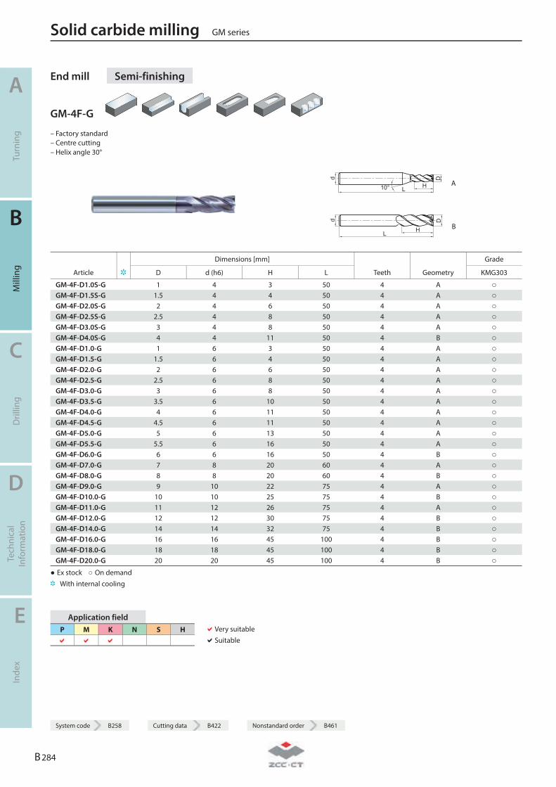
End mill Semi-finishing
GM-4F-G
– Factory standard – Centre cutting – Helix angle 30°
d
L10° H
D
A
d
L H
D
B
Dimensions [mm] Grade
Article D d (h6) H L Teeth Geometry KMG303
GM-4F-D1.0S-G 1 4 3 50 4 A ○ GM-4F-D1.5S-G 1.5 4 4 50 4 A ○ GM-4F-D2.0S-G 2 4 6 50 4 A ○ GM-4F-D2.5S-G 2.5 4 8 50 4 A ○ GM-4F-D3.0S-G 3 4 8 50 4 A ○ GM-4F-D4.0S-G 4 4 11 50 4 B ○ GM-4F-D1.0-G 1 6 3 50 4 A ○ GM-4F-D1.5-G 1.5 6 4 50 4 A ○ GM-4F-D2.0-G 2 6 6 50 4 A ○ GM-4F-D2.5-G 2.5 6 8 50 4 A ○ GM-4F-D3.0-G 3 6 8 50 4 A ○ GM-4F-D3.5-G 3.5 6 10 50 4 A ○ GM-4F-D4.0-G 4 6 11 50 4 A ○ GM-4F-D4.5-G 4.5 6 11 50 4 A ○ GM-4F-D5.0-G 5 6 13 50 4 A ○ GM-4F-D5.5-G 5.5 6 16 50 4 A ○ GM-4F-D6.0-G 6 6 16 50 4 B ○ GM-4F-D7.0-G 7 8 20 60 4 A ○ GM-4F-D8.0-G 8 8 20 60 4 B ○ GM-4F-D9.0-G 9 10 22 75 4 A ○ GM-4F-D10.0-G 10 10 25 75 4 B ○ GM-4F-D11.0-G 11 12 26 75 4 A ○ GM-4F-D12.0-G 12 12 30 75 4 B ○ GM-4F-D14.0-G 14 14 32 75 4 B ○ GM-4F-D16.0-G 16 16 45 100 4 B ○ GM-4F-D18.0-G 18 18 45 100 4 B ○ GM-4F-D20.0-G 20 20 45 100 4 B ○
● Ex stock ○ On demand With internal cooling
Application field P M K N S H
Very suitable Suitable
Solid carbide milling GM series
A
Turn
ing
B
Mill
ing
C
Dril
ling
D
Tech
nica
l In
form
atio
n
E
Inde
x
B 284
System code B258 Cutting data B422 Nonstandard order B461
System code B258 Cutting data B422 Nonstandard order B461
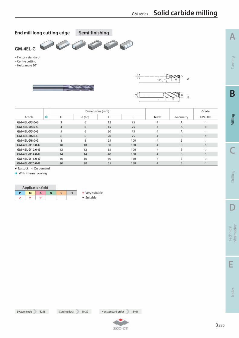
End mill long cutting edge Semi-finishing
GM-4EL-G
– Factory standard – Centre cutting – Helix angle 30°
d
L10° H
D
A
d
L H
D
B
Dimensions [mm] Grade
Article D d (h6) H L Teeth Geometry KMG303
GM-4EL-D3.0-G 3 6 12 75 4 A ○ GM-4EL-D4.0-G 4 6 15 75 4 A ○ GM-4EL-D5.0-G 5 6 20 75 4 A ○ GM-4EL-D6.0-G 6 6 20 75 4 B ○ GM-4EL-D8.0-G 8 8 25 100 4 B ○ GM-4EL-D10.0-G 10 10 30 100 4 B ○ GM-4EL-D12.0-G 12 12 35 100 4 B ○ GM-4EL-D14.0-G 14 14 40 100 4 B ○ GM-4EL-D16.0-G 16 16 50 150 4 B ○ GM-4EL-D20.0-G 20 20 55 150 4 B ○
● Ex stock ○ On demand With internal cooling
Application field P M K N S H
Very suitable Suitable
GM series Solid carbide milling
A
Turn
ing
B
Mill
ing
C
Dril
ling
D
Tech
nica
l In
form
atio
n
E
Inde
x
B 285
System code B258 Cutting data B422 Nonstandard order B461
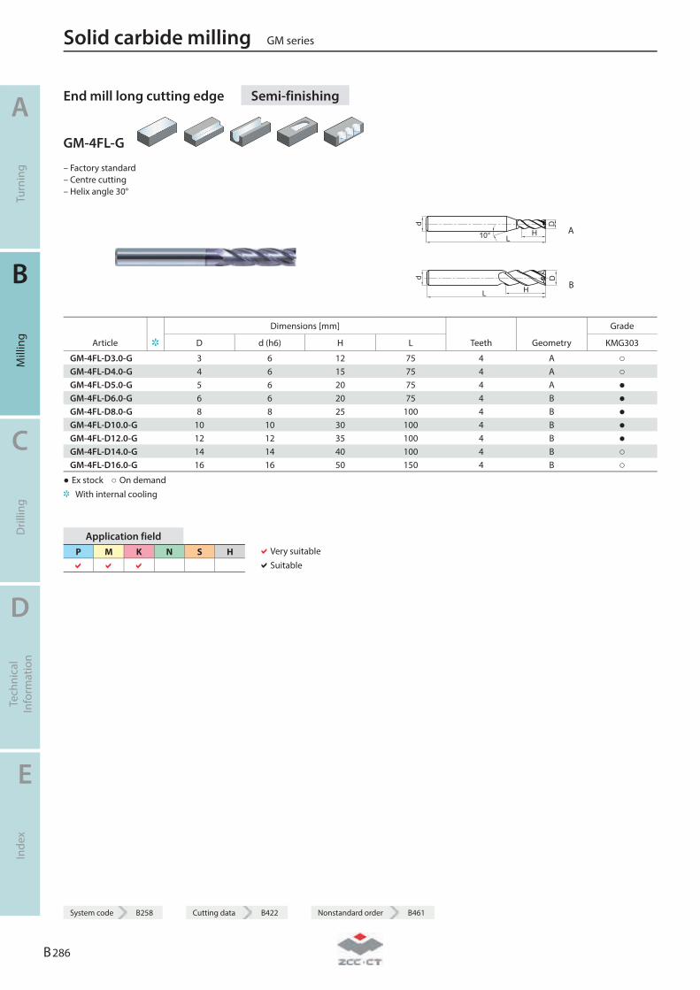
End mill long cutting edge Semi-finishing
GM-4FL-G
– Factory standard – Centre cutting – Helix angle 30°
d
L10° H
D
A
d
L H
D
B
Dimensions [mm] Grade
Article D d (h6) H L Teeth Geometry KMG303
GM-4FL-D3.0-G 3 6 12 75 4 A ○ GM-4FL-D4.0-G 4 6 15 75 4 A ○ GM-4FL-D5.0-G 5 6 20 75 4 A ● GM-4FL-D6.0-G 6 6 20 75 4 B ● GM-4FL-D8.0-G 8 8 25 100 4 B ● GM-4FL-D10.0-G 10 10 30 100 4 B ● GM-4FL-D12.0-G 12 12 35 100 4 B ● GM-4FL-D14.0-G 14 14 40 100 4 B ○ GM-4FL-D16.0-G 16 16 50 150 4 B ○
● Ex stock ○ On demand With internal cooling
Application field P M K N S H
Very suitable Suitable
Solid carbide milling GM series
A
Turn
ing
B
Mill
ing
C
Dril
ling
D
Tech
nica
l In
form
atio
n
E
Inde
x
B 286
System code B258 Cutting data B422 Nonstandard order B461
System code B258 Cutting data B422 Nonstandard order B461
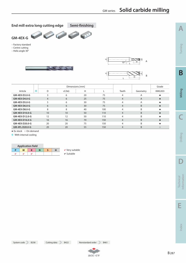
End mill extra long cutting edge Semi-finishing
GM-4EX-G
– Factory standard – Centre cutting – Helix angle 30°
d
L10° H
D
A
d
L H
D
B
Dimensions [mm] Grade
Article D d (h6) H L Teeth Geometry KMG303
GM-4EX-D3.0-G 3 6 20 75 4 A ● GM-4EX-D4.0-G 4 6 25 75 4 A ● GM-4EX-D5.0-G 5 6 30 75 4 A ● GM-4EX-D6.0-G 6 6 30 75 4 B ● GM-4EX-D8.0-G 8 8 40 100 4 B ● GM-4EX-D10.0-G 10 10 50 110 4 B ● GM-4EX-D12.0-G 12 12 50 110 4 B ● GM-4EX-D16.0-G 16 16 70 150 4 B ● GM-4EX-D20.0-G 20 20 75 150 4 B ● GM-4FL-D20.0-G 20 20 55 150 4 B ○
● Ex stock ○ On demand With internal cooling
Application field P M K N S H
Very suitable Suitable
GM series Solid carbide milling
A
Turn
ing
B
Mill
ing
C
Dril
ling
D
Tech
nica
l In
form
atio
n
E
Inde
x
B 287
System code B258 Cutting data B422 Nonstandard order B461

End mill Semi-finishing
GM-4E
– Factory standard – Centre cutting – Helix angle 45°
L
D
H10°
d
A
LH
Dd
B
Dimensions [mm] Grade
Article D d (h6) H L Teeth Geometry KMG303
GM-4E-D1.0S 1 4 3 50 4 A ● GM-4E-D1.5S 1.5 4 4 50 4 A ● GM-4E-D2.0S 2 4 6 50 4 A ● GM-4E-D2.5S 2.5 4 8 50 4 A ● GM-4E-D3.0S 3 4 8 50 4 A ● GM-4E-D4.0S 4 4 11 50 4 B ● GM-4E-D1.0 1 6 3 50 4 A ● GM-4E-D1.5 1.5 6 4 50 4 A ● GM-4E-D2.0 2 6 6 50 4 A ● GM-4E-D2.5 2.5 6 8 50 4 A ● GM-4E-D3.0 3 6 8 50 4 A ● GM-4E-D3.5 3.5 6 10 50 4 A ● GM-4E-D4.0 4 6 11 50 4 A ● GM-4E-D4.5 4.5 6 11 50 4 A ● GM-4E-D5.0 5 6 13 50 4 A ● GM-4E-D5.5 5.5 6 16 50 4 A ● GM-4E-D6.0 6 6 16 50 4 B ● GM-4E-D7.0 7 8 20 60 4 A ● GM-4E-D8.0 8 8 20 60 4 B ● GM-4E-D9.0 9 10 22 75 4 A ● GM-4E-D10.0 10 10 25 75 4 B ● GM-4E-D11.0 11 12 26 75 4 A ● GM-4E-D12.0 12 12 30 75 4 B ● GM-4E-D14.0 14 14 32 75 4 B ● GM-4E-D16.0 16 16 45 100 4 B ● GM-4E-D18.0 18 18 45 100 4 B ● GM-4E-D20.0 20 20 45 100 4 B ●
● Ex stock ○ On demand With internal cooling
Application field P M K N S H
Very suitable Suitable
Solid carbide milling GM series
A
Turn
ing
B
Mill
ing
C
Dril
ling
D
Tech
nica
l In
form
atio
n
E
Inde
x
B 288
System code B258 Cutting data B422 Nonstandard order B461
System code B258 Cutting data B422 Nonstandard order B461
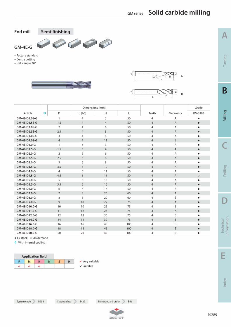
End mill Semi-finishing
GM-4E-G
– Factory standard – Centre cutting – Helix angle 30°
d
L10° H
D
A
d
L H
D
B
Dimensions [mm] Grade
Article D d (h6) H L Teeth Geometry KMG303
GM-4E-D1.0S-G 1 4 3 50 4 A ● GM-4E-D1.5S-G 1.5 4 4 50 4 A ● GM-4E-D2.0S-G 2 4 6 50 4 A ● GM-4E-D2.5S-G 2.5 4 8 50 4 A ● GM-4E-D3.0S-G 3 4 8 50 4 A ● GM-4E-D4.0S-G 4 4 11 50 4 B ● GM-4E-D1.0-G 1 6 3 50 4 A ● GM-4E-D1.5-G 1.5 6 4 50 4 A ● GM-4E-D2.0-G 2 6 6 50 4 A ● GM-4E-D2.5-G 2.5 6 8 50 4 A ● GM-4E-D3.0-G 3 6 8 50 4 A ● GM-4E-D3.5-G 3.5 6 10 50 4 A ● GM-4E-D4.0-G 4 6 11 50 4 A ● GM-4E-D4.5-G 4.5 6 11 50 4 A ○ GM-4E-D5.0-G 5 6 13 50 4 A ● GM-4E-D5.5-G 5.5 6 16 50 4 A ● GM-4E-D6.0-G 6 6 16 50 4 B ● GM-4E-D7.0-G 7 8 20 60 4 A ● GM-4E-D8.0-G 8 8 20 60 4 B ● GM-4E-D9.0-G 9 10 22 75 4 A ● GM-4E-D10.0-G 10 10 25 75 4 B ● GM-4E-D11.0-G 11 12 26 75 4 A ● GM-4E-D12.0-G 12 12 30 75 4 B ● GM-4E-D14.0-G 14 14 32 75 4 B ● GM-4E-D16.0-G 16 16 45 100 4 B ● GM-4E-D18.0-G 18 18 45 100 4 B ● GM-4E-D20.0-G 20 20 45 100 4 B ●
● Ex stock ○ On demand With internal cooling
Application field P M K N S H
Very suitable Suitable
GM series Solid carbide milling
A
Turn
ing
B
Mill
ing
C
Dril
ling
D
Tech
nica
l In
form
atio
n
E
Inde
x
B 289
System code B258 Cutting data B422 Nonstandard order B461
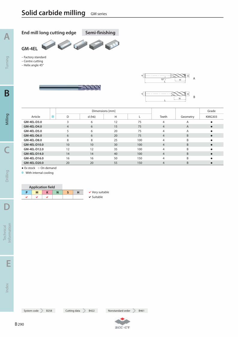
End mill long cutting edge Semi-finishing
GM-4EL
– Factory standard – Centre cutting – Helix angle 45°
L
D
H10°
d
A
LH
Dd
B
Dimensions [mm] Grade
Article D d (h6) H L Teeth Geometry KMG303
GM-4EL-D3.0 3 6 12 75 4 A ● GM-4EL-D4.0 4 6 15 75 4 A ● GM-4EL-D5.0 5 6 20 75 4 A ● GM-4EL-D6.0 6 6 20 75 4 B ● GM-4EL-D8.0 8 8 25 100 4 B ● GM-4EL-D10.0 10 10 30 100 4 B ● GM-4EL-D12.0 12 12 35 100 4 B ● GM-4EL-D14.0 14 14 40 100 4 B ● GM-4EL-D16.0 16 16 50 150 4 B ● GM-4EL-D20.0 20 20 55 150 4 B ●
● Ex stock ○ On demand With internal cooling
Application field P M K N S H
Very suitable Suitable
Solid carbide milling GM series
A
Turn
ing
B
Mill
ing
C
Dril
ling
D
Tech
nica
l In
form
atio
n
E
Inde
x
B 290
System code B258 Cutting data B422 Nonstandard order B461
System code B258 Cutting data B422 Nonstandard order B461
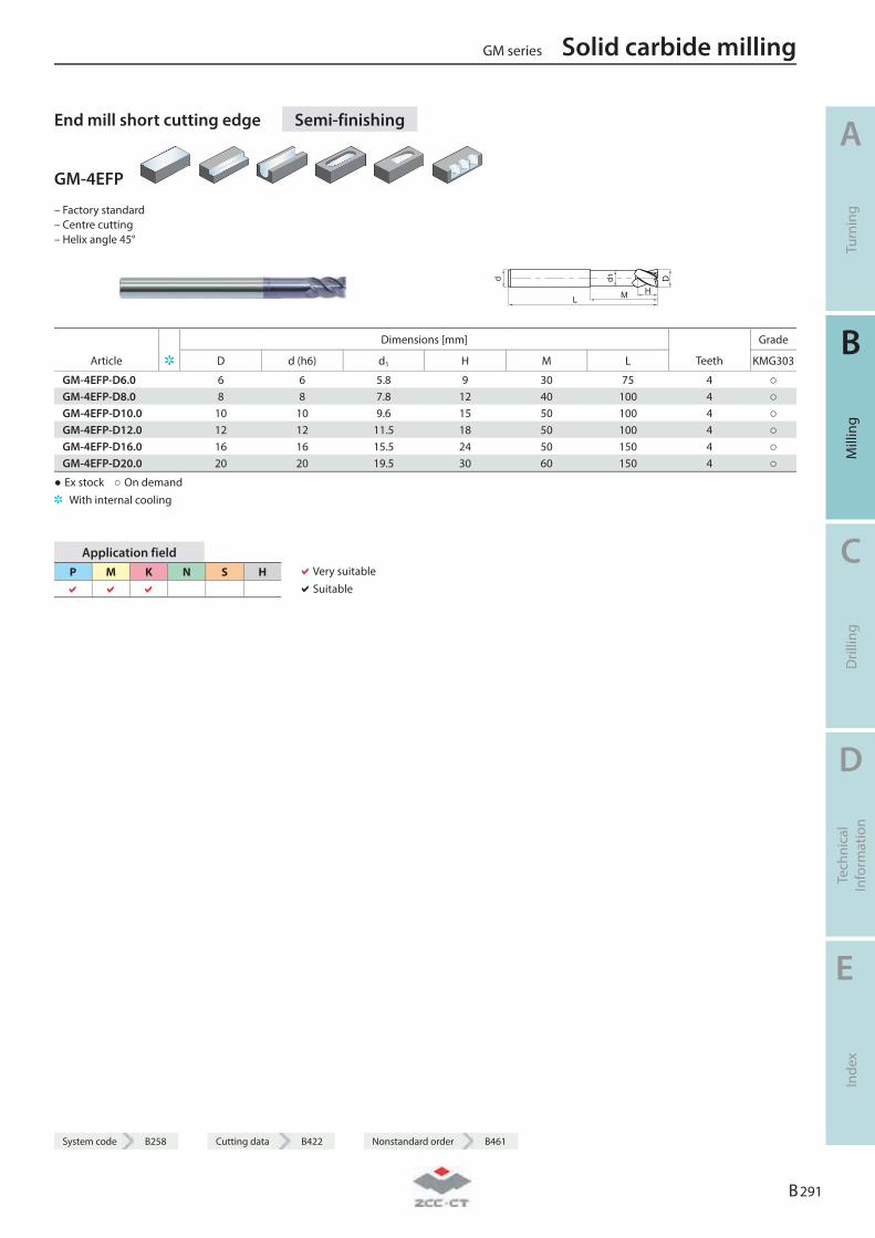
End mill short cutting edge Semi-finishing
GM-4EFP
– Factory standard – Centre cutting – Helix angle 45°
d
L
d1
HM
D
Dimensions [mm] Grade
Article D d (h6) d1 H M L Teeth KMG303
GM-4EFP-D6.0 6 6 5.8 9 30 75 4 ○ GM-4EFP-D8.0 8 8 7.8 12 40 100 4 ○ GM-4EFP-D10.0 10 10 9.6 15 50 100 4 ○ GM-4EFP-D12.0 12 12 11.5 18 50 100 4 ○ GM-4EFP-D16.0 16 16 15.5 24 50 150 4 ○ GM-4EFP-D20.0 20 20 19.5 30 60 150 4 ○
● Ex stock ○ On demand With internal cooling
Application field P M K N S H
Very suitable Suitable
GM series Solid carbide milling
A
Turn
ing
B
Mill
ing
C
Dril
ling
D
Tech
nica
l In
form
atio
n
E
Inde
x
B 291
System code B258 Cutting data B422 Nonstandard order B461
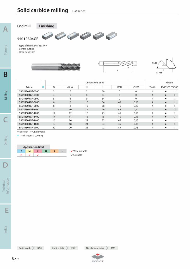
End mill Finishing
5501R304GF
– Type of shank DIN 6535HA – Centre cutting – Helix angle 30°
LH
Dd
KCH
CHW
Dimensions [mm] Grade
Article D d (h6) H L KCH CHW Teeth KMG303 YK30F
5501R304GF-0300 3 6 5 50 0 0 4 ● ○ 5501R304GF-0400 4 6 8 54 0 0 4 ● ○ 5501R304GF-0500 5 6 9 54 0 0 4 ● ○ 5501R304GF-0600 6 6 10 54 45 0,10 4 ● ○ 5501R304GF-0800 8 8 12 58 45 0,10 4 ● ○ 5501R304GF-1000 10 10 14 66 45 0,10 4 ● ○ 5501R304GF-1200 12 12 16 73 45 0,10 4 ● ○ 5501R304GF-1400 14 14 18 75 45 0,15 4 ● ○ 5501R304GF-1600 16 16 22 82 45 0,15 4 ● ○ 5501R304GF-1800 18 18 24 84 45 0,15 4 ● ○ 5501R304GF-2000 20 20 26 92 45 0,15 4 ● ○
● Ex stock ○ On demand With internal cooling
Application field P M K N S H
Very suitable Suitable
Solid carbide milling GM series
A
Turn
ing
B
Mill
ing
C
Dril
ling
D
Tech
nica
l In
form
atio
n
E
Inde
x
B 292
System code B258 Cutting data B422 Nonstandard order B461

System code B258 Cutting data B422 Nonstandard order B461
End mill Finishing
5601R304GF
– Type of shank: DIN 6535HB – Centre cutting – Helix angle 30°
LH
Dd
KCH
CHW
Dimensions [mm] Grade
Article D d (h6) H L KCH CHW Teeth KMG303 YK30F
5601R304GF-0300 3 6 5 50 0 0 4 ● ○ 5601R304GF-0400 4 6 8 54 0 0 4 ● ○ 5601R304GF-0500 5 6 9 54 0 0 4 ● ○ 5601R304GF-0600 6 6 10 54 45 0,10 4 ● ○ 5601R304GF-0800 8 8 12 58 45 0,10 4 ● ○ 5601R304GF-1000 10 10 14 66 45 0,10 4 ● ○ 5601R304GF-1200 12 12 16 73 45 0,10 4 ● ● 5601R304GF-1400 14 14 18 75 45 0,15 4 ● 5601R304GF-1600 16 16 22 82 45 0,15 4 ● ○ 5601R304GF-1800 18 18 24 84 45 0,15 4 ● ○ 5601R304GF-2000 20 20 26 92 45 0,15 4 ● ○
● Ex stock ○ On demand With internal cooling
Application field P M K N S H
Very suitable Suitable
GM series Solid carbide milling
A
Turn
ing
B
Mill
ing
C
Dril
ling
D
Tech
nica
l In
form
atio
n
E
Inde
x
B 293
System code B258 Cutting data B422 Nonstandard order B461

End mill long cutting edge Finishing
5502R304GF
– Type of shank DIN 6535HA – Centre cutting – Helix angle 30°
LH
Dd
KCH
CHW
Dimensions [mm] Grade
Article D d (h6) H L KCH CHW Teeth KMG303 YK30F
5502R304GF-0300 3 6 8 57 0 0 4 ● ○ 5502R304GF-0400 4 6 11 57 0 0 4 ● ○ 5502R304GF-0500 5 6 13 57 0 0 4 ● ○ 5502R304GF-0600 6 6 13 57 45 0,10 4 ● ○ 5502R304GF-0800 8 8 19 63 45 0,10 4 ● ○ 5502R304GF-1000 10 10 22 72 45 0,10 4 ● ○ 5502R304GF-1200 12 12 26 83 45 0,10 4 ● ○ 5502R304GF-1400 14 14 26 83 45 0,15 4 ● ○ 5502R304GF-1600 16 16 32 92 45 0,15 4 ● ○ 5502R304GF-1800 18 18 32 92 45 0,15 4 ● ○ 5502R304GF-2000 20 20 38 104 45 0,15 4 ● ○
● Ex stock ○ On demand With internal cooling
Application field P M K N S H
Very suitable Suitable
Solid carbide milling GM series
A
Turn
ing
B
Mill
ing
C
Dril
ling
D
Tech
nica
l In
form
atio
n
E
Inde
x
B 294
System code B258 Cutting data B422 Nonstandard order B461
System code B258 Cutting data B422 Nonstandard order B461
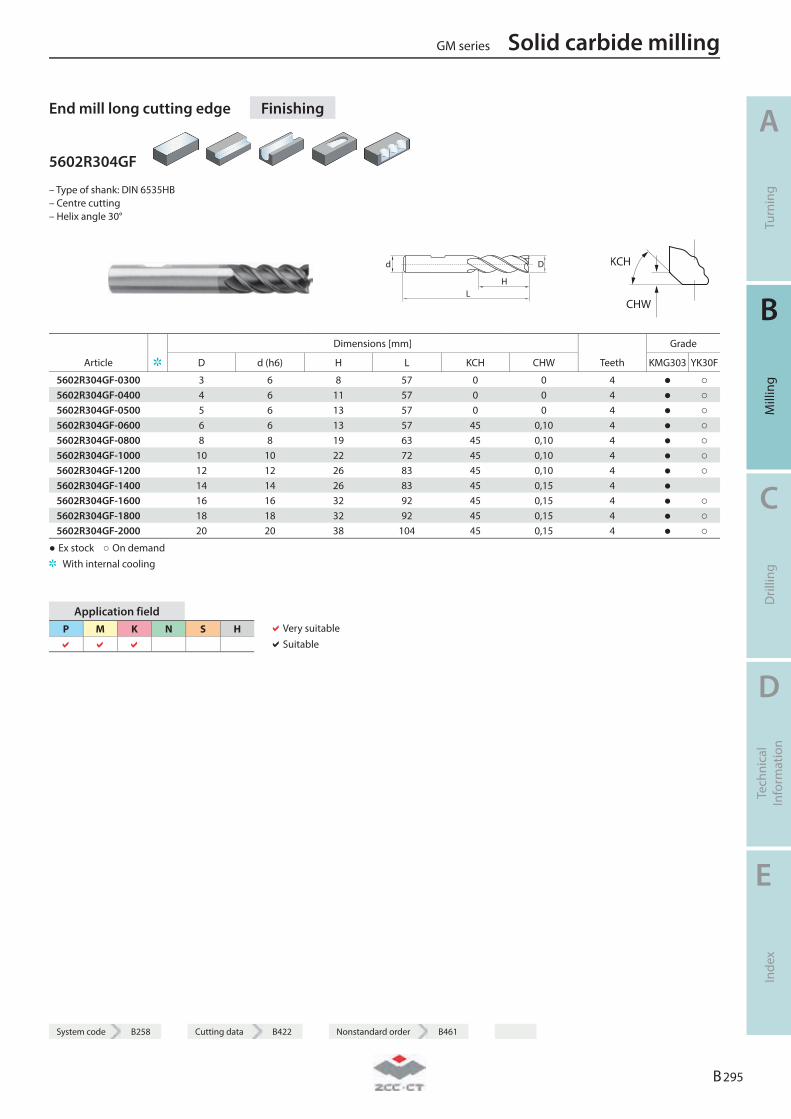
End mill long cutting edge Finishing
5602R304GF
– Type of shank: DIN 6535HB – Centre cutting – Helix angle 30°
LH
Dd
KCH
CHW
Dimensions [mm] Grade
Article D d (h6) H L KCH CHW Teeth KMG303 YK30F
5602R304GF-0300 3 6 8 57 0 0 4 ● ○ 5602R304GF-0400 4 6 11 57 0 0 4 ● ○ 5602R304GF-0500 5 6 13 57 0 0 4 ● ○ 5602R304GF-0600 6 6 13 57 45 0,10 4 ● ○ 5602R304GF-0800 8 8 19 63 45 0,10 4 ● ○ 5602R304GF-1000 10 10 22 72 45 0,10 4 ● ○ 5602R304GF-1200 12 12 26 83 45 0,10 4 ● ○ 5602R304GF-1400 14 14 26 83 45 0,15 4 ● 5602R304GF-1600 16 16 32 92 45 0,15 4 ● ○ 5602R304GF-1800 18 18 32 92 45 0,15 4 ● ○ 5602R304GF-2000 20 20 38 104 45 0,15 4 ● ○
● Ex stock ○ On demand With internal cooling
Application field P M K N S H
Very suitable Suitable
GM series Solid carbide milling
A
Turn
ing
B
Mill
ing
C
Dril
ling
D
Tech
nica
l In
form
atio
n
E
Inde
x
B 295
System code B258 Cutting data B422 Nonstandard order B461
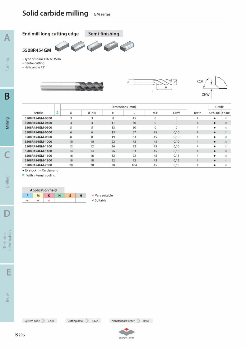
End mill long cutting edge Semi-finishing
5508R454GM
– Type of shank DIN 6535HA – Centre cutting – Helix angle 45°
LH
Dd
KCH
CHW
Dimensions [mm] Grade
Article D d (h6) H L KCH CHW Teeth KMG303 YK30F
5508R454GM-0300 3 3 8 45 0 0 4 ● ○ 5508R454GM-0400 4 4 11 50 0 0 4 ● ○ 5508R454GM-0500 5 5 13 50 0 0 4 ● ○ 5508R454GM-0600 6 6 13 57 45 0,10 4 ● ○ 5508R454GM-0800 8 8 19 63 45 0,10 4 ● ○ 5508R454GM-1000 10 10 22 72 45 0,10 4 ● ○ 5508R454GM-1200 12 12 26 83 45 0,10 4 ● ○ 5508R454GM-1400 14 14 26 83 45 0,15 4 ● ○ 5508R454GM-1600 16 16 32 92 45 0,15 4 ● ○ 5508R454GM-1800 18 18 32 92 45 0,15 4 ● ○ 5508R454GM-2000 20 20 38 104 45 0,15 4 ● ○
● Ex stock ○ On demand With internal cooling
Application field P M K N S H
Very suitable Suitable
Solid carbide milling GM series
A
Turn
ing
B
Mill
ing
C
Dril
ling
D
Tech
nica
l In
form
atio
n
E
Inde
x
B 296
System code B258 Cutting data B422 Nonstandard order B461
System code B258 Cutting data B422 Nonstandard order B461
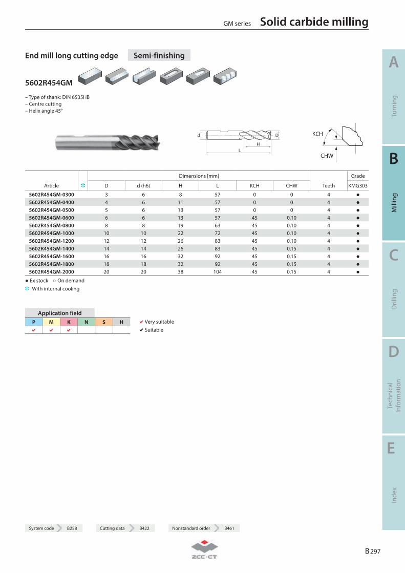
End mill long cutting edge Semi-finishing
5602R454GM
– Type of shank: DIN 6535HB – Centre cutting – Helix angle 45°
LH
Dd
KCH
CHW
Dimensions [mm] Grade
Article D d (h6) H L KCH CHW Teeth KMG303
5602R454GM-0300 3 6 8 57 0 0 4 ● 5602R454GM-0400 4 6 11 57 0 0 4 ● 5602R454GM-0500 5 6 13 57 0 0 4 ● 5602R454GM-0600 6 6 13 57 45 0,10 4 ● 5602R454GM-0800 8 8 19 63 45 0,10 4 ● 5602R454GM-1000 10 10 22 72 45 0,10 4 ● 5602R454GM-1200 12 12 26 83 45 0,10 4 ● 5602R454GM-1400 14 14 26 83 45 0,15 4 ● 5602R454GM-1600 16 16 32 92 45 0,15 4 ● 5602R454GM-1800 18 18 32 92 45 0,15 4 ● 5602R454GM-2000 20 20 38 104 45 0,15 4 ●
● Ex stock ○ On demand With internal cooling
Application field P M K N S H
Very suitable Suitable
GM series Solid carbide milling
A
Turn
ing
B
Mill
ing
C
Dril
ling
D
Tech
nica
l In
form
atio
n
E
Inde
x
B 297
System code B258 Cutting data B422 Nonstandard order B461
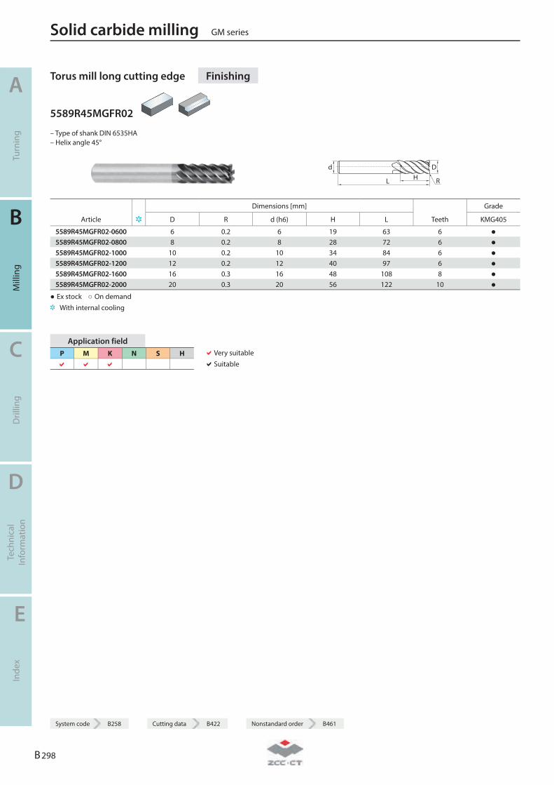
Torus mill long cutting edge Finishing
5589R45MGFR02
– Type of shank DIN 6535HA – Helix angle 45°
L HDd
R
Dimensions [mm] Grade
Article D R d (h6) H L Teeth KMG405
5589R45MGFR02-0600 6 0.2 6 19 63 6 ● 5589R45MGFR02-0800 8 0.2 8 28 72 6 ● 5589R45MGFR02-1000 10 0.2 10 34 84 6 ● 5589R45MGFR02-1200 12 0.2 12 40 97 6 ● 5589R45MGFR02-1600 16 0.3 16 48 108 8 ● 5589R45MGFR02-2000 20 0.3 20 56 122 10 ●
● Ex stock ○ On demand With internal cooling
Application field P M K N S H
Very suitable Suitable
Solid carbide milling GM series
A
Turn
ing
B
Mill
ing
C
Dril
ling
D
Tech
nica
l In
form
atio
n
E
Inde
x
B 298
System code B258 Cutting data B422 Nonstandard order B461
System code B258 Cutting data B422 Nonstandard order B461
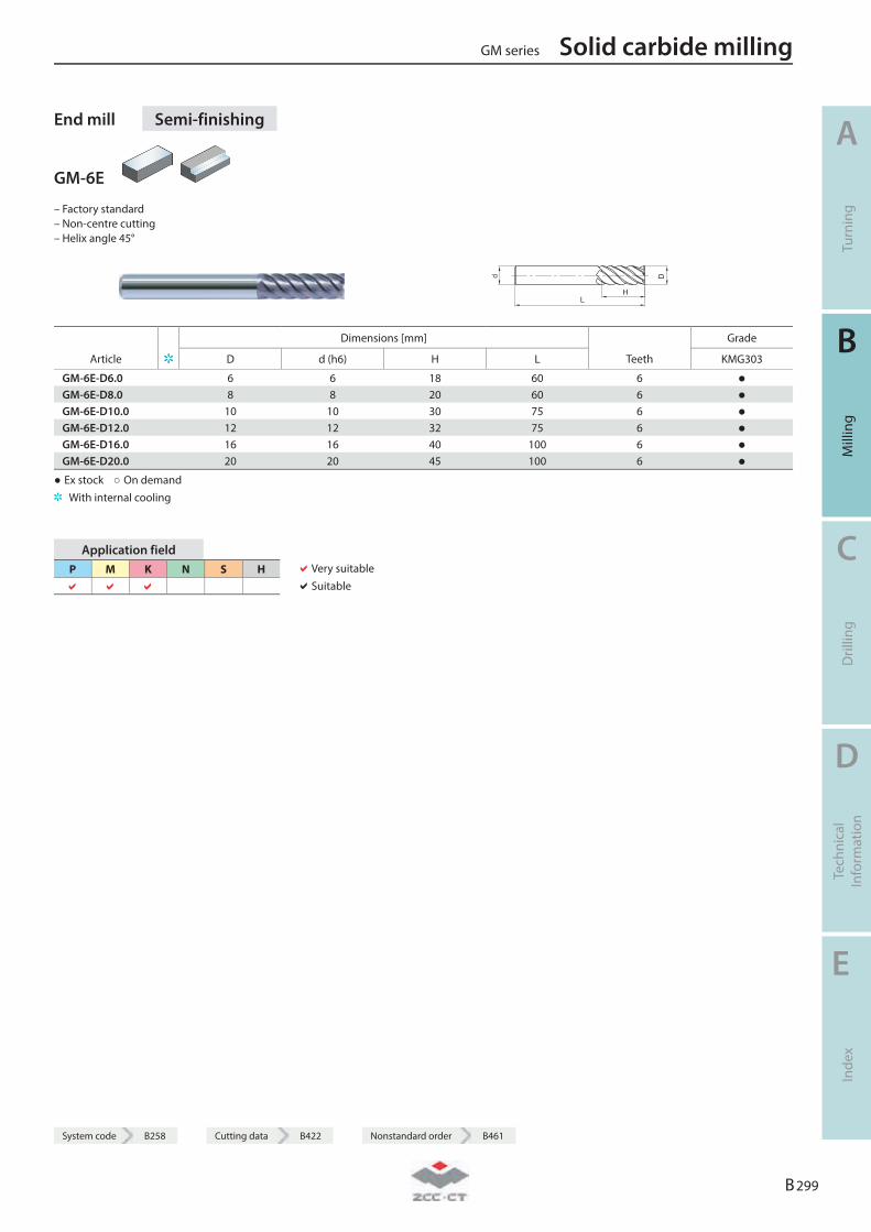
End mill Semi-finishing
GM-6E
– Factory standard – Non-centre cutting – Helix angle 45°
L
D
H
d
Dimensions [mm] Grade
Article D d (h6) H L Teeth KMG303
GM-6E-D6.0 6 6 18 60 6 ● GM-6E-D8.0 8 8 20 60 6 ● GM-6E-D10.0 10 10 30 75 6 ● GM-6E-D12.0 12 12 32 75 6 ● GM-6E-D16.0 16 16 40 100 6 ● GM-6E-D20.0 20 20 45 100 6 ●
● Ex stock ○ On demand With internal cooling
Application field P M K N S H
Very suitable Suitable
GM series Solid carbide milling
A
Turn
ing
B
Mill
ing
C
Dril
ling
D
Tech
nica
l In
form
atio
n
E
Inde
x
B 299
System code B258 Cutting data B422 Nonstandard order B461
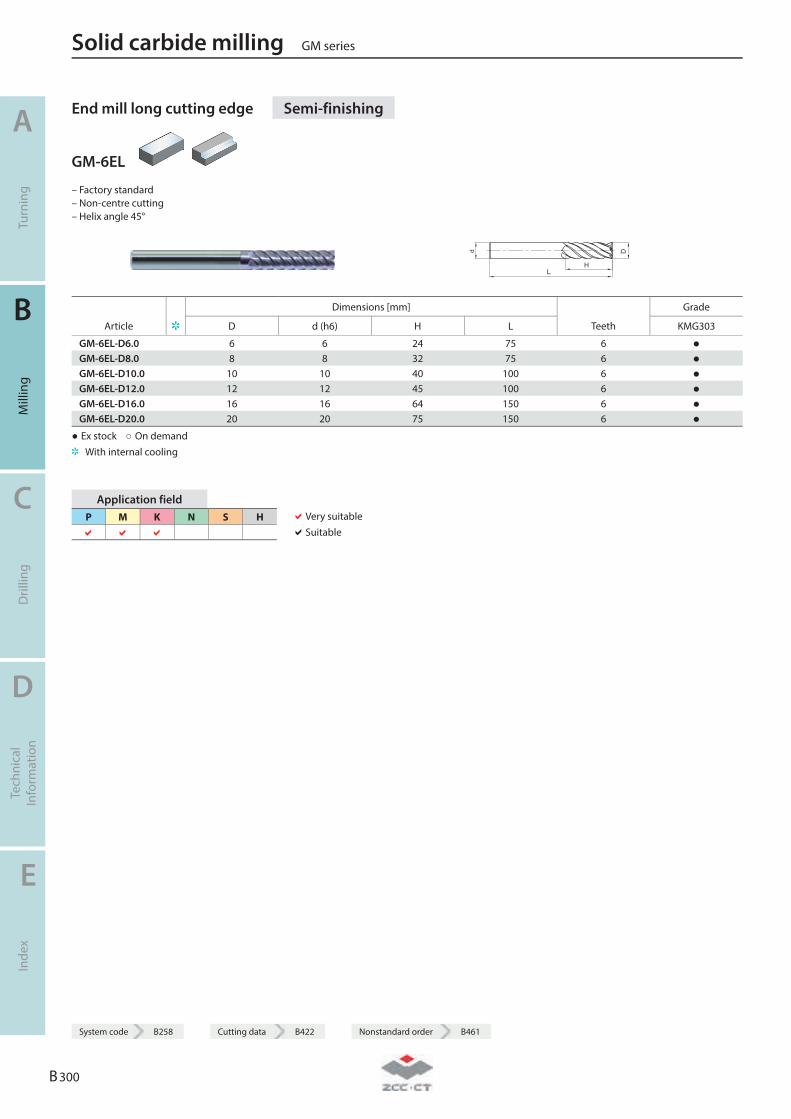
End mill long cutting edge Semi-finishing
GM-6EL
– Factory standard – Non-centre cutting – Helix angle 45°
L
D
H
d
Dimensions [mm] Grade
Article D d (h6) H L Teeth KMG303
GM-6EL-D6.0 6 6 24 75 6 ● GM-6EL-D8.0 8 8 32 75 6 ● GM-6EL-D10.0 10 10 40 100 6 ● GM-6EL-D12.0 12 12 45 100 6 ● GM-6EL-D16.0 16 16 64 150 6 ● GM-6EL-D20.0 20 20 75 150 6 ●
● Ex stock ○ On demand With internal cooling
Application field P M K N S H
Very suitable Suitable
Solid carbide milling GM series
A
Turn
ing
B
Mill
ing
C
Dril
ling
D
Tech
nica
l In
form
atio
n
E
Inde
x
B 300
System code B258 Cutting data B422 Nonstandard order B461
System code B258 Cutting data B422 Nonstandard order B461
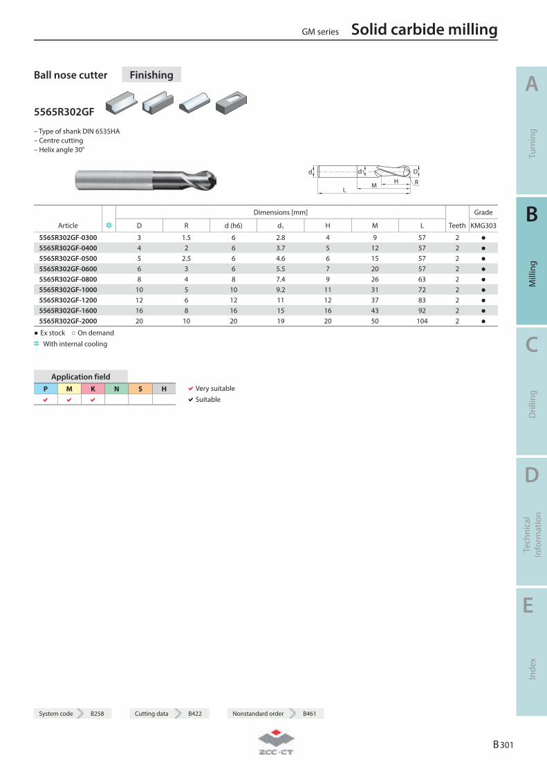
Ball nose cutter Finishing
5565R302GF
– Type of shank DIN 6535HA – Centre cutting – Helix angle 30°
LM
HDd d1
R
Dimensions [mm] Grade
Article D R d (h6) d1 H M L Teeth KMG303
5565R302GF-0300 3 1.5 6 2.8 4 9 57 2 ● 5565R302GF-0400 4 2 6 3.7 5 12 57 2 ● 5565R302GF-0500 5 2.5 6 4.6 6 15 57 2 ● 5565R302GF-0600 6 3 6 5.5 7 20 57 2 ● 5565R302GF-0800 8 4 8 7.4 9 26 63 2 ● 5565R302GF-1000 10 5 10 9.2 11 31 72 2 ● 5565R302GF-1200 12 6 12 11 12 37 83 2 ● 5565R302GF-1600 16 8 16 15 16 43 92 2 ● 5565R302GF-2000 20 10 20 19 20 50 104 2 ●
● Ex stock ○ On demand With internal cooling
Application field P M K N S H
Very suitable Suitable
GM series Solid carbide milling
A
Turn
ing
B
Mill
ing
C
Dril
ling
D
Tech
nica
l In
form
atio
n
E
Inde
x
B 301
System code B258 Cutting data B422 Nonstandard order B461
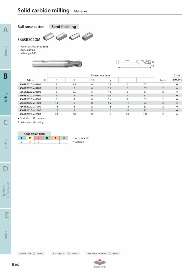
Ball nose cutter Semi-finishing
5665R202GM
– Type of shank: DIN 6535HB – Centre cutting – Helix angle 20°
L HDd
R
Dimensions [mm] Grade
Article D R d (h6) d1 H L Teeth KMG303
5665R202GM-0300 3 1.5 6 2.8 4 57 2 ● 5665R202GM-0400 4 2 6 3.7 5 57 2 ● 5665R202GM-0500 5 2.5 6 4.6 6 57 2 ● 5665R202GM-0600 6 3 6 5.5 7 57 2 ● 5665R202GM-0800 8 4 8 7.4 9 63 2 ● 5665R202GM-1000 10 5 10 9.2 11 72 2 ● 5665R202GM-1200 12 6 12 11 12 83 2 ● 5665R202GM-1600 16 8 16 15 16 92 2 ● 5665R202GM-2000 20 10 20 19 20 104 2 ●
● Ex stock ○ On demand With internal cooling
Application field P M K N S H
Very suitable Suitable
Solid carbide milling GM series
A
Turn
ing
B
Mill
ing
C
Dril
ling
D
Tech
nica
l In
form
atio
n
E
Inde
x
B 302
System code B258 Cutting data B422 Nonstandard order B461
System code B258 Cutting data B422 Nonstandard order B461
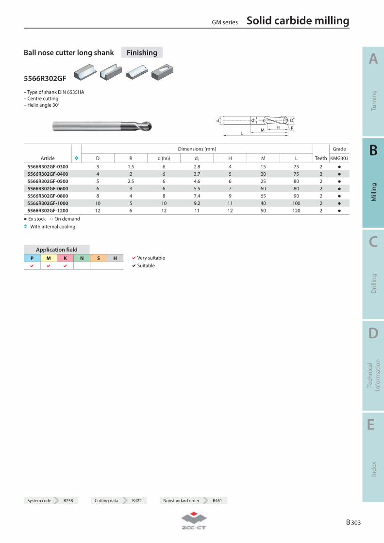
Ball nose cutter long shank Finishing
5566R302GF
– Type of shank DIN 6535HA – Centre cutting – Helix angle 30°
LM
HDd d1
R
Dimensions [mm] Grade
Article D R d (h6) d1 H M L Teeth KMG303
5566R302GF-0300 3 1.5 6 2.8 4 15 75 2 ● 5566R302GF-0400 4 2 6 3.7 5 20 75 2 ● 5566R302GF-0500 5 2.5 6 4.6 6 25 80 2 ● 5566R302GF-0600 6 3 6 5.5 7 60 80 2 ● 5566R302GF-0800 8 4 8 7.4 9 65 90 2 ● 5566R302GF-1000 10 5 10 9.2 11 40 100 2 ● 5566R302GF-1200 12 6 12 11 12 50 120 2 ●
● Ex stock ○ On demand With internal cooling
Application field P M K N S H
Very suitable Suitable
GM series Solid carbide milling
A
Turn
ing
B
Mill
ing
C
Dril
ling
D
Tech
nica
l In
form
atio
n
E
Inde
x
B 303
System code B258 Cutting data B422 Nonstandard order B461
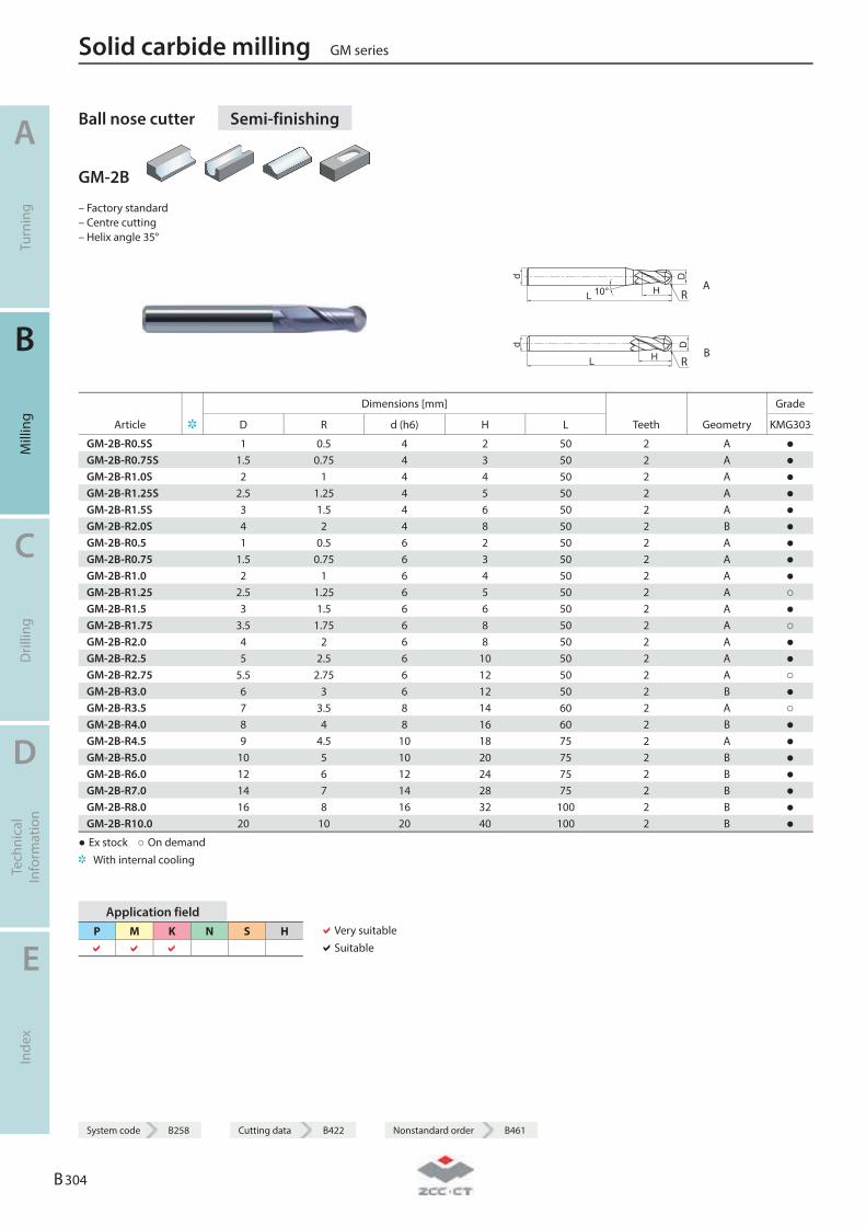
Ball nose cutter Semi-finishing
GM-2B
– Factory standard – Centre cutting – Helix angle 35°
R A
R B
Dimensions [mm] Grade
Article D R d (h6) H L Teeth Geometry KMG303
GM-2B-R0.5S 1 0.5 4 2 50 2 A ● GM-2B-R0.75S 1.5 0.75 4 3 50 2 A ● GM-2B-R1.0S 2 1 4 4 50 2 A ● GM-2B-R1.25S 2.5 1.25 4 5 50 2 A ● GM-2B-R1.5S 3 1.5 4 6 50 2 A ● GM-2B-R2.0S 4 2 4 8 50 2 B ● GM-2B-R0.5 1 0.5 6 2 50 2 A ● GM-2B-R0.75 1.5 0.75 6 3 50 2 A ● GM-2B-R1.0 2 1 6 4 50 2 A ● GM-2B-R1.25 2.5 1.25 6 5 50 2 A ○ GM-2B-R1.5 3 1.5 6 6 50 2 A ● GM-2B-R1.75 3.5 1.75 6 8 50 2 A ○ GM-2B-R2.0 4 2 6 8 50 2 A ● GM-2B-R2.5 5 2.5 6 10 50 2 A ● GM-2B-R2.75 5.5 2.75 6 12 50 2 A ○ GM-2B-R3.0 6 3 6 12 50 2 B ● GM-2B-R3.5 7 3.5 8 14 60 2 A ○ GM-2B-R4.0 8 4 8 16 60 2 B ● GM-2B-R4.5 9 4.5 10 18 75 2 A ● GM-2B-R5.0 10 5 10 20 75 2 B ● GM-2B-R6.0 12 6 12 24 75 2 B ● GM-2B-R7.0 14 7 14 28 75 2 B ● GM-2B-R8.0 16 8 16 32 100 2 B ● GM-2B-R10.0 20 10 20 40 100 2 B ●
● Ex stock ○ On demand With internal cooling
Application field P M K N S H
Very suitable Suitable
Solid carbide milling GM series
A
Turn
ing
B
Mill
ing
C
Dril
ling
D
Tech
nica
l In
form
atio
n
E
Inde
x
B 304
System code B258 Cutting data B422 Nonstandard order B461
System code B258 Cutting data B422 Nonstandard order B461
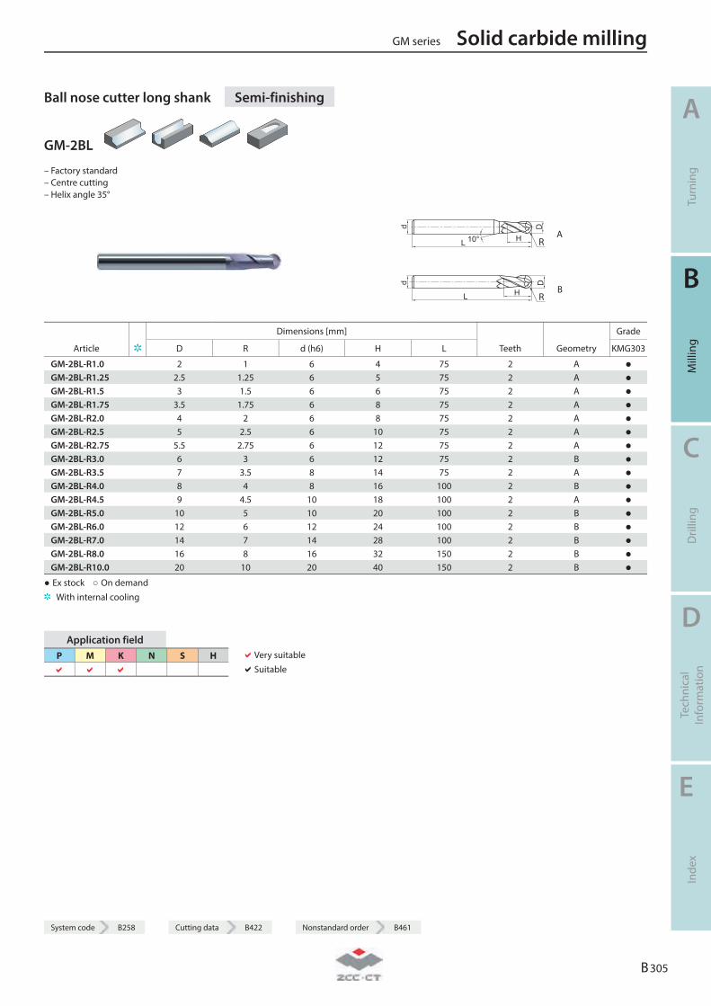
Ball nose cutter long shank Semi-finishing
GM-2BL
– Factory standard – Centre cutting – Helix angle 35°
R A
R B
Dimensions [mm] Grade
Article D R d (h6) H L Teeth Geometry KMG303
GM-2BL-R1.0 2 1 6 4 75 2 A ● GM-2BL-R1.25 2.5 1.25 6 5 75 2 A ● GM-2BL-R1.5 3 1.5 6 6 75 2 A ● GM-2BL-R1.75 3.5 1.75 6 8 75 2 A ● GM-2BL-R2.0 4 2 6 8 75 2 A ● GM-2BL-R2.5 5 2.5 6 10 75 2 A ● GM-2BL-R2.75 5.5 2.75 6 12 75 2 A ● GM-2BL-R3.0 6 3 6 12 75 2 B ● GM-2BL-R3.5 7 3.5 8 14 75 2 A ● GM-2BL-R4.0 8 4 8 16 100 2 B ● GM-2BL-R4.5 9 4.5 10 18 100 2 A ● GM-2BL-R5.0 10 5 10 20 100 2 B ● GM-2BL-R6.0 12 6 12 24 100 2 B ● GM-2BL-R7.0 14 7 14 28 100 2 B ● GM-2BL-R8.0 16 8 16 32 150 2 B ● GM-2BL-R10.0 20 10 20 40 150 2 B ●
● Ex stock ○ On demand With internal cooling
Application field P M K N S H
Very suitable Suitable
GM series Solid carbide milling
A
Turn
ing
B
Mill
ing
C
Dril
ling
D
Tech
nica
l In
form
atio
n
E
Inde
x
B 305
System code B258 Cutting data B422 Nonstandard order B461
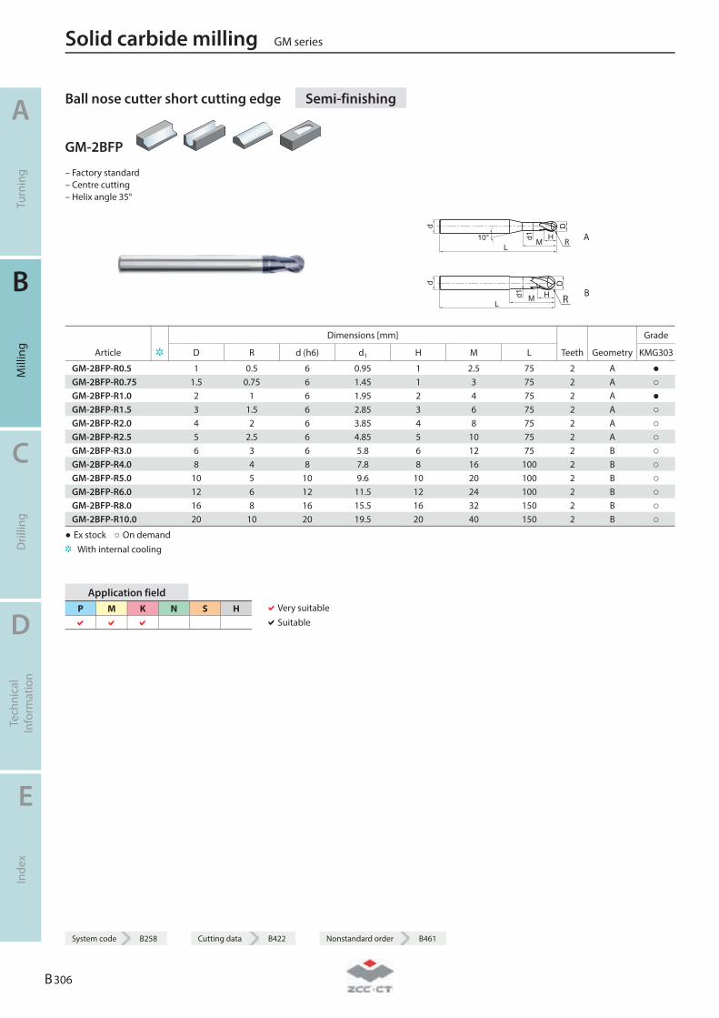
Ball nose cutter short cutting edge Semi-finishing
GM-2BFP
– Factory standard – Centre cutting – Helix angle 35°
d
L10° H
Md1
D
R A
d
LHMd1
D
R B
Dimensions [mm] Grade
Article D R d (h6) d1 H M L Teeth Geometry KMG303
GM-2BFP-R0.5 1 0.5 6 0.95 1 2.5 75 2 A ● GM-2BFP-R0.75 1.5 0.75 6 1.45 1 3 75 2 A ○ GM-2BFP-R1.0 2 1 6 1.95 2 4 75 2 A ● GM-2BFP-R1.5 3 1.5 6 2.85 3 6 75 2 A ○ GM-2BFP-R2.0 4 2 6 3.85 4 8 75 2 A ○ GM-2BFP-R2.5 5 2.5 6 4.85 5 10 75 2 A ○ GM-2BFP-R3.0 6 3 6 5.8 6 12 75 2 B ○ GM-2BFP-R4.0 8 4 8 7.8 8 16 100 2 B ○ GM-2BFP-R5.0 10 5 10 9.6 10 20 100 2 B ○ GM-2BFP-R6.0 12 6 12 11.5 12 24 100 2 B ○ GM-2BFP-R8.0 16 8 16 15.5 16 32 150 2 B ○ GM-2BFP-R10.0 20 10 20 19.5 20 40 150 2 B ○
● Ex stock ○ On demand With internal cooling
Application field P M K N S H
Very suitable Suitable
Solid carbide milling GM series
A
Turn
ing
B
Mill
ing
C
Dril
ling
D
Tech
nica
l In
form
atio
n
E
Inde
x
B 306
System code B258 Cutting data B422 Nonstandard order B461
System code B258 Cutting data B422 Nonstandard order B461
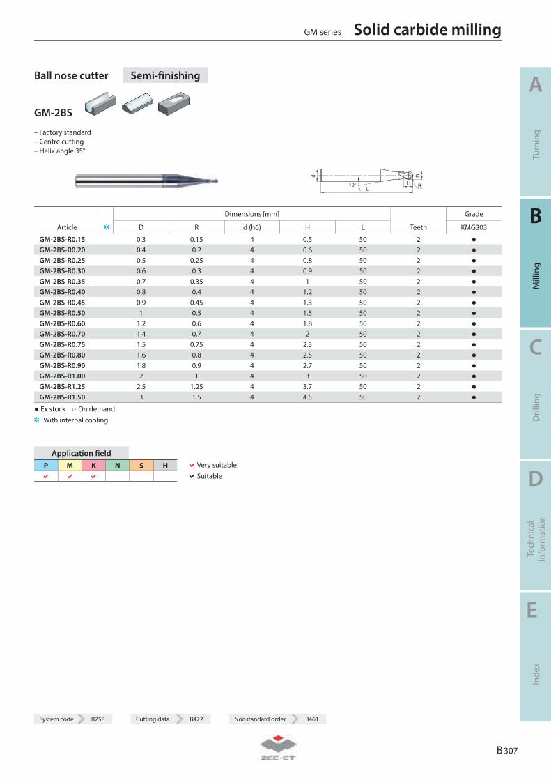
Ball nose cutter Semi-finishing
GM-2BS
– Factory standard – Centre cutting – Helix angle 35°
L
D
H
d
10° R
Dimensions [mm] Grade
Article D R d (h6) H L Teeth KMG303
GM-2BS-R0.15 0.3 0.15 4 0.5 50 2 ● GM-2BS-R0.20 0.4 0.2 4 0.6 50 2 ● GM-2BS-R0.25 0.5 0.25 4 0.8 50 2 ● GM-2BS-R0.30 0.6 0.3 4 0.9 50 2 ● GM-2BS-R0.35 0.7 0.35 4 1 50 2 ● GM-2BS-R0.40 0.8 0.4 4 1.2 50 2 ● GM-2BS-R0.45 0.9 0.45 4 1.3 50 2 ● GM-2BS-R0.50 1 0.5 4 1.5 50 2 ● GM-2BS-R0.60 1.2 0.6 4 1.8 50 2 ● GM-2BS-R0.70 1.4 0.7 4 2 50 2 ● GM-2BS-R0.75 1.5 0.75 4 2.3 50 2 ● GM-2BS-R0.80 1.6 0.8 4 2.5 50 2 ● GM-2BS-R0.90 1.8 0.9 4 2.7 50 2 ● GM-2BS-R1.00 2 1 4 3 50 2 ● GM-2BS-R1.25 2.5 1.25 4 3.7 50 2 ● GM-2BS-R1.50 3 1.5 4 4.5 50 2 ●
● Ex stock ○ On demand With internal cooling
Application field P M K N S H
Very suitable Suitable
GM series Solid carbide milling
A
Turn
ing
B
Mill
ing
C
Dril
ling
D
Tech
nica
l In
form
atio
n
E
Inde
x
B 307
System code B258 Cutting data B422 Nonstandard order B461
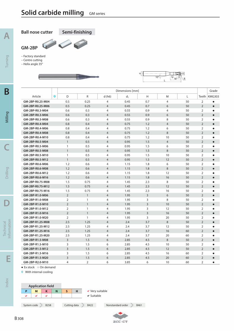
Ball nose cutter Semi-finishing
GM-2BP
– Factory standard – Centre cutting – Helix angle 35°
d
L10° H
Md1
D
R
Dimensions [mm] Grade
Article D R d (h6) d1 H M L Teeth KMG303
GM-2BP-R0.25-M04 0.5 0.25 4 0.45 0.7 4 50 2 ● GM-2BP-R0.25-M06 0.5 0.25 4 0.45 0.7 6 50 2 ● GM-2BP-R0.3-M04 0.6 0.3 4 0.55 0.9 4 50 2 ● GM-2BP-R0.3-M06 0.6 0.3 4 0.55 0.9 6 50 2 ● GM-2BP-R0.3-M08 0.6 0.3 4 0.55 0.9 8 50 2 ● GM-2BP-R0.4-M04 0.8 0.4 4 0.75 1.2 4 50 2 ● GM-2BP-R0.4-M06 0.8 0.4 4 0.75 1.2 6 50 2 ● GM-2BP-R0.4-M08 0.8 0.4 4 0.75 1.2 8 50 2 ● GM-2BP-R0.4-M10 0.8 0.4 4 0.75 1.2 10 50 2 ● GM-2BP-R0.5-M04 1 0.5 4 0.95 1.5 4 50 2 ● GM-2BP-R0.5-M06 1 0.5 4 0.95 1.5 6 50 2 ● GM-2BP-R0.5-M08 1 0.5 4 0.95 1.5 8 50 2 ● GM-2BP-R0.5-M10 1 0.5 4 0.95 1.5 10 50 2 ● GM-2BP-R0.5-M12 1 0.5 4 0.95 1.5 12 50 2 ● GM-2BP-R0.6-M06 1.2 0.6 4 1.15 1.8 6 50 2 ● GM-2BP-R0.6-M08 1.2 0.6 4 1.15 1.8 8 50 2 ● GM-2BP-R0.6-M12 1.2 0.6 4 1.15 1.8 12 50 2 ● GM-2BP-R0.6-M16 1.2 0.6 4 1.15 1.8 16 50 2 ● GM-2BP-R0.75-M08 1.5 0.75 4 1.45 2.3 8 50 2 ● GM-2BP-R0.75-M12 1.5 0.75 4 1.45 2.3 12 50 2 ● GM-2BP-R0.75-M16 1.5 0.75 4 1.45 2.3 16 50 2 ● GM-2BP-R1.0-M06 2 1 4 1.95 3 6 50 2 ● GM-2BP-R1.0-M08 2 1 4 1.95 3 8 50 2 ● GM-2BP-R1.0-M10 2 1 4 1.95 3 10 50 2 ● GM-2BP-R1.0-M12 2 1 4 1.95 3 12 50 2 ● GM-2BP-R1.0-M16 2 1 4 1.95 3 16 50 2 ● GM-2BP-R1.0-M20 2 1 4 1.95 3 20 50 2 ● GM-2BP-R1.25-M08 2.5 1.25 4 2.4 3.7 8 50 2 ● GM-2BP-R1.25-M12 2.5 1.25 4 2.4 3.7 12 50 2 ● GM-2BP-R1.25-M16 2.5 1.25 4 2.4 3.7 16 60 2 ● GM-2BP-R1.25-M20 2.5 1.25 4 2.4 3.7 20 60 2 ● GM-2BP-R1.5-M08 3 1.5 6 2.85 4.5 8 50 2 ● GM-2BP-R1.5-M10 3 1.5 6 2.85 4.5 10 50 2 ● GM-2BP-R1.5-M12 3 1.5 6 2.85 4.5 12 50 2 ● GM-2BP-R1.5-M16 3 1.5 6 2.85 4.5 16 60 2 ● GM-2BP-R1.5-M20 3 1.5 6 2.85 4.5 20 60 2 ● GM-2BP-R2.0-M10 4 2 6 3.85 6 10 60 2 ●
● Ex stock ○ On demand With internal cooling
Application field P M K N S H
Very suitable Suitable
Solid carbide milling GM series
A
Turn
ing
B
Mill
ing
C
Dril
ling
D
Tech
nica
l In
form
atio
n
E
Inde
x
B 308
System code B258 Cutting data B422 Nonstandard order B461
System code B258 Cutting data B422 Nonstandard order B461
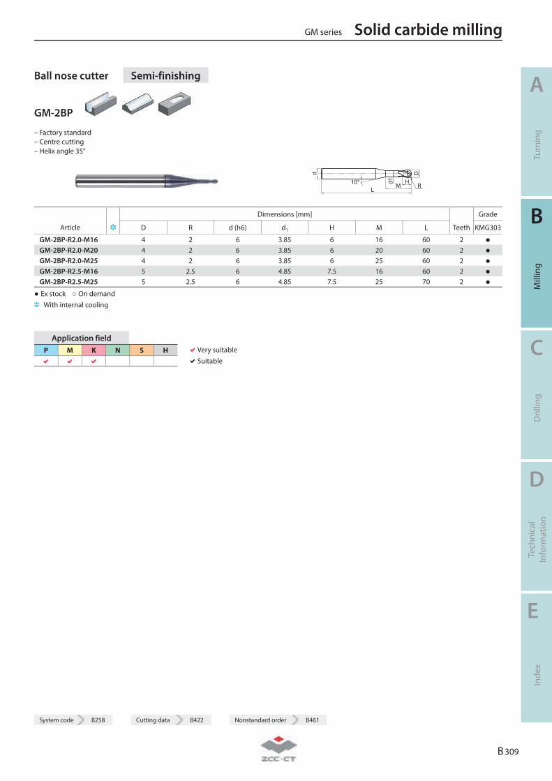
Ball nose cutter Semi-finishing
GM-2BP
– Factory standard – Centre cutting – Helix angle 35°
d
L10° H
Md1
D
R
Dimensions [mm] Grade
Article D R d (h6) d1 H M L Teeth KMG303
GM-2BP-R2.0-M16 4 2 6 3.85 6 16 60 2 ● GM-2BP-R2.0-M20 4 2 6 3.85 6 20 60 2 ● GM-2BP-R2.0-M25 4 2 6 3.85 6 25 60 2 ● GM-2BP-R2.5-M16 5 2.5 6 4.85 7.5 16 60 2 ● GM-2BP-R2.5-M25 5 2.5 6 4.85 7.5 25 70 2 ●
● Ex stock ○ On demand With internal cooling
Application field P M K N S H
Very suitable Suitable
GM series Solid carbide milling
A
Turn
ing
B
Mill
ing
C
Dril
ling
D
Tech
nica
l In
form
atio
n
E
Inde
x
B 309
System code B258 Cutting data B422 Nonstandard order B461
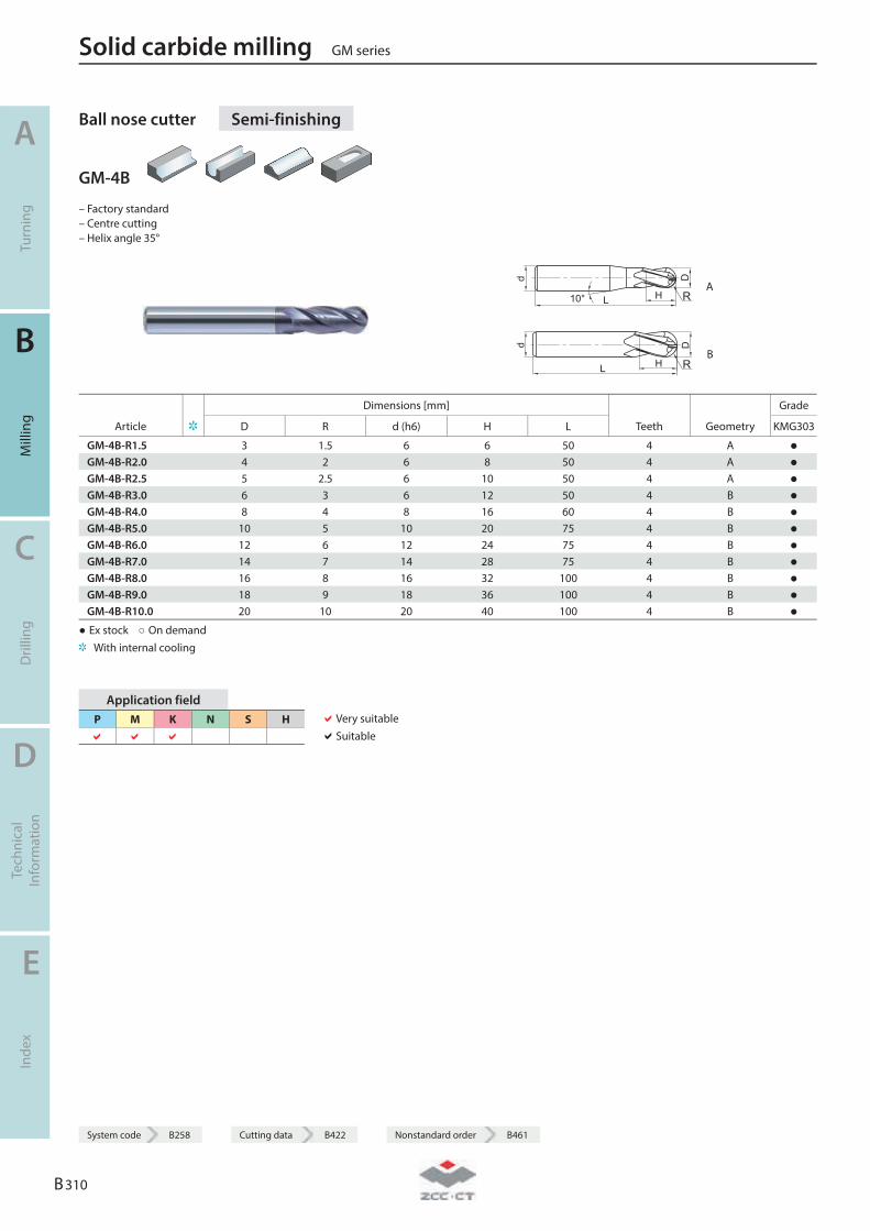
Ball nose cutter Semi-finishing
GM-4B
– Factory standard – Centre cutting – Helix angle 35°
d
L H
D
10° R A
d
L H
D
R B
Dimensions [mm] Grade
Article D R d (h6) H L Teeth Geometry KMG303
GM-4B-R1.5 3 1.5 6 6 50 4 A ● GM-4B-R2.0 4 2 6 8 50 4 A ● GM-4B-R2.5 5 2.5 6 10 50 4 A ● GM-4B-R3.0 6 3 6 12 50 4 B ● GM-4B-R4.0 8 4 8 16 60 4 B ● GM-4B-R5.0 10 5 10 20 75 4 B ● GM-4B-R6.0 12 6 12 24 75 4 B ● GM-4B-R7.0 14 7 14 28 75 4 B ● GM-4B-R8.0 16 8 16 32 100 4 B ● GM-4B-R9.0 18 9 18 36 100 4 B ● GM-4B-R10.0 20 10 20 40 100 4 B ●
● Ex stock ○ On demand With internal cooling
Application field P M K N S H
Very suitable Suitable
Solid carbide milling GM series
A
Turn
ing
B
Mill
ing
C
Dril
ling
D
Tech
nica
l In
form
atio
n
E
Inde
x
B 310
System code B258 Cutting data B422 Nonstandard order B461
System code B258 Cutting data B422 Nonstandard order B461
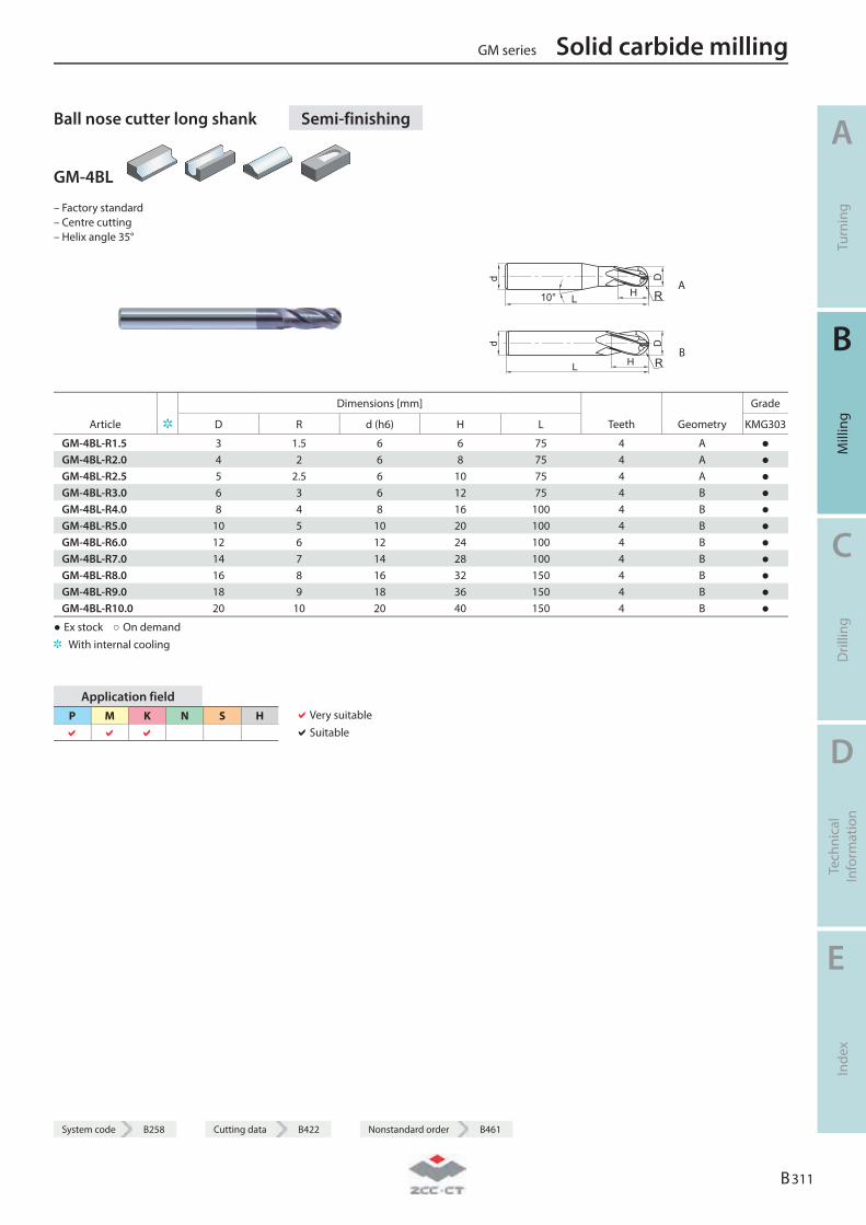
Ball nose cutter long shank Semi-finishing
GM-4BL
– Factory standard – Centre cutting – Helix angle 35°
d
L H
D
10° R A
d
L H
D
R B
Dimensions [mm] Grade
Article D R d (h6) H L Teeth Geometry KMG303
GM-4BL-R1.5 3 1.5 6 6 75 4 A ● GM-4BL-R2.0 4 2 6 8 75 4 A ● GM-4BL-R2.5 5 2.5 6 10 75 4 A ● GM-4BL-R3.0 6 3 6 12 75 4 B ● GM-4BL-R4.0 8 4 8 16 100 4 B ● GM-4BL-R5.0 10 5 10 20 100 4 B ● GM-4BL-R6.0 12 6 12 24 100 4 B ● GM-4BL-R7.0 14 7 14 28 100 4 B ● GM-4BL-R8.0 16 8 16 32 150 4 B ● GM-4BL-R9.0 18 9 18 36 150 4 B ● GM-4BL-R10.0 20 10 20 40 150 4 B ●
● Ex stock ○ On demand With internal cooling
Application field P M K N S H
Very suitable Suitable
GM series Solid carbide milling
A
Turn
ing
B
Mill
ing
C
Dril
ling
D
Tech
nica
l In
form
atio
n
E
Inde
x
B 311
System code B258 Cutting data B422 Nonstandard order B461
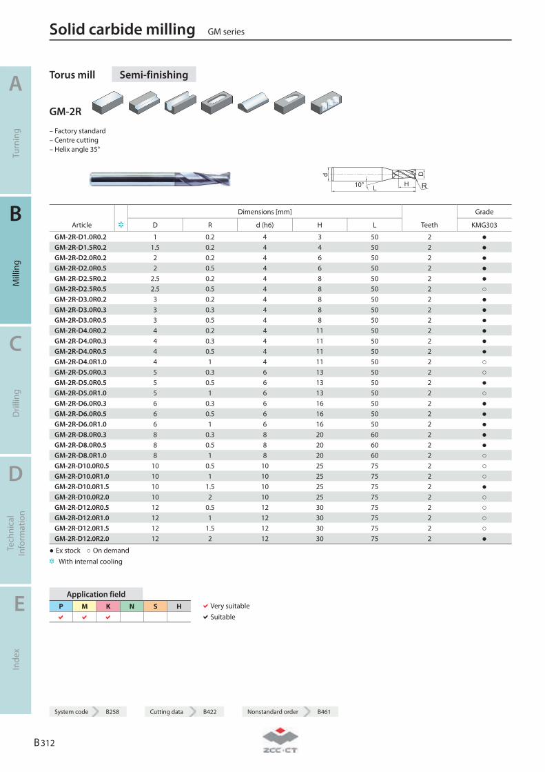
Torus mill Semi-finishing
GM-2R
– Factory standard – Centre cutting – Helix angle 35°
R
Dimensions [mm] Grade
Article D R d (h6) H L Teeth KMG303
GM-2R-D1.0R0.2 1 0.2 4 3 50 2 ● GM-2R-D1.5R0.2 1.5 0.2 4 4 50 2 ● GM-2R-D2.0R0.2 2 0.2 4 6 50 2 ● GM-2R-D2.0R0.5 2 0.5 4 6 50 2 ● GM-2R-D2.5R0.2 2.5 0.2 4 8 50 2 ● GM-2R-D2.5R0.5 2.5 0.5 4 8 50 2 ○ GM-2R-D3.0R0.2 3 0.2 4 8 50 2 ● GM-2R-D3.0R0.3 3 0.3 4 8 50 2 ● GM-2R-D3.0R0.5 3 0.5 4 8 50 2 ● GM-2R-D4.0R0.2 4 0.2 4 11 50 2 ● GM-2R-D4.0R0.3 4 0.3 4 11 50 2 ● GM-2R-D4.0R0.5 4 0.5 4 11 50 2 ● GM-2R-D4.0R1.0 4 1 4 11 50 2 ○ GM-2R-D5.0R0.3 5 0.3 6 13 50 2 ○ GM-2R-D5.0R0.5 5 0.5 6 13 50 2 ● GM-2R-D5.0R1.0 5 1 6 13 50 2 ○ GM-2R-D6.0R0.3 6 0.3 6 16 50 2 ● GM-2R-D6.0R0.5 6 0.5 6 16 50 2 ● GM-2R-D6.0R1.0 6 1 6 16 50 2 ● GM-2R-D8.0R0.3 8 0.3 8 20 60 2 ● GM-2R-D8.0R0.5 8 0.5 8 20 60 2 ● GM-2R-D8.0R1.0 8 1 8 20 60 2 ○ GM-2R-D10.0R0.5 10 0.5 10 25 75 2 ○ GM-2R-D10.0R1.0 10 1 10 25 75 2 ○ GM-2R-D10.0R1.5 10 1.5 10 25 75 2 ● GM-2R-D10.0R2.0 10 2 10 25 75 2 ○ GM-2R-D12.0R0.5 12 0.5 12 30 75 2 ○ GM-2R-D12.0R1.0 12 1 12 30 75 2 ○ GM-2R-D12.0R1.5 12 1.5 12 30 75 2 ○ GM-2R-D12.0R2.0 12 2 12 30 75 2 ●
● Ex stock ○ On demand With internal cooling
Application field P M K N S H
Very suitable Suitable
Solid carbide milling GM series
A
Turn
ing
B
Mill
ing
C
Dril
ling
D
Tech
nica
l In
form
atio
n
E
Inde
x
B 312
System code B258 Cutting data B422 Nonstandard order B461
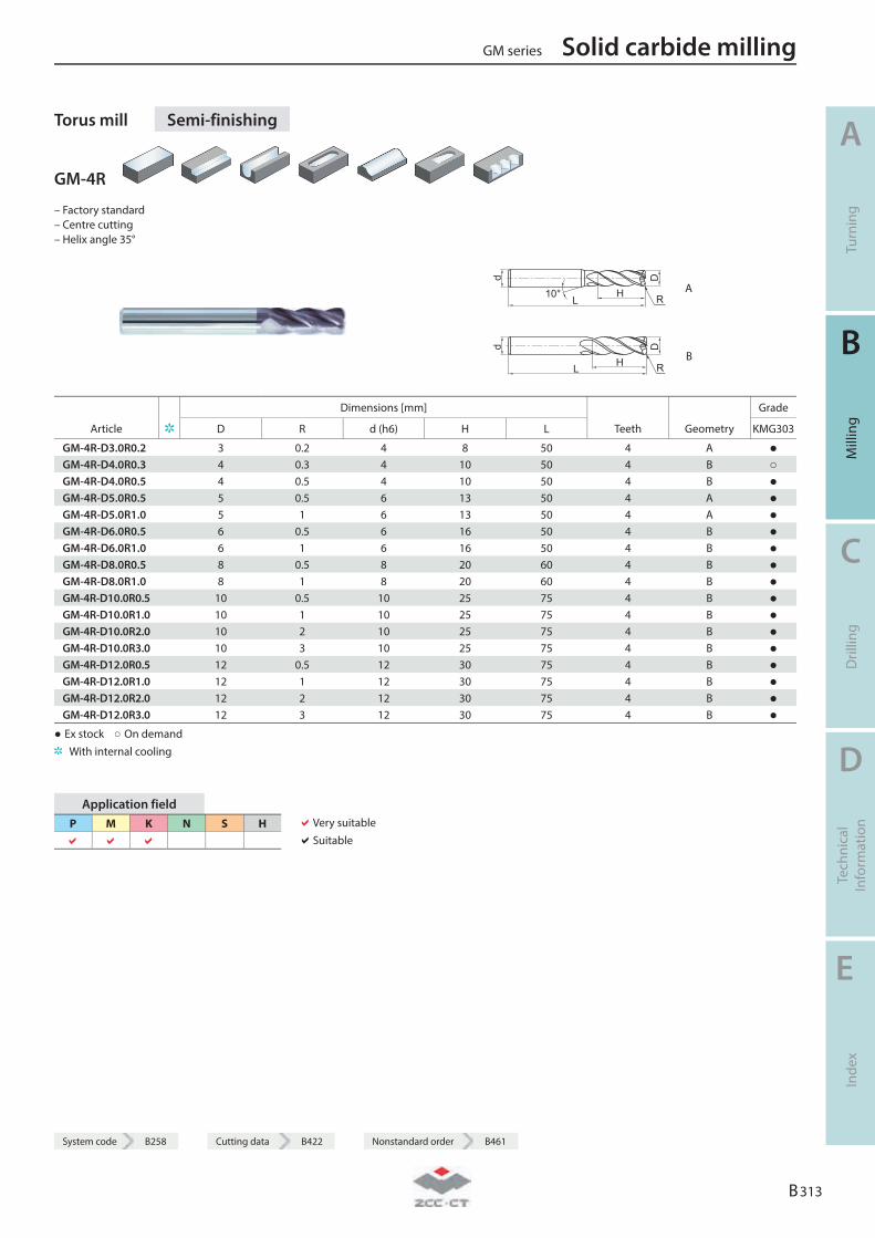
System code B258 Cutting data B422 Nonstandard order B461
Torus mill Semi-finishing
GM-4R
– Factory standard – Centre cutting – Helix angle 35°
R A
R B
Dimensions [mm] Grade
Article D R d (h6) H L Teeth Geometry KMG303
GM-4R-D3.0R0.2 3 0.2 4 8 50 4 A ● GM-4R-D4.0R0.3 4 0.3 4 10 50 4 B ○ GM-4R-D4.0R0.5 4 0.5 4 10 50 4 B ● GM-4R-D5.0R0.5 5 0.5 6 13 50 4 A ● GM-4R-D5.0R1.0 5 1 6 13 50 4 A ● GM-4R-D6.0R0.5 6 0.5 6 16 50 4 B ● GM-4R-D6.0R1.0 6 1 6 16 50 4 B ● GM-4R-D8.0R0.5 8 0.5 8 20 60 4 B ● GM-4R-D8.0R1.0 8 1 8 20 60 4 B ● GM-4R-D10.0R0.5 10 0.5 10 25 75 4 B ● GM-4R-D10.0R1.0 10 1 10 25 75 4 B ● GM-4R-D10.0R2.0 10 2 10 25 75 4 B ● GM-4R-D10.0R3.0 10 3 10 25 75 4 B ● GM-4R-D12.0R0.5 12 0.5 12 30 75 4 B ● GM-4R-D12.0R1.0 12 1 12 30 75 4 B ● GM-4R-D12.0R2.0 12 2 12 30 75 4 B ● GM-4R-D12.0R3.0 12 3 12 30 75 4 B ●
● Ex stock ○ On demand With internal cooling
Application field P M K N S H
Very suitable Suitable
GM series Solid carbide milling
A
Turn
ing
B
Mill
ing
C
Dril
ling
D
Tech
nica
l In
form
atio
n
E
Inde
x
B 313
System code B258 Cutting data B422 Nonstandard order B461
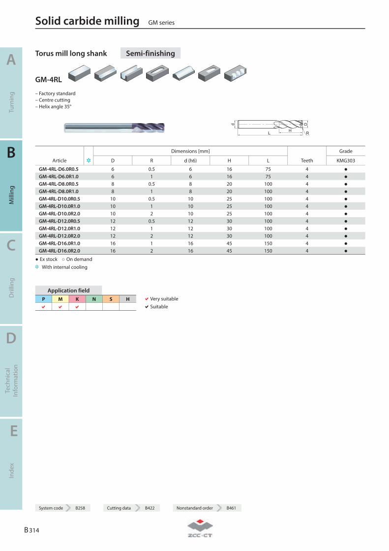
Torus mill long shank Semi-finishing
GM-4RL
– Factory standard – Centre cutting – Helix angle 35°
d
L H
D
R
Dimensions [mm] Grade
Article D R d (h6) H L Teeth KMG303
GM-4RL-D6.0R0.5 6 0.5 6 16 75 4 ● GM-4RL-D6.0R1.0 6 1 6 16 75 4 ● GM-4RL-D8.0R0.5 8 0.5 8 20 100 4 ● GM-4RL-D8.0R1.0 8 1 8 20 100 4 ● GM-4RL-D10.0R0.5 10 0.5 10 25 100 4 ● GM-4RL-D10.0R1.0 10 1 10 25 100 4 ● GM-4RL-D10.0R2.0 10 2 10 25 100 4 ● GM-4RL-D12.0R0.5 12 0.5 12 30 100 4 ● GM-4RL-D12.0R1.0 12 1 12 30 100 4 ● GM-4RL-D12.0R2.0 12 2 12 30 100 4 ● GM-4RL-D16.0R1.0 16 1 16 45 150 4 ● GM-4RL-D16.0R2.0 16 2 16 45 150 4 ●
● Ex stock ○ On demand With internal cooling
Application field P M K N S H
Very suitable Suitable
Solid carbide milling GM series
A
Turn
ing
B
Mill
ing
C
Dril
ling
D
Tech
nica
l In
form
atio
n
E
Inde
x
B 314
System code B258 Cutting data B422 Nonstandard order B461
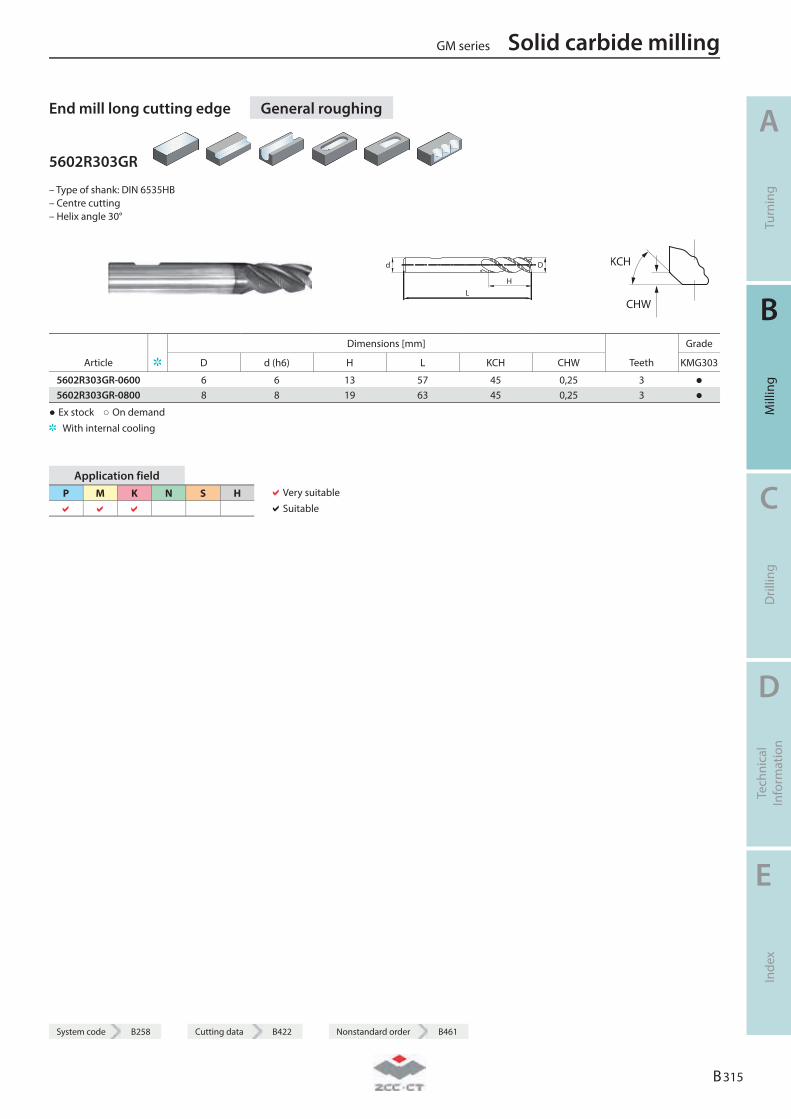
System code B258 Cutting data B422 Nonstandard order B461
End mill long cutting edge General roughing
5602R303GR
– Type of shank: DIN 6535HB – Centre cutting – Helix angle 30°
LH
Dd
KCH
CHW
Dimensions [mm] Grade
Article D d (h6) H L KCH CHW Teeth KMG303
5602R303GR-0600 6 6 13 57 45 0,25 3 ● 5602R303GR-0800 8 8 19 63 45 0,25 3 ●
● Ex stock ○ On demand With internal cooling
Application field P M K N S H
Very suitable Suitable
GM series Solid carbide milling
A
Turn
ing
B
Mill
ing
C
Dril
ling
D
Tech
nica
l In
form
atio
n
E
Inde
x
B 315
System code B258 Cutting data B422 Nonstandard order B461
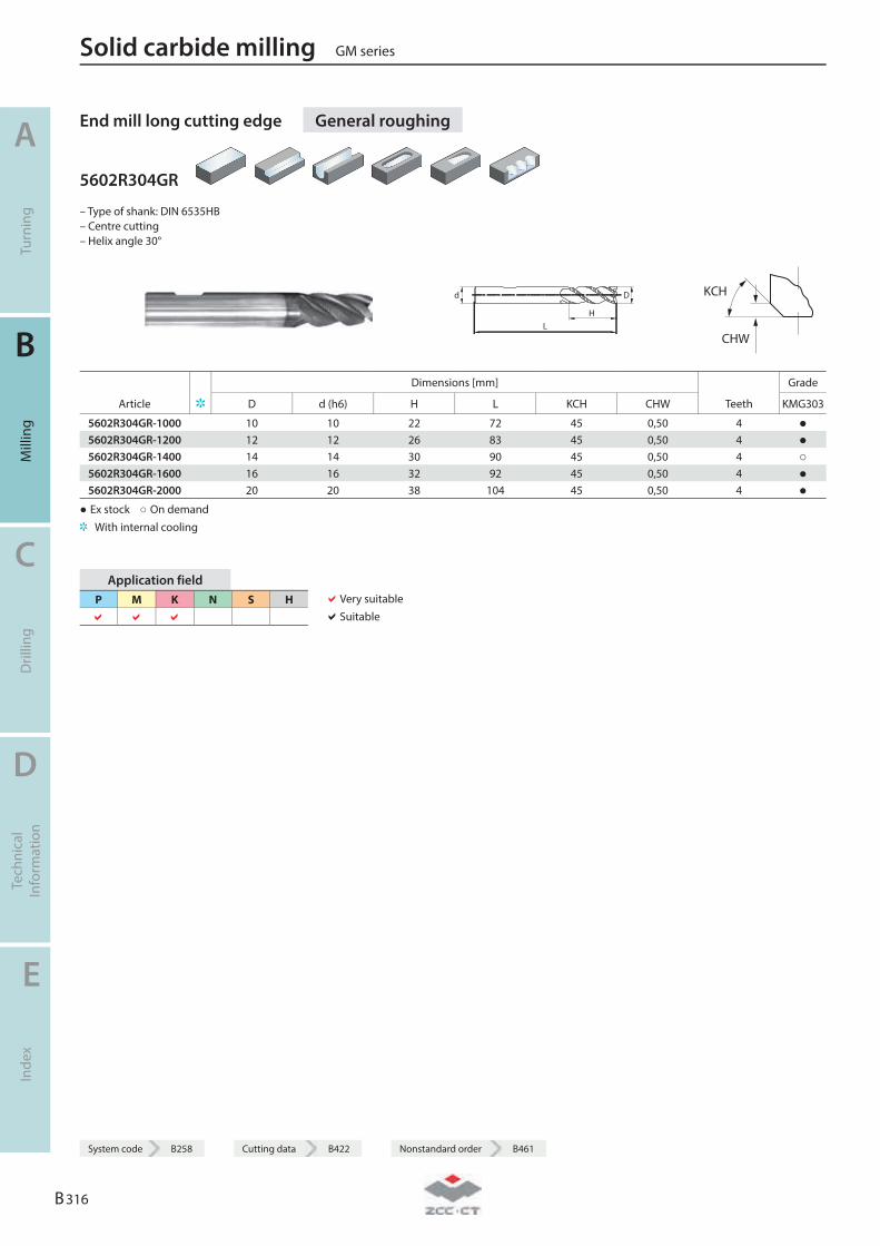
End mill long cutting edge General roughing
5602R304GR
– Type of shank: DIN 6535HB – Centre cutting – Helix angle 30°
LH
Dd
KCH
CHW
Dimensions [mm] Grade
Article D d (h6) H L KCH CHW Teeth KMG303
5602R304GR-1000 10 10 22 72 45 0,50 4 ● 5602R304GR-1200 12 12 26 83 45 0,50 4 ● 5602R304GR-1400 14 14 30 90 45 0,50 4 ○ 5602R304GR-1600 16 16 32 92 45 0,50 4 ● 5602R304GR-2000 20 20 38 104 45 0,50 4 ●
● Ex stock ○ On demand With internal cooling
Application field P M K N S H
Very suitable Suitable
Solid carbide milling GM series
A
Turn
ing
B
Mill
ing
C
Dril
ling
D
Tech
nica
l In
form
atio
n
E
Inde
x
B 316
System code B258 Cutting data B422 Nonstandard order B461
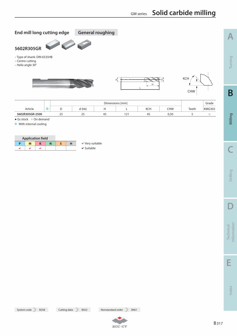
System code B258 Cutting data B422 Nonstandard order B461
End mill long cutting edge General roughing
5602R305GR
– Type of shank: DIN 6535HB – Centre cutting – Helix angle 30°
LH
Dd
KCH
CHW
Dimensions [mm] Grade
Article D d (h6) H L KCH CHW Teeth KMG303
5602R305GR-2500 25 25 45 121 45 0,50 5 ○ ● Ex stock ○ On demand With internal cooling
Application field P M K N S H
Very suitable Suitable
GM series Solid carbide milling
A
Turn
ing
B
Mill
ing
C
Dril
ling
D
Tech
nica
l In
form
atio
n
E
Inde
x
B 317
System code B258 Cutting data B422 Nonstandard order B461
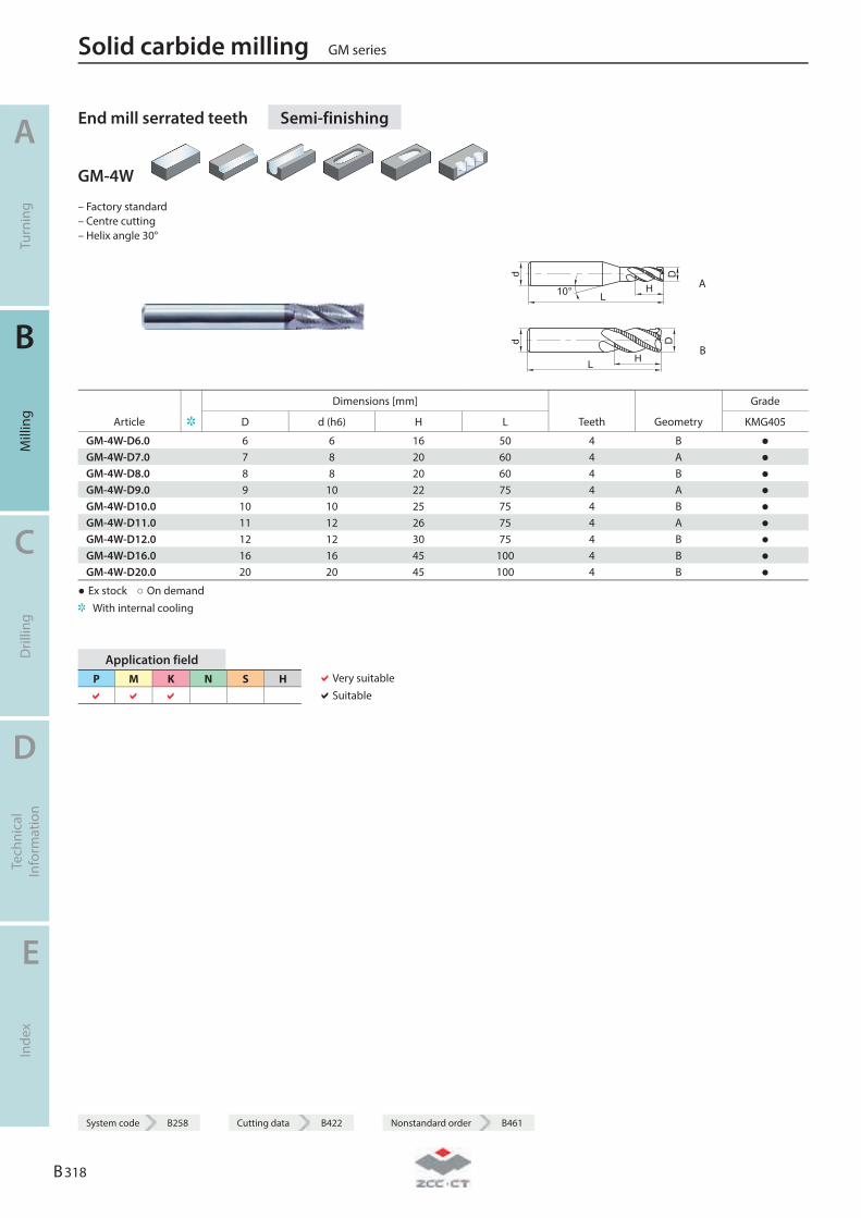
End mill serrated teeth Semi-finishing
GM-4W
– Factory standard – Centre cutting – Helix angle 30°
L
Dd
10° H A
d
L H
D
B
Dimensions [mm] Grade
Article D d (h6) H L Teeth Geometry KMG405
GM-4W-D6.0 6 6 16 50 4 B ● GM-4W-D7.0 7 8 20 60 4 A ● GM-4W-D8.0 8 8 20 60 4 B ● GM-4W-D9.0 9 10 22 75 4 A ● GM-4W-D10.0 10 10 25 75 4 B ● GM-4W-D11.0 11 12 26 75 4 A ● GM-4W-D12.0 12 12 30 75 4 B ● GM-4W-D16.0 16 16 45 100 4 B ● GM-4W-D20.0 20 20 45 100 4 B ●
● Ex stock ○ On demand With internal cooling
Application field P M K N S H
Very suitable Suitable
Solid carbide milling GM series
A
Turn
ing
B
Mill
ing
C
Dril
ling
D
Tech
nica
l In
form
atio
n
E
Inde
x
B 318
System code B258 Cutting data B422 Nonstandard order B461
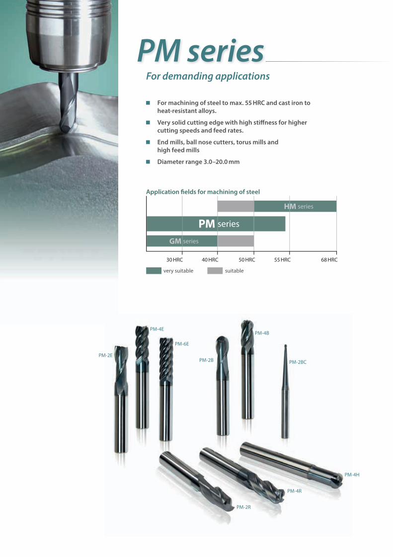
PM series
Application fi elds for machining of steel
30 HRC 40 HRC 50 HRC 55 HRC 68 HRC
very suitable suitable
HM series
PM series
GM series
For demanding applications
For machining of steel to max. 55 HRC and cast iron to heat-resistant alloys.
Very solid cutting edge with high stiff ness for higher cutting speeds and feed rates.
End mills, ball nose cutters, torus mills and high feed mills
Diameter range 3.0–20.0 mm
PM-4EPM-4B
PM-4H
PM-4R
PM-2R
PM-2BC
PM-6E
PM-2EPM-2B
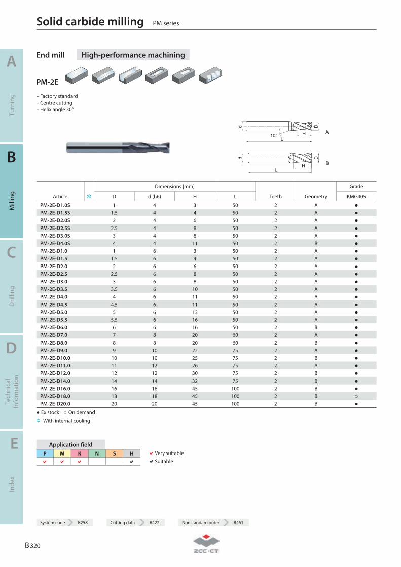
End mill High-performance machining
PM-2E
– Factory standard – Centre cutting – Helix angle 30°
L
d
H
D
10° A
L
D
H
d
B
Dimensions [mm] Grade
Article D d (h6) H L Teeth Geometry KMG405
PM-2E-D1.0S 1 4 3 50 2 A ● PM-2E-D1.5S 1.5 4 4 50 2 A ● PM-2E-D2.0S 2 4 6 50 2 A ● PM-2E-D2.5S 2.5 4 8 50 2 A ● PM-2E-D3.0S 3 4 8 50 2 A ● PM-2E-D4.0S 4 4 11 50 2 B ● PM-2E-D1.0 1 6 3 50 2 A ● PM-2E-D1.5 1.5 6 4 50 2 A ● PM-2E-D2.0 2 6 6 50 2 A ● PM-2E-D2.5 2.5 6 8 50 2 A ● PM-2E-D3.0 3 6 8 50 2 A ● PM-2E-D3.5 3.5 6 10 50 2 A ● PM-2E-D4.0 4 6 11 50 2 A ● PM-2E-D4.5 4.5 6 11 50 2 A ● PM-2E-D5.0 5 6 13 50 2 A ● PM-2E-D5.5 5.5 6 16 50 2 A ● PM-2E-D6.0 6 6 16 50 2 B ● PM-2E-D7.0 7 8 20 60 2 A ● PM-2E-D8.0 8 8 20 60 2 B ● PM-2E-D9.0 9 10 22 75 2 A ● PM-2E-D10.0 10 10 25 75 2 B ● PM-2E-D11.0 11 12 26 75 2 A ● PM-2E-D12.0 12 12 30 75 2 B ● PM-2E-D14.0 14 14 32 75 2 B ● PM-2E-D16.0 16 16 45 100 2 B ● PM-2E-D18.0 18 18 45 100 2 B ○ PM-2E-D20.0 20 20 45 100 2 B ●
● Ex stock ○ On demand With internal cooling
Application field P M K N S H
Very suitable Suitable
Solid carbide milling PM series
A
Turn
ing
B
Mill
ing
C
Dril
ling
D
Tech
nica
l In
form
atio
n
E
Inde
x
B 320
System code B258 Cutting data B422 Nonstandard order B461

System code B258 Cutting data B422 Nonstandard order B461
End mill long cutting edge High-performance machining
PM-2EL
– Factory standard – Centre cutting – Helix angle 30°
L
d
H
D
10° A
L
D
H
d
B
Dimensions [mm] Grade
Article D d (h6) H L Teeth Geometry KMG405
PM-2EL-D3.0 3 6 12 75 2 A ● PM-2EL-D4.0 4 6 15 75 2 A ● PM-2EL-D5.0 5 6 20 75 2 A ● PM-2EL-D6.0 6 6 20 75 2 B ● PM-2EL-D8.0 8 8 25 100 2 B ● PM-2EL-D10.0 10 10 30 100 2 B ● PM-2EL-D12.0 12 12 35 100 2 B ● PM-2EL-D14.0 14 14 40 100 2 B ● PM-2EL-D16.0 16 16 50 150 2 B ● PM-2EL-D20.0 20 20 55 150 2 B ●
● Ex stock ○ On demand With internal cooling
Application field P M K N S H
Very suitable Suitable
PM series Solid carbide milling
A
Turn
ing
B
Mill
ing
C
Dril
ling
D
Tech
nica
l In
form
atio
n
E
Inde
x
B 321
System code B258 Cutting data B422 Nonstandard order B461

End mill High-performance machining
PM-4E-G
– Factory standard – Centre cutting – Helix angle 30°
d
L10° H
D
A
d
L H
D
B
Dimensions [mm] Grade
Article D d (h6) H L Teeth Geometry KMG405
PM-4E-D1.0S-G 1 4 3 50 4 A ● PM-4E-D1.5S-G 1.5 4 4 50 4 A ● PM-4E-D2.0S-G 2 4 6 50 4 A ● PM-4E-D2.5S-G 2.5 4 8 50 4 A ● PM-4E-D3.0S-G 3 4 8 50 4 A ● PM-4E-D4.0S-G 4 4 11 50 4 B ● PM-4E-D1.0-G 1 6 3 50 4 A ● PM-4E-D1.5-G 1.5 6 4 50 4 A ● PM-4E-D2.0-G 2 6 6 50 4 A ● PM-4E-D2.5-G 2.5 6 8 50 4 A ● PM-4E-D3.0-G 3 6 8 50 4 A ● PM-4E-D3.5-G 3.5 6 10 50 4 A ● PM-4E-D4.0-G 4 6 11 50 4 A ● PM-4E-D4.5-G 4.5 6 11 50 4 A ● PM-4E-D5.0-G 5 6 13 50 4 A ● PM-4E-D5.5-G 5.5 6 16 50 4 A ● PM-4E-D6.0-G 6 6 16 50 4 B ● PM-4E-D7.0-G 7 8 20 60 4 A ● PM-4E-D8.0-G 8 8 20 60 4 B ● PM-4E-D9.0-G 9 10 22 75 4 A ● PM-4E-D10.0-G 10 10 25 75 4 B ● PM-4E-D11.0-G 11 12 26 75 4 A ● PM-4E-D12.0-G 12 12 30 75 4 B ● PM-4E-D14.0-G 14 14 32 75 4 B ● PM-4E-D16.0-G 16 16 45 100 4 B ● PM-4E-D18.0-G 18 18 45 100 4 B ● PM-4E-D20.0-G 20 20 45 100 4 B ●
● Ex stock ○ On demand With internal cooling
Application field P M K N S H
Very suitable Suitable
Solid carbide milling PM series
A
Turn
ing
B
Mill
ing
C
Dril
ling
D
Tech
nica
l In
form
atio
n
E
Inde
x
B 322
System code B258 Cutting data B422 Nonstandard order B461

System code B258 Cutting data B422 Nonstandard order B461
End mill long cutting edge High-performance machining
PM-4EL-G
– Factory standard – Centre cutting – Helix angle 30°
d
L10° H
D
A
d
L H
D
B
Dimensions [mm] Grade
Article D d (h6) H L Teeth Geometry KMG405
PM-4EL-D3.0-G 3 6 12 75 4 A ● PM-4EL-D4.0-G 4 6 15 75 4 A ● PM-4EL-D5.0-G 5 6 20 75 4 A ● PM-4EL-D6.0-G 6 6 20 75 4 B ● PM-4EL-D8.0-G 8 8 25 100 4 B ● PM-4EL-D10.0-G 10 10 30 100 4 B ● PM-4EL-D12.0-G 12 12 35 100 4 B ● PM-4EL-D14.0-G 14 14 40 100 4 B ● PM-4EL-D16.0-G 16 16 50 150 4 B ● PM-4EL-D20.0-G 20 20 55 150 4 B ●
● Ex stock ○ On demand With internal cooling
Application field P M K N S H
Very suitable Suitable
PM series Solid carbide milling
A
Turn
ing
B
Mill
ing
C
Dril
ling
D
Tech
nica
l In
form
atio
n
E
Inde
x
B 323
System code B258 Cutting data B422 Nonstandard order B461
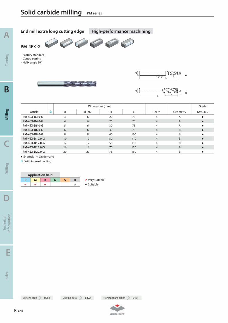
End mill extra long cutting edge High-performance machining
PM-4EX-G
– Factory standard – Centre cutting – Helix angle 30°
d
L10° H
D
A
d
L H
D
B
Dimensions [mm] Grade
Article D d (h6) H L Teeth Geometry KMG405
PM-4EX-D3.0-G 3 6 20 75 4 A ● PM-4EX-D4.0-G 4 6 25 75 4 A ● PM-4EX-D5.0-G 5 6 30 75 4 A ● PM-4EX-D6.0-G 6 6 30 75 4 B ● PM-4EX-D8.0-G 8 8 40 100 4 B ● PM-4EX-D10.0-G 10 10 50 110 4 B ● PM-4EX-D12.0-G 12 12 50 110 4 B ● PM-4EX-D16.0-G 16 16 70 150 4 B ● PM-4EX-D20.0-G 20 20 75 150 4 B ●
● Ex stock ○ On demand With internal cooling
Application field P M K N S H
Very suitable Suitable
Solid carbide milling PM series
A
Turn
ing
B
Mill
ing
C
Dril
ling
D
Tech
nica
l In
form
atio
n
E
Inde
x
B 324
System code B258 Cutting data B422 Nonstandard order B461
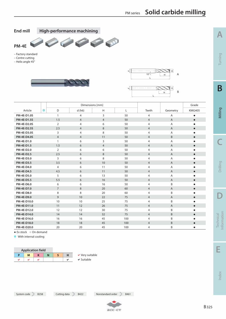
System code B258 Cutting data B422 Nonstandard order B461
End mill High-performance machining
PM-4E
– Factory standard – Centre cutting – Helix angle 45°
L
D
H10°
d
A
LH
Dd
B
Dimensions [mm] Grade
Article D d (h6) H L Teeth Geometry KMG405
PM-4E-D1.0S 1 4 3 50 4 A ● PM-4E-D1.5S 1.5 4 4 50 4 A ● PM-4E-D2.0S 2 4 6 50 4 A ● PM-4E-D2.5S 2.5 4 8 50 4 A ● PM-4E-D3.0S 3 4 8 50 4 A ● PM-4E-D4.0S 4 4 11 50 4 B ● PM-4E-D1.0 1 6 3 50 4 A ● PM-4E-D1.5 1.5 6 4 50 4 A ● PM-4E-D2.0 2 6 6 50 4 A ● PM-4E-D2.5 2.5 6 8 50 4 A ● PM-4E-D3.0 3 6 8 50 4 A ● PM-4E-D3.5 3.5 6 10 50 4 A ● PM-4E-D4.0 4 6 11 50 4 A ● PM-4E-D4.5 4.5 6 11 50 4 A ● PM-4E-D5.0 5 6 13 50 4 A ● PM-4E-D5.5 5.5 6 16 50 4 A ● PM-4E-D6.0 6 6 16 50 4 B ● PM-4E-D7.0 7 8 20 60 4 A ● PM-4E-D8.0 8 8 20 60 4 B ● PM-4E-D9.0 9 10 22 75 4 A ● PM-4E-D10.0 10 10 25 75 4 B ● PM-4E-D11.0 11 12 26 75 4 A ● PM-4E-D12.0 12 12 30 75 4 B ● PM-4E-D14.0 14 14 32 75 4 B ● PM-4E-D16.0 16 16 45 100 4 B ● PM-4E-D18.0 18 18 45 100 4 B ● PM-4E-D20.0 20 20 45 100 4 B ●
● Ex stock ○ On demand With internal cooling
Application field P M K N S H
Very suitable Suitable
PM series Solid carbide milling
A
Turn
ing
B
Mill
ing
C
Dril
ling
D
Tech
nica
l In
form
atio
n
E
Inde
x
B 325
System code B258 Cutting data B422 Nonstandard order B461
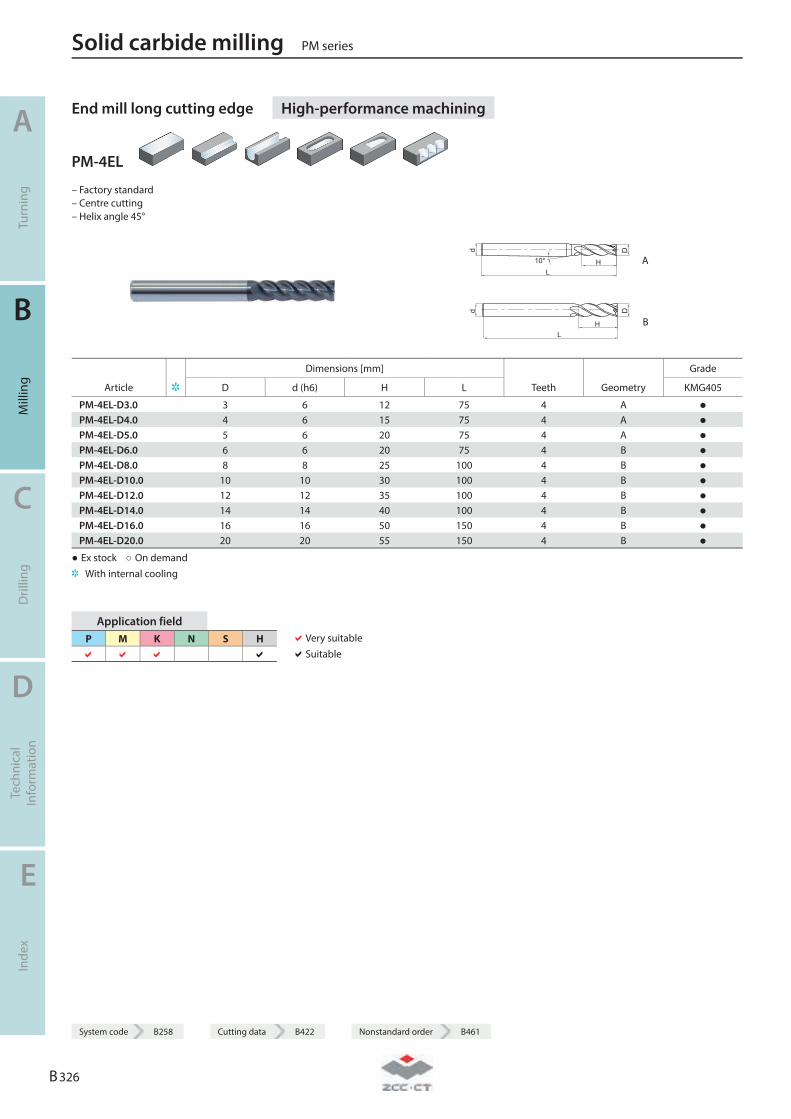
End mill long cutting edge High-performance machining
PM-4EL
– Factory standard – Centre cutting – Helix angle 45°
L
D
H10°
d
A
LH
Dd
B
Dimensions [mm] Grade
Article D d (h6) H L Teeth Geometry KMG405
PM-4EL-D3.0 3 6 12 75 4 A ● PM-4EL-D4.0 4 6 15 75 4 A ● PM-4EL-D5.0 5 6 20 75 4 A ● PM-4EL-D6.0 6 6 20 75 4 B ● PM-4EL-D8.0 8 8 25 100 4 B ● PM-4EL-D10.0 10 10 30 100 4 B ● PM-4EL-D12.0 12 12 35 100 4 B ● PM-4EL-D14.0 14 14 40 100 4 B ● PM-4EL-D16.0 16 16 50 150 4 B ● PM-4EL-D20.0 20 20 55 150 4 B ●
● Ex stock ○ On demand With internal cooling
Application field P M K N S H
Very suitable Suitable
Solid carbide milling PM series
A
Turn
ing
B
Mill
ing
C
Dril
ling
D
Tech
nica
l In
form
atio
n
E
Inde
x
B 326
System code B258 Cutting data B422 Nonstandard order B461
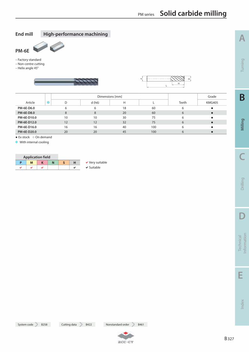
System code B258 Cutting data B422 Nonstandard order B461
End mill High-performance machining
PM-6E
– Factory standard – Non-centre cutting – Helix angle 45°
L
D
H
d
Dimensions [mm] Grade
Article D d (h6) H L Teeth KMG405
PM-6E-D6.0 6 6 18 60 6 ● PM-6E-D8.0 8 8 20 60 6 ● PM-6E-D10.0 10 10 30 75 6 ● PM-6E-D12.0 12 12 32 75 6 ● PM-6E-D16.0 16 16 40 100 6 ● PM-6E-D20.0 20 20 45 100 6 ●
● Ex stock ○ On demand With internal cooling
Application field P M K N S H
Very suitable Suitable
PM series Solid carbide milling
A
Turn
ing
B
Mill
ing
C
Dril
ling
D
Tech
nica
l In
form
atio
n
E
Inde
x
B 327
System code B258 Cutting data B422 Nonstandard order B461
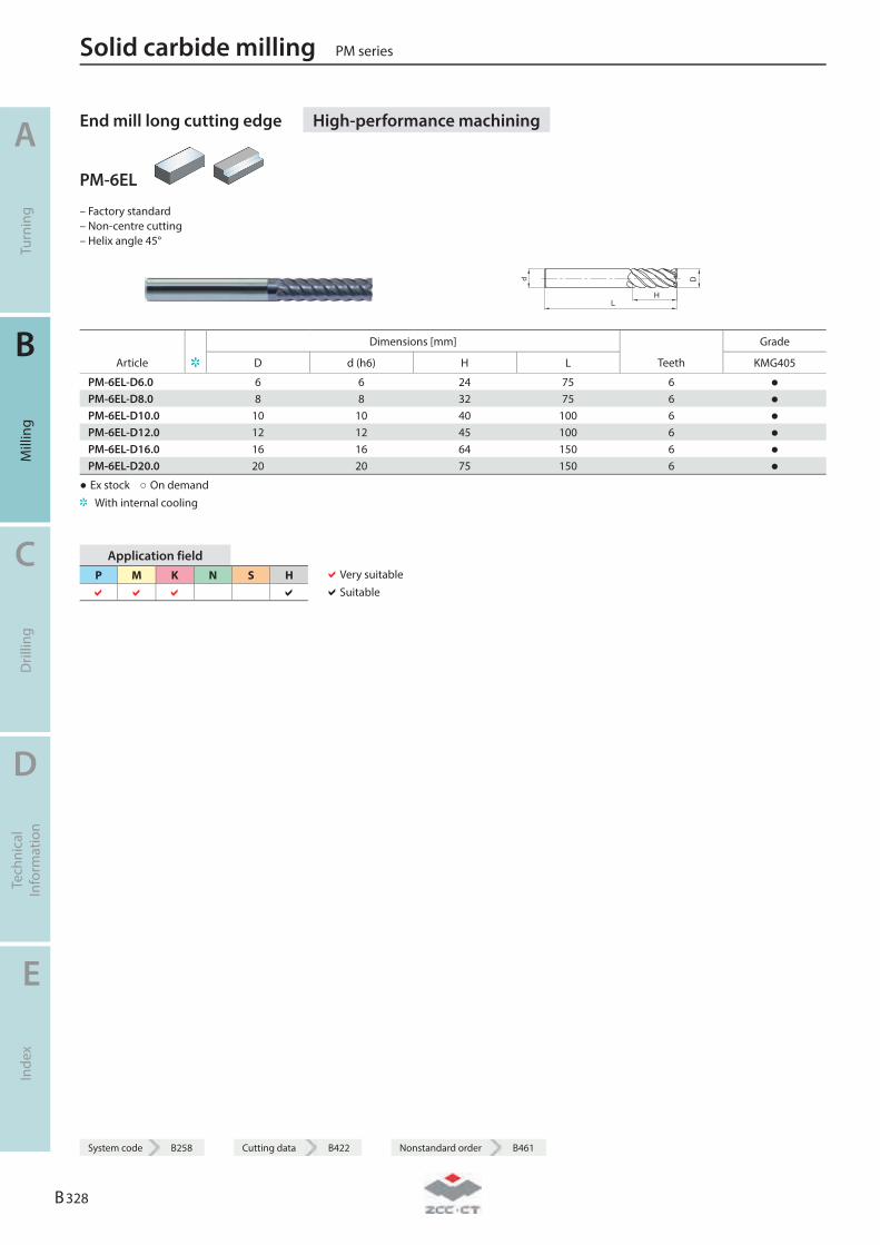
End mill long cutting edge High-performance machining
PM-6EL
– Factory standard – Non-centre cutting – Helix angle 45°
L
D
H
d
Dimensions [mm] Grade
Article D d (h6) H L Teeth KMG405
PM-6EL-D6.0 6 6 24 75 6 ● PM-6EL-D8.0 8 8 32 75 6 ● PM-6EL-D10.0 10 10 40 100 6 ● PM-6EL-D12.0 12 12 45 100 6 ● PM-6EL-D16.0 16 16 64 150 6 ● PM-6EL-D20.0 20 20 75 150 6 ●
● Ex stock ○ On demand With internal cooling
Application field P M K N S H
Very suitable Suitable
Solid carbide milling PM series
A
Turn
ing
B
Mill
ing
C
Dril
ling
D
Tech
nica
l In
form
atio
n
E
Inde
x
B 328
System code B258 Cutting data B422 Nonstandard order B461
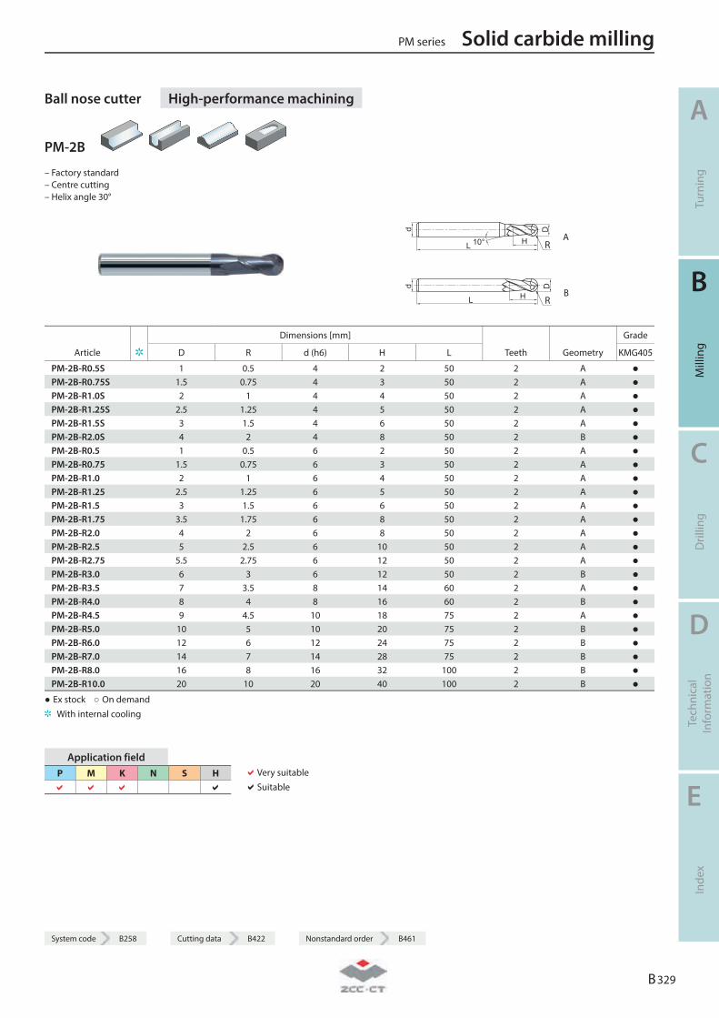
System code B258 Cutting data B422 Nonstandard order B461
Ball nose cutter High-performance machining
PM-2B
– Factory standard – Centre cutting – Helix angle 30°
R A
R B
Dimensions [mm] Grade
Article D R d (h6) H L Teeth Geometry KMG405
PM-2B-R0.5S 1 0.5 4 2 50 2 A ● PM-2B-R0.75S 1.5 0.75 4 3 50 2 A ● PM-2B-R1.0S 2 1 4 4 50 2 A ● PM-2B-R1.25S 2.5 1.25 4 5 50 2 A ● PM-2B-R1.5S 3 1.5 4 6 50 2 A ● PM-2B-R2.0S 4 2 4 8 50 2 B ● PM-2B-R0.5 1 0.5 6 2 50 2 A ● PM-2B-R0.75 1.5 0.75 6 3 50 2 A ● PM-2B-R1.0 2 1 6 4 50 2 A ● PM-2B-R1.25 2.5 1.25 6 5 50 2 A ● PM-2B-R1.5 3 1.5 6 6 50 2 A ● PM-2B-R1.75 3.5 1.75 6 8 50 2 A ● PM-2B-R2.0 4 2 6 8 50 2 A ● PM-2B-R2.5 5 2.5 6 10 50 2 A ● PM-2B-R2.75 5.5 2.75 6 12 50 2 A ● PM-2B-R3.0 6 3 6 12 50 2 B ● PM-2B-R3.5 7 3.5 8 14 60 2 A ● PM-2B-R4.0 8 4 8 16 60 2 B ● PM-2B-R4.5 9 4.5 10 18 75 2 A ● PM-2B-R5.0 10 5 10 20 75 2 B ● PM-2B-R6.0 12 6 12 24 75 2 B ● PM-2B-R7.0 14 7 14 28 75 2 B ● PM-2B-R8.0 16 8 16 32 100 2 B ● PM-2B-R10.0 20 10 20 40 100 2 B ●
● Ex stock ○ On demand With internal cooling
Application field P M K N S H
Very suitable Suitable
PM series Solid carbide milling
A
Turn
ing
B
Mill
ing
C
Dril
ling
D
Tech
nica
l In
form
atio
n
E
Inde
x
B 329
System code B258 Cutting data B422 Nonstandard order B461

Ball nose cutter long shank High-performance machining
PM-2BL
– Factory standard – Centre cutting – Helix angle 30°
A
B
Dimensions [mm] Grade
Article D R d (h6) H L Teeth Geometry KMG405
PM-2BL-R1.0 2 1 6 4 75 2 A ● PM-2BL-R1.25 2.5 1.25 6 5 75 2 A ● PM-2BL-R1.5 3 1.5 6 6 75 2 A ● PM-2BL-R1.75 3.5 1.75 6 8 75 2 A ● PM-2BL-R2.0 4 2 6 8 75 2 A ● PM-2BL-R2.5 5 2.5 6 10 75 2 A ● PM-2BL-R2.75 5.5 2.75 6 12 75 2 A ● PM-2BL-R3.0 6 3 6 12 75 2 B ● PM-2BL-R3.5 7 3.5 8 14 75 2 A ● PM-2BL-R4.0 8 4 8 16 100 2 B ● PM-2BL-R4.5 9 4.5 10 18 100 2 A ● PM-2BL-R5.0 10 5 10 20 100 2 B ● PM-2BL-R6.0 12 6 12 24 100 2 B ● PM-2BL-R7.0 14 7 14 28 100 2 B ● PM-2BL-R8.0 16 8 16 32 150 2 B ● PM-2BL-R10.0 20 10 20 40 150 2 B ●
● Ex stock ○ On demand With internal cooling
Application field P M K N S H
Very suitable Suitable
Solid carbide milling PM series
A
Turn
ing
B
Mill
ing
C
Dril
ling
D
Tech
nica
l In
form
atio
n
E
Inde
x
B 330
System code B258 Cutting data B422 Nonstandard order B461
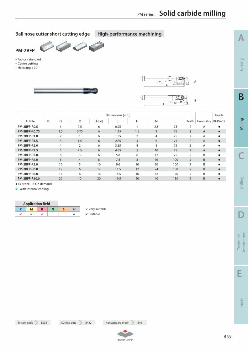
System code B258 Cutting data B422 Nonstandard order B461
Ball nose cutter short cutting edge High-performance machining
PM-2BFP
– Factory standard – Centre cutting – Helix angle 30°
d
L10° HMd1
D
R A
d
LHMd1
D
R B
Dimensions [mm] Grade
Article D R d (h6) d1 H M L Teeth Geometry KMG405
PM-2BFP-R0.5 1 0.5 6 0.95 1 2.5 75 2 A ● PM-2BFP-R0.75 1.5 0.75 6 1.45 1.5 3 75 2 A ● PM-2BFP-R1.0 2 1 6 1.95 2 4 75 2 A ● PM-2BFP-R1.5 3 1.5 6 2.85 3 6 75 2 A ● PM-2BFP-R2.0 4 2 6 3.85 4 8 75 2 A ● PM-2BFP-R2.5 5 2.5 6 4.85 5 10 75 2 A ● PM-2BFP-R3.0 6 3 6 5.8 6 12 75 2 B ● PM-2BFP-R4.0 8 4 8 7.8 8 16 100 2 B ● PM-2BFP-R5.0 10 5 10 9.6 10 20 100 2 B ● PM-2BFP-R6.0 12 6 12 11.5 12 24 100 2 B ● PM-2BFP-R8.0 16 8 16 15.5 16 32 150 2 B ● PM-2BFP-R10.0 20 10 20 19.5 20 40 150 2 B ●
● Ex stock ○ On demand With internal cooling
Application field P M K N S H
Very suitable Suitable
PM series Solid carbide milling
A
Turn
ing
B
Mill
ing
C
Dril
ling
D
Tech
nica
l In
form
atio
n
E
Inde
x
B 331
System code B258 Cutting data B422 Nonstandard order B461
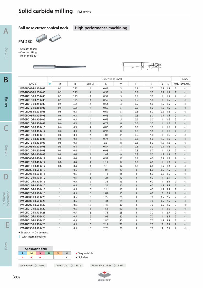
Ball nose cutter conical neck High-performance machining
PM-2BC
– Straight shank – Centre cutting – Helix angle 30°
d
L
d1
Mα l110° H
D
R
Dimensions [mm] Grade
Article D R d (h6) d1 M H L α l1 Teeth KMG405
PM-2BC05-R0.25-M03 0.5 0.25 4 0.49 3 0.5 50 0.5 1.5 2 ○ PM-2BC05-R0.25-M05 0.5 0.25 4 0.53 5 0.5 50 0.5 1.5 2 ○ PM-2BC10-R0.25-M03 0.5 0.25 4 0.52 3 0.5 50 1 1.5 2 ○ PM-2BC10-R0.25-M05 0.5 0.25 4 0.59 5 0.5 50 1 1.5 2 ○ PM-2BC15-R0.25-M03 0.5 0.25 4 0.54 3 0.5 50 1.5 1.5 2 ○ PM-2BC15-R0.25-M05 0.5 0.25 4 0.65 5 0.5 50 1.5 1.5 2 ○ PM-2BC05-R0.30-M05 0.6 0.3 4 0.62 5 0.6 50 0.5 1.6 2 ○ PM-2BC05-R0.30-M08 0.6 0.3 4 0.68 8 0.6 50 0.5 1.6 2 ○ PM-2BC10-R0.30-M05 0.6 0.3 4 0.68 5 0.6 50 1 1.6 2 ○ PM-2BC10-R0.30-M08 0.6 0.3 4 0.79 8 0.6 50 1 1.6 2 ○ PM-2BC10-R0.30-M10 0.6 0.3 4 0.86 10 0.6 50 1 1.6 2 ○ PM-2BC10-R0.30-M12 0.6 0.3 4 0.93 12 0.6 50 1 1.6 2 ○ PM-2BC10-R0.30-M15 0.6 0.3 4 1.03 15 0.6 50 1 1.6 2 ○ PM-2BC15-R0.30-M05 0.6 0.3 4 0.74 5 0.6 50 1.5 1.6 2 ○ PM-2BC15-R0.30-M08 0.6 0.3 4 0.9 8 0.6 50 1.5 1.6 2 ○ PM-2BC05-R0.40-M08 0.8 0.4 4 0.87 8 0.8 50 0.5 1.8 2 ○ PM-2BC10-R0.40-M08 0.8 0.4 4 0.98 8 0.8 50 1 1.8 2 ○ PM-2BC15-R0.40-M08 0.8 0.4 4 1.09 8 0.8 50 1.5 1.8 2 ○ PM-2BC05-R0.40-M12 0.8 0.4 4 0.94 12 0.8 60 0.5 1.8 2 ○ PM-2BC10-R0.40-M12 0.8 0.4 4 1.12 12 0.8 60 1 1.8 2 ○ PM-2BC15-R0.40-M12 0.8 0.4 4 1.3 12 0.8 60 1.5 1.8 2 ○ PM-2BC05-R0.50-M10 1 0.5 6 1.08 10 1 60 0.5 2.5 2 ○ PM-2BC05-R0.50-M15 1 0.5 6 1.16 15 1 60 0.5 2.5 2 ○ PM-2BC10-R0.50-M10 1 0.5 6 1.21 10 1 60 1 2.5 2 ○ PM-2BC10-R0.50-M15 1 0.5 6 1.38 15 1 60 1 2.5 2 ○ PM-2BC15-R0.50-M10 1 0.5 6 1.34 10 1 60 1.5 2.5 2 ○ PM-2BC15-R0.50-M15 1 0.5 6 1.6 15 1 60 1.5 2.5 2 ○ PM-2BC20-R0.50-M15 1 0.5 6 1.82 15 1 60 2 2.5 2 ○ PM-2BC05-R0.50-M20 1 0.5 6 1.25 20 1 70 0.5 2.5 2 ○ PM-2BC05-R0.50-M25 1 0.5 6 1.34 25 1 70 0.5 2.5 2 ○ PM-2BC05-R0.50-M30 1 0.5 6 1.42 30 1 70 0.5 2.5 2 ○ PM-2BC10-R0.50-M20 1 0.5 6 1.56 20 1 70 1 2.5 2 ○ PM-2BC10-R0.50-M25 1 0.5 6 1.73 25 1 70 1 2.5 2 ○ PM-2BC10-R0.50-M30 1 0.5 6 1.91 30 1 70 1 2.5 2 ○ PM-2BC15-R0.50-M20 1 0.5 6 1.86 20 1 70 1.5 2.5 2 ○ PM-2BC20-R0.50-M20 1 0.5 6 2.17 20 1 70 2 2.5 2 ○ PM-2BC30-R0.50-M20 1 0.5 6 2.78 20 1 70 3 2.5 2 ○
● Ex stock ○ On demand With internal cooling
Application field P M K N S H
Very suitable Suitable
Solid carbide milling PM series
A
Turn
ing
B
Mill
ing
C
Dril
ling
D
Tech
nica
l In
form
atio
n
E
Inde
x
B 332
System code B258 Cutting data B422 Nonstandard order B461
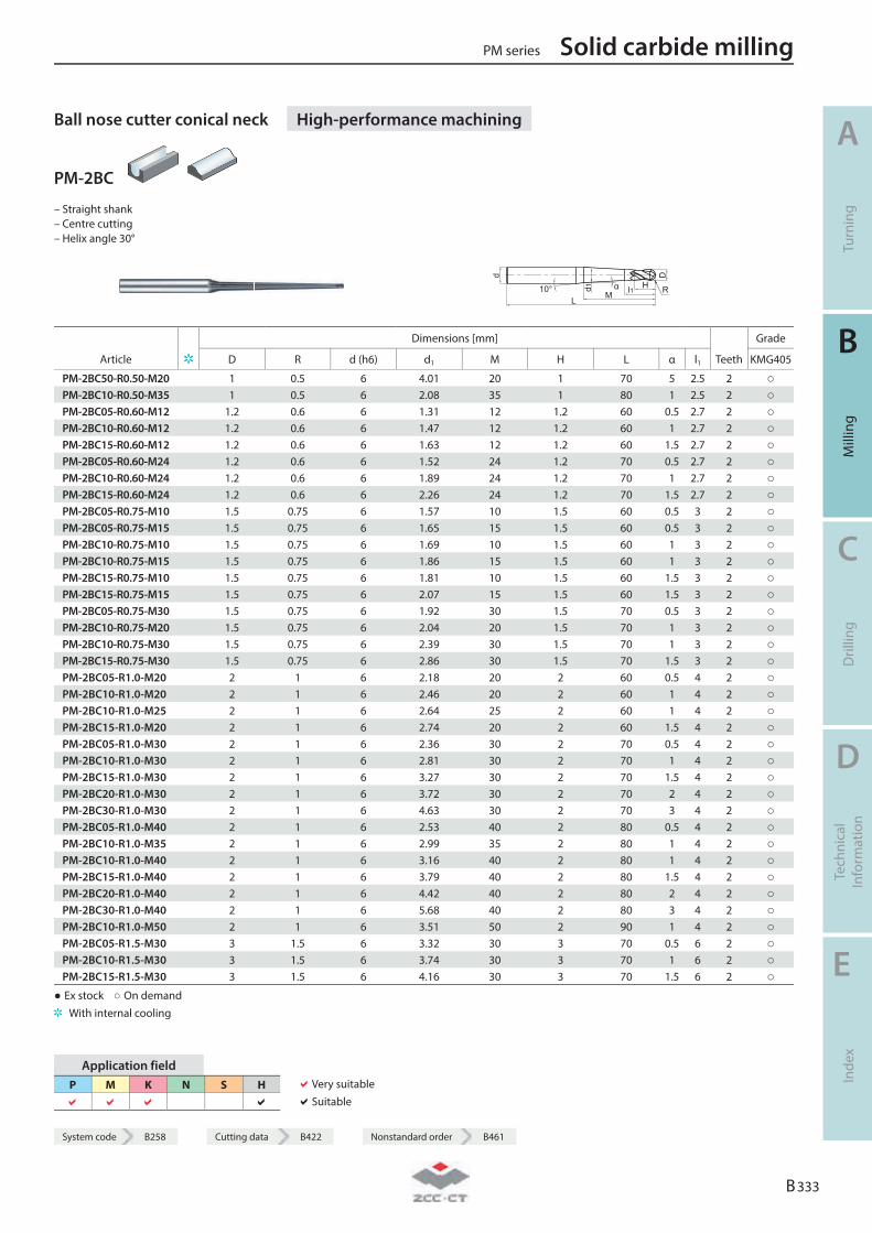
System code B258 Cutting data B422 Nonstandard order B461
Ball nose cutter conical neck High-performance machining
PM-2BC
– Straight shank – Centre cutting – Helix angle 30°
d
L
d1
Mα l110° H
D
R
Dimensions [mm] Grade
Article D R d (h6) d1 M H L α l1 Teeth KMG405
PM-2BC50-R0.50-M20 1 0.5 6 4.01 20 1 70 5 2.5 2 ○ PM-2BC10-R0.50-M35 1 0.5 6 2.08 35 1 80 1 2.5 2 ○ PM-2BC05-R0.60-M12 1.2 0.6 6 1.31 12 1.2 60 0.5 2.7 2 ○ PM-2BC10-R0.60-M12 1.2 0.6 6 1.47 12 1.2 60 1 2.7 2 ○ PM-2BC15-R0.60-M12 1.2 0.6 6 1.63 12 1.2 60 1.5 2.7 2 ○ PM-2BC05-R0.60-M24 1.2 0.6 6 1.52 24 1.2 70 0.5 2.7 2 ○ PM-2BC10-R0.60-M24 1.2 0.6 6 1.89 24 1.2 70 1 2.7 2 ○ PM-2BC15-R0.60-M24 1.2 0.6 6 2.26 24 1.2 70 1.5 2.7 2 ○ PM-2BC05-R0.75-M10 1.5 0.75 6 1.57 10 1.5 60 0.5 3 2 ○ PM-2BC05-R0.75-M15 1.5 0.75 6 1.65 15 1.5 60 0.5 3 2 ○ PM-2BC10-R0.75-M10 1.5 0.75 6 1.69 10 1.5 60 1 3 2 ○ PM-2BC10-R0.75-M15 1.5 0.75 6 1.86 15 1.5 60 1 3 2 ○ PM-2BC15-R0.75-M10 1.5 0.75 6 1.81 10 1.5 60 1.5 3 2 ○ PM-2BC15-R0.75-M15 1.5 0.75 6 2.07 15 1.5 60 1.5 3 2 ○ PM-2BC05-R0.75-M30 1.5 0.75 6 1.92 30 1.5 70 0.5 3 2 ○ PM-2BC10-R0.75-M20 1.5 0.75 6 2.04 20 1.5 70 1 3 2 ○ PM-2BC10-R0.75-M30 1.5 0.75 6 2.39 30 1.5 70 1 3 2 ○ PM-2BC15-R0.75-M30 1.5 0.75 6 2.86 30 1.5 70 1.5 3 2 ○ PM-2BC05-R1.0-M20 2 1 6 2.18 20 2 60 0.5 4 2 ○ PM-2BC10-R1.0-M20 2 1 6 2.46 20 2 60 1 4 2 ○ PM-2BC10-R1.0-M25 2 1 6 2.64 25 2 60 1 4 2 ○ PM-2BC15-R1.0-M20 2 1 6 2.74 20 2 60 1.5 4 2 ○ PM-2BC05-R1.0-M30 2 1 6 2.36 30 2 70 0.5 4 2 ○ PM-2BC10-R1.0-M30 2 1 6 2.81 30 2 70 1 4 2 ○ PM-2BC15-R1.0-M30 2 1 6 3.27 30 2 70 1.5 4 2 ○ PM-2BC20-R1.0-M30 2 1 6 3.72 30 2 70 2 4 2 ○ PM-2BC30-R1.0-M30 2 1 6 4.63 30 2 70 3 4 2 ○ PM-2BC05-R1.0-M40 2 1 6 2.53 40 2 80 0.5 4 2 ○ PM-2BC10-R1.0-M35 2 1 6 2.99 35 2 80 1 4 2 ○ PM-2BC10-R1.0-M40 2 1 6 3.16 40 2 80 1 4 2 ○ PM-2BC15-R1.0-M40 2 1 6 3.79 40 2 80 1.5 4 2 ○ PM-2BC20-R1.0-M40 2 1 6 4.42 40 2 80 2 4 2 ○ PM-2BC30-R1.0-M40 2 1 6 5.68 40 2 80 3 4 2 ○ PM-2BC10-R1.0-M50 2 1 6 3.51 50 2 90 1 4 2 ○ PM-2BC05-R1.5-M30 3 1.5 6 3.32 30 3 70 0.5 6 2 ○ PM-2BC10-R1.5-M30 3 1.5 6 3.74 30 3 70 1 6 2 ○ PM-2BC15-R1.5-M30 3 1.5 6 4.16 30 3 70 1.5 6 2 ○
● Ex stock ○ On demand With internal cooling
Application field P M K N S H
Very suitable Suitable
PM series Solid carbide milling
A
Turn
ing
B
Mill
ing
C
Dril
ling
D
Tech
nica
l In
form
atio
n
E
Inde
x
B 333
System code B258 Cutting data B422 Nonstandard order B461
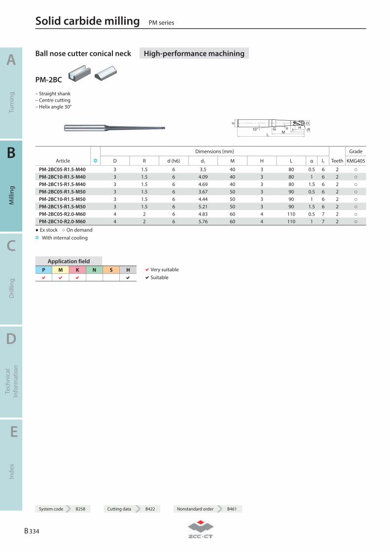
Ball nose cutter conical neck High-performance machining
PM-2BC
– Straight shank – Centre cutting – Helix angle 30°
d
L
d1
Mα l110° H
D
R
Dimensions [mm] Grade
Article D R d (h6) d1 M H L α l1 Teeth KMG405
PM-2BC05-R1.5-M40 3 1.5 6 3.5 40 3 80 0.5 6 2 ○ PM-2BC10-R1.5-M40 3 1.5 6 4.09 40 3 80 1 6 2 ○ PM-2BC15-R1.5-M40 3 1.5 6 4.69 40 3 80 1.5 6 2 ○ PM-2BC05-R1.5-M50 3 1.5 6 3.67 50 3 90 0.5 6 2 ○ PM-2BC10-R1.5-M50 3 1.5 6 4.44 50 3 90 1 6 2 ○ PM-2BC15-R1.5-M50 3 1.5 6 5.21 50 3 90 1.5 6 2 ○ PM-2BC05-R2.0-M60 4 2 6 4.83 60 4 110 0.5 7 2 ○ PM-2BC10-R2.0-M60 4 2 6 5.76 60 4 110 1 7 2 ○
● Ex stock ○ On demand With internal cooling
Application field P M K N S H
Very suitable Suitable
Solid carbide milling PM series
A
Turn
ing
B
Mill
ing
C
Dril
ling
D
Tech
nica
l In
form
atio
n
E
Inde
x
B 334
System code B258 Cutting data B422 Nonstandard order B461
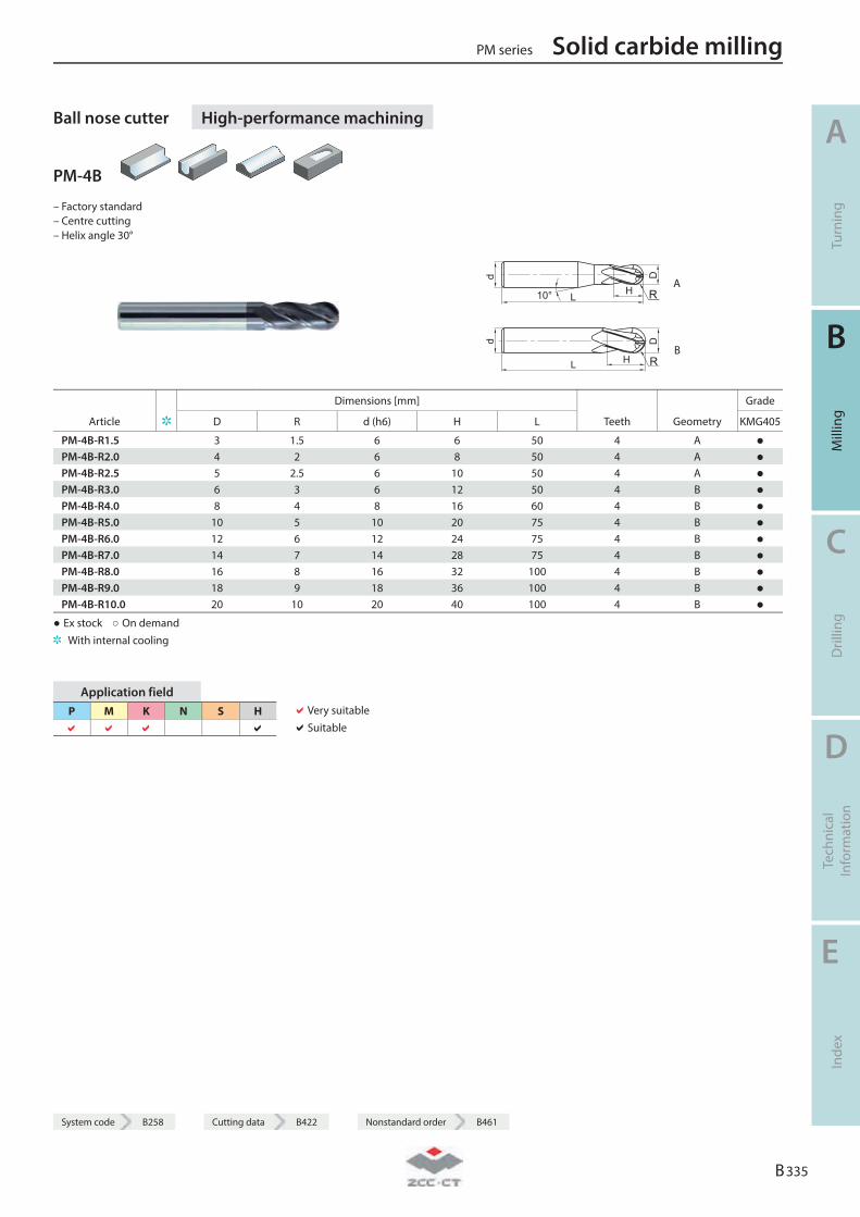
System code B258 Cutting data B422 Nonstandard order B461
Ball nose cutter High-performance machining
PM-4B
– Factory standard – Centre cutting – Helix angle 30°
d
L H
D
10° R A
d
L H
D
R B
Dimensions [mm] Grade
Article D R d (h6) H L Teeth Geometry KMG405
PM-4B-R1.5 3 1.5 6 6 50 4 A ● PM-4B-R2.0 4 2 6 8 50 4 A ● PM-4B-R2.5 5 2.5 6 10 50 4 A ● PM-4B-R3.0 6 3 6 12 50 4 B ● PM-4B-R4.0 8 4 8 16 60 4 B ● PM-4B-R5.0 10 5 10 20 75 4 B ● PM-4B-R6.0 12 6 12 24 75 4 B ● PM-4B-R7.0 14 7 14 28 75 4 B ● PM-4B-R8.0 16 8 16 32 100 4 B ● PM-4B-R9.0 18 9 18 36 100 4 B ● PM-4B-R10.0 20 10 20 40 100 4 B ●
● Ex stock ○ On demand With internal cooling
Application field P M K N S H
Very suitable Suitable
PM series Solid carbide milling
A
Turn
ing
B
Mill
ing
C
Dril
ling
D
Tech
nica
l In
form
atio
n
E
Inde
x
B 335
System code B258 Cutting data B422 Nonstandard order B461
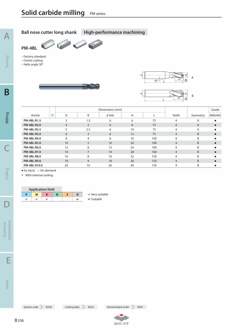
Ball nose cutter long shank High-performance machining
PM-4BL
– Factory standard – Centre cutting – Helix angle 30°
d
L H
D
10° R A
d
L H
D
R B
Dimensions [mm] Grade
Article D R d (h6) H L Teeth Geometry KMG405
PM-4BL-R1.5 3 1.5 6 6 75 4 A ● PM-4BL-R2.0 4 2 6 8 75 4 A ● PM-4BL-R2.5 5 2.5 6 10 75 4 A ● PM-4BL-R3.0 6 3 6 12 75 4 B ● PM-4BL-R4.0 8 4 8 16 100 4 B ● PM-4BL-R5.0 10 5 10 20 100 4 B ● PM-4BL-R6.0 12 6 12 24 100 4 B ● PM-4BL-R7.0 14 7 14 28 100 4 B ● PM-4BL-R8.0 16 8 16 32 150 4 B ● PM-4BL-R9.0 18 9 18 36 150 4 B ● PM-4BL-R10.0 20 10 20 40 150 4 B ●
● Ex stock ○ On demand With internal cooling
Application field P M K N S H
Very suitable Suitable
Solid carbide milling PM series
A
Turn
ing
B
Mill
ing
C
Dril
ling
D
Tech
nica
l In
form
atio
n
E
Inde
x
B 336
System code B258 Cutting data B422 Nonstandard order B461
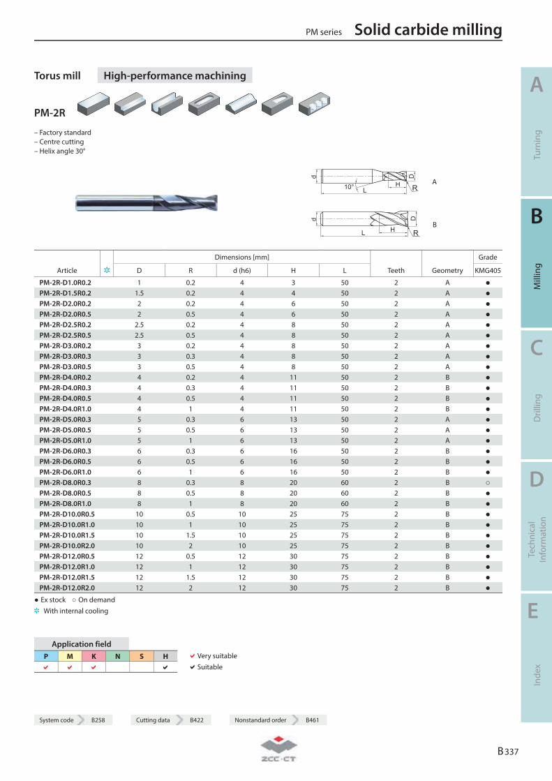
System code B258 Cutting data B422 Nonstandard order B461
Torus mill High-performance machining
PM-2R
– Factory standard – Centre cutting – Helix angle 30°
R A
R B
Dimensions [mm] Grade
Article D R d (h6) H L Teeth Geometry KMG405
PM-2R-D1.0R0.2 1 0.2 4 3 50 2 A ● PM-2R-D1.5R0.2 1.5 0.2 4 4 50 2 A ● PM-2R-D2.0R0.2 2 0.2 4 6 50 2 A ● PM-2R-D2.0R0.5 2 0.5 4 6 50 2 A ● PM-2R-D2.5R0.2 2.5 0.2 4 8 50 2 A ● PM-2R-D2.5R0.5 2.5 0.5 4 8 50 2 A ● PM-2R-D3.0R0.2 3 0.2 4 8 50 2 A ● PM-2R-D3.0R0.3 3 0.3 4 8 50 2 A ● PM-2R-D3.0R0.5 3 0.5 4 8 50 2 A ● PM-2R-D4.0R0.2 4 0.2 4 11 50 2 B ● PM-2R-D4.0R0.3 4 0.3 4 11 50 2 B ● PM-2R-D4.0R0.5 4 0.5 4 11 50 2 B ● PM-2R-D4.0R1.0 4 1 4 11 50 2 B ● PM-2R-D5.0R0.3 5 0.3 6 13 50 2 A ● PM-2R-D5.0R0.5 5 0.5 6 13 50 2 A ● PM-2R-D5.0R1.0 5 1 6 13 50 2 A ● PM-2R-D6.0R0.3 6 0.3 6 16 50 2 B ● PM-2R-D6.0R0.5 6 0.5 6 16 50 2 B ● PM-2R-D6.0R1.0 6 1 6 16 50 2 B ● PM-2R-D8.0R0.3 8 0.3 8 20 60 2 B ○ PM-2R-D8.0R0.5 8 0.5 8 20 60 2 B ● PM-2R-D8.0R1.0 8 1 8 20 60 2 B ● PM-2R-D10.0R0.5 10 0.5 10 25 75 2 B ● PM-2R-D10.0R1.0 10 1 10 25 75 2 B ● PM-2R-D10.0R1.5 10 1.5 10 25 75 2 B ● PM-2R-D10.0R2.0 10 2 10 25 75 2 B ● PM-2R-D12.0R0.5 12 0.5 12 30 75 2 B ● PM-2R-D12.0R1.0 12 1 12 30 75 2 B ● PM-2R-D12.0R1.5 12 1.5 12 30 75 2 B ● PM-2R-D12.0R2.0 12 2 12 30 75 2 B ●
● Ex stock ○ On demand With internal cooling
Application field P M K N S H
Very suitable Suitable
PM series Solid carbide milling
A
Turn
ing
B
Mill
ing
C
Dril
ling
D
Tech
nica
l In
form
atio
n
E
Inde
x
B 337
System code B258 Cutting data B422 Nonstandard order B461
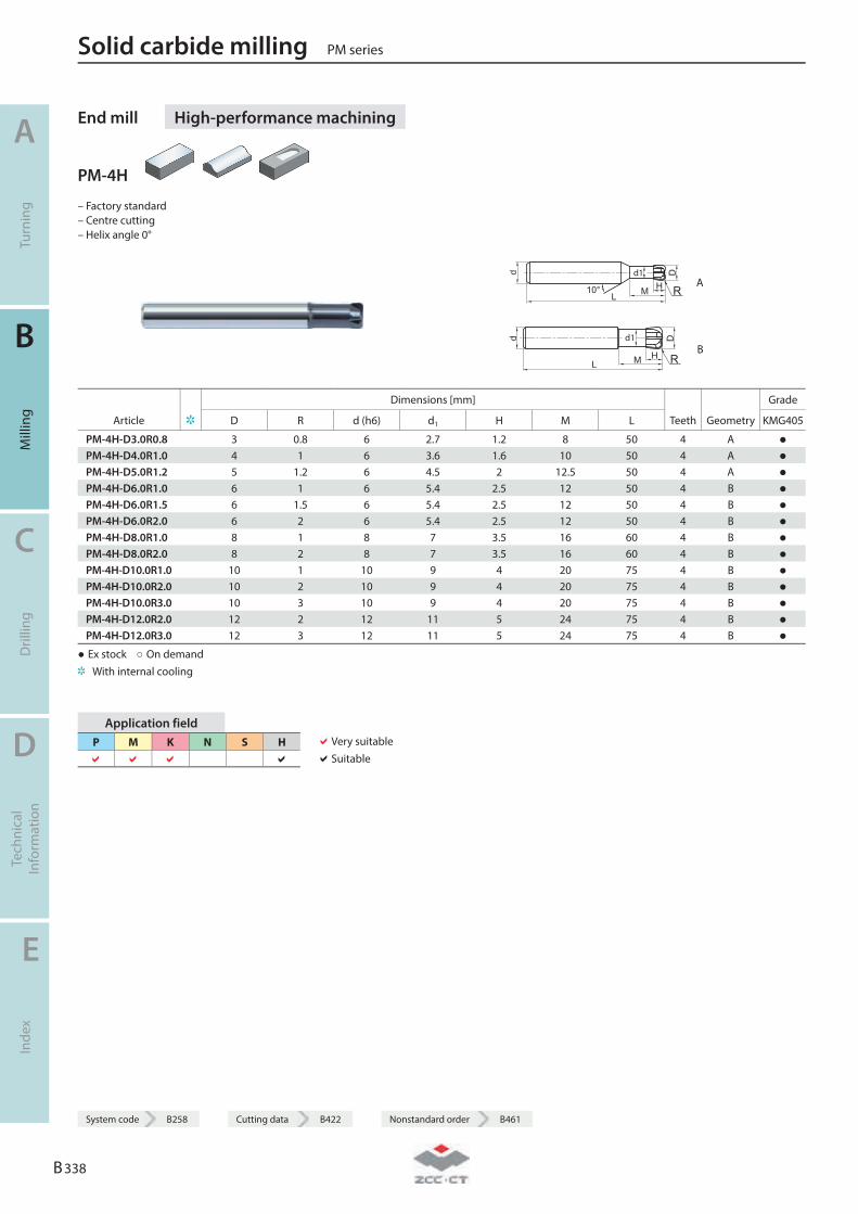
End mill High-performance machining
PM-4H
– Factory standard – Centre cutting – Helix angle 0°
d
L10° HM
Dd1
R A
d
LHM
Dd1
R B
Dimensions [mm] Grade
Article D R d (h6) d1 H M L Teeth Geometry KMG405
PM-4H-D3.0R0.8 3 0.8 6 2.7 1.2 8 50 4 A ● PM-4H-D4.0R1.0 4 1 6 3.6 1.6 10 50 4 A ● PM-4H-D5.0R1.2 5 1.2 6 4.5 2 12.5 50 4 A ● PM-4H-D6.0R1.0 6 1 6 5.4 2.5 12 50 4 B ● PM-4H-D6.0R1.5 6 1.5 6 5.4 2.5 12 50 4 B ● PM-4H-D6.0R2.0 6 2 6 5.4 2.5 12 50 4 B ● PM-4H-D8.0R1.0 8 1 8 7 3.5 16 60 4 B ● PM-4H-D8.0R2.0 8 2 8 7 3.5 16 60 4 B ● PM-4H-D10.0R1.0 10 1 10 9 4 20 75 4 B ● PM-4H-D10.0R2.0 10 2 10 9 4 20 75 4 B ● PM-4H-D10.0R3.0 10 3 10 9 4 20 75 4 B ● PM-4H-D12.0R2.0 12 2 12 11 5 24 75 4 B ● PM-4H-D12.0R3.0 12 3 12 11 5 24 75 4 B ●
● Ex stock ○ On demand With internal cooling
Application field P M K N S H
Very suitable Suitable
Solid carbide milling PM series
A
Turn
ing
B
Mill
ing
C
Dril
ling
D
Tech
nica
l In
form
atio
n
E
Inde
x
B 338
System code B258 Cutting data B422 Nonstandard order B461
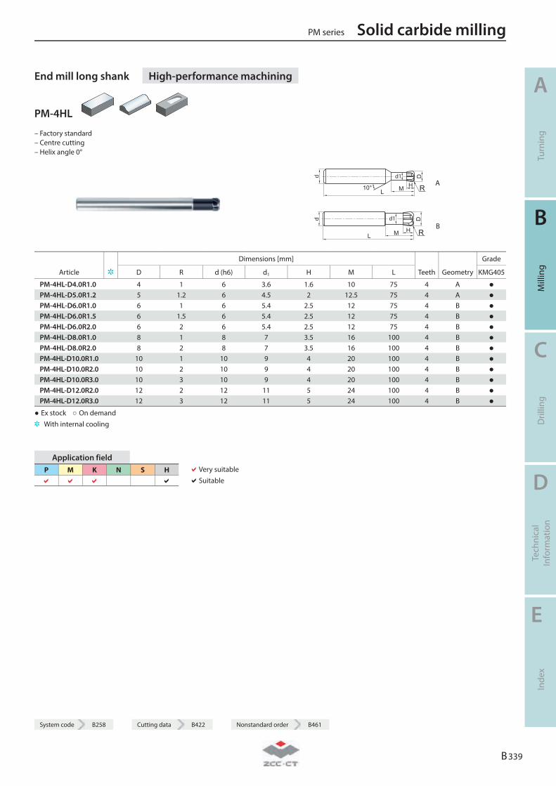
System code B258 Cutting data B422 Nonstandard order B461
End mill long shank High-performance machining
PM-4HL
– Factory standard – Centre cutting – Helix angle 0°
d
L10° HM
Dd1
R A
d
LHM
Dd1
R B
Dimensions [mm] Grade
Article D R d (h6) d1 H M L Teeth Geometry KMG405
PM-4HL-D4.0R1.0 4 1 6 3.6 1.6 10 75 4 A ● PM-4HL-D5.0R1.2 5 1.2 6 4.5 2 12.5 75 4 A ● PM-4HL-D6.0R1.0 6 1 6 5.4 2.5 12 75 4 B ● PM-4HL-D6.0R1.5 6 1.5 6 5.4 2.5 12 75 4 B ● PM-4HL-D6.0R2.0 6 2 6 5.4 2.5 12 75 4 B ● PM-4HL-D8.0R1.0 8 1 8 7 3.5 16 100 4 B ● PM-4HL-D8.0R2.0 8 2 8 7 3.5 16 100 4 B ● PM-4HL-D10.0R1.0 10 1 10 9 4 20 100 4 B ● PM-4HL-D10.0R2.0 10 2 10 9 4 20 100 4 B ● PM-4HL-D10.0R3.0 10 3 10 9 4 20 100 4 B ● PM-4HL-D12.0R2.0 12 2 12 11 5 24 100 4 B ● PM-4HL-D12.0R3.0 12 3 12 11 5 24 100 4 B ●
● Ex stock ○ On demand With internal cooling
Application field P M K N S H
Very suitable Suitable
PM series Solid carbide milling
A
Turn
ing
B
Mill
ing
C
Dril
ling
D
Tech
nica
l In
form
atio
n
E
Inde
x
B 339
System code B258 Cutting data B422 Nonstandard order B461
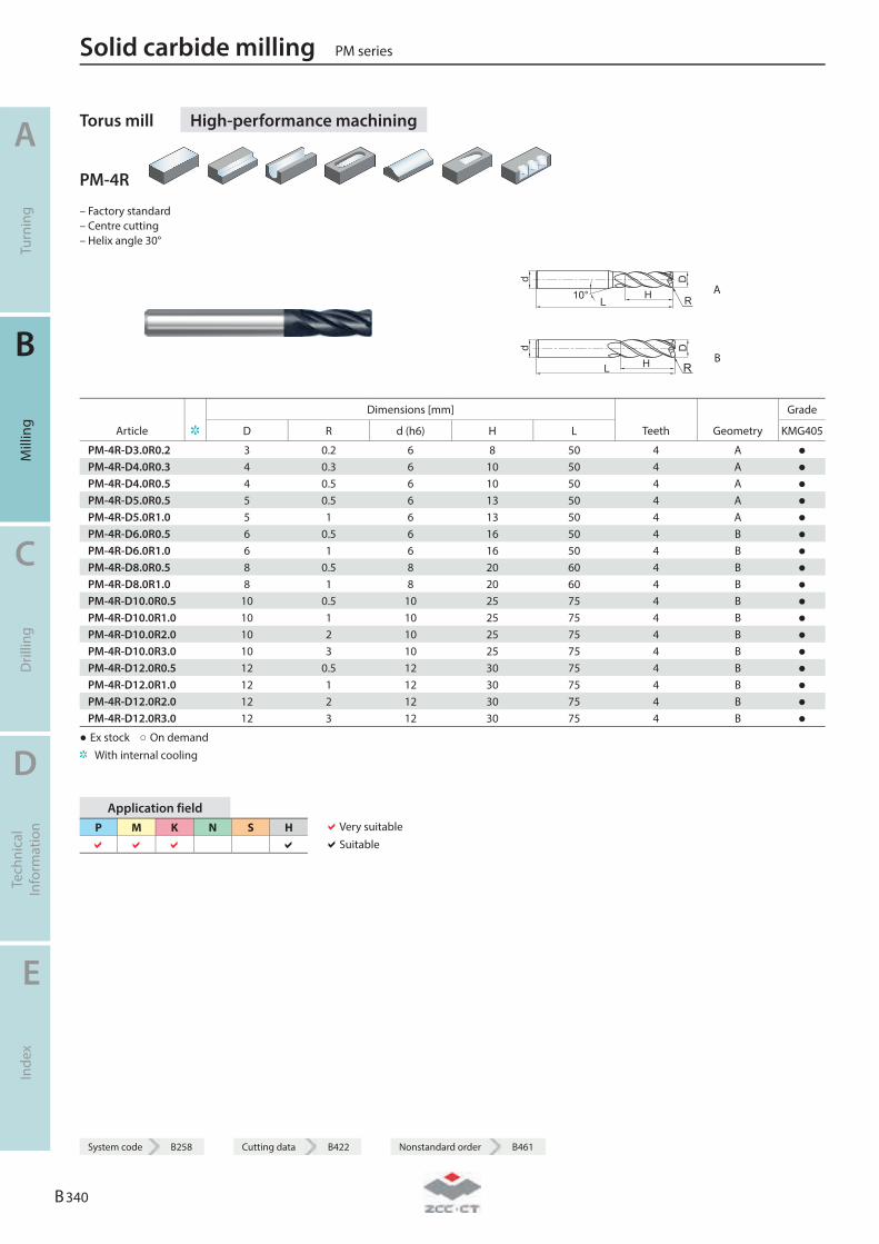
Torus mill High-performance machining
PM-4R
– Factory standard – Centre cutting – Helix angle 30°
R A
R B
Dimensions [mm] Grade
Article D R d (h6) H L Teeth Geometry KMG405
PM-4R-D3.0R0.2 3 0.2 6 8 50 4 A ● PM-4R-D4.0R0.3 4 0.3 6 10 50 4 A ● PM-4R-D4.0R0.5 4 0.5 6 10 50 4 A ● PM-4R-D5.0R0.5 5 0.5 6 13 50 4 A ● PM-4R-D5.0R1.0 5 1 6 13 50 4 A ● PM-4R-D6.0R0.5 6 0.5 6 16 50 4 B ● PM-4R-D6.0R1.0 6 1 6 16 50 4 B ● PM-4R-D8.0R0.5 8 0.5 8 20 60 4 B ● PM-4R-D8.0R1.0 8 1 8 20 60 4 B ● PM-4R-D10.0R0.5 10 0.5 10 25 75 4 B ● PM-4R-D10.0R1.0 10 1 10 25 75 4 B ● PM-4R-D10.0R2.0 10 2 10 25 75 4 B ● PM-4R-D10.0R3.0 10 3 10 25 75 4 B ● PM-4R-D12.0R0.5 12 0.5 12 30 75 4 B ● PM-4R-D12.0R1.0 12 1 12 30 75 4 B ● PM-4R-D12.0R2.0 12 2 12 30 75 4 B ● PM-4R-D12.0R3.0 12 3 12 30 75 4 B ●
● Ex stock ○ On demand With internal cooling
Application field P M K N S H
Very suitable Suitable
Solid carbide milling PM series
A
Turn
ing
B
Mill
ing
C
Dril
ling
D
Tech
nica
l In
form
atio
n
E
Inde
x
B 340
System code B258 Cutting data B422 Nonstandard order B461
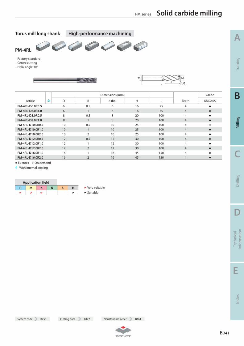
System code B258 Cutting data B422 Nonstandard order B461
Torus mill long shank High-performance machining
PM-4RL
– Factory standard – Centre cutting – Helix angle 30°
R
Dimensions [mm] Grade
Article D R d (h6) H L Teeth KMG405
PM-4RL-D6.0R0.5 6 0.5 6 16 75 4 ● PM-4RL-D6.0R1.0 6 1 6 16 75 4 ● PM-4RL-D8.0R0.5 8 0.5 8 20 100 4 ● PM-4RL-D8.0R1.0 8 1 8 20 100 4 ● PM-4RL-D10.0R0.5 10 0.5 10 25 100 4 ○ PM-4RL-D10.0R1.0 10 1 10 25 100 4 ● PM-4RL-D10.0R2.0 10 2 10 25 100 4 ● PM-4RL-D12.0R0.5 12 0.5 12 30 100 4 ● PM-4RL-D12.0R1.0 12 1 12 30 100 4 ● PM-4RL-D12.0R2.0 12 2 12 30 100 4 ● PM-4RL-D16.0R1.0 16 1 16 45 150 4 ● PM-4RL-D16.0R2.0 16 2 16 45 150 4 ●
● Ex stock ○ On demand With internal cooling
Application field P M K N S H
Very suitable Suitable
PM series Solid carbide milling
A
Turn
ing
B
Mill
ing
C
Dril
ling
D
Tech
nica
l In
form
atio
n
E
Inde
x
B 341
System code B258 Cutting data B422 Nonstandard order B461
Solid carbide milling PM series
A
Turn
ing
B
Mill
ing
C
Dril
ling
D
Tech
nica
l In
form
atio
n
E
Inde
x
B 342
Notes
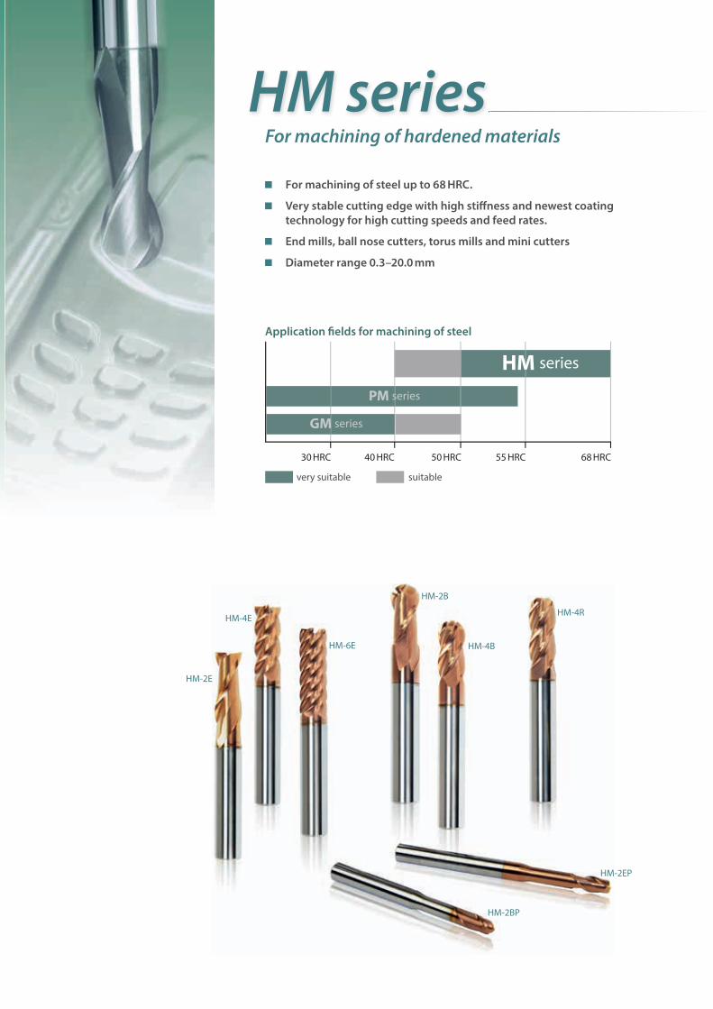
HM seriesFor machining of hardened materials
For machining of steel up to 68 HRC.
Very stable cutting edge with high stiff ness and newest coating technology for high cutting speeds and feed rates.
End mills, ball nose cutters, torus mills and mini cutters
Diameter range 0.3–20.0 mm
Application fi elds for machining of steel
30 HRC 40 HRC 50 HRC 55 HRC 68 HRC
very suitable suitable
HM series
PM series
GM series
HM-4E
HM-4B
HM-4R
HM-2EP
HM-2BP
HM-6E
HM-2E
HM-2B
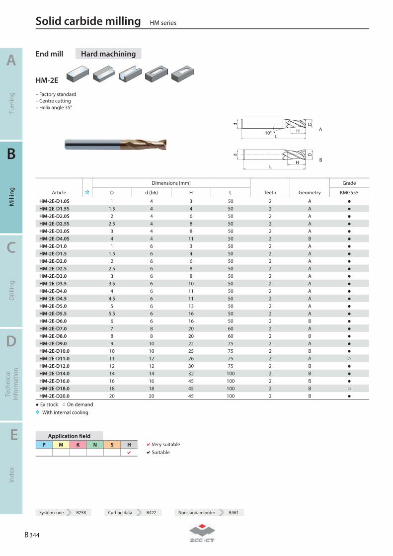
End mill Hard machining
HM-2E
– Factory standard – Centre cutting – Helix angle 35°
L
d
H
D
10° A
L
D
H
d
B
Dimensions [mm] Grade
Article D d (h6) H L Teeth Geometry KMG555
HM-2E-D1.0S 1 4 3 50 2 A ● HM-2E-D1.5S 1.5 4 4 50 2 A ● HM-2E-D2.0S 2 4 6 50 2 A ● HM-2E-D2.5S 2.5 4 8 50 2 A ● HM-2E-D3.0S 3 4 8 50 2 A ● HM-2E-D4.0S 4 4 11 50 2 B ● HM-2E-D1.0 1 6 3 50 2 A ● HM-2E-D1.5 1.5 6 4 50 2 A ● HM-2E-D2.0 2 6 6 50 2 A ● HM-2E-D2.5 2.5 6 8 50 2 A ● HM-2E-D3.0 3 6 8 50 2 A ● HM-2E-D3.5 3.5 6 10 50 2 A ● HM-2E-D4.0 4 6 11 50 2 A ● HM-2E-D4.5 4.5 6 11 50 2 A ● HM-2E-D5.0 5 6 13 50 2 A ● HM-2E-D5.5 5.5 6 16 50 2 A ● HM-2E-D6.0 6 6 16 50 2 B ● HM-2E-D7.0 7 8 20 60 2 A ● HM-2E-D8.0 8 8 20 60 2 B ● HM-2E-D9.0 9 10 22 75 2 A ● HM-2E-D10.0 10 10 25 75 2 B ● HM-2E-D11.0 11 12 26 75 2 A ○ HM-2E-D12.0 12 12 30 75 2 B ● HM-2E-D14.0 14 14 32 100 2 B ● HM-2E-D16.0 16 16 45 100 2 B ● HM-2E-D18.0 18 18 45 100 2 B ○ HM-2E-D20.0 20 20 45 100 2 B ●
● Ex stock ○ On demand With internal cooling
Application field P M K N S H
Very suitable Suitable
Solid carbide milling HM series
A
Turn
ing
B
Mill
ing
C
Dril
ling
D
Tech
nica
l In
form
atio
n
E
Inde
x
B 344
System code B258 Cutting data B422 Nonstandard order B461
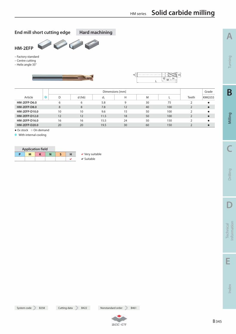
System code B258 Cutting data B422 Nonstandard order B461
End mill short cutting edge Hard machining
HM-2EFP
– Factory standard – Centre cutting – Helix angle 35°
Dimensions [mm] Grade
Article D d (h6) d1 H M L Teeth KMG555
HM-2EFP-D6.0 6 6 5.8 9 30 75 2 ● HM-2EFP-D8.0 8 8 7.8 12 40 100 2 ● HM-2EFP-D10.0 10 10 9.6 15 50 100 2 ● HM-2EFP-D12.0 12 12 11.5 18 50 100 2 ● HM-2EFP-D16.0 16 16 15.5 24 50 150 2 ● HM-2EFP-D20.0 20 20 19.5 30 60 150 2 ●
● Ex stock ○ On demand With internal cooling
Application field P M K N S H
Very suitable Suitable
HM series Solid carbide milling
A
Turn
ing
B
Mill
ing
C
Dril
ling
D
Tech
nica
l In
form
atio
n
E
Inde
x
B 345
System code B258 Cutting data B422 Nonstandard order B461
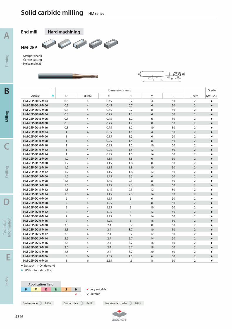
End mill Hard machining
HM-2EP
– Straight shank – Centre cutting – Helix angle 35°
L
D
H
d
d1 M10°
Dimensions [mm] Grade
Article D d (h6) d1 H M L Teeth KMG555
HM-2EP-D0.5-M04 0.5 4 0.45 0.7 4 50 2 ● HM-2EP-D0.5-M06 0.5 4 0.45 0.7 6 50 2 ● HM-2EP-D0.5-M08 0.5 4 0.45 0.7 8 50 2 ● HM-2EP-D0.8-M04 0.8 4 0.75 1.2 4 50 2 ● HM-2EP-D0.8-M06 0.8 4 0.75 1.2 6 50 2 ● HM-2EP-D0.8-M08 0.8 4 0.75 1.2 8 50 2 ● HM-2EP-D0.8-M10 0.8 4 0.75 1.2 10 50 2 ● HM-2EP-D1.0-M04 1 4 0.95 1.5 4 50 2 ● HM-2EP-D1.0-M06 1 4 0.95 1.5 6 50 2 ● HM-2EP-D1.0-M08 1 4 0.95 1.5 8 50 2 ● HM-2EP-D1.0-M10 1 4 0.95 1.5 10 50 2 ● HM-2EP-D1.0-M12 1 4 0.95 1.5 12 50 2 ● HM-2EP-D1.0-M14 1 4 0.95 1.5 14 50 2 ● HM-2EP-D1.2-M06 1.2 4 1.15 1.8 6 50 2 ● HM-2EP-D1.2-M08 1.2 4 1.15 1.8 8 50 2 ● HM-2EP-D1.2-M10 1.2 4 1.15 1.8 10 50 2 ● HM-2EP-D1.2-M12 1.2 4 1.15 1.8 12 50 2 ● HM-2EP-D1.5-M06 1.5 4 1.45 2.3 6 50 2 ● HM-2EP-D1.5-M08 1.5 4 1.45 2.3 8 50 2 ● HM-2EP-D1.5-M10 1.5 4 1.45 2.3 10 50 2 ● HM-2EP-D1.5-M12 1.5 4 1.45 2.3 12 50 2 ● HM-2EP-D1.5-M14 1.5 4 1.45 2.3 14 50 2 ● HM-2EP-D2.0-M06 2 4 1.95 3 6 50 2 ● HM-2EP-D2.0-M08 2 4 1.95 3 8 50 2 ● HM-2EP-D2.0-M10 2 4 1.95 3 10 50 2 ● HM-2EP-D2.0-M12 2 4 1.95 3 12 50 2 ● HM-2EP-D2.0-M14 2 4 1.95 3 14 50 2 ● HM-2EP-D2.0-M16 2 4 1.95 3 16 50 2 ● HM-2EP-D2.5-M08 2.5 4 2.4 3.7 8 50 2 ● HM-2EP-D2.5-M10 2.5 4 2.4 3.7 10 50 2 ● HM-2EP-D2.5-M12 2.5 4 2.4 3.7 12 50 2 ● HM-2EP-D2.5-M14 2.5 4 2.4 3.7 14 50 2 ● HM-2EP-D2.5-M16 2.5 4 2.4 3.7 16 60 2 ● HM-2EP-D2.5-M18 2.5 4 2.4 3.7 18 60 2 ● HM-2EP-D2.5-M20 2.5 4 2.4 3.7 20 60 2 ● HM-2EP-D3.0-M06 3 6 2.85 4.5 6 50 2 ● HM-2EP-D3.0-M08 3 6 2.85 4.5 8 50 2 ●
● Ex stock ○ On demand With internal cooling
Application field P M K N S H
Very suitable Suitable
Solid carbide milling HM series
A
Turn
ing
B
Mill
ing
C
Dril
ling
D
Tech
nica
l In
form
atio
n
E
Inde
x
B 346
System code B258 Cutting data B422 Nonstandard order B461
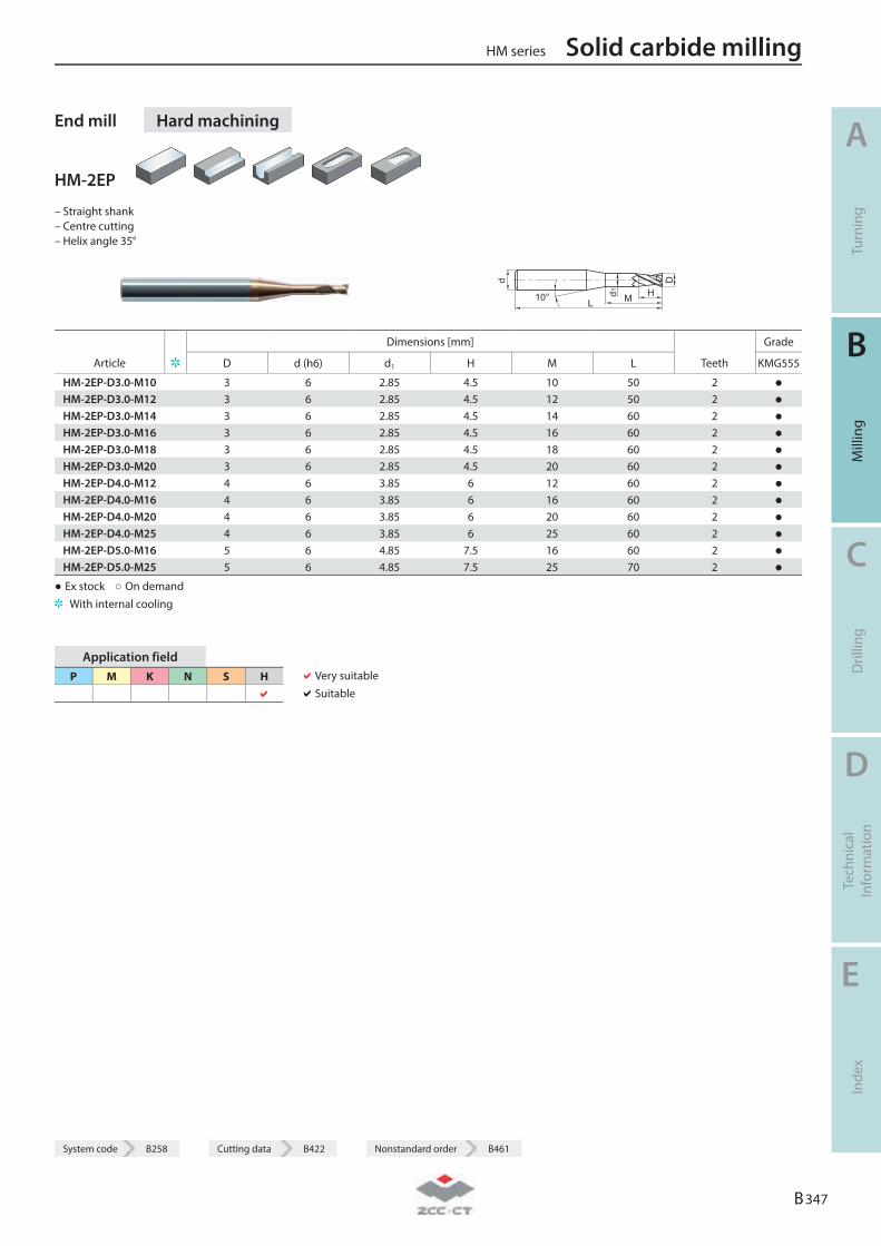
System code B258 Cutting data B422 Nonstandard order B461
End mill Hard machining
HM-2EP
– Straight shank – Centre cutting – Helix angle 35°
L
D
H
d
d1 M10°
Dimensions [mm] Grade
Article D d (h6) d1 H M L Teeth KMG555
HM-2EP-D3.0-M10 3 6 2.85 4.5 10 50 2 ● HM-2EP-D3.0-M12 3 6 2.85 4.5 12 50 2 ● HM-2EP-D3.0-M14 3 6 2.85 4.5 14 60 2 ● HM-2EP-D3.0-M16 3 6 2.85 4.5 16 60 2 ● HM-2EP-D3.0-M18 3 6 2.85 4.5 18 60 2 ● HM-2EP-D3.0-M20 3 6 2.85 4.5 20 60 2 ● HM-2EP-D4.0-M12 4 6 3.85 6 12 60 2 ● HM-2EP-D4.0-M16 4 6 3.85 6 16 60 2 ● HM-2EP-D4.0-M20 4 6 3.85 6 20 60 2 ● HM-2EP-D4.0-M25 4 6 3.85 6 25 60 2 ● HM-2EP-D5.0-M16 5 6 4.85 7.5 16 60 2 ● HM-2EP-D5.0-M25 5 6 4.85 7.5 25 70 2 ●
● Ex stock ○ On demand With internal cooling
Application field P M K N S H
Very suitable Suitable
HM series Solid carbide milling
A
Turn
ing
B
Mill
ing
C
Dril
ling
D
Tech
nica
l In
form
atio
n
E
Inde
x
B 347
System code B258 Cutting data B422 Nonstandard order B461

End mill Hard machining
HM-2ES
– Factory standard – Centre cutting – Helix angle 35°
L
D
H
d
10°
Dimensions [mm] Grade
Article D d (h6) H L Teeth KMG555
HM-2ES-D0.3 0.3 4 0.6 50 2 ● HM-2ES-D0.4 0.4 4 0.8 50 2 ● HM-2ES-D0.5 0.5 4 1 50 2 ● HM-2ES-D0.6 0.6 4 1.2 50 2 ● HM-2ES-D0.7 0.7 4 1.4 50 2 ● HM-2ES-D0.8 0.8 4 1.6 50 2 ● HM-2ES-D0.9 0.9 4 1.8 50 2 ● HM-2ES-D1.0 1 4 2 50 2 ● HM-2ES-D1.1 1.1 4 2 50 2 ● HM-2ES-D1.2 1.2 4 2.5 50 2 ● HM-2ES-D1.3 1.3 4 2.5 50 2 ● HM-2ES-D1.4 1.4 4 3 50 2 ● HM-2ES-D1.5 1.5 4 3 50 2 ● HM-2ES-D1.6 1.6 4 3.5 50 2 ● HM-2ES-D1.7 1.7 4 3.5 50 2 ● HM-2ES-D1.8 1.8 4 4 50 2 ● HM-2ES-D1.9 1.9 4 4 50 2 ● HM-2ES-D2.0 2 4 4 50 2 ● HM-2ES-D2.1 2.1 4 4 50 2 ● HM-2ES-D2.2 2.2 4 4.5 50 2 ● HM-2ES-D2.3 2.3 4 4.5 50 2 ● HM-2ES-D2.4 2.4 4 5 50 2 ● HM-2ES-D2.5 2.5 4 5 50 2 ● HM-2ES-D2.6 2.6 4 5 50 2 ● HM-2ES-D2.7 2.7 4 5.5 50 2 ● HM-2ES-D2.8 2.8 4 5.5 50 2 ● HM-2ES-D2.9 2.9 4 6 50 2 ● HM-2ES-D3.0 3 4 6 50 2 ●
● Ex stock ○ On demand With internal cooling
Application field P M K N S H
Very suitable Suitable
Solid carbide milling HM series
A
Turn
ing
B
Mill
ing
C
Dril
ling
D
Tech
nica
l In
form
atio
n
E
Inde
x
B 348
System code B258 Cutting data B422 Nonstandard order B461
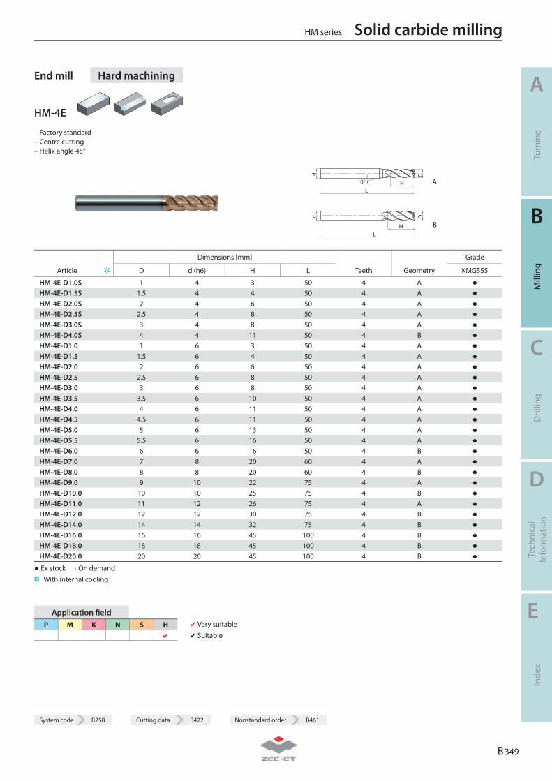
System code B258 Cutting data B422 Nonstandard order B461
End mill Hard machining
HM-4E
– Factory standard – Centre cutting – Helix angle 45°
L
D
H10°
d
A
LH
Dd
B
Dimensions [mm] Grade
Article D d (h6) H L Teeth Geometry KMG555
HM-4E-D1.0S 1 4 3 50 4 A ● HM-4E-D1.5S 1.5 4 4 50 4 A ● HM-4E-D2.0S 2 4 6 50 4 A ● HM-4E-D2.5S 2.5 4 8 50 4 A ● HM-4E-D3.0S 3 4 8 50 4 A ● HM-4E-D4.0S 4 4 11 50 4 B ● HM-4E-D1.0 1 6 3 50 4 A ● HM-4E-D1.5 1.5 6 4 50 4 A ● HM-4E-D2.0 2 6 6 50 4 A ● HM-4E-D2.5 2.5 6 8 50 4 A ● HM-4E-D3.0 3 6 8 50 4 A ● HM-4E-D3.5 3.5 6 10 50 4 A ● HM-4E-D4.0 4 6 11 50 4 A ● HM-4E-D4.5 4.5 6 11 50 4 A ● HM-4E-D5.0 5 6 13 50 4 A ● HM-4E-D5.5 5.5 6 16 50 4 A ● HM-4E-D6.0 6 6 16 50 4 B ● HM-4E-D7.0 7 8 20 60 4 A ● HM-4E-D8.0 8 8 20 60 4 B ● HM-4E-D9.0 9 10 22 75 4 A ● HM-4E-D10.0 10 10 25 75 4 B ● HM-4E-D11.0 11 12 26 75 4 A ● HM-4E-D12.0 12 12 30 75 4 B ● HM-4E-D14.0 14 14 32 75 4 B ● HM-4E-D16.0 16 16 45 100 4 B ● HM-4E-D18.0 18 18 45 100 4 B ● HM-4E-D20.0 20 20 45 100 4 B ●
● Ex stock ○ On demand With internal cooling
Application field P M K N S H
Very suitable Suitable
HM series Solid carbide milling
A
Turn
ing
B
Mill
ing
C
Dril
ling
D
Tech
nica
l In
form
atio
n
E
Inde
x
B 349
System code B258 Cutting data B422 Nonstandard order B461
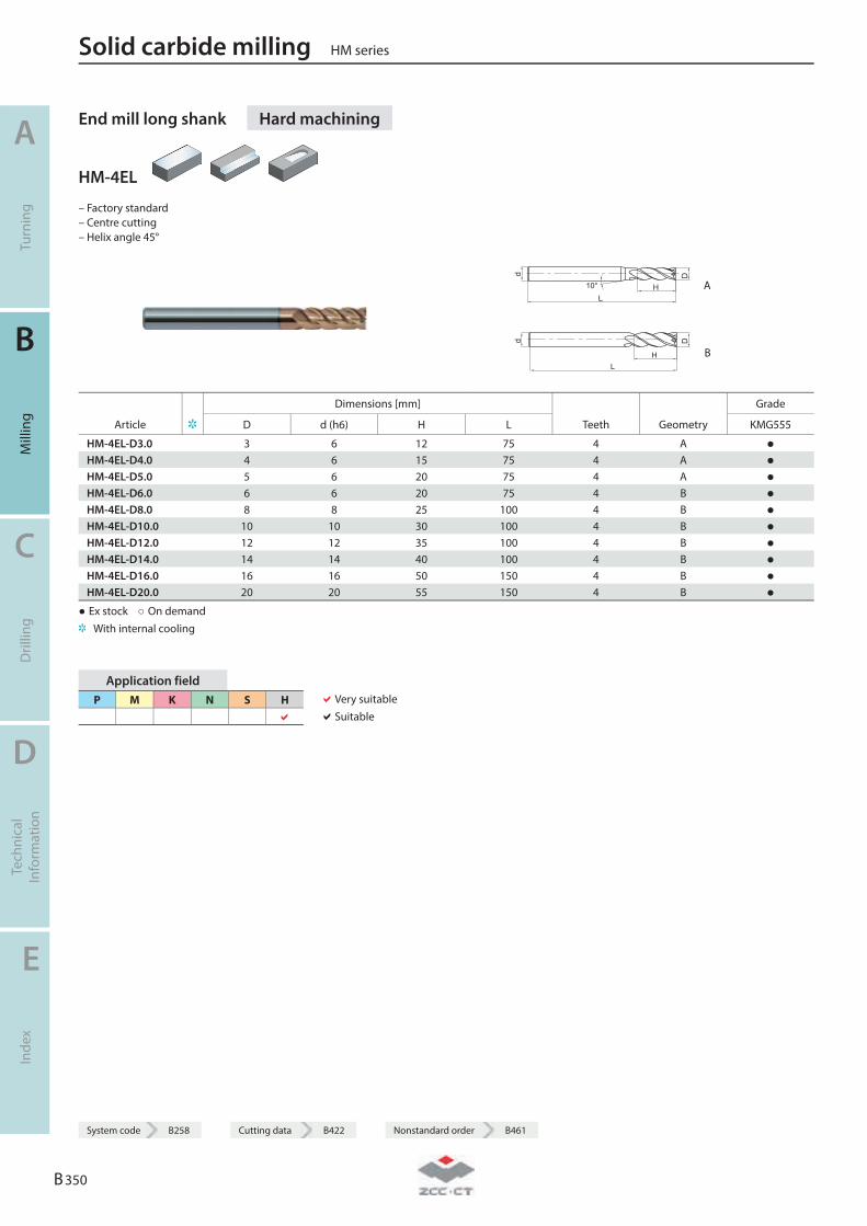
End mill long shank Hard machining
HM-4EL
– Factory standard – Centre cutting – Helix angle 45°
L
D
H10°
d
A
LH
Dd
B
Dimensions [mm] Grade
Article D d (h6) H L Teeth Geometry KMG555
HM-4EL-D3.0 3 6 12 75 4 A ● HM-4EL-D4.0 4 6 15 75 4 A ● HM-4EL-D5.0 5 6 20 75 4 A ● HM-4EL-D6.0 6 6 20 75 4 B ● HM-4EL-D8.0 8 8 25 100 4 B ● HM-4EL-D10.0 10 10 30 100 4 B ● HM-4EL-D12.0 12 12 35 100 4 B ● HM-4EL-D14.0 14 14 40 100 4 B ● HM-4EL-D16.0 16 16 50 150 4 B ● HM-4EL-D20.0 20 20 55 150 4 B ●
● Ex stock ○ On demand With internal cooling
Application field P M K N S H
Very suitable Suitable
Solid carbide milling HM series
A
Turn
ing
B
Mill
ing
C
Dril
ling
D
Tech
nica
l In
form
atio
n
E
Inde
x
B 350
System code B258 Cutting data B422 Nonstandard order B461
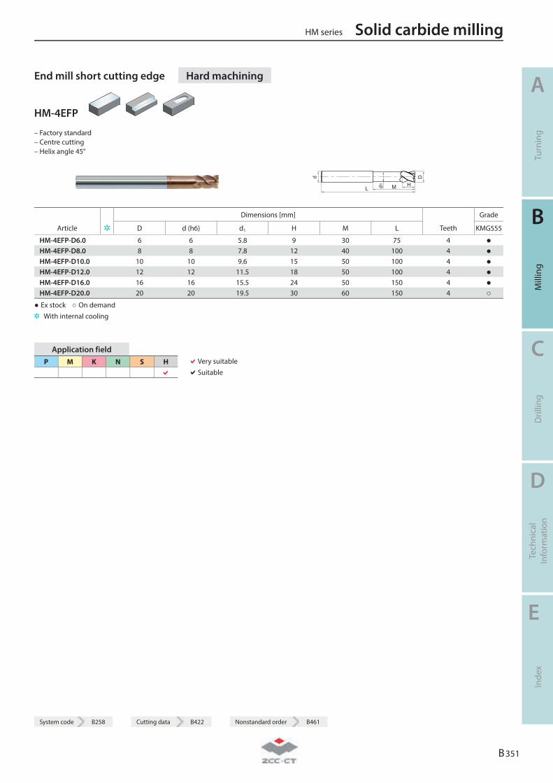
System code B258 Cutting data B422 Nonstandard order B461
End mill short cutting edge Hard machining
HM-4EFP
– Factory standard – Centre cutting – Helix angle 45°
d
L d1 HM
D
Dimensions [mm] Grade
Article D d (h6) d1 H M L Teeth KMG555
HM-4EFP-D6.0 6 6 5.8 9 30 75 4 ● HM-4EFP-D8.0 8 8 7.8 12 40 100 4 ● HM-4EFP-D10.0 10 10 9.6 15 50 100 4 ● HM-4EFP-D12.0 12 12 11.5 18 50 100 4 ● HM-4EFP-D16.0 16 16 15.5 24 50 150 4 ● HM-4EFP-D20.0 20 20 19.5 30 60 150 4 ○
● Ex stock ○ On demand With internal cooling
Application field P M K N S H
Very suitable Suitable
HM series Solid carbide milling
A
Turn
ing
B
Mill
ing
C
Dril
ling
D
Tech
nica
l In
form
atio
n
E
Inde
x
B 351
System code B258 Cutting data B422 Nonstandard order B461
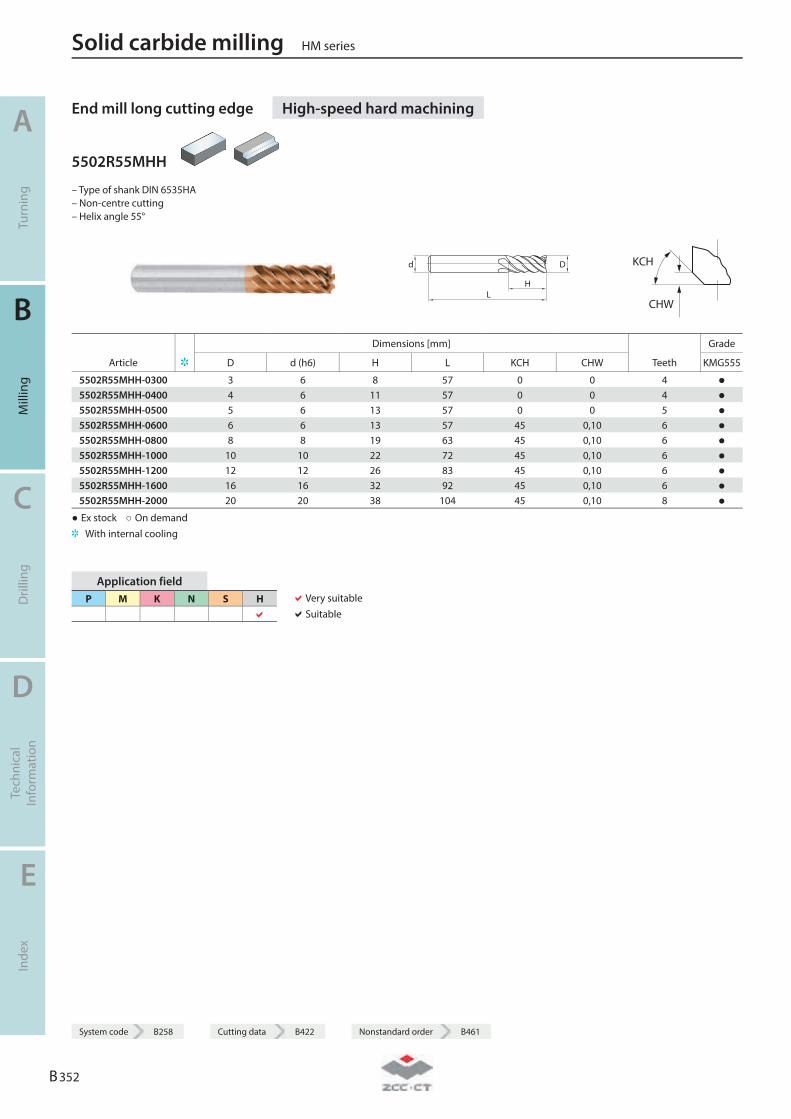
End mill long cutting edge High-speed hard machining
5502R55MHH
– Type of shank DIN 6535HA – Non-centre cutting – Helix angle 55°
LH
Dd
KCH
CHW
Dimensions [mm] Grade
Article D d (h6) H L KCH CHW Teeth KMG555
5502R55MHH-0300 3 6 8 57 0 0 4 ● 5502R55MHH-0400 4 6 11 57 0 0 4 ● 5502R55MHH-0500 5 6 13 57 0 0 5 ● 5502R55MHH-0600 6 6 13 57 45 0,10 6 ● 5502R55MHH-0800 8 8 19 63 45 0,10 6 ● 5502R55MHH-1000 10 10 22 72 45 0,10 6 ● 5502R55MHH-1200 12 12 26 83 45 0,10 6 ● 5502R55MHH-1600 16 16 32 92 45 0,10 6 ● 5502R55MHH-2000 20 20 38 104 45 0,10 8 ●
● Ex stock ○ On demand With internal cooling
Application field P M K N S H
Very suitable Suitable
Solid carbide milling HM series
A
Turn
ing
B
Mill
ing
C
Dril
ling
D
Tech
nica
l In
form
atio
n
E
Inde
x
B 352
System code B258 Cutting data B422 Nonstandard order B461
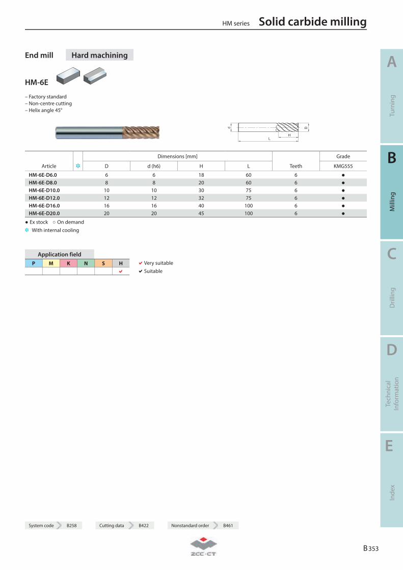
System code B258 Cutting data B422 Nonstandard order B461
End mill Hard machining
HM-6E
– Factory standard – Non-centre cutting – Helix angle 45°
L
D
H
d
Dimensions [mm] Grade
Article D d (h6) H L Teeth KMG555
HM-6E-D6.0 6 6 18 60 6 ● HM-6E-D8.0 8 8 20 60 6 ● HM-6E-D10.0 10 10 30 75 6 ● HM-6E-D12.0 12 12 32 75 6 ● HM-6E-D16.0 16 16 40 100 6 ● HM-6E-D20.0 20 20 45 100 6 ●
● Ex stock ○ On demand With internal cooling
Application field P M K N S H
Very suitable Suitable
HM series Solid carbide milling
A
Turn
ing
B
Mill
ing
C
Dril
ling
D
Tech
nica
l In
form
atio
n
E
Inde
x
B 353
System code B258 Cutting data B422 Nonstandard order B461
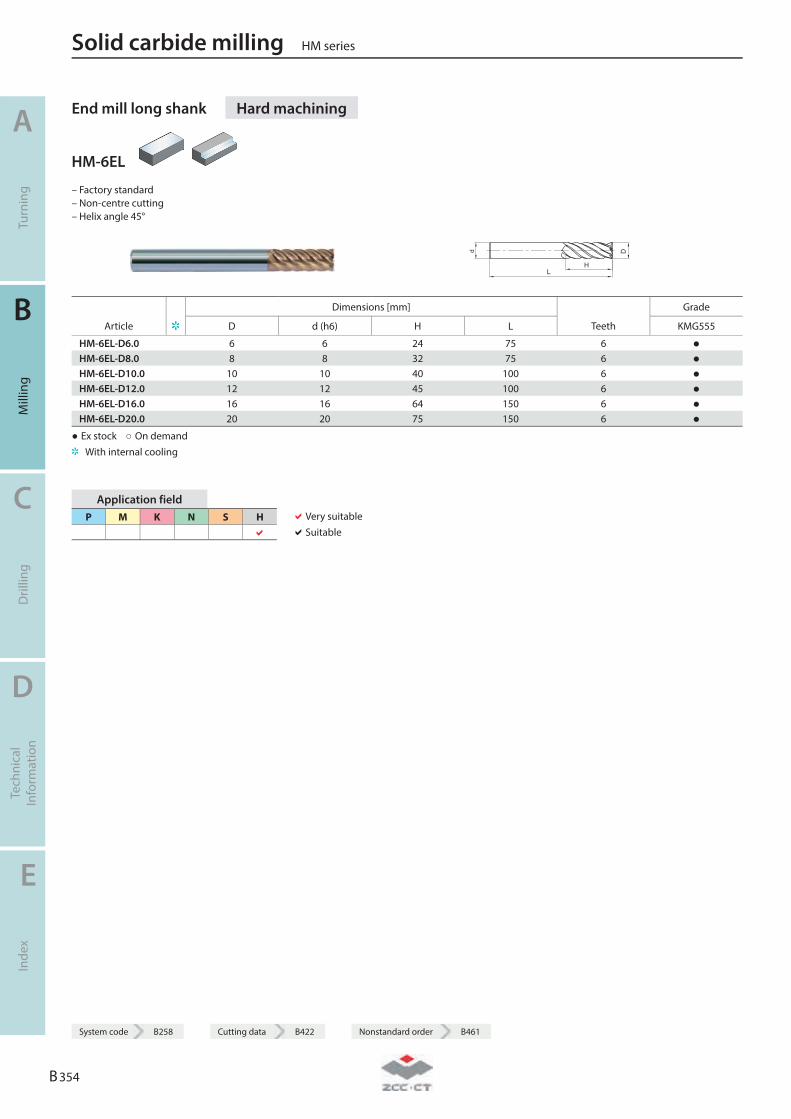
End mill long shank Hard machining
HM-6EL
– Factory standard – Non-centre cutting – Helix angle 45°
L
D
H
d
Dimensions [mm] Grade
Article D d (h6) H L Teeth KMG555
HM-6EL-D6.0 6 6 24 75 6 ● HM-6EL-D8.0 8 8 32 75 6 ● HM-6EL-D10.0 10 10 40 100 6 ● HM-6EL-D12.0 12 12 45 100 6 ● HM-6EL-D16.0 16 16 64 150 6 ● HM-6EL-D20.0 20 20 75 150 6 ●
● Ex stock ○ On demand With internal cooling
Application field P M K N S H
Very suitable Suitable
Solid carbide milling HM series
A
Turn
ing
B
Mill
ing
C
Dril
ling
D
Tech
nica
l In
form
atio
n
E
Inde
x
B 354
System code B258 Cutting data B422 Nonstandard order B461
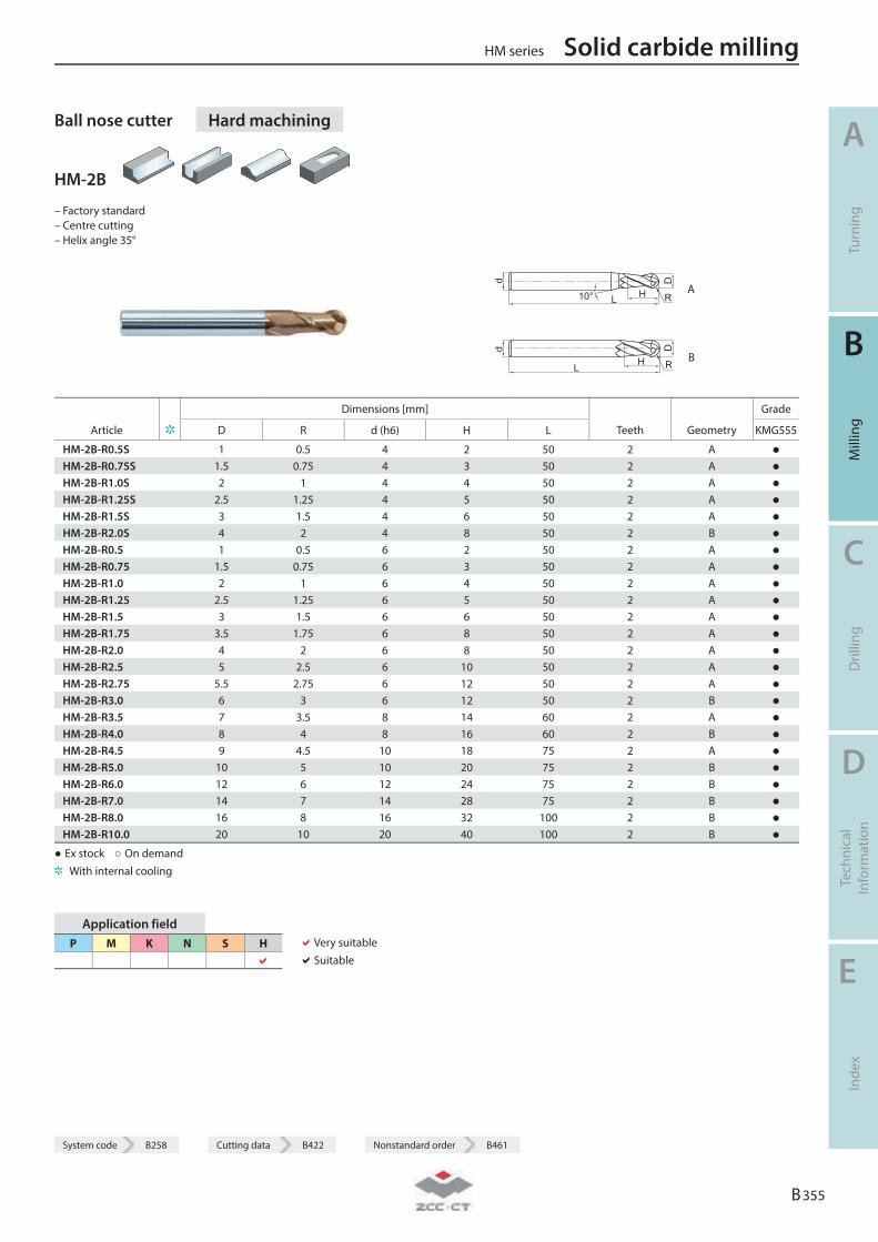
System code B258 Cutting data B422 Nonstandard order B461
Ball nose cutter Hard machining
HM-2B
– Factory standard – Centre cutting – Helix angle 35°
R A
R B
Dimensions [mm] Grade
Article D R d (h6) H L Teeth Geometry KMG555
HM-2B-R0.5S 1 0.5 4 2 50 2 A ● HM-2B-R0.75S 1.5 0.75 4 3 50 2 A ● HM-2B-R1.0S 2 1 4 4 50 2 A ● HM-2B-R1.25S 2.5 1.25 4 5 50 2 A ● HM-2B-R1.5S 3 1.5 4 6 50 2 A ● HM-2B-R2.0S 4 2 4 8 50 2 B ● HM-2B-R0.5 1 0.5 6 2 50 2 A ● HM-2B-R0.75 1.5 0.75 6 3 50 2 A ● HM-2B-R1.0 2 1 6 4 50 2 A ● HM-2B-R1.25 2.5 1.25 6 5 50 2 A ● HM-2B-R1.5 3 1.5 6 6 50 2 A ● HM-2B-R1.75 3.5 1.75 6 8 50 2 A ● HM-2B-R2.0 4 2 6 8 50 2 A ● HM-2B-R2.5 5 2.5 6 10 50 2 A ● HM-2B-R2.75 5.5 2.75 6 12 50 2 A ● HM-2B-R3.0 6 3 6 12 50 2 B ● HM-2B-R3.5 7 3.5 8 14 60 2 A ● HM-2B-R4.0 8 4 8 16 60 2 B ● HM-2B-R4.5 9 4.5 10 18 75 2 A ● HM-2B-R5.0 10 5 10 20 75 2 B ● HM-2B-R6.0 12 6 12 24 75 2 B ● HM-2B-R7.0 14 7 14 28 75 2 B ● HM-2B-R8.0 16 8 16 32 100 2 B ● HM-2B-R10.0 20 10 20 40 100 2 B ●
● Ex stock ○ On demand With internal cooling
Application field P M K N S H
Very suitable Suitable
HM series Solid carbide milling
A
Turn
ing
B
Mill
ing
C
Dril
ling
D
Tech
nica
l In
form
atio
n
E
Inde
x
B 355
System code B258 Cutting data B422 Nonstandard order B461
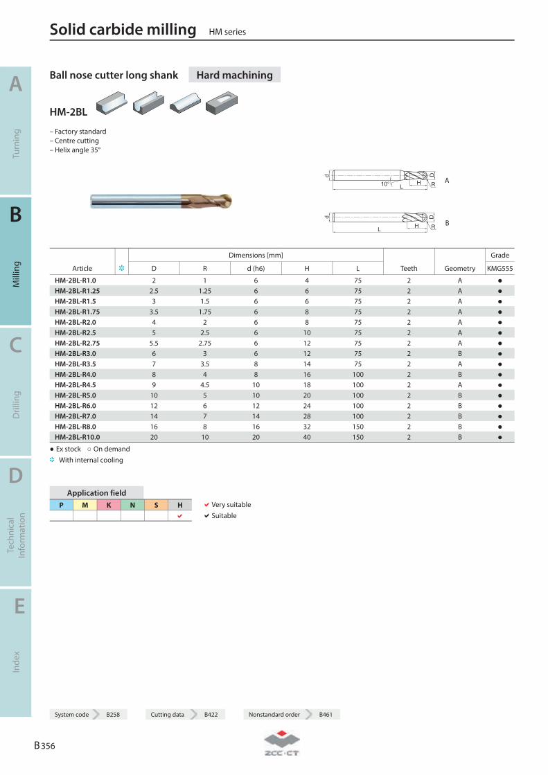
Ball nose cutter long shank Hard machining
HM-2BL
– Factory standard – Centre cutting – Helix angle 35°
R A
R B
Dimensions [mm] Grade
Article D R d (h6) H L Teeth Geometry KMG555
HM-2BL-R1.0 2 1 6 4 75 2 A ● HM-2BL-R1.25 2.5 1.25 6 6 75 2 A ● HM-2BL-R1.5 3 1.5 6 6 75 2 A ● HM-2BL-R1.75 3.5 1.75 6 8 75 2 A ● HM-2BL-R2.0 4 2 6 8 75 2 A ● HM-2BL-R2.5 5 2.5 6 10 75 2 A ● HM-2BL-R2.75 5.5 2.75 6 12 75 2 A ● HM-2BL-R3.0 6 3 6 12 75 2 B ● HM-2BL-R3.5 7 3.5 8 14 75 2 A ● HM-2BL-R4.0 8 4 8 16 100 2 B ● HM-2BL-R4.5 9 4.5 10 18 100 2 A ● HM-2BL-R5.0 10 5 10 20 100 2 B ● HM-2BL-R6.0 12 6 12 24 100 2 B ● HM-2BL-R7.0 14 7 14 28 100 2 B ● HM-2BL-R8.0 16 8 16 32 150 2 B ● HM-2BL-R10.0 20 10 20 40 150 2 B ●
● Ex stock ○ On demand With internal cooling
Application field P M K N S H
Very suitable Suitable
Solid carbide milling HM series
A
Turn
ing
B
Mill
ing
C
Dril
ling
D
Tech
nica
l In
form
atio
n
E
Inde
x
B 356
System code B258 Cutting data B422 Nonstandard order B461
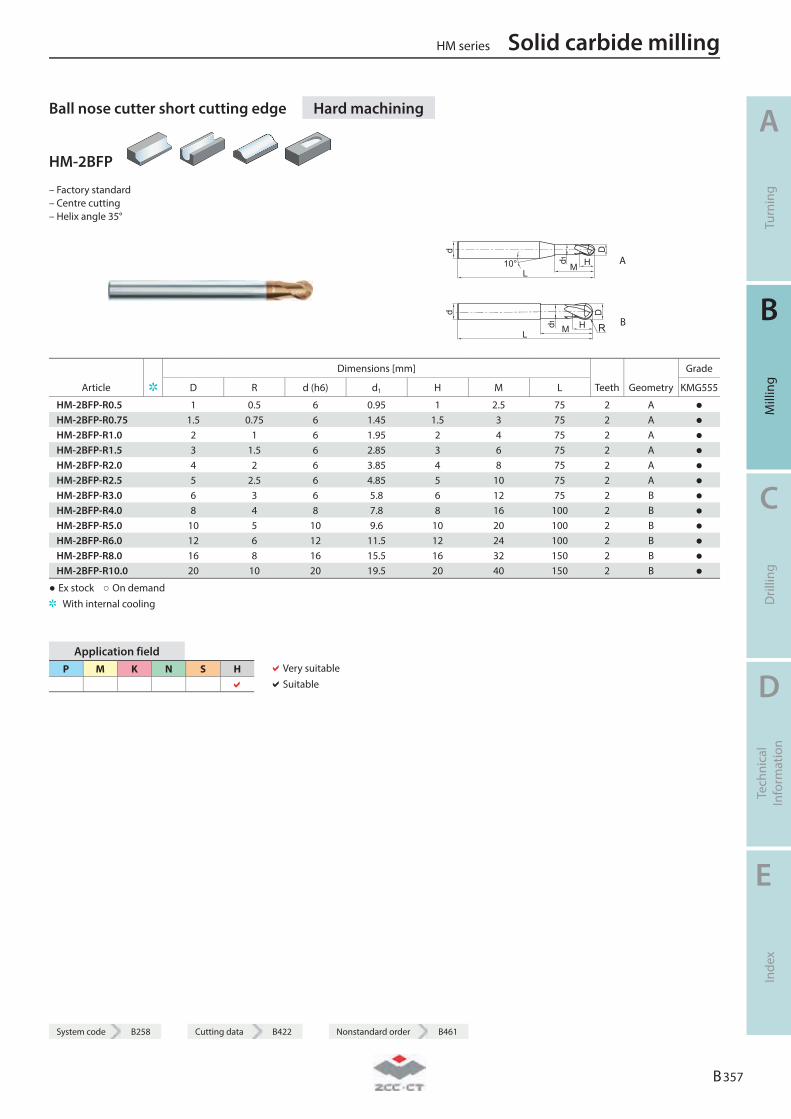
System code B258 Cutting data B422 Nonstandard order B461
Ball nose cutter short cutting edge Hard machining
HM-2BFP
– Factory standard – Centre cutting – Helix angle 35°
A
R B
Dimensions [mm] Grade
Article D R d (h6) d1 H M L Teeth Geometry KMG555
HM-2BFP-R0.5 1 0.5 6 0.95 1 2.5 75 2 A ● HM-2BFP-R0.75 1.5 0.75 6 1.45 1.5 3 75 2 A ● HM-2BFP-R1.0 2 1 6 1.95 2 4 75 2 A ● HM-2BFP-R1.5 3 1.5 6 2.85 3 6 75 2 A ● HM-2BFP-R2.0 4 2 6 3.85 4 8 75 2 A ● HM-2BFP-R2.5 5 2.5 6 4.85 5 10 75 2 A ● HM-2BFP-R3.0 6 3 6 5.8 6 12 75 2 B ● HM-2BFP-R4.0 8 4 8 7.8 8 16 100 2 B ● HM-2BFP-R5.0 10 5 10 9.6 10 20 100 2 B ● HM-2BFP-R6.0 12 6 12 11.5 12 24 100 2 B ● HM-2BFP-R8.0 16 8 16 15.5 16 32 150 2 B ● HM-2BFP-R10.0 20 10 20 19.5 20 40 150 2 B ●
● Ex stock ○ On demand With internal cooling
Application field P M K N S H
Very suitable Suitable
HM series Solid carbide milling
A
Turn
ing
B
Mill
ing
C
Dril
ling
D
Tech
nica
l In
form
atio
n
E
Inde
x
B 357
System code B258 Cutting data B422 Nonstandard order B461
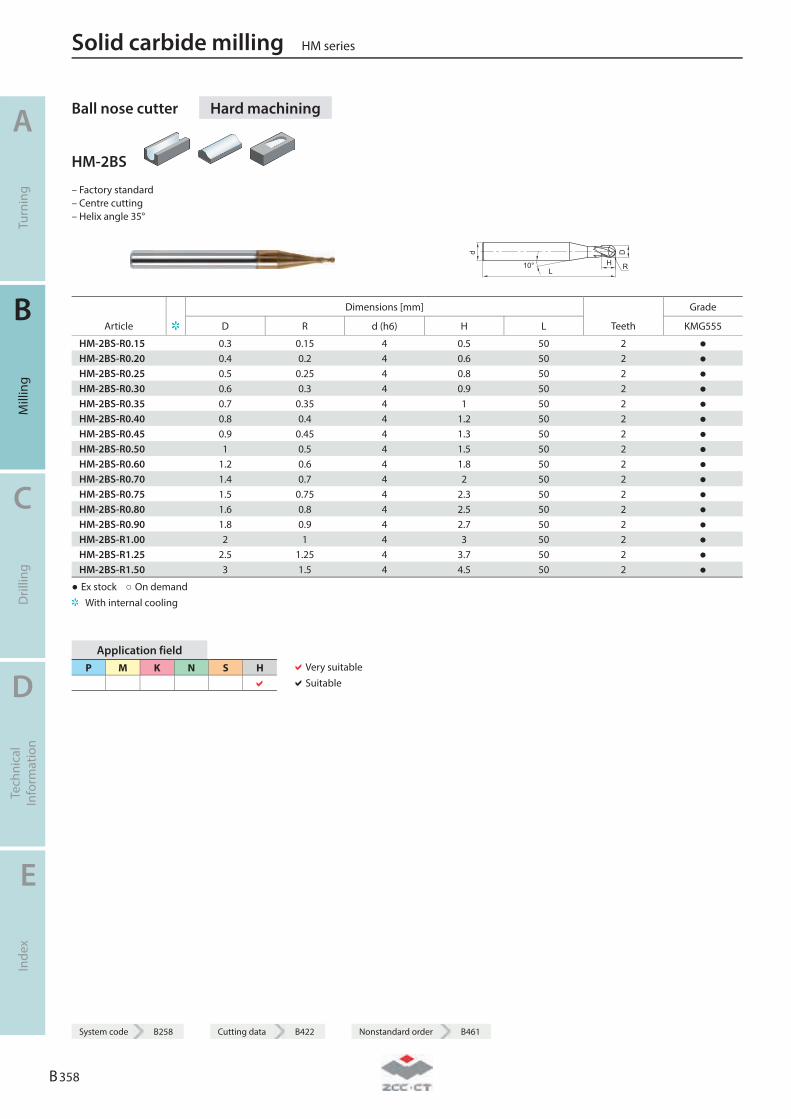
Ball nose cutter Hard machining
HM-2BS
– Factory standard – Centre cutting – Helix angle 35°
L
D
H
d
10° R
Dimensions [mm] Grade
Article D R d (h6) H L Teeth KMG555
HM-2BS-R0.15 0.3 0.15 4 0.5 50 2 ● HM-2BS-R0.20 0.4 0.2 4 0.6 50 2 ● HM-2BS-R0.25 0.5 0.25 4 0.8 50 2 ● HM-2BS-R0.30 0.6 0.3 4 0.9 50 2 ● HM-2BS-R0.35 0.7 0.35 4 1 50 2 ● HM-2BS-R0.40 0.8 0.4 4 1.2 50 2 ● HM-2BS-R0.45 0.9 0.45 4 1.3 50 2 ● HM-2BS-R0.50 1 0.5 4 1.5 50 2 ● HM-2BS-R0.60 1.2 0.6 4 1.8 50 2 ● HM-2BS-R0.70 1.4 0.7 4 2 50 2 ● HM-2BS-R0.75 1.5 0.75 4 2.3 50 2 ● HM-2BS-R0.80 1.6 0.8 4 2.5 50 2 ● HM-2BS-R0.90 1.8 0.9 4 2.7 50 2 ● HM-2BS-R1.00 2 1 4 3 50 2 ● HM-2BS-R1.25 2.5 1.25 4 3.7 50 2 ● HM-2BS-R1.50 3 1.5 4 4.5 50 2 ●
● Ex stock ○ On demand With internal cooling
Application field P M K N S H
Very suitable Suitable
Solid carbide milling HM series
A
Turn
ing
B
Mill
ing
C
Dril
ling
D
Tech
nica
l In
form
atio
n
E
Inde
x
B 358
System code B258 Cutting data B422 Nonstandard order B461
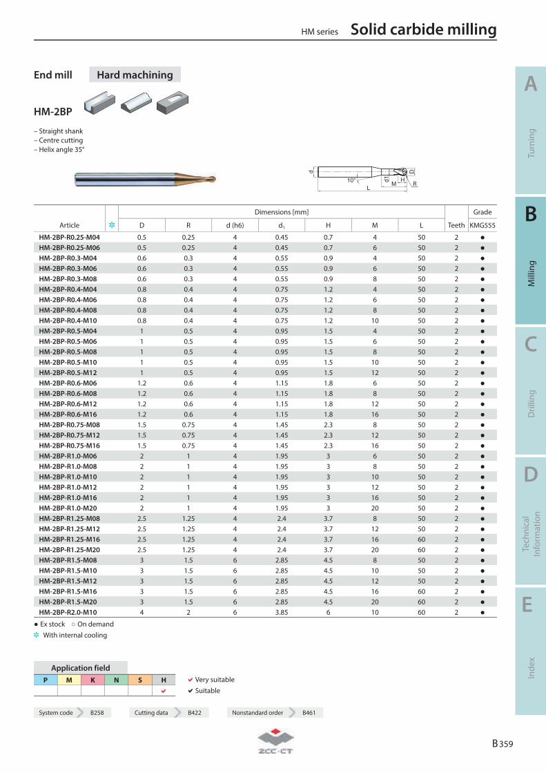
System code B258 Cutting data B422 Nonstandard order B461
End mill Hard machining
HM-2BP
– Straight shank – Centre cutting – Helix angle 35°
d
L10° H
Md1
D
R
Dimensions [mm] Grade
Article D R d (h6) d1 H M L Teeth KMG555
HM-2BP-R0.25-M04 0.5 0.25 4 0.45 0.7 4 50 2 ● HM-2BP-R0.25-M06 0.5 0.25 4 0.45 0.7 6 50 2 ● HM-2BP-R0.3-M04 0.6 0.3 4 0.55 0.9 4 50 2 ● HM-2BP-R0.3-M06 0.6 0.3 4 0.55 0.9 6 50 2 ● HM-2BP-R0.3-M08 0.6 0.3 4 0.55 0.9 8 50 2 ● HM-2BP-R0.4-M04 0.8 0.4 4 0.75 1.2 4 50 2 ● HM-2BP-R0.4-M06 0.8 0.4 4 0.75 1.2 6 50 2 ● HM-2BP-R0.4-M08 0.8 0.4 4 0.75 1.2 8 50 2 ● HM-2BP-R0.4-M10 0.8 0.4 4 0.75 1.2 10 50 2 ● HM-2BP-R0.5-M04 1 0.5 4 0.95 1.5 4 50 2 ● HM-2BP-R0.5-M06 1 0.5 4 0.95 1.5 6 50 2 ● HM-2BP-R0.5-M08 1 0.5 4 0.95 1.5 8 50 2 ● HM-2BP-R0.5-M10 1 0.5 4 0.95 1.5 10 50 2 ● HM-2BP-R0.5-M12 1 0.5 4 0.95 1.5 12 50 2 ● HM-2BP-R0.6-M06 1.2 0.6 4 1.15 1.8 6 50 2 ● HM-2BP-R0.6-M08 1.2 0.6 4 1.15 1.8 8 50 2 ● HM-2BP-R0.6-M12 1.2 0.6 4 1.15 1.8 12 50 2 ● HM-2BP-R0.6-M16 1.2 0.6 4 1.15 1.8 16 50 2 ● HM-2BP-R0.75-M08 1.5 0.75 4 1.45 2.3 8 50 2 ● HM-2BP-R0.75-M12 1.5 0.75 4 1.45 2.3 12 50 2 ● HM-2BP-R0.75-M16 1.5 0.75 4 1.45 2.3 16 50 2 ● HM-2BP-R1.0-M06 2 1 4 1.95 3 6 50 2 ● HM-2BP-R1.0-M08 2 1 4 1.95 3 8 50 2 ● HM-2BP-R1.0-M10 2 1 4 1.95 3 10 50 2 ● HM-2BP-R1.0-M12 2 1 4 1.95 3 12 50 2 ● HM-2BP-R1.0-M16 2 1 4 1.95 3 16 50 2 ● HM-2BP-R1.0-M20 2 1 4 1.95 3 20 50 2 ● HM-2BP-R1.25-M08 2.5 1.25 4 2.4 3.7 8 50 2 ● HM-2BP-R1.25-M12 2.5 1.25 4 2.4 3.7 12 50 2 ● HM-2BP-R1.25-M16 2.5 1.25 4 2.4 3.7 16 60 2 ● HM-2BP-R1.25-M20 2.5 1.25 4 2.4 3.7 20 60 2 ● HM-2BP-R1.5-M08 3 1.5 6 2.85 4.5 8 50 2 ● HM-2BP-R1.5-M10 3 1.5 6 2.85 4.5 10 50 2 ● HM-2BP-R1.5-M12 3 1.5 6 2.85 4.5 12 50 2 ● HM-2BP-R1.5-M16 3 1.5 6 2.85 4.5 16 60 2 ● HM-2BP-R1.5-M20 3 1.5 6 2.85 4.5 20 60 2 ● HM-2BP-R2.0-M10 4 2 6 3.85 6 10 60 2 ●
● Ex stock ○ On demand With internal cooling
Application field P M K N S H
Very suitable Suitable
HM series Solid carbide milling
A
Turn
ing
B
Mill
ing
C
Dril
ling
D
Tech
nica
l In
form
atio
n
E
Inde
x
B 359
System code B258 Cutting data B422 Nonstandard order B461
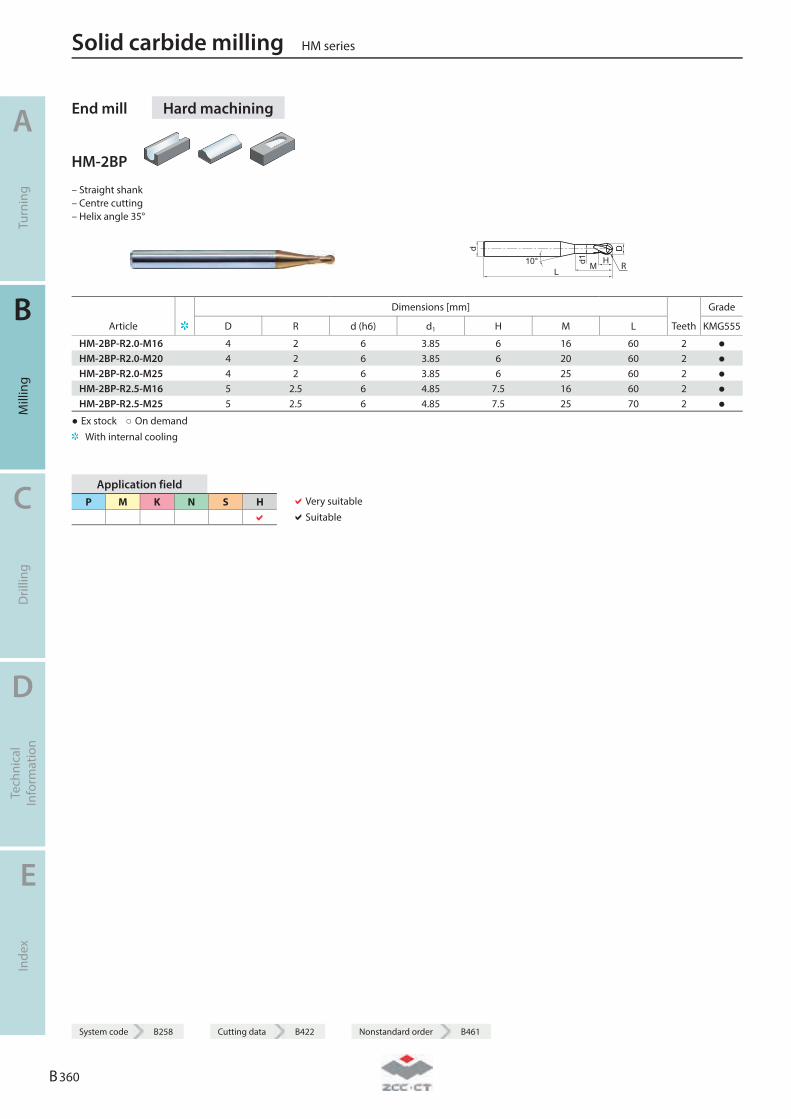
End mill Hard machining
HM-2BP
– Straight shank – Centre cutting – Helix angle 35°
d
L10° H
Md1
D
R
Dimensions [mm] Grade
Article D R d (h6) d1 H M L Teeth KMG555
HM-2BP-R2.0-M16 4 2 6 3.85 6 16 60 2 ● HM-2BP-R2.0-M20 4 2 6 3.85 6 20 60 2 ● HM-2BP-R2.0-M25 4 2 6 3.85 6 25 60 2 ● HM-2BP-R2.5-M16 5 2.5 6 4.85 7.5 16 60 2 ● HM-2BP-R2.5-M25 5 2.5 6 4.85 7.5 25 70 2 ●
● Ex stock ○ On demand With internal cooling
Application field P M K N S H
Very suitable Suitable
Solid carbide milling HM series
A
Turn
ing
B
Mill
ing
C
Dril
ling
D
Tech
nica
l In
form
atio
n
E
Inde
x
B 360
System code B258 Cutting data B422 Nonstandard order B461
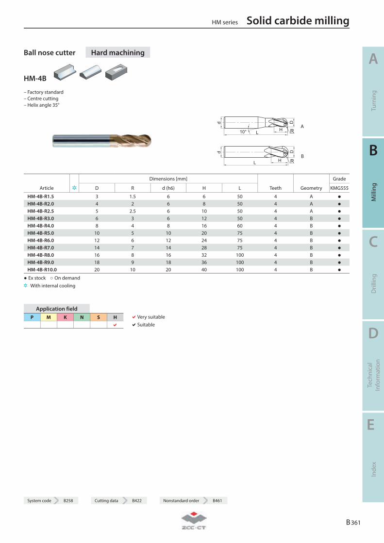
System code B258 Cutting data B422 Nonstandard order B461
Ball nose cutter Hard machining
HM-4B
– Factory standard – Centre cutting – Helix angle 35°
d
L H
D
10° R A
d
L H
D
R B
Dimensions [mm] Grade
Article D R d (h6) H L Teeth Geometry KMG555
HM-4B-R1.5 3 1.5 6 6 50 4 A ● HM-4B-R2.0 4 2 6 8 50 4 A ● HM-4B-R2.5 5 2.5 6 10 50 4 A ● HM-4B-R3.0 6 3 6 12 50 4 B ● HM-4B-R4.0 8 4 8 16 60 4 B ● HM-4B-R5.0 10 5 10 20 75 4 B ● HM-4B-R6.0 12 6 12 24 75 4 B ● HM-4B-R7.0 14 7 14 28 75 4 B ● HM-4B-R8.0 16 8 16 32 100 4 B ● HM-4B-R9.0 18 9 18 36 100 4 B ● HM-4B-R10.0 20 10 20 40 100 4 B ●
● Ex stock ○ On demand With internal cooling
Application field P M K N S H
Very suitable Suitable
HM series Solid carbide milling
A
Turn
ing
B
Mill
ing
C
Dril
ling
D
Tech
nica
l In
form
atio
n
E
Inde
x
B 361
System code B258 Cutting data B422 Nonstandard order B461
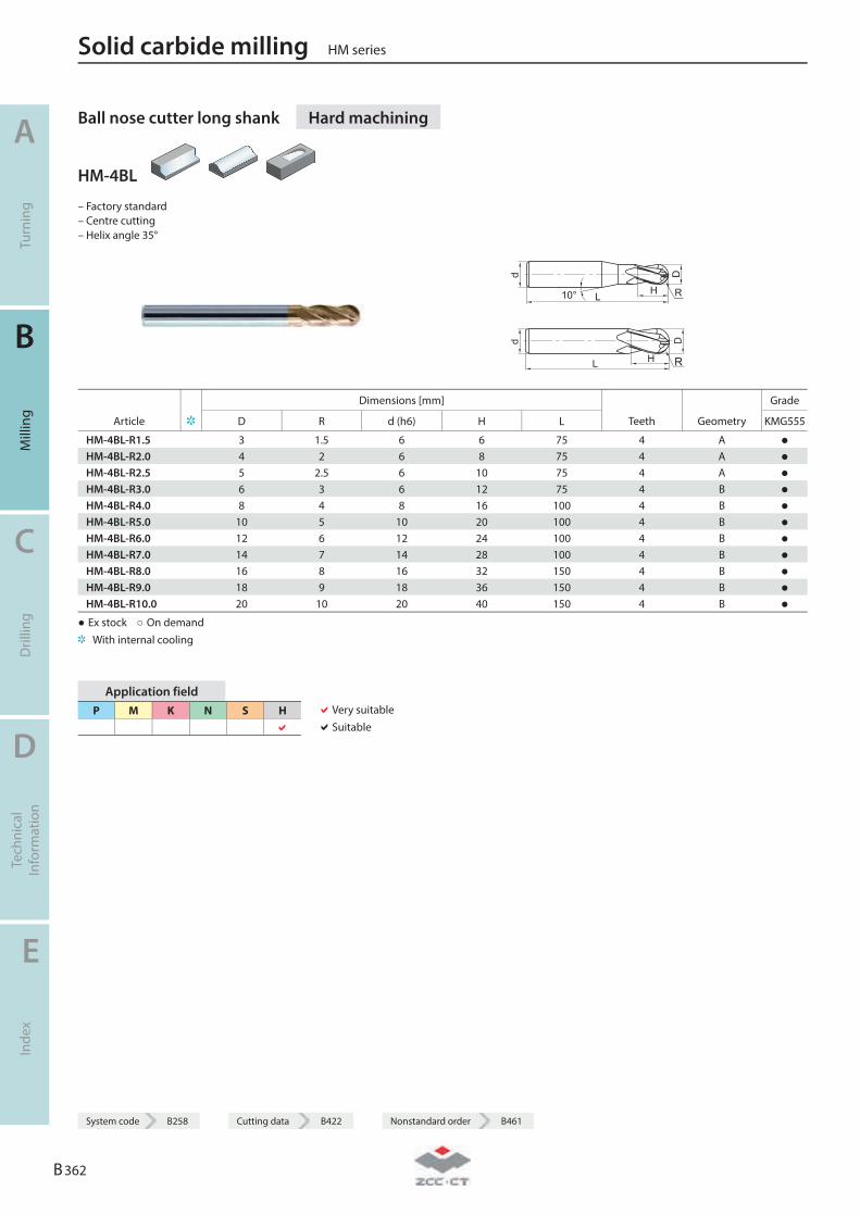
Ball nose cutter long shank Hard machining
HM-4BL
– Factory standard – Centre cutting – Helix angle 35°
d
L H
D
10° R
d
L H
D
R
Dimensions [mm] Grade
Article D R d (h6) H L Teeth Geometry KMG555
HM-4BL-R1.5 3 1.5 6 6 75 4 A ● HM-4BL-R2.0 4 2 6 8 75 4 A ● HM-4BL-R2.5 5 2.5 6 10 75 4 A ● HM-4BL-R3.0 6 3 6 12 75 4 B ● HM-4BL-R4.0 8 4 8 16 100 4 B ● HM-4BL-R5.0 10 5 10 20 100 4 B ● HM-4BL-R6.0 12 6 12 24 100 4 B ● HM-4BL-R7.0 14 7 14 28 100 4 B ● HM-4BL-R8.0 16 8 16 32 150 4 B ● HM-4BL-R9.0 18 9 18 36 150 4 B ● HM-4BL-R10.0 20 10 20 40 150 4 B ●
● Ex stock ○ On demand With internal cooling
Application field P M K N S H
Very suitable Suitable
Solid carbide milling HM series
A
Turn
ing
B
Mill
ing
C
Dril
ling
D
Tech
nica
l In
form
atio
n
E
Inde
x
B 362
System code B258 Cutting data B422 Nonstandard order B461
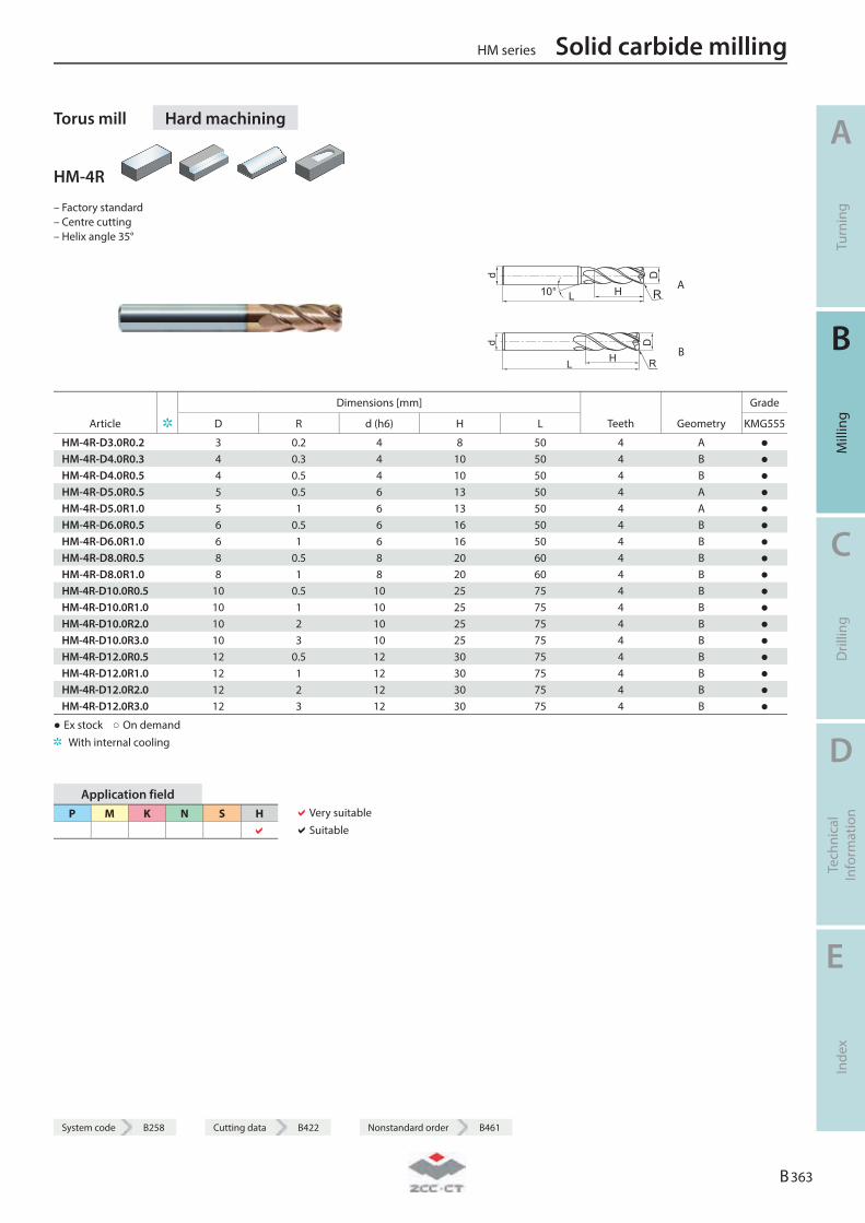
System code B258 Cutting data B422 Nonstandard order B461
Torus mill Hard machining
HM-4R
– Factory standard – Centre cutting – Helix angle 35°
R A
R B
Dimensions [mm] Grade
Article D R d (h6) H L Teeth Geometry KMG555
HM-4R-D3.0R0.2 3 0.2 4 8 50 4 A ● HM-4R-D4.0R0.3 4 0.3 4 10 50 4 B ● HM-4R-D4.0R0.5 4 0.5 4 10 50 4 B ● HM-4R-D5.0R0.5 5 0.5 6 13 50 4 A ● HM-4R-D5.0R1.0 5 1 6 13 50 4 A ● HM-4R-D6.0R0.5 6 0.5 6 16 50 4 B ● HM-4R-D6.0R1.0 6 1 6 16 50 4 B ● HM-4R-D8.0R0.5 8 0.5 8 20 60 4 B ● HM-4R-D8.0R1.0 8 1 8 20 60 4 B ● HM-4R-D10.0R0.5 10 0.5 10 25 75 4 B ● HM-4R-D10.0R1.0 10 1 10 25 75 4 B ● HM-4R-D10.0R2.0 10 2 10 25 75 4 B ● HM-4R-D10.0R3.0 10 3 10 25 75 4 B ● HM-4R-D12.0R0.5 12 0.5 12 30 75 4 B ● HM-4R-D12.0R1.0 12 1 12 30 75 4 B ● HM-4R-D12.0R2.0 12 2 12 30 75 4 B ● HM-4R-D12.0R3.0 12 3 12 30 75 4 B ●
● Ex stock ○ On demand With internal cooling
Application field P M K N S H
Very suitable Suitable
HM series Solid carbide milling
A
Turn
ing
B
Mill
ing
C
Dril
ling
D
Tech
nica
l In
form
atio
n
E
Inde
x
B 363
System code B258 Cutting data B422 Nonstandard order B461
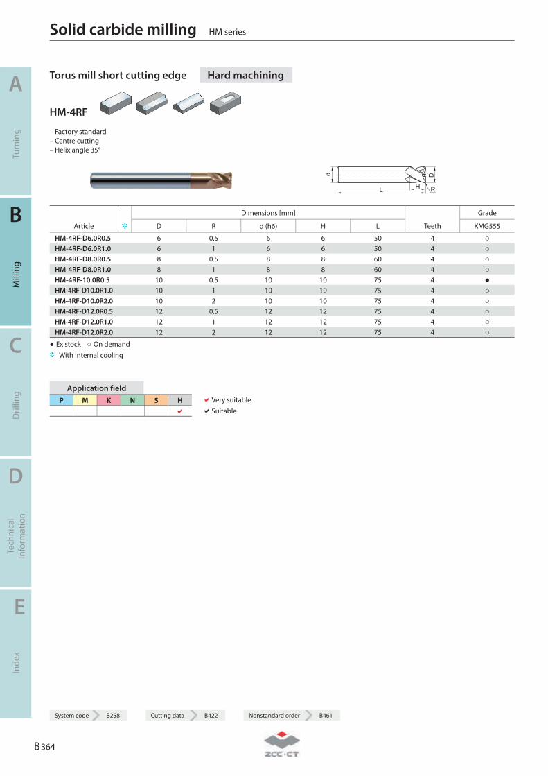
Torus mill short cutting edge Hard machining
HM-4RF
– Factory standard – Centre cutting – Helix angle 35°
L
D
H
d
R
Dimensions [mm] Grade
Article D R d (h6) H L Teeth KMG555
HM-4RF-D6.0R0.5 6 0.5 6 6 50 4 ○ HM-4RF-D6.0R1.0 6 1 6 6 50 4 ○ HM-4RF-D8.0R0.5 8 0.5 8 8 60 4 ○ HM-4RF-D8.0R1.0 8 1 8 8 60 4 ○ HM-4RF-10.0R0.5 10 0.5 10 10 75 4 ● HM-4RF-D10.0R1.0 10 1 10 10 75 4 ○ HM-4RF-D10.0R2.0 10 2 10 10 75 4 ○ HM-4RF-D12.0R0.5 12 0.5 12 12 75 4 ○ HM-4RF-D12.0R1.0 12 1 12 12 75 4 ○ HM-4RF-D12.0R2.0 12 2 12 12 75 4 ○
● Ex stock ○ On demand With internal cooling
Application field P M K N S H
Very suitable Suitable
Solid carbide milling HM series
A
Turn
ing
B
Mill
ing
C
Dril
ling
D
Tech
nica
l In
form
atio
n
E
Inde
x
B 364
System code B258 Cutting data B422 Nonstandard order B461
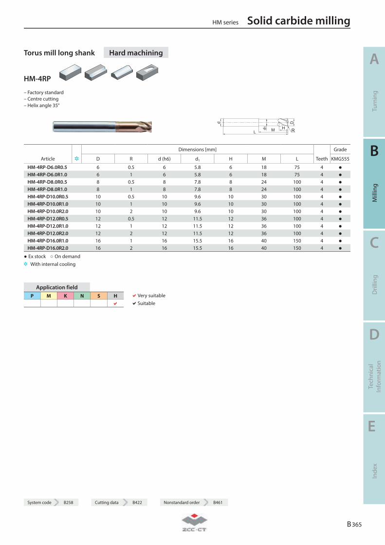
System code B258 Cutting data B422 Nonstandard order B461
Torus mill long shank Hard machining
HM-4RP
– Factory standard – Centre cutting – Helix angle 35°
R
Dimensions [mm] Grade
Article D R d (h6) d1 H M L Teeth KMG555
HM-4RP-D6.0R0.5 6 0.5 6 5.8 6 18 75 4 ● HM-4RP-D6.0R1.0 6 1 6 5.8 6 18 75 4 ● HM-4RP-D8.0R0.5 8 0.5 8 7.8 8 24 100 4 ● HM-4RP-D8.0R1.0 8 1 8 7.8 8 24 100 4 ● HM-4RP-D10.0R0.5 10 0.5 10 9.6 10 30 100 4 ● HM-4RP-D10.0R1.0 10 1 10 9.6 10 30 100 4 ● HM-4RP-D10.0R2.0 10 2 10 9.6 10 30 100 4 ● HM-4RP-D12.0R0.5 12 0.5 12 11.5 12 36 100 4 ● HM-4RP-D12.0R1.0 12 1 12 11.5 12 36 100 4 ● HM-4RP-D12.0R2.0 12 2 12 11.5 12 36 100 4 ● HM-4RP-D16.0R1.0 16 1 16 15.5 16 40 150 4 ● HM-4RP-D16.0R2.0 16 2 16 15.5 16 40 150 4 ●
● Ex stock ○ On demand With internal cooling
Application field P M K N S H
Very suitable Suitable
HM series Solid carbide milling
A
Turn
ing
B
Mill
ing
C
Dril
ling
D
Tech
nica
l In
form
atio
n
E
Inde
x
B 365
System code B258 Cutting data B422 Nonstandard order B461

Solid carbide milling HM series
A
Turn
ing
B
Mill
ing
C
Dril
ling
D
Tech
nica
l In
form
atio
n
E
Inde
x
B 366
Notes
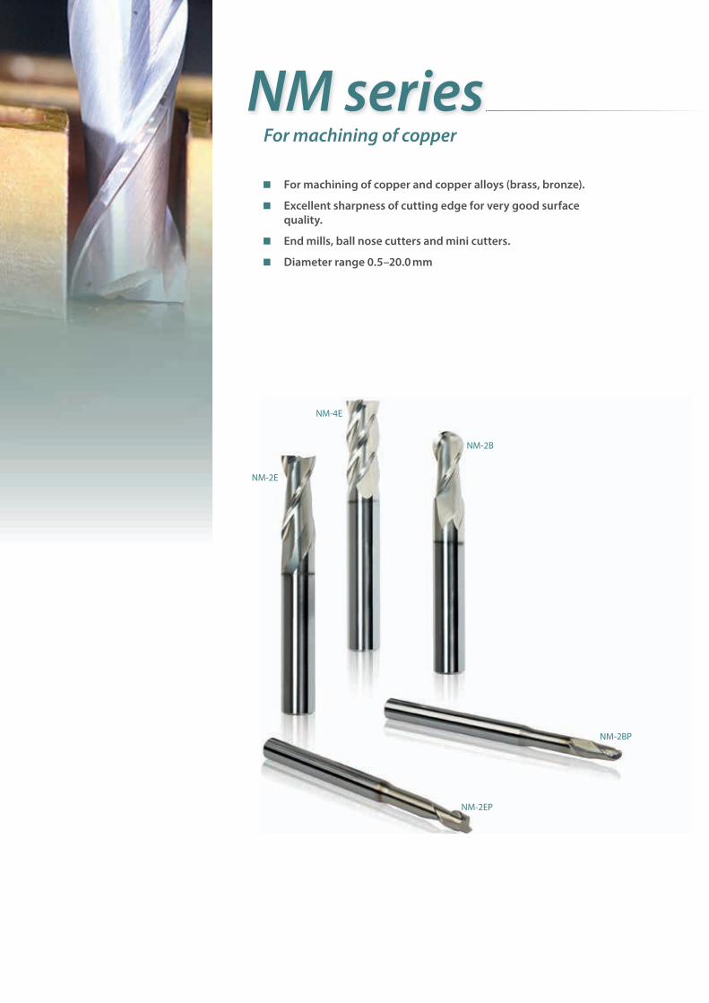
For machining of copper
For machining of copper and copper alloys (brass, bronze).
Excellent sharpness of cutting edge for very good surface quality.
End mills, ball nose cutters and mini cutters.
Diameter range 0.5–20.0 mm
NM series
NM-4E
NM-2B
NM-2BP
NM-2EP
NM-2E
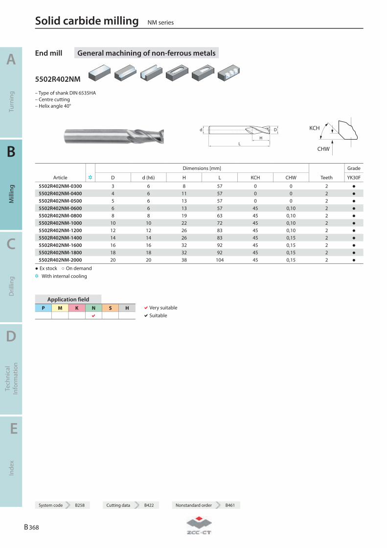
End mill General machining of non-ferrous metals
5502R402NM
– Type of shank DIN 6535HA – Centre cutting – Helix angle 40°
LH
Dd
KCH
CHW
Dimensions [mm] Grade
Article D d (h6) H L KCH CHW Teeth YK30F
5502R402NM-0300 3 6 8 57 0 0 2 ● 5502R402NM-0400 4 6 11 57 0 0 2 ● 5502R402NM-0500 5 6 13 57 0 0 2 ● 5502R402NM-0600 6 6 13 57 45 0,10 2 ● 5502R402NM-0800 8 8 19 63 45 0,10 2 ● 5502R402NM-1000 10 10 22 72 45 0,10 2 ● 5502R402NM-1200 12 12 26 83 45 0,10 2 ● 5502R402NM-1400 14 14 26 83 45 0,15 2 ● 5502R402NM-1600 16 16 32 92 45 0,15 2 ● 5502R402NM-1800 18 18 32 92 45 0,15 2 ● 5502R402NM-2000 20 20 38 104 45 0,15 2 ●
● Ex stock ○ On demand With internal cooling
Application field P M K N S H
Very suitable Suitable
Solid carbide milling NM series
A
Turn
ing
B
Mill
ing
C
Dril
ling
D
Tech
nica
l In
form
atio
n
E
Inde
x
B 368
System code B258 Cutting data B422 Nonstandard order B461
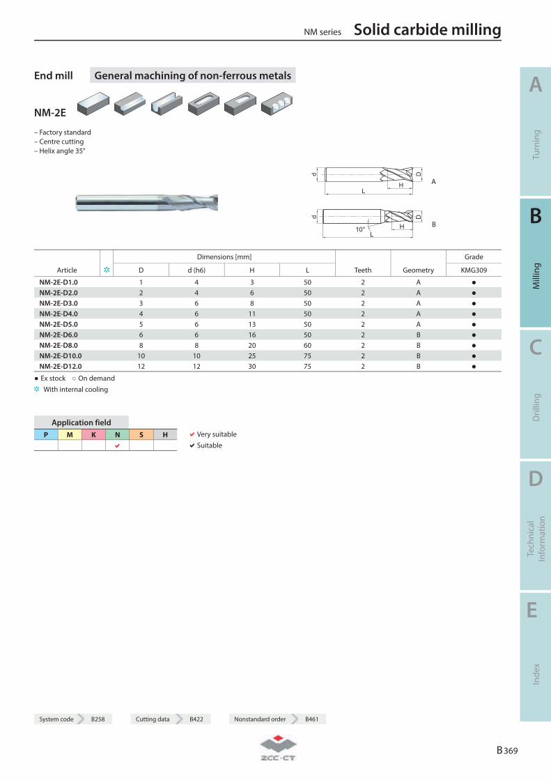
System code B258 Cutting data B422 Nonstandard order B461
End mill General machining of non-ferrous metals
NM-2E
– Factory standard – Centre cutting – Helix angle 35°
L
D
H
d
A
L
d
H
D
10° B
Dimensions [mm] Grade
Article D d (h6) H L Teeth Geometry KMG309
NM-2E-D1.0 1 4 3 50 2 A ● NM-2E-D2.0 2 4 6 50 2 A ● NM-2E-D3.0 3 6 8 50 2 A ● NM-2E-D4.0 4 6 11 50 2 A ● NM-2E-D5.0 5 6 13 50 2 A ● NM-2E-D6.0 6 6 16 50 2 B ● NM-2E-D8.0 8 8 20 60 2 B ● NM-2E-D10.0 10 10 25 75 2 B ● NM-2E-D12.0 12 12 30 75 2 B ●
● Ex stock ○ On demand With internal cooling
Application field P M K N S H
Very suitable Suitable
NM series Solid carbide milling
A
Turn
ing
B
Mill
ing
C
Dril
ling
D
Tech
nica
l In
form
atio
n
E
Inde
x
B 369
System code B258 Cutting data B422 Nonstandard order B461
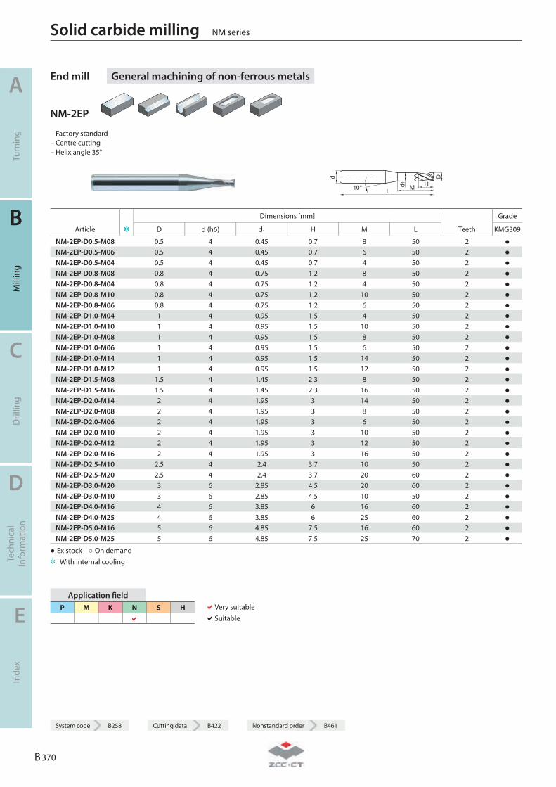
End mill General machining of non-ferrous metals
NM-2EP
– Factory standard – Centre cutting – Helix angle 35°
L
D
H
d
d1 M10°
Dimensions [mm] Grade
Article D d (h6) d1 H M L Teeth KMG309
NM-2EP-D0.5-M08 0.5 4 0.45 0.7 8 50 2 ● NM-2EP-D0.5-M06 0.5 4 0.45 0.7 6 50 2 ● NM-2EP-D0.5-M04 0.5 4 0.45 0.7 4 50 2 ● NM-2EP-D0.8-M08 0.8 4 0.75 1.2 8 50 2 ● NM-2EP-D0.8-M04 0.8 4 0.75 1.2 4 50 2 ● NM-2EP-D0.8-M10 0.8 4 0.75 1.2 10 50 2 ● NM-2EP-D0.8-M06 0.8 4 0.75 1.2 6 50 2 ● NM-2EP-D1.0-M04 1 4 0.95 1.5 4 50 2 ● NM-2EP-D1.0-M10 1 4 0.95 1.5 10 50 2 ● NM-2EP-D1.0-M08 1 4 0.95 1.5 8 50 2 ● NM-2EP-D1.0-M06 1 4 0.95 1.5 6 50 2 ● NM-2EP-D1.0-M14 1 4 0.95 1.5 14 50 2 ● NM-2EP-D1.0-M12 1 4 0.95 1.5 12 50 2 ● NM-2EP-D1.5-M08 1.5 4 1.45 2.3 8 50 2 ● NM-2EP-D1.5-M16 1.5 4 1.45 2.3 16 50 2 ● NM-2EP-D2.0-M14 2 4 1.95 3 14 50 2 ● NM-2EP-D2.0-M08 2 4 1.95 3 8 50 2 ● NM-2EP-D2.0-M06 2 4 1.95 3 6 50 2 ● NM-2EP-D2.0-M10 2 4 1.95 3 10 50 2 ● NM-2EP-D2.0-M12 2 4 1.95 3 12 50 2 ● NM-2EP-D2.0-M16 2 4 1.95 3 16 50 2 ● NM-2EP-D2.5-M10 2.5 4 2.4 3.7 10 50 2 ● NM-2EP-D2.5-M20 2.5 4 2.4 3.7 20 60 2 ● NM-2EP-D3.0-M20 3 6 2.85 4.5 20 60 2 ● NM-2EP-D3.0-M10 3 6 2.85 4.5 10 50 2 ● NM-2EP-D4.0-M16 4 6 3.85 6 16 60 2 ● NM-2EP-D4.0-M25 4 6 3.85 6 25 60 2 ● NM-2EP-D5.0-M16 5 6 4.85 7.5 16 60 2 ● NM-2EP-D5.0-M25 5 6 4.85 7.5 25 70 2 ●
● Ex stock ○ On demand With internal cooling
Application field P M K N S H
Very suitable Suitable
Solid carbide milling NM series
A
Turn
ing
B
Mill
ing
C
Dril
ling
D
Tech
nica
l In
form
atio
n
E
Inde
x
B 370
System code B258 Cutting data B422 Nonstandard order B461
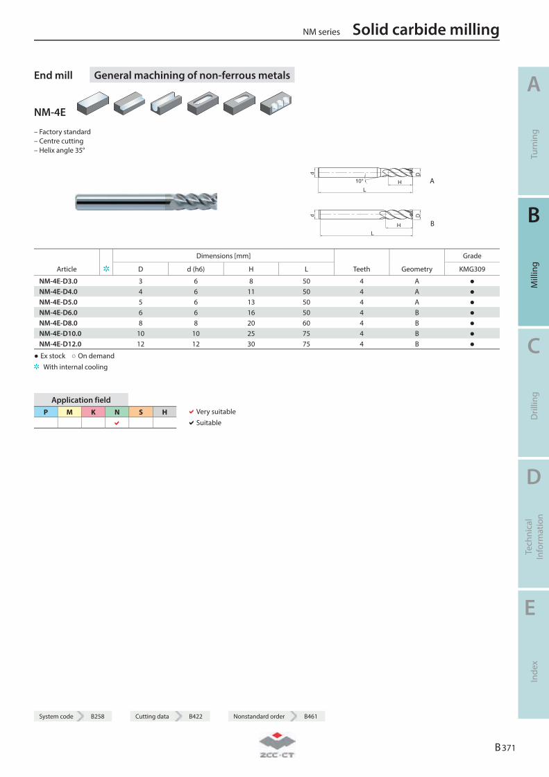
System code B258 Cutting data B422 Nonstandard order B461
End mill General machining of non-ferrous metals
NM-4E
– Factory standard – Centre cutting – Helix angle 35°
L
D
H10°
d
A
LH
Dd
B
Dimensions [mm] Grade
Article D d (h6) H L Teeth Geometry KMG309
NM-4E-D3.0 3 6 8 50 4 A ● NM-4E-D4.0 4 6 11 50 4 A ● NM-4E-D5.0 5 6 13 50 4 A ● NM-4E-D6.0 6 6 16 50 4 B ● NM-4E-D8.0 8 8 20 60 4 B ● NM-4E-D10.0 10 10 25 75 4 B ● NM-4E-D12.0 12 12 30 75 4 B ●
● Ex stock ○ On demand With internal cooling
Application field P M K N S H
Very suitable Suitable
NM series Solid carbide milling
A
Turn
ing
B
Mill
ing
C
Dril
ling
D
Tech
nica
l In
form
atio
n
E
Inde
x
B 371
System code B258 Cutting data B422 Nonstandard order B461

Ball nose cutter General machining of non-ferrous metals
NM-2B
– Factory standard – Centre cutting – Helix angle 35°
R A
R B
Dimensions [mm] Grade
Article D R d (h6) H L Teeth Geometry KMG309
NM-2B-R0.5 1 0.5 4 2 50 2 A ● NM-2B-R0.75 1.5 0.75 4 3 50 2 A ● NM-2B-R1.0 2 1 4 4 50 2 A ● NM-2B-R1.25 2.5 1.25 4 5 50 2 A ● NM-2B-R1.5 3 1.5 6 6 50 2 A ● NM-2B-R1.75 3.5 1.75 6 8 50 2 A ● NM-2B-R2.0 4 2 6 8 50 2 A ● NM-2B-R2.5 5 2.5 6 10 50 2 A ● NM-2B-R3.0 6 3 6 12 50 2 B ● NM-2B-R4.0 8 4 8 16 60 2 B ● NM-2B-R5.0 10 5 10 20 75 2 B ● NM-2B-R6.0 12 6 12 24 75 2 B ●
● Ex stock ○ On demand With internal cooling
Application field P M K N S H
Very suitable Suitable
Solid carbide milling NM series
A
Turn
ing
B
Mill
ing
C
Dril
ling
D
Tech
nica
l In
form
atio
n
E
Inde
x
B 372
System code B258 Cutting data B422 Nonstandard order B461
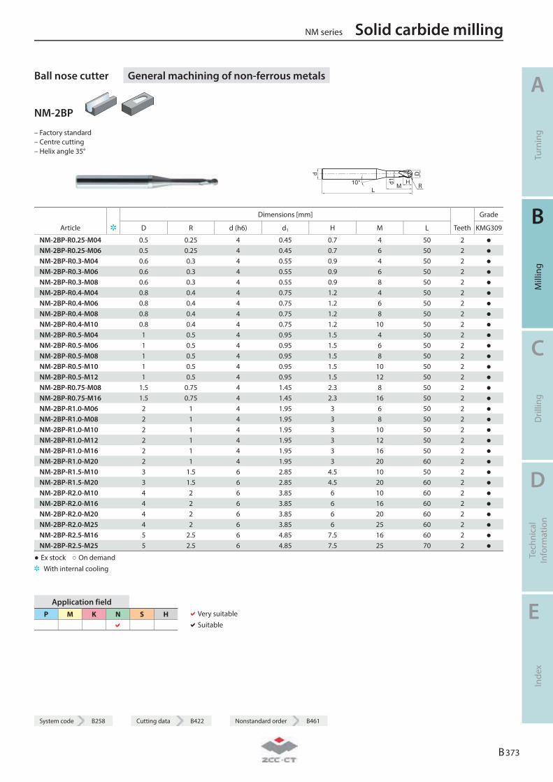
System code B258 Cutting data B422 Nonstandard order B461
Ball nose cutter General machining of non-ferrous metals
NM-2BP
– Factory standard – Centre cutting – Helix angle 35°
d
L10° H
Md1
D
R
Dimensions [mm] Grade
Article D R d (h6) d1 H M L Teeth KMG309
NM-2BP-R0.25-M04 0.5 0.25 4 0.45 0.7 4 50 2 ● NM-2BP-R0.25-M06 0.5 0.25 4 0.45 0.7 6 50 2 ● NM-2BP-R0.3-M04 0.6 0.3 4 0.55 0.9 4 50 2 ● NM-2BP-R0.3-M06 0.6 0.3 4 0.55 0.9 6 50 2 ● NM-2BP-R0.3-M08 0.6 0.3 4 0.55 0.9 8 50 2 ● NM-2BP-R0.4-M04 0.8 0.4 4 0.75 1.2 4 50 2 ● NM-2BP-R0.4-M06 0.8 0.4 4 0.75 1.2 6 50 2 ● NM-2BP-R0.4-M08 0.8 0.4 4 0.75 1.2 8 50 2 ● NM-2BP-R0.4-M10 0.8 0.4 4 0.75 1.2 10 50 2 ● NM-2BP-R0.5-M04 1 0.5 4 0.95 1.5 4 50 2 ● NM-2BP-R0.5-M06 1 0.5 4 0.95 1.5 6 50 2 ● NM-2BP-R0.5-M08 1 0.5 4 0.95 1.5 8 50 2 ● NM-2BP-R0.5-M10 1 0.5 4 0.95 1.5 10 50 2 ● NM-2BP-R0.5-M12 1 0.5 4 0.95 1.5 12 50 2 ● NM-2BP-R0.75-M08 1.5 0.75 4 1.45 2.3 8 50 2 ● NM-2BP-R0.75-M16 1.5 0.75 4 1.45 2.3 16 50 2 ● NM-2BP-R1.0-M06 2 1 4 1.95 3 6 50 2 ● NM-2BP-R1.0-M08 2 1 4 1.95 3 8 50 2 ● NM-2BP-R1.0-M10 2 1 4 1.95 3 10 50 2 ● NM-2BP-R1.0-M12 2 1 4 1.95 3 12 50 2 ● NM-2BP-R1.0-M16 2 1 4 1.95 3 16 50 2 ● NM-2BP-R1.0-M20 2 1 4 1.95 3 20 60 2 ● NM-2BP-R1.5-M10 3 1.5 6 2.85 4.5 10 50 2 ● NM-2BP-R1.5-M20 3 1.5 6 2.85 4.5 20 60 2 ● NM-2BP-R2.0-M10 4 2 6 3.85 6 10 60 2 ● NM-2BP-R2.0-M16 4 2 6 3.85 6 16 60 2 ● NM-2BP-R2.0-M20 4 2 6 3.85 6 20 60 2 ● NM-2BP-R2.0-M25 4 2 6 3.85 6 25 60 2 ● NM-2BP-R2.5-M16 5 2.5 6 4.85 7.5 16 60 2 ● NM-2BP-R2.5-M25 5 2.5 6 4.85 7.5 25 70 2 ●
● Ex stock ○ On demand With internal cooling
Application field P M K N S H
Very suitable Suitable
NM series Solid carbide milling
A
Turn
ing
B
Mill
ing
C
Dril
ling
D
Tech
nica
l In
form
atio
n
E
Inde
x
B 373
System code B258 Cutting data B422 Nonstandard order B461
Solid carbide milling NM series
A
Turn
ing
B
Mill
ing
C
Dril
ling
D
Tech
nica
l In
form
atio
n
E
Inde
x
B 374
Notes
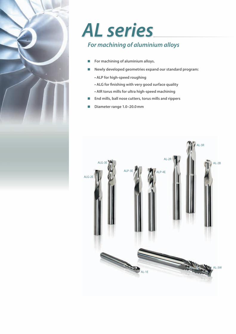
For machining of aluminium alloys.
Newly developed geometries expand our standard program:
• ALP for high-speed roughing
• ALG for � nishing with very good surface quality
• AIR torus mills for ultra high-speed machining
End mills, ball nose cutters, torus mills and rippers
Diameter range 1.0–20.0 mm
For machining of aluminium alloys
AL series
ALG-3E
ALP-4E
AL-2B
AL-3WAL-1E
ALG-2E
ALP-3E
AL-2R
AL-3R
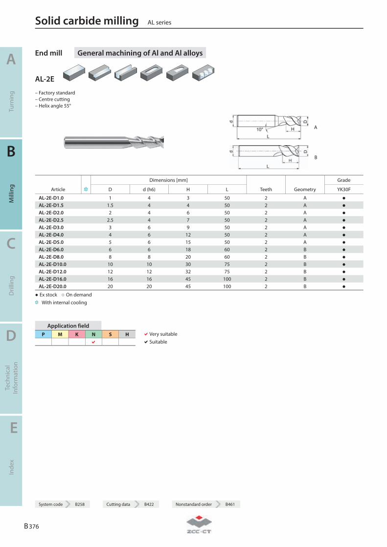
End mill General machining of Al and Al alloys
AL-2E
– Factory standard – Centre cutting – Helix angle 55°
A
B
Dimensions [mm] Grade
Article D d (h6) H L Teeth Geometry YK30F
AL-2E-D1.0 1 4 3 50 2 A ● AL-2E-D1.5 1.5 4 4 50 2 A ● AL-2E-D2.0 2 4 6 50 2 A ● AL-2E-D2.5 2.5 4 7 50 2 A ● AL-2E-D3.0 3 6 9 50 2 A ● AL-2E-D4.0 4 6 12 50 2 A ● AL-2E-D5.0 5 6 15 50 2 A ● AL-2E-D6.0 6 6 18 60 2 B ● AL-2E-D8.0 8 8 20 60 2 B ● AL-2E-D10.0 10 10 30 75 2 B ● AL-2E-D12.0 12 12 32 75 2 B ● AL-2E-D16.0 16 16 45 100 2 B ● AL-2E-D20.0 20 20 45 100 2 B ●
● Ex stock ○ On demand With internal cooling
Application field P M K N S H
Very suitable Suitable
Solid carbide milling AL series
A
Turn
ing
B
Mill
ing
C
Dril
ling
D
Tech
nica
l In
form
atio
n
E
Inde
x
B 376
System code B258 Cutting data B422 Nonstandard order B461
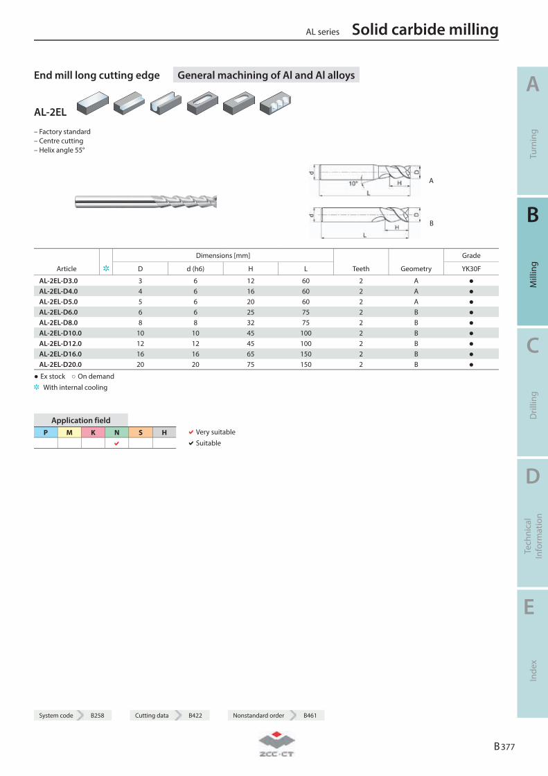
System code B258 Cutting data B422 Nonstandard order B461
End mill long cutting edge General machining of Al and Al alloys
AL-2EL
– Factory standard – Centre cutting – Helix angle 55°
A
B
Dimensions [mm] Grade
Article D d (h6) H L Teeth Geometry YK30F
AL-2EL-D3.0 3 6 12 60 2 A ● AL-2EL-D4.0 4 6 16 60 2 A ● AL-2EL-D5.0 5 6 20 60 2 A ● AL-2EL-D6.0 6 6 25 75 2 B ● AL-2EL-D8.0 8 8 32 75 2 B ● AL-2EL-D10.0 10 10 45 100 2 B ● AL-2EL-D12.0 12 12 45 100 2 B ● AL-2EL-D16.0 16 16 65 150 2 B ● AL-2EL-D20.0 20 20 75 150 2 B ●
● Ex stock ○ On demand With internal cooling
Application field P M K N S H
Very suitable Suitable
AL series Solid carbide milling
A
Turn
ing
B
Mill
ing
C
Dril
ling
D
Tech
nica
l In
form
atio
n
E
Inde
x
B 377
System code B258 Cutting data B422 Nonstandard order B461
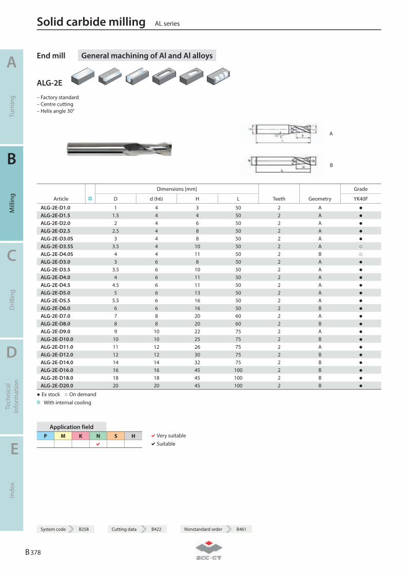
End mill General machining of Al and Al alloys
ALG-2E
– Factory standard – Centre cutting – Helix angle 30°
A
B
Dimensions [mm] Grade
Article D d (h6) H L Teeth Geometry YK40F
ALG-2E-D1.0 1 4 3 50 2 A ● ALG-2E-D1.5 1.5 4 4 50 2 A ● ALG-2E-D2.0 2 4 6 50 2 A ● ALG-2E-D2.5 2.5 4 8 50 2 A ● ALG-2E-D3.0S 3 4 8 50 2 A ● ALG-2E-D3.5S 3.5 4 10 50 2 A ○ ALG-2E-D4.0S 4 4 11 50 2 B ○ ALG-2E-D3.0 3 6 8 50 2 A ● ALG-2E-D3.5 3.5 6 10 50 2 A ● ALG-2E-D4.0 4 6 11 50 2 A ● ALG-2E-D4.5 4.5 6 11 50 2 A ● ALG-2E-D5.0 5 6 13 50 2 A ● ALG-2E-D5.5 5.5 6 16 50 2 A ● ALG-2E-D6.0 6 6 16 50 2 B ● ALG-2E-D7.0 7 8 20 60 2 A ● ALG-2E-D8.0 8 8 20 60 2 B ● ALG-2E-D9.0 9 10 22 75 2 A ● ALG-2E-D10.0 10 10 25 75 2 B ● ALG-2E-D11.0 11 12 26 75 2 A ● ALG-2E-D12.0 12 12 30 75 2 B ● ALG-2E-D14.0 14 14 32 75 2 B ● ALG-2E-D16.0 16 16 45 100 2 B ● ALG-2E-D18.0 18 18 45 100 2 B ● ALG-2E-D20.0 20 20 45 100 2 B ●
● Ex stock ○ On demand With internal cooling
Application field P M K N S H
Very suitable Suitable
Solid carbide milling AL series
A
Turn
ing
B
Mill
ing
C
Dril
ling
D
Tech
nica
l In
form
atio
n
E
Inde
x
B 378
System code B258 Cutting data B422 Nonstandard order B461
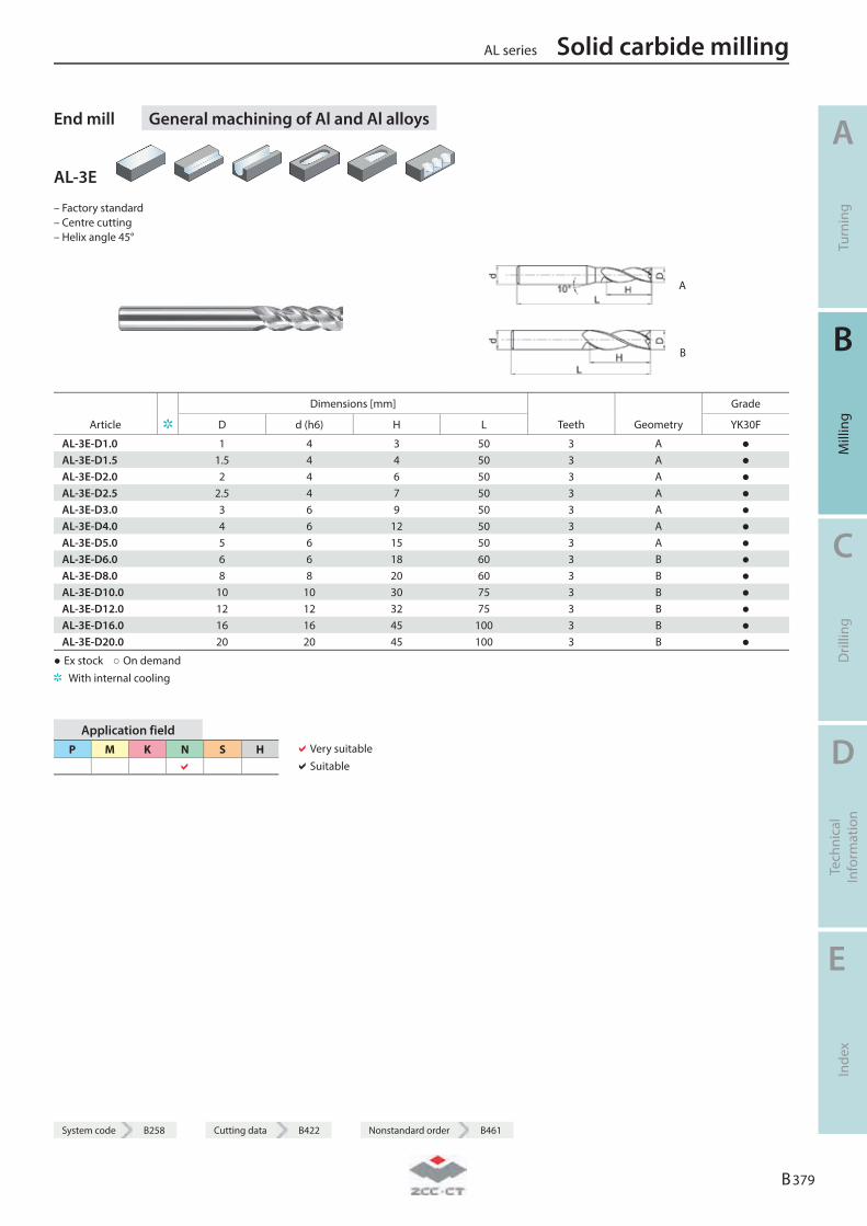
System code B258 Cutting data B422 Nonstandard order B461
End mill General machining of Al and Al alloys
AL-3E
– Factory standard – Centre cutting – Helix angle 45°
A
B
Dimensions [mm] Grade
Article D d (h6) H L Teeth Geometry YK30F
AL-3E-D1.0 1 4 3 50 3 A ● AL-3E-D1.5 1.5 4 4 50 3 A ● AL-3E-D2.0 2 4 6 50 3 A ● AL-3E-D2.5 2.5 4 7 50 3 A ● AL-3E-D3.0 3 6 9 50 3 A ● AL-3E-D4.0 4 6 12 50 3 A ● AL-3E-D5.0 5 6 15 50 3 A ● AL-3E-D6.0 6 6 18 60 3 B ● AL-3E-D8.0 8 8 20 60 3 B ● AL-3E-D10.0 10 10 30 75 3 B ● AL-3E-D12.0 12 12 32 75 3 B ● AL-3E-D16.0 16 16 45 100 3 B ● AL-3E-D20.0 20 20 45 100 3 B ●
● Ex stock ○ On demand With internal cooling
Application field P M K N S H
Very suitable Suitable
AL series Solid carbide milling
A
Turn
ing
B
Mill
ing
C
Dril
ling
D
Tech
nica
l In
form
atio
n
E
Inde
x
B 379
System code B258 Cutting data B422 Nonstandard order B461
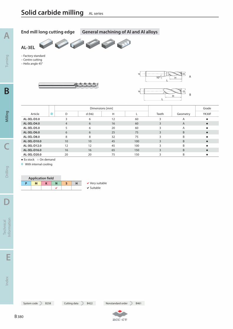
End mill long cutting edge General machining of Al and Al alloys
AL-3EL
– Factory standard – Centre cutting – Helix angle 45°
A
B
Dimensions [mm] Grade
Article D d (h6) H L Teeth Geometry YK30F
AL-3EL-D3.0 3 6 12 60 3 A ● AL-3EL-D4.0 4 6 16 60 3 A ● AL-3EL-D5.0 5 6 20 60 3 A ● AL-3EL-D6.0 6 6 25 75 3 B ● AL-3EL-D8.0 8 8 32 75 3 B ● AL-3EL-D10.0 10 10 45 100 3 B ● AL-3EL-D12.0 12 12 45 100 3 B ● AL-3EL-D16.0 16 16 65 150 3 B ● AL-3EL-D20.0 20 20 75 150 3 B ●
● Ex stock ○ On demand With internal cooling
Application field P M K N S H
Very suitable Suitable
Solid carbide milling AL series
A
Turn
ing
B
Mill
ing
C
Dril
ling
D
Tech
nica
l In
form
atio
n
E
Inde
x
B 380
System code B258 Cutting data B422 Nonstandard order B461
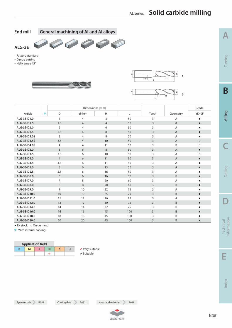
System code B258 Cutting data B422 Nonstandard order B461
End mill General machining of Al and Al alloys
ALG-3E
– Factory standard – Centre cutting – Helix angle 45°
10° A
B
Dimensions [mm] Grade
Article D d (h6) H L Teeth Geometry YK40F
ALG-3E-D1.0 1 4 3 50 3 A ● ALG-3E-D1.5 1.5 4 4 50 3 A ● ALG-3E-D2.0 2 4 6 50 3 A ● ALG-3E-D2.5 2.5 4 8 50 3 A ● ALG-3E-D3.0S 3 4 8 50 3 A ● ALG-3E-D3.5S 3.5 4 10 50 3 A ○ ALG-3E-D4.0S 4 4 11 50 3 B ○ ALG-3E-D3.0 3 6 8 50 3 A ● ALG-3E-D3.5 3.5 6 10 50 3 A ○ ALG-3E-D4.0 4 6 11 50 3 A ● ALG-3E-D4.5 4.5 6 11 50 3 A ● ALG-3E-D5.0 5 6 13 50 3 A ● ALG-3E-D5.5 5.5 6 16 50 3 A ● ALG-3E-D6.0 6 6 16 50 3 B ● ALG-3E-D7.0 7 8 20 60 3 A ● ALG-3E-D8.0 8 8 20 60 3 B ● ALG-3E-D9.0 9 10 22 75 3 A ● ALG-3E-D10.0 10 10 25 75 3 B ● ALG-3E-D11.0 11 12 26 75 3 A ● ALG-3E-D12.0 12 12 30 75 3 B ● ALG-3E-D14.0 14 14 32 75 3 B ● ALG-3E-D16.0 16 16 45 100 3 B ● ALG-3E-D18.0 18 18 45 100 3 B ● ALG-3E-D20.0 20 20 45 100 3 B ●
● Ex stock ○ On demand With internal cooling
Application field P M K N S H
Very suitable Suitable
AL series Solid carbide milling
A
Turn
ing
B
Mill
ing
C
Dril
ling
D
Tech
nica
l In
form
atio
n
E
Inde
x
B 381
System code B258 Cutting data B422 Nonstandard order B461

End mill High-performance machining of Al and Al alloys
ALP-3E
– Factory standard – Centre cutting – Helix angle 35°
10° A
B
Dimensions [mm] Grade
Article D d (h6) H L Teeth Geometry YK40F
ALP-3E-D1.0 1 4 3 50 3 A ● ALP-3E-D1.5 1.5 4 4 50 3 A ● ALP-3E-D2.0 2 4 6 50 3 A ● ALP-3E-D2.5 2.5 4 8 50 3 A ● ALP-3E-D3.0S 3 4 9 50 3 A ● ALP-3E-D4.0S 4 4 12 50 3 B ● ALP-3E-D3.0 3 6 8 50 3 A ● ALP-3E-D4.0 4 6 11 50 3 A ● ALP-3E-D4.5 4.5 6 11 50 3 A ● ALP-3E-D5.0 5 6 13 50 3 A ● ALP-3E-D5.5 5.5 6 16 50 3 A ● ALP-3E-D6.0 6 6 16 50 3 B ● ALP-3E-D7.0 7 8 20 60 3 B ○ ALP-3E-D8.0 8 8 20 60 3 B ● ALP-3E-D9.0 9 10 22 75 3 B ● ALP-3E-D10.0 10 10 25 75 3 B ● ALP-3E-D11.0 11 12 26 75 3 B ● ALP-3E-D12.0 12 12 30 75 3 B ● ALP-3E-D14.0 14 14 32 75 3 B ● ALP-3E-D16.0 16 16 45 100 3 B ● ALP-3E-D20.0 20 20 45 100 3 B ○
● Ex stock ○ On demand With internal cooling
Application field P M K N S H
Very suitable Suitable
Solid carbide milling AL series
A
Turn
ing
B
Mill
ing
C
Dril
ling
D
Tech
nica
l In
form
atio
n
E
Inde
x
B 382
System code B258 Cutting data B422 Nonstandard order B461
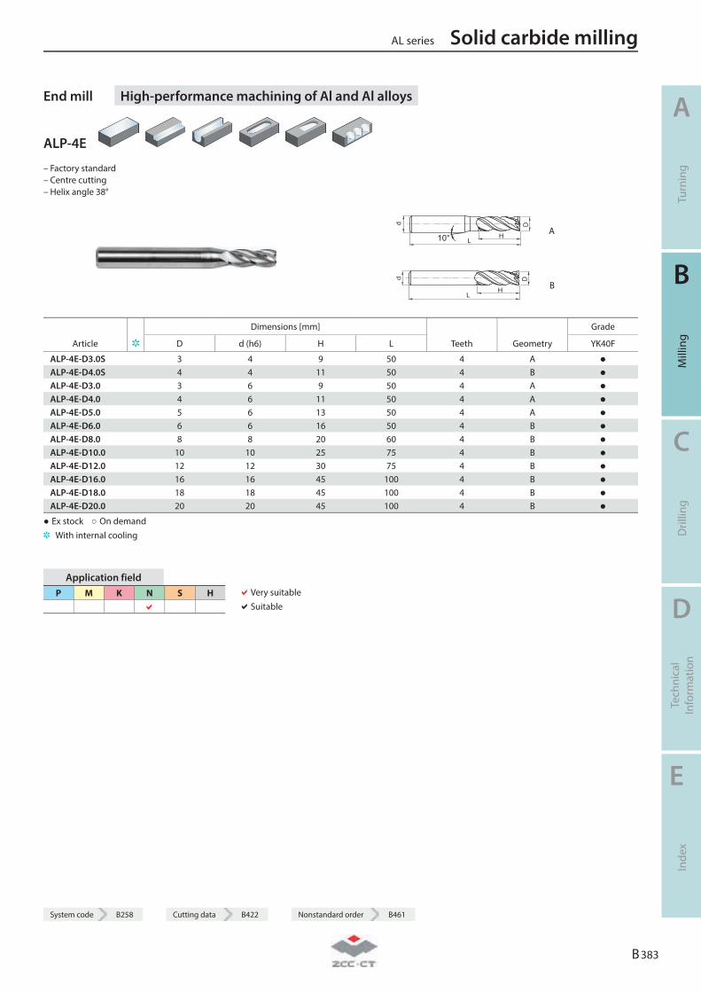
System code B258 Cutting data B422 Nonstandard order B461
End mill High-performance machining of Al and Al alloys
ALP-4E
– Factory standard – Centre cutting – Helix angle 38°
10° HL
Dd
A
HL
Dd
B
Dimensions [mm] Grade
Article D d (h6) H L Teeth Geometry YK40F
ALP-4E-D3.0S 3 4 9 50 4 A ● ALP-4E-D4.0S 4 4 11 50 4 B ● ALP-4E-D3.0 3 6 9 50 4 A ● ALP-4E-D4.0 4 6 11 50 4 A ● ALP-4E-D5.0 5 6 13 50 4 A ● ALP-4E-D6.0 6 6 16 50 4 B ● ALP-4E-D8.0 8 8 20 60 4 B ● ALP-4E-D10.0 10 10 25 75 4 B ● ALP-4E-D12.0 12 12 30 75 4 B ● ALP-4E-D16.0 16 16 45 100 4 B ● ALP-4E-D18.0 18 18 45 100 4 B ● ALP-4E-D20.0 20 20 45 100 4 B ●
● Ex stock ○ On demand With internal cooling
Application field P M K N S H
Very suitable Suitable
AL series Solid carbide milling
A
Turn
ing
B
Mill
ing
C
Dril
ling
D
Tech
nica
l In
form
atio
n
E
Inde
x
B 383
System code B258 Cutting data B422 Nonstandard order B461
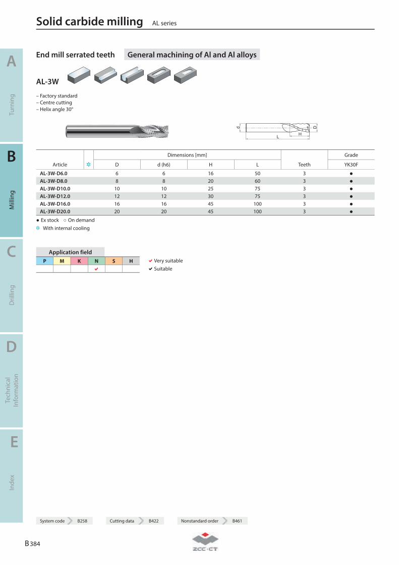
End mill serrated teeth General machining of Al and Al alloys
AL-3W
– Factory standard – Centre cutting – Helix angle 30°
Dimensions [mm] Grade
Article D d (h6) H L Teeth YK30F
AL-3W-D6.0 6 6 16 50 3 ● AL-3W-D8.0 8 8 20 60 3 ● AL-3W-D10.0 10 10 25 75 3 ● AL-3W-D12.0 12 12 30 75 3 ● AL-3W-D16.0 16 16 45 100 3 ● AL-3W-D20.0 20 20 45 100 3 ●
● Ex stock ○ On demand With internal cooling
Application field P M K N S H
Very suitable Suitable
Solid carbide milling AL series
A
Turn
ing
B
Mill
ing
C
Dril
ling
D
Tech
nica
l In
form
atio
n
E
Inde
x
B 384
System code B258 Cutting data B422 Nonstandard order B461
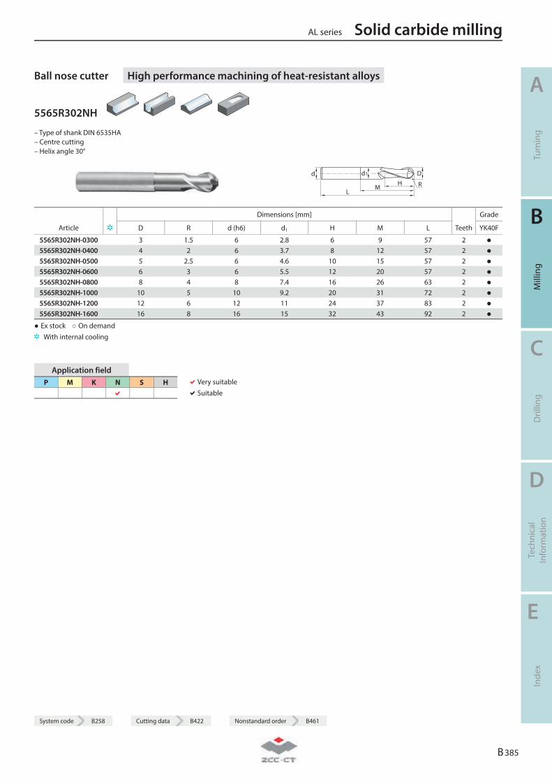
System code B258 Cutting data B422 Nonstandard order B461
Ball nose cutter High performance machining of heat-resistant alloys
5565R302NH
– Type of shank DIN 6535HA – Centre cutting – Helix angle 30°
LM
HDd d1
R
Dimensions [mm] Grade
Article D R d (h6) d1 H M L Teeth YK40F
5565R302NH-0300 3 1.5 6 2.8 6 9 57 2 ● 5565R302NH-0400 4 2 6 3.7 8 12 57 2 ● 5565R302NH-0500 5 2.5 6 4.6 10 15 57 2 ● 5565R302NH-0600 6 3 6 5.5 12 20 57 2 ● 5565R302NH-0800 8 4 8 7.4 16 26 63 2 ● 5565R302NH-1000 10 5 10 9.2 20 31 72 2 ● 5565R302NH-1200 12 6 12 11 24 37 83 2 ● 5565R302NH-1600 16 8 16 15 32 43 92 2 ●
● Ex stock ○ On demand With internal cooling
Application field P M K N S H
Very suitable Suitable
AL series Solid carbide milling
A
Turn
ing
B
Mill
ing
C
Dril
ling
D
Tech
nica
l In
form
atio
n
E
Inde
x
B 385
System code B258 Cutting data B422 Nonstandard order B461
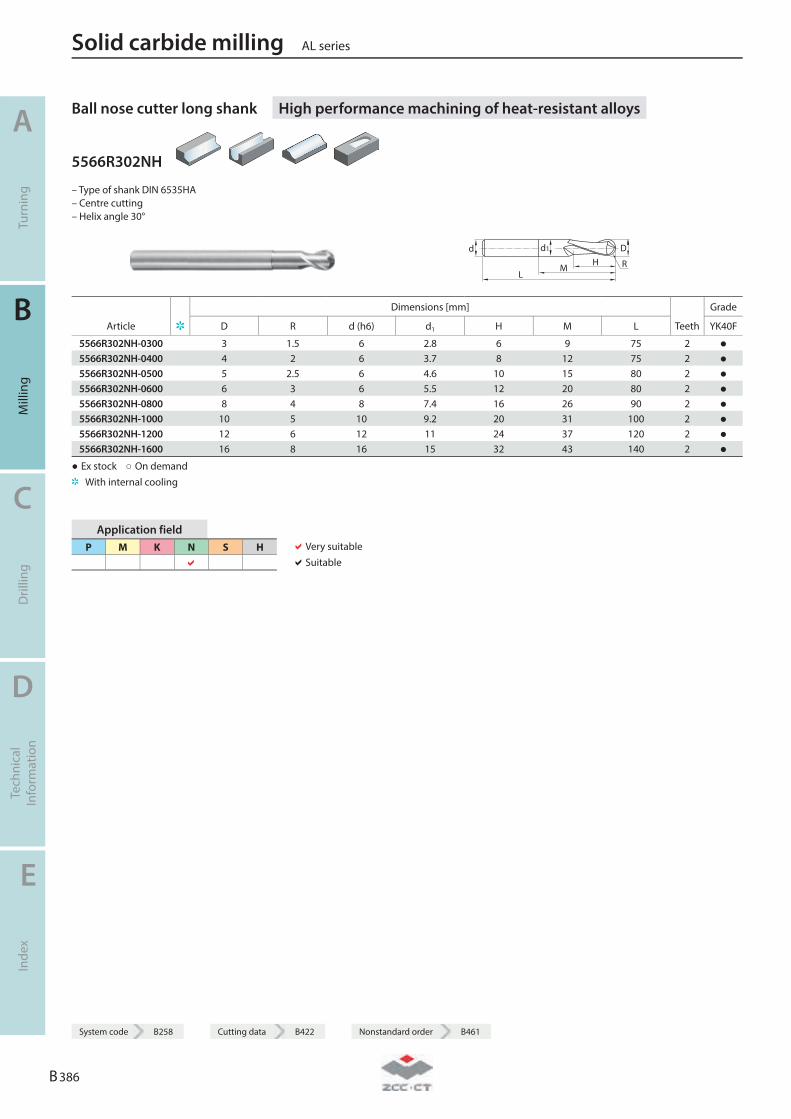
Ball nose cutter long shank High performance machining of heat-resistant alloys
5566R302NH
– Type of shank DIN 6535HA – Centre cutting – Helix angle 30°
LM
HDd d1
R
Dimensions [mm] Grade
Article D R d (h6) d1 H M L Teeth YK40F
5566R302NH-0300 3 1.5 6 2.8 6 9 75 2 ● 5566R302NH-0400 4 2 6 3.7 8 12 75 2 ● 5566R302NH-0500 5 2.5 6 4.6 10 15 80 2 ● 5566R302NH-0600 6 3 6 5.5 12 20 80 2 ● 5566R302NH-0800 8 4 8 7.4 16 26 90 2 ● 5566R302NH-1000 10 5 10 9.2 20 31 100 2 ● 5566R302NH-1200 12 6 12 11 24 37 120 2 ● 5566R302NH-1600 16 8 16 15 32 43 140 2 ●
● Ex stock ○ On demand With internal cooling
Application field P M K N S H
Very suitable Suitable
Solid carbide milling AL series
A
Turn
ing
B
Mill
ing
C
Dril
ling
D
Tech
nica
l In
form
atio
n
E
Inde
x
B 386
System code B258 Cutting data B422 Nonstandard order B461
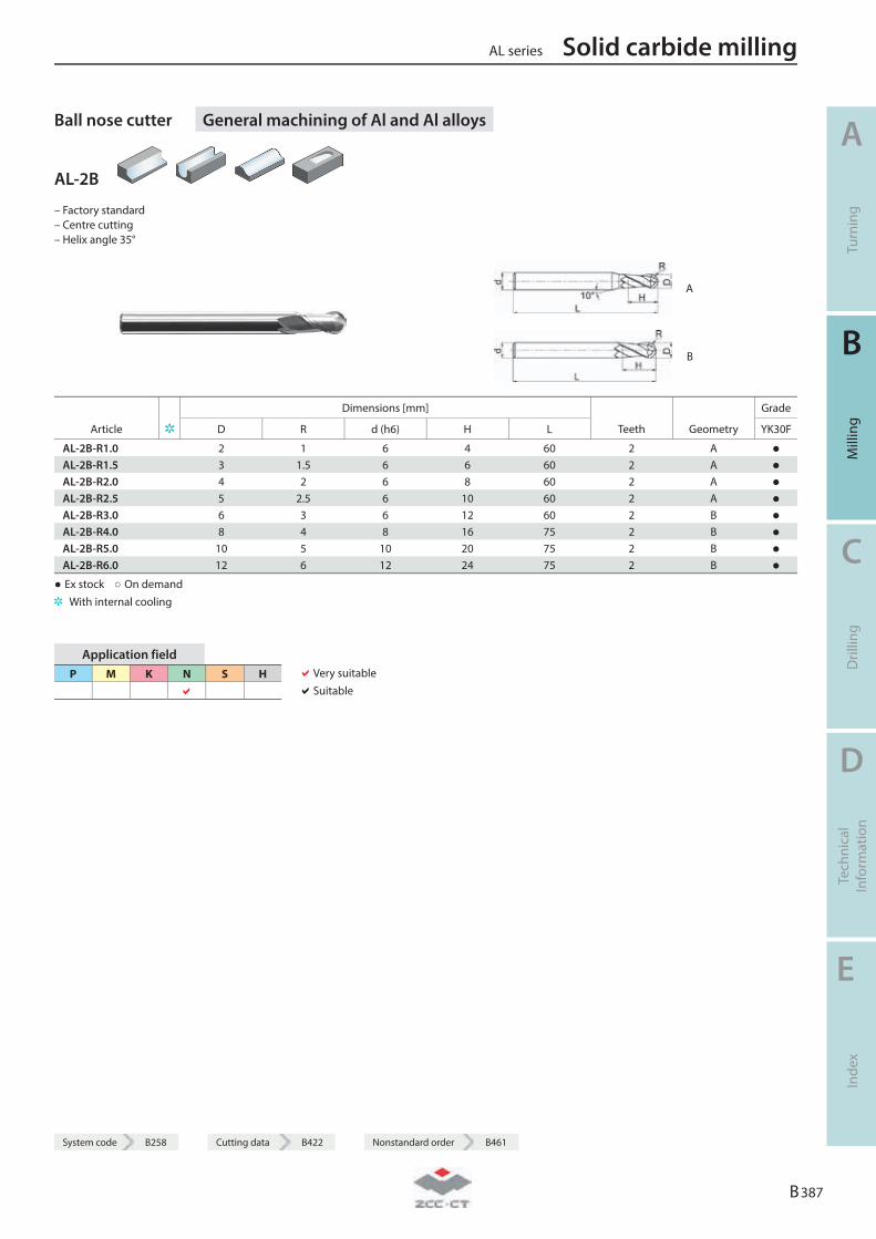
System code B258 Cutting data B422 Nonstandard order B461
Ball nose cutter General machining of Al and Al alloys
AL-2B
– Factory standard – Centre cutting – Helix angle 35°
A
B
Dimensions [mm] Grade
Article D R d (h6) H L Teeth Geometry YK30F
AL-2B-R1.0 2 1 6 4 60 2 A ● AL-2B-R1.5 3 1.5 6 6 60 2 A ● AL-2B-R2.0 4 2 6 8 60 2 A ● AL-2B-R2.5 5 2.5 6 10 60 2 A ● AL-2B-R3.0 6 3 6 12 60 2 B ● AL-2B-R4.0 8 4 8 16 75 2 B ● AL-2B-R5.0 10 5 10 20 75 2 B ● AL-2B-R6.0 12 6 12 24 75 2 B ●
● Ex stock ○ On demand With internal cooling
Application field P M K N S H
Very suitable Suitable
AL series Solid carbide milling
A
Turn
ing
B
Mill
ing
C
Dril
ling
D
Tech
nica
l In
form
atio
n
E
Inde
x
B 387
System code B258 Cutting data B422 Nonstandard order B461
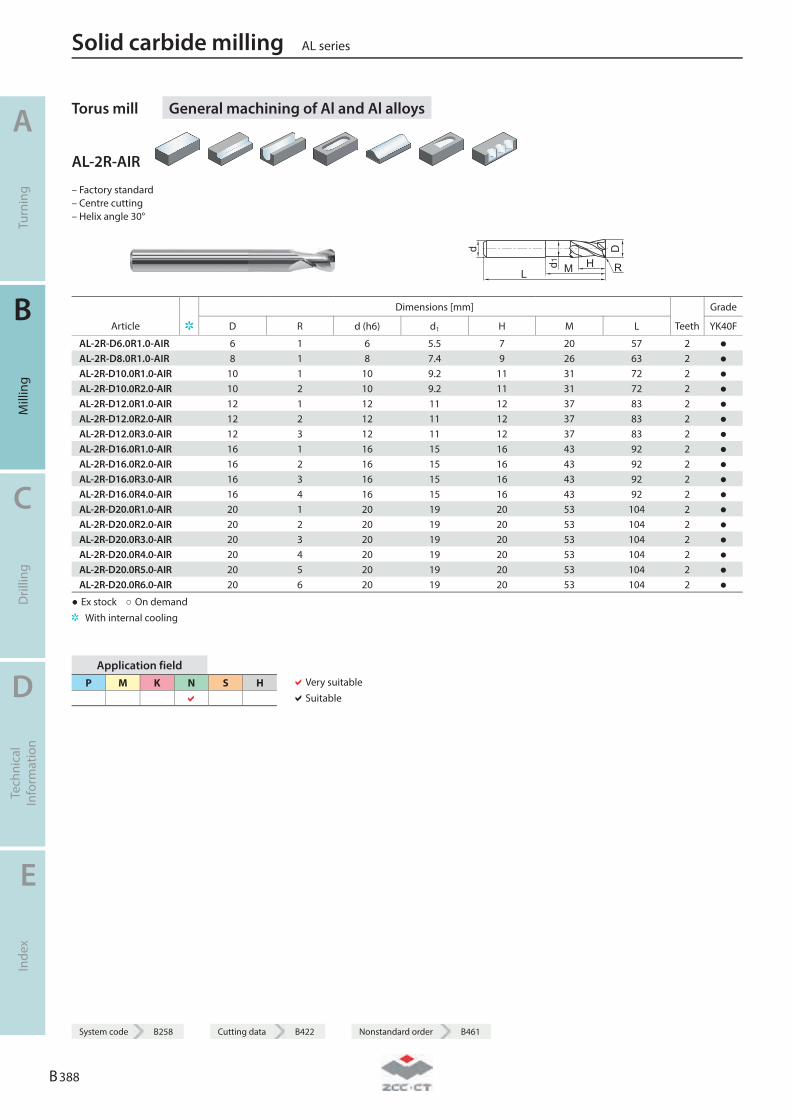
Torus mill General machining of Al and Al alloys
AL-2R-AIR
– Factory standard – Centre cutting – Helix angle 30°
R
Dimensions [mm] Grade
Article D R d (h6) d1 H M L Teeth YK40F
AL-2R-D6.0R1.0-AIR 6 1 6 5.5 7 20 57 2 ● AL-2R-D8.0R1.0-AIR 8 1 8 7.4 9 26 63 2 ● AL-2R-D10.0R1.0-AIR 10 1 10 9.2 11 31 72 2 ● AL-2R-D10.0R2.0-AIR 10 2 10 9.2 11 31 72 2 ● AL-2R-D12.0R1.0-AIR 12 1 12 11 12 37 83 2 ● AL-2R-D12.0R2.0-AIR 12 2 12 11 12 37 83 2 ● AL-2R-D12.0R3.0-AIR 12 3 12 11 12 37 83 2 ● AL-2R-D16.0R1.0-AIR 16 1 16 15 16 43 92 2 ● AL-2R-D16.0R2.0-AIR 16 2 16 15 16 43 92 2 ● AL-2R-D16.0R3.0-AIR 16 3 16 15 16 43 92 2 ● AL-2R-D16.0R4.0-AIR 16 4 16 15 16 43 92 2 ● AL-2R-D20.0R1.0-AIR 20 1 20 19 20 53 104 2 ● AL-2R-D20.0R2.0-AIR 20 2 20 19 20 53 104 2 ● AL-2R-D20.0R3.0-AIR 20 3 20 19 20 53 104 2 ● AL-2R-D20.0R4.0-AIR 20 4 20 19 20 53 104 2 ● AL-2R-D20.0R5.0-AIR 20 5 20 19 20 53 104 2 ● AL-2R-D20.0R6.0-AIR 20 6 20 19 20 53 104 2 ●
● Ex stock ○ On demand With internal cooling
Application field P M K N S H
Very suitable Suitable
Solid carbide milling AL series
A
Turn
ing
B
Mill
ing
C
Dril
ling
D
Tech
nica
l In
form
atio
n
E
Inde
x
B 388
System code B258 Cutting data B422 Nonstandard order B461
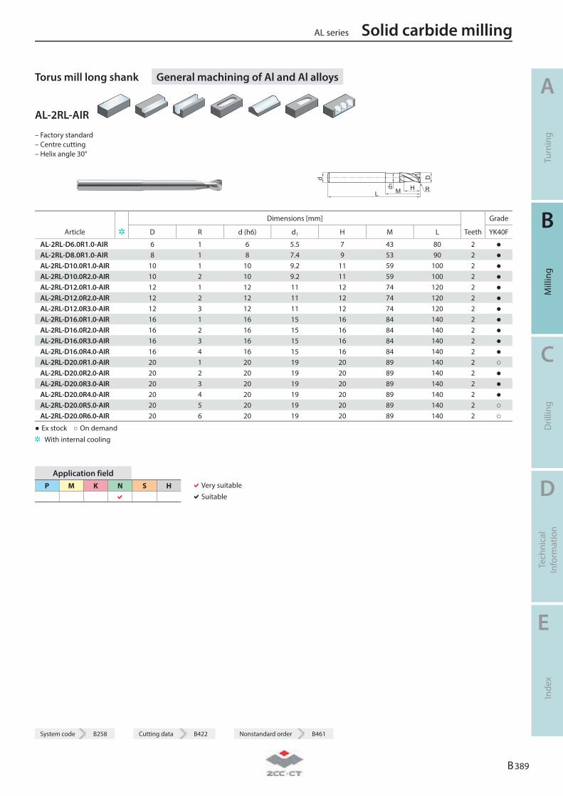
System code B258 Cutting data B422 Nonstandard order B461
Torus mill long shank General machining of Al and Al alloys
AL-2RL-AIR
– Factory standard – Centre cutting – Helix angle 30°
R
Dimensions [mm] Grade
Article D R d (h6) d1 H M L Teeth YK40F
AL-2RL-D6.0R1.0-AIR 6 1 6 5.5 7 43 80 2 ● AL-2RL-D8.0R1.0-AIR 8 1 8 7.4 9 53 90 2 ● AL-2RL-D10.0R1.0-AIR 10 1 10 9.2 11 59 100 2 ● AL-2RL-D10.0R2.0-AIR 10 2 10 9.2 11 59 100 2 ● AL-2RL-D12.0R1.0-AIR 12 1 12 11 12 74 120 2 ● AL-2RL-D12.0R2.0-AIR 12 2 12 11 12 74 120 2 ● AL-2RL-D12.0R3.0-AIR 12 3 12 11 12 74 120 2 ● AL-2RL-D16.0R1.0-AIR 16 1 16 15 16 84 140 2 ● AL-2RL-D16.0R2.0-AIR 16 2 16 15 16 84 140 2 ● AL-2RL-D16.0R3.0-AIR 16 3 16 15 16 84 140 2 ● AL-2RL-D16.0R4.0-AIR 16 4 16 15 16 84 140 2 ● AL-2RL-D20.0R1.0-AIR 20 1 20 19 20 89 140 2 ○ AL-2RL-D20.0R2.0-AIR 20 2 20 19 20 89 140 2 ● AL-2RL-D20.0R3.0-AIR 20 3 20 19 20 89 140 2 ● AL-2RL-D20.0R4.0-AIR 20 4 20 19 20 89 140 2 ● AL-2RL-D20.0R5.0-AIR 20 5 20 19 20 89 140 2 ○ AL-2RL-D20.0R6.0-AIR 20 6 20 19 20 89 140 2 ○
● Ex stock ○ On demand With internal cooling
Application field P M K N S H
Very suitable Suitable
AL series Solid carbide milling
A
Turn
ing
B
Mill
ing
C
Dril
ling
D
Tech
nica
l In
form
atio
n
E
Inde
x
B 389
System code B258 Cutting data B422 Nonstandard order B461
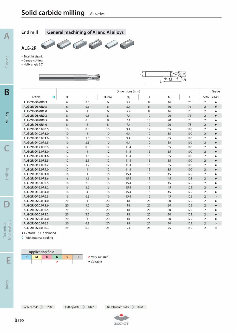
End mill General machining of Al and Al alloys
ALG-2R
– Straight shank – Centre cutting – Helix angle 30°
R
Dimensions [mm] Grade
Article D R d (h6) d1 H M L Teeth YK40F
ALG-2R-D6.0R0.3 6 0.3 6 5.7 8 16 75 2 ● ALG-2R-D6.0R0.5 6 0.5 6 5.7 8 16 75 2 ● ALG-2R-D6.0R1.0 6 1 6 5.7 8 16 75 2 ● ALG-2R-D8.0R0.3 8 0.3 8 7.4 10 20 75 2 ● ALG-2R-D8.0R0.5 8 0.5 8 7.4 10 20 75 2 ● ALG-2R-D8.0R1.0 8 1 8 7.4 10 20 75 2 ● ALG-2R-D10.0R0.5 10 0.5 10 9.4 12 35 100 2 ● ALG-2R-D10.0R1.0 10 1 10 9.4 12 35 100 2 ● ALG-2R-D10.0R1.6 10 1.6 10 9.4 12 35 100 2 ● ALG-2R-D10.0R2.5 10 2.5 10 9.4 12 35 100 2 ● ALG-2R-D12.0R0.5 12 0.5 12 11.4 15 35 100 2 ● ALG-2R-D12.0R1.0 12 1 12 11.4 15 35 100 2 ● ALG-2R-D12.0R1.6 12 1.6 12 11.4 15 35 100 2 ● ALG-2R-D12.0R2.5 12 2.5 12 11.4 15 35 100 2 ● ALG-2R-D12.0R3.2 12 3.2 12 11.4 15 35 100 2 ● ALG-2R-D12.0R4.0 12 4 12 11.4 15 35 100 2 ● ALG-2R-D16.0R1.0 16 1 16 15.4 15 45 125 2 ● ALG-2R-D16.0R1.6 16 1.6 16 15.4 15 45 125 2 ● ALG-2R-D16.0R2.5 16 2.5 16 15.4 15 45 125 2 ● ALG-2R-D16.0R3.2 16 3.2 16 15.4 15 45 125 2 ● ALG-2R-D16.0R4.0 16 4 16 15.4 15 45 125 2 ● ALG-2R-D16.0R6.3 16 6.3 16 15.4 15 45 125 2 ○ ALG-2R-D20.0R1.0 20 1 20 18 20 50 125 2 ● ALG-2R-D20.0R1.6 20 1.6 20 18 20 50 125 2 ● ALG-2R-D20.0R2.5 20 2.5 20 18 20 50 125 2 ● ALG-2R-D20.0R3.2 20 3.2 20 18 20 50 125 2 ● ALG-2R-D20.0R4.0 20 4 20 18 20 50 125 2 ● ALG-2R-D20.0R6.3 20 6.3 20 18 20 50 125 2 ○ ALG-2R-D25.0R6.3 25 6.3 25 23 25 75 150 2 ○
● Ex stock ○ On demand With internal cooling
Application field P M K N S H
Very suitable Suitable
Solid carbide milling AL series
A
Turn
ing
B
Mill
ing
C
Dril
ling
D
Tech
nica
l In
form
atio
n
E
Inde
x
B 390
System code B258 Cutting data B422 Nonstandard order B461

System code B258 Cutting data B422 Nonstandard order B461
Torus mill General machining of Al and Al alloys
AL-3R-AIR
– Factory standard – Centre cutting – Helix angle 30°
R
Dimensions [mm] Grade
Article D R d (h6) d1 H M L Teeth YK40F
AL-3R-D12.0R1.0-AIR 12 1 12 11 12 37 83 3 ● AL-3R-D12.0R2.0-AIR 12 2 12 11 12 37 83 3 ● AL-3R-D12.0R3.0-AIR 12 3 12 11 12 37 83 3 ● AL-3R-D16.0R1.0-AIR 16 1 16 15 16 43 92 3 ● AL-3R-D16.0R2.0-AIR 16 2 16 15 16 43 92 3 ● AL-3R-D16.0R3.0-AIR 16 3 16 15 16 43 92 3 ● AL-3R-D16.0R4.0-AIR 16 4 16 15 16 43 92 3 ● AL-3R-D20.0R1.0-AIR 20 1 20 19 20 53 104 3 ● AL-3R-D20.0R2.0-AIR 20 2 20 19 20 53 104 3 ○ AL-3R-D20.0R3.0-AIR 20 3 20 19 20 53 104 3 ○ AL-3R-D20.0R4.0-AIR 20 4 20 19 20 53 104 3 ○ AL-3R-D20.0R5.0-AIR 20 5 20 19 20 53 104 3 ● AL-3R-D20.0R6.0-AIR 20 6 20 19 20 53 104 3 ○
● Ex stock ○ On demand With internal cooling
Application field P M K N S H
Very suitable Suitable
AL series Solid carbide milling
A
Turn
ing
B
Mill
ing
C
Dril
ling
D
Tech
nica
l In
form
atio
n
E
Inde
x
B 391
System code B258 Cutting data B422 Nonstandard order B461
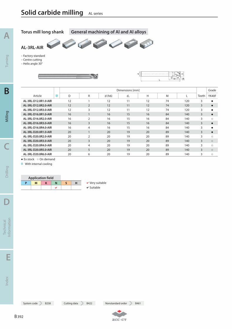
Torus mill long shank General machining of Al and Al alloys
AL-3RL-AIR
– Factory standard – Centre cutting – Helix angle 30°
R
Dimensions [mm] Grade
Article D R d (h6) d1 H M L Teeth YK40F
AL-3RL-D12.0R1.0-AIR 12 1 12 11 12 74 120 3 ● AL-3RL-D12.0R2.0-AIR 12 2 12 11 12 74 120 3 ● AL-3RL-D12.0R3.0-AIR 12 3 12 11 12 74 120 3 ● AL-3RL-D16.0R1.0-AIR 16 1 16 15 16 84 140 3 ● AL-3RL-D16.0R2.0-AIR 16 2 16 15 16 84 140 3 ○ AL-3RL-D16.0R3.0-AIR 16 3 16 15 16 84 140 3 ● AL-3RL-D16.0R4.0-AIR 16 4 16 15 16 84 140 3 ● AL-3RL-D20.0R1.0-AIR 20 1 20 19 20 89 140 3 ● AL-3RL-D20.0R2.0-AIR 20 2 20 19 20 89 140 3 ○ AL-3RL-D20.0R3.0-AIR 20 3 20 19 20 89 140 3 ○ AL-3RL-D20.0R4.0-AIR 20 4 20 19 20 89 140 3 ○ AL-3RL-D20.0R5.0-AIR 20 5 20 19 20 89 140 3 ○ AL-3RL-D20.0R6.0-AIR 20 6 20 19 20 89 140 3 ○
● Ex stock ○ On demand With internal cooling
Application field P M K N S H
Very suitable Suitable
Solid carbide milling AL series
A
Turn
ing
B
Mill
ing
C
Dril
ling
D
Tech
nica
l In
form
atio
n
E
Inde
x
B 392
System code B258 Cutting data B422 Nonstandard order B461
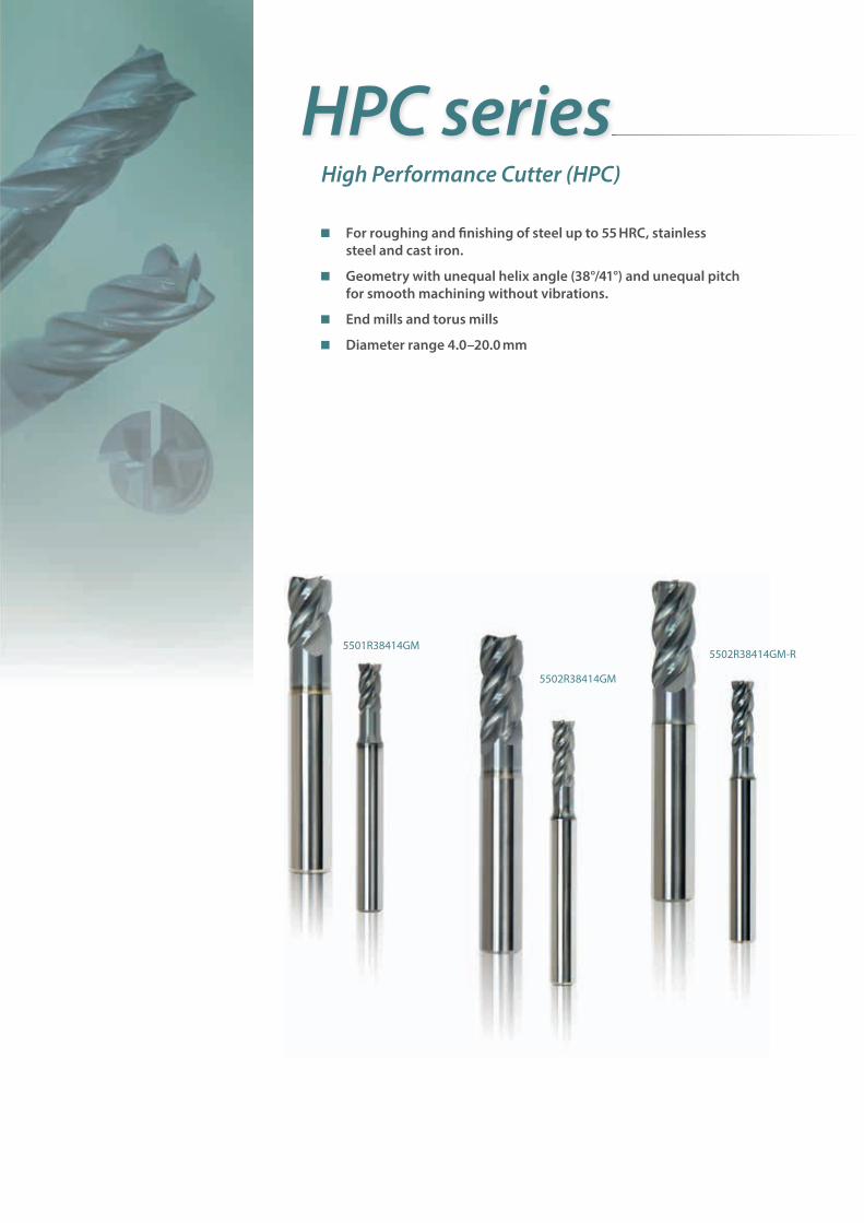
For roughing and fi nishing of steel up to 55 HRC, stainless steel and cast iron.
Geometry with unequal helix angle (38°/41°) and unequal pitch for smooth machining without vibrations.
End mills and torus mills
Diameter range 4.0–20.0 mm
HPC seriesHigh Performance Cutter (HPC)
5502R38414GM
5502R38414GM-R5501R38414GM
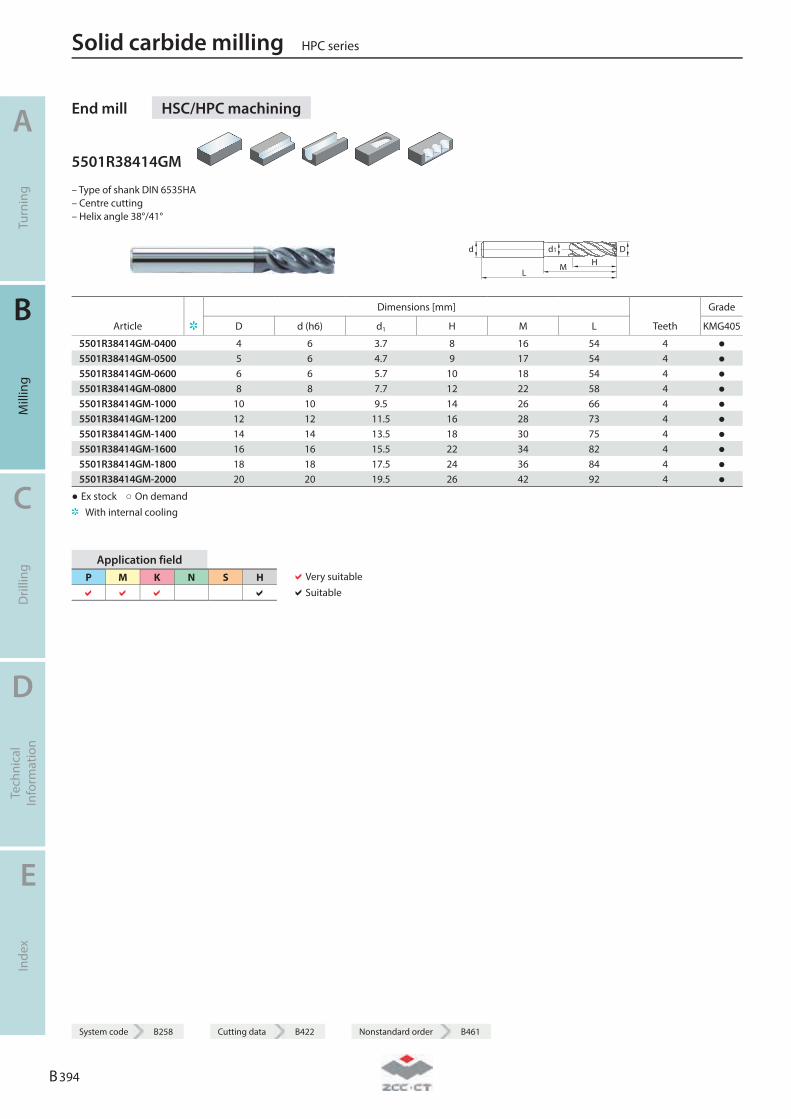
End mill HSC/HPC machining
5501R38414GM
– Type of shank DIN 6535HA – Centre cutting – Helix angle 38°/41°
LM H
Dd d1
Dimensions [mm] Grade
Article D d (h6) d1 H M L Teeth KMG405
5501R38414GM-0400 4 6 3.7 8 16 54 4 ● 5501R38414GM-0500 5 6 4.7 9 17 54 4 ● 5501R38414GM-0600 6 6 5.7 10 18 54 4 ● 5501R38414GM-0800 8 8 7.7 12 22 58 4 ● 5501R38414GM-1000 10 10 9.5 14 26 66 4 ● 5501R38414GM-1200 12 12 11.5 16 28 73 4 ● 5501R38414GM-1400 14 14 13.5 18 30 75 4 ● 5501R38414GM-1600 16 16 15.5 22 34 82 4 ● 5501R38414GM-1800 18 18 17.5 24 36 84 4 ● 5501R38414GM-2000 20 20 19.5 26 42 92 4 ●
● Ex stock ○ On demand With internal cooling
Application field P M K N S H
Very suitable Suitable
Solid carbide milling HPC series
A
Turn
ing
B
Mill
ing
C
Dril
ling
D
Tech
nica
l In
form
atio
n
E
Inde
x
B 394
System code B258 Cutting data B422 Nonstandard order B461
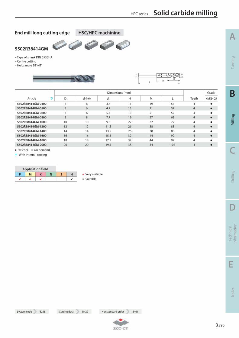
System code B258 Cutting data B422 Nonstandard order B461
End mill long cutting edge HSC/HPC machining
5502R38414GM
– Type of shank DIN 6535HA – Centre cutting – Helix angle 38°/41°
LM H
Dd d1
Dimensions [mm] Grade
Article D d (h6) d1 H M L Teeth KMG405
5502R38414GM-0400 4 6 3.7 11 19 57 4 ● 5502R38414GM-0500 5 6 4.7 13 21 57 4 ● 5502R38414GM-0600 6 6 5.7 13 21 57 4 ● 5502R38414GM-0800 8 8 7.7 19 27 63 4 ● 5502R38414GM-1000 10 10 9.5 22 32 72 4 ● 5502R38414GM-1200 12 12 11.5 26 38 83 4 ● 5502R38414GM-1400 14 14 13.5 26 38 83 4 ● 5502R38414GM-1600 16 16 15.5 32 44 92 4 ● 5502R38414GM-1800 18 18 17.5 32 44 92 4 ● 5502R38414GM-2000 20 20 19.5 38 54 104 4 ●
● Ex stock ○ On demand With internal cooling
Application field P M K N S H
Very suitable Suitable
HPC series Solid carbide milling
A
Turn
ing
B
Mill
ing
C
Dril
ling
D
Tech
nica
l In
form
atio
n
E
Inde
x
B 395
System code B258 Cutting data B422 Nonstandard order B461
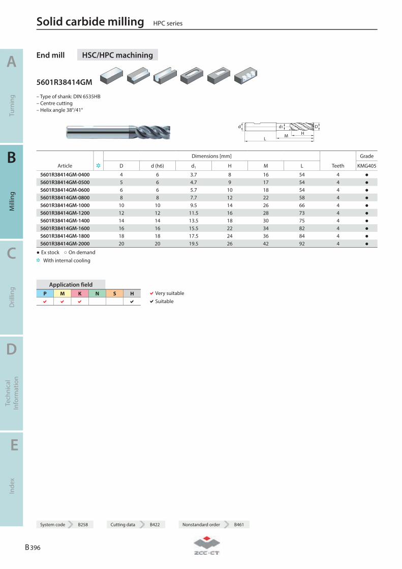
End mill HSC/HPC machining
5601R38414GM
– Type of shank: DIN 6535HB – Centre cutting – Helix angle 38°/41°
LM H
Dd d1
Dimensions [mm] Grade
Article D d (h6) d1 H M L Teeth KMG405
5601R38414GM-0400 4 6 3.7 8 16 54 4 ● 5601R38414GM-0500 5 6 4.7 9 17 54 4 ● 5601R38414GM-0600 6 6 5.7 10 18 54 4 ● 5601R38414GM-0800 8 8 7.7 12 22 58 4 ● 5601R38414GM-1000 10 10 9.5 14 26 66 4 ● 5601R38414GM-1200 12 12 11.5 16 28 73 4 ● 5601R38414GM-1400 14 14 13.5 18 30 75 4 ● 5601R38414GM-1600 16 16 15.5 22 34 82 4 ● 5601R38414GM-1800 18 18 17.5 24 36 84 4 ● 5601R38414GM-2000 20 20 19.5 26 42 92 4 ●
● Ex stock ○ On demand With internal cooling
Application field P M K N S H
Very suitable Suitable
Solid carbide milling HPC series
A
Turn
ing
B
Mill
ing
C
Dril
ling
D
Tech
nica
l In
form
atio
n
E
Inde
x
B 396
System code B258 Cutting data B422 Nonstandard order B461
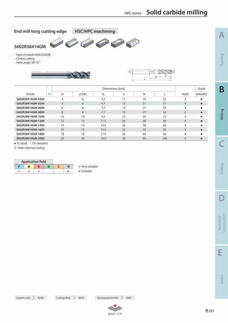
System code B258 Cutting data B422 Nonstandard order B461
End mill long cutting edge HSC/HPC machining
5602R38414GM
– Type of shank: DIN 6535HB – Centre cutting – Helix angle 38°/41°
LM
HDd d1
Dimensions [mm] Grade
Article D d (h6) d1 H M L Teeth KMG405
5602R38414GM-0400 4 6 3.7 11 19 57 4 ● 5602R38414GM-0500 5 6 4.7 13 21 57 4 ● 5602R38414GM-0600 6 6 5.7 13 21 57 4 ● 5602R38414GM-0800 8 8 7.7 19 27 63 4 ● 5602R38414GM-1000 10 10 9.5 22 32 72 4 ● 5602R38414GM-1200 12 12 11.5 26 38 83 4 ● 5602R38414GM-1400 14 14 13.5 26 38 83 4 ● 5602R38414GM-1600 16 16 15.5 32 44 92 4 ● 5602R38414GM-1800 18 18 17.5 32 44 92 4 ● 5602R38414GM-2000 20 20 19.5 38 54 104 4 ●
● Ex stock ○ On demand With internal cooling
Application field P M K N S H
Very suitable Suitable
HPC series Solid carbide milling
A
Turn
ing
B
Mill
ing
C
Dril
ling
D
Tech
nica
l In
form
atio
n
E
Inde
x
B 397
System code B258 Cutting data B422 Nonstandard order B461
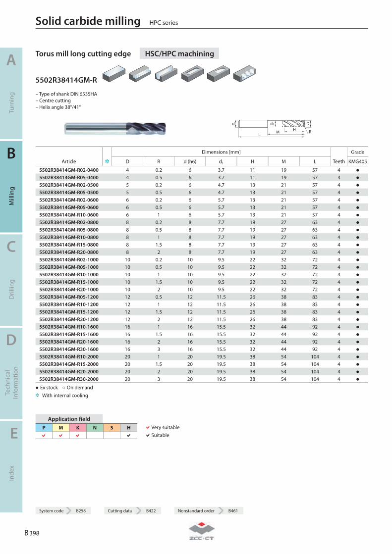
Torus mill long cutting edge HSC/HPC machining
5502R38414GM-R
– Type of shank DIN 6535HA – Centre cutting – Helix angle 38°/41°
LM H
Dd d1
R
Dimensions [mm] Grade
Article D R d (h6) d1 H M L Teeth KMG405
5502R38414GM-R02-0400 4 0.2 6 3.7 11 19 57 4 ● 5502R38414GM-R05-0400 4 0.5 6 3.7 11 19 57 4 ● 5502R38414GM-R02-0500 5 0.2 6 4.7 13 21 57 4 ● 5502R38414GM-R05-0500 5 0.5 6 4.7 13 21 57 4 ● 5502R38414GM-R02-0600 6 0.2 6 5.7 13 21 57 4 ● 5502R38414GM-R05-0600 6 0.5 6 5.7 13 21 57 4 ● 5502R38414GM-R10-0600 6 1 6 5.7 13 21 57 4 ● 5502R38414GM-R02-0800 8 0.2 8 7.7 19 27 63 4 ● 5502R38414GM-R05-0800 8 0.5 8 7.7 19 27 63 4 ● 5502R38414GM-R10-0800 8 1 8 7.7 19 27 63 4 ● 5502R38414GM-R15-0800 8 1.5 8 7.7 19 27 63 4 ● 5502R38414GM-R20-0800 8 2 8 7.7 19 27 63 4 ● 5502R38414GM-R02-1000 10 0.2 10 9.5 22 32 72 4 ● 5502R38414GM-R05-1000 10 0.5 10 9.5 22 32 72 4 ● 5502R38414GM-R10-1000 10 1 10 9.5 22 32 72 4 ● 5502R38414GM-R15-1000 10 1.5 10 9.5 22 32 72 4 ● 5502R38414GM-R20-1000 10 2 10 9.5 22 32 72 4 ● 5502R38414GM-R05-1200 12 0.5 12 11.5 26 38 83 4 ● 5502R38414GM-R10-1200 12 1 12 11.5 26 38 83 4 ● 5502R38414GM-R15-1200 12 1.5 12 11.5 26 38 83 4 ● 5502R38414GM-R20-1200 12 2 12 11.5 26 38 83 4 ● 5502R38414GM-R10-1600 16 1 16 15.5 32 44 92 4 ● 5502R38414GM-R15-1600 16 1.5 16 15.5 32 44 92 4 ● 5502R38414GM-R20-1600 16 2 16 15.5 32 44 92 4 ● 5502R38414GM-R30-1600 16 3 16 15.5 32 44 92 4 ● 5502R38414GM-R10-2000 20 1 20 19.5 38 54 104 4 ● 5502R38414GM-R15-2000 20 1.5 20 19.5 38 54 104 4 ● 5502R38414GM-R20-2000 20 2 20 19.5 38 54 104 4 ● 5502R38414GM-R30-2000 20 3 20 19.5 38 54 104 4 ●
● Ex stock ○ On demand With internal cooling
Application field P M K N S H
Very suitable Suitable
Solid carbide milling HPC series
A
Turn
ing
B
Mill
ing
C
Dril
ling
D
Tech
nica
l In
form
atio
n
E
Inde
x
B 398
System code B258 Cutting data B422 Nonstandard order B461
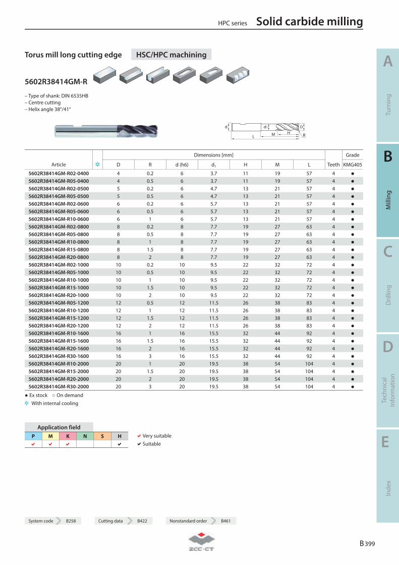
System code B258 Cutting data B422 Nonstandard order B461
Torus mill long cutting edge HSC/HPC machining
5602R38414GM-R
– Type of shank: DIN 6535HB – Centre cutting – Helix angle 38°/41°
L M HDd d1
R
Dimensions [mm] Grade
Article D R d (h6) d1 H M L Teeth KMG405
5602R38414GM-R02-0400 4 0.2 6 3.7 11 19 57 4 ● 5602R38414GM-R05-0400 4 0.5 6 3.7 11 19 57 4 ● 5602R38414GM-R02-0500 5 0.2 6 4.7 13 21 57 4 ● 5602R38414GM-R05-0500 5 0.5 6 4.7 13 21 57 4 ● 5602R38414GM-R02-0600 6 0.2 6 5.7 13 21 57 4 ● 5602R38414GM-R05-0600 6 0.5 6 5.7 13 21 57 4 ● 5602R38414GM-R10-0600 6 1 6 5.7 13 21 57 4 ● 5602R38414GM-R02-0800 8 0.2 8 7.7 19 27 63 4 ● 5602R38414GM-R05-0800 8 0.5 8 7.7 19 27 63 4 ● 5602R38414GM-R10-0800 8 1 8 7.7 19 27 63 4 ● 5602R38414GM-R15-0800 8 1.5 8 7.7 19 27 63 4 ● 5602R38414GM-R20-0800 8 2 8 7.7 19 27 63 4 ● 5602R38414GM-R02-1000 10 0.2 10 9.5 22 32 72 4 ● 5602R38414GM-R05-1000 10 0.5 10 9.5 22 32 72 4 ● 5602R38414GM-R10-1000 10 1 10 9.5 22 32 72 4 ● 5602R38414GM-R15-1000 10 1.5 10 9.5 22 32 72 4 ● 5602R38414GM-R20-1000 10 2 10 9.5 22 32 72 4 ● 5602R38414GM-R05-1200 12 0.5 12 11.5 26 38 83 4 ● 5602R38414GM-R10-1200 12 1 12 11.5 26 38 83 4 ● 5602R38414GM-R15-1200 12 1.5 12 11.5 26 38 83 4 ● 5602R38414GM-R20-1200 12 2 12 11.5 26 38 83 4 ● 5602R38414GM-R10-1600 16 1 16 15.5 32 44 92 4 ● 5602R38414GM-R15-1600 16 1.5 16 15.5 32 44 92 4 ● 5602R38414GM-R20-1600 16 2 16 15.5 32 44 92 4 ● 5602R38414GM-R30-1600 16 3 16 15.5 32 44 92 4 ● 5602R38414GM-R10-2000 20 1 20 19.5 38 54 104 4 ● 5602R38414GM-R15-2000 20 1.5 20 19.5 38 54 104 4 ● 5602R38414GM-R20-2000 20 2 20 19.5 38 54 104 4 ● 5602R38414GM-R30-2000 20 3 20 19.5 38 54 104 4 ●
● Ex stock ○ On demand With internal cooling
Application field P M K N S H
Very suitable Suitable
HPC series Solid carbide milling
A
Turn
ing
B
Mill
ing
C
Dril
ling
D
Tech
nica
l In
form
atio
n
E
Inde
x
B 399
System code B258 Cutting data B422 Nonstandard order B461
Solid carbide milling HPC series
A
Turn
ing
B
Mill
ing
C
Dril
ling
D
Tech
nica
l In
form
atio
n
E
Inde
x
B 400
Notes
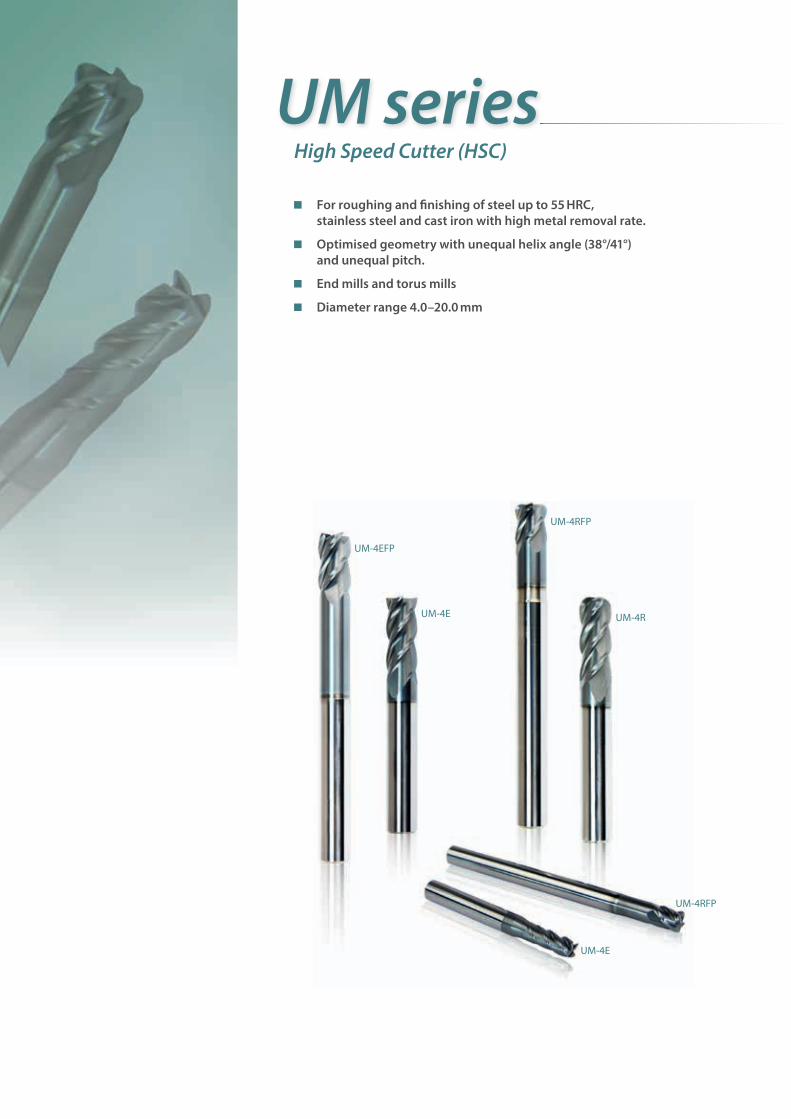
For roughing and fi nishing of steel up to 55 HRC, stainless steel and cast iron with high metal removal rate.
Optimised geometry with unequal helix angle (38°/41°) and unequal pitch.
End mills and torus mills
Diameter range 4.0–20.0 mm
UM seriesHigh Speed Cutter (HSC)
UM-4R
UM-4E
UM-4EFP
UM-4E
UM-4RFP
UM-4RFP
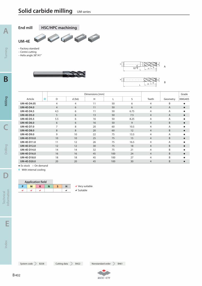
End mill HSC/HPC machining
UM-4E
– Factory standard – Centre cutting – Helix angle 38°/41°
10° HLS
Dd
A
HLS
Dd
B
Dimensions [mm] Grade
Article D d (h6) H L S Teeth Geometry KMG405
UM-4E-D4.0S 4 4 11 50 6 4 B ● UM-4E-D4.0 4 6 11 50 6 4 A ● UM-4E-D4.5 4.5 6 11 50 6.75 4 A ● UM-4E-D5.0 5 6 13 50 7.5 4 A ● UM-4E-D5.5 5.5 6 16 50 8.25 4 A ● UM-4E-D6.0 6 6 16 50 9 4 B ● UM-4E-D7.0 7 8 20 60 10.5 4 A ● UM-4E-D8.0 8 8 20 60 12 4 B ● UM-4E-D9.0 9 10 22 75 13.5 4 A ● UM-4E-D10.0 10 10 25 75 15 4 B ● UM-4E-D11.0 11 12 26 75 16.5 4 A ● UM-4E-D12.0 12 12 30 75 18 4 B ● UM-4E-D14.0 14 14 32 75 21 4 B ● UM-4E-D16.0 16 16 45 100 24 4 B ● UM-4E-D18.0 18 18 45 100 27 4 B ● UM-4E-D20.0 20 20 45 100 30 4 B ●
● Ex stock ○ On demand With internal cooling
Application field P M K N S H
Very suitable Suitable
Solid carbide milling UM series
A
Turn
ing
B
Mill
ing
C
Dril
ling
D
Tech
nica
l In
form
atio
n
E
Inde
x
B 402
System code B258 Cutting data B422 Nonstandard order B461
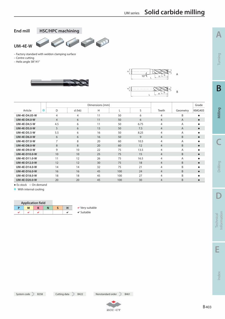
System code B258 Cutting data B422 Nonstandard order B461
End mill HSC/HPC machining
UM-4E-W
– Factory standard with weldon clamping surface – Centre cutting – Helix angle 38°/41°
10° HLS
Dd
A
HLS
Dd
B
Dimensions [mm] Grade
Article D d (h6) H L S Teeth Geometry KMG405
UM-4E-D4.0S-W 4 4 11 50 6 4 B ● UM-4E-D4.0-W 4 6 11 50 6 4 A ● UM-4E-D4.5-W 4.5 6 11 50 6.75 4 A ● UM-4E-D5.0-W 5 6 13 50 7.5 4 A ● UM-4E-D5.5-W 5.5 6 16 50 8.25 4 A ● UM-4E-D6.0-W 6 6 16 50 9 4 B ● UM-4E-D7.0-W 7 8 20 60 10.5 4 A ● UM-4E-D8.0-W 8 8 20 60 12 4 B ● UM-4E-D9.0-W 9 10 22 75 13.5 4 A ● UM-4E-D10.0-W 10 10 25 75 15 4 B ● UM-4E-D11.0-W 11 12 26 75 16.5 4 A ● UM-4E-D12.0-W 12 12 30 75 18 4 B ● UM-4E-D14.0-W 14 14 32 75 21 4 B ● UM-4E-D16.0-W 16 16 45 100 24 4 B ● UM-4E-D18.0-W 18 18 45 100 27 4 B ● UM-4E-D20.0-W 20 20 45 100 30 4 B ●
● Ex stock ○ On demand With internal cooling
Application field P M K N S H
Very suitable Suitable
UM series Solid carbide milling
A
Turn
ing
B
Mill
ing
C
Dril
ling
D
Tech
nica
l In
form
atio
n
E
Inde
x
B 403
System code B258 Cutting data B422 Nonstandard order B461
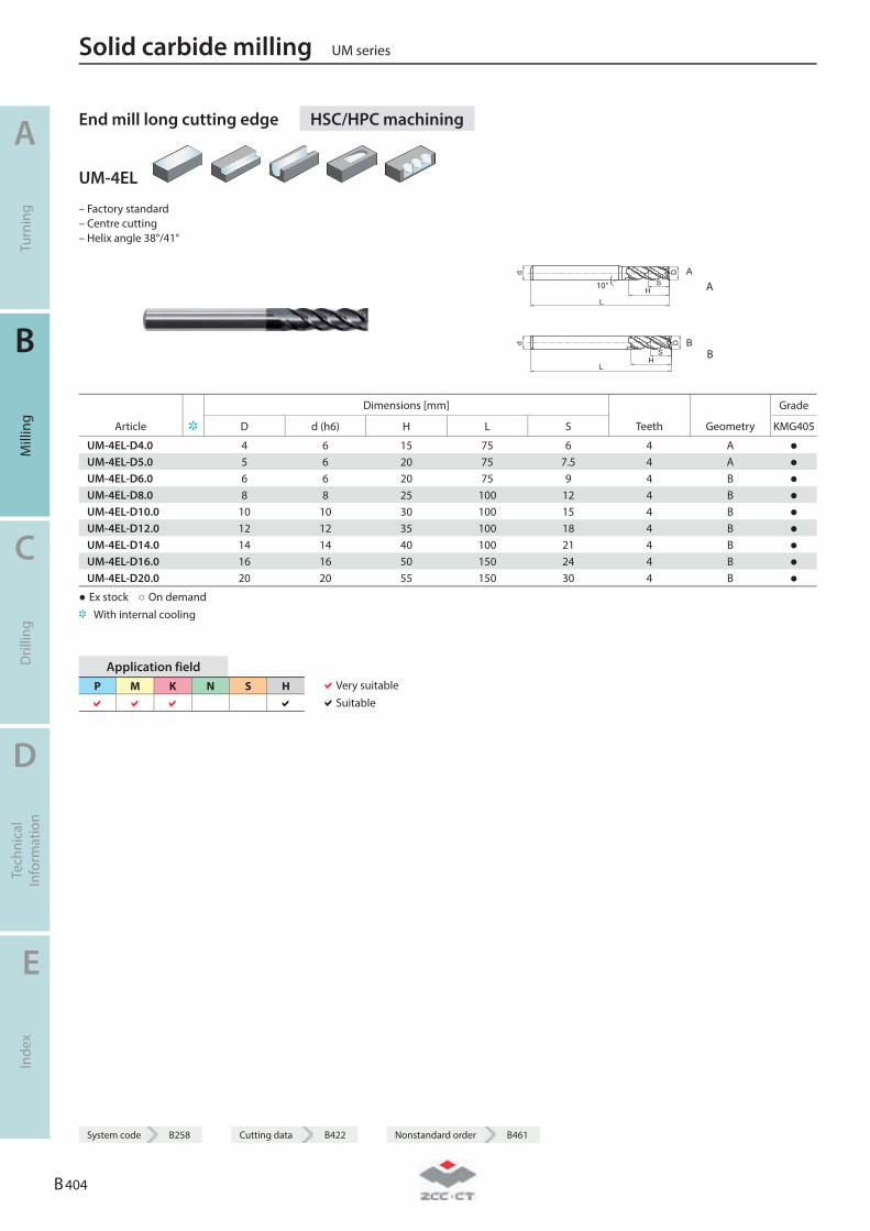
End mill long cutting edge HSC/HPC machining
UM-4EL
– Factory standard – Centre cutting – Helix angle 38°/41°
A10°
HL
S
Dd
A
B
HL
S
Dd
B
Dimensions [mm] Grade
Article D d (h6) H L S Teeth Geometry KMG405
UM-4EL-D4.0 4 6 15 75 6 4 A ● UM-4EL-D5.0 5 6 20 75 7.5 4 A ● UM-4EL-D6.0 6 6 20 75 9 4 B ● UM-4EL-D8.0 8 8 25 100 12 4 B ● UM-4EL-D10.0 10 10 30 100 15 4 B ● UM-4EL-D12.0 12 12 35 100 18 4 B ● UM-4EL-D14.0 14 14 40 100 21 4 B ● UM-4EL-D16.0 16 16 50 150 24 4 B ● UM-4EL-D20.0 20 20 55 150 30 4 B ●
● Ex stock ○ On demand With internal cooling
Application field P M K N S H
Very suitable Suitable
Solid carbide milling UM series
A
Turn
ing
B
Mill
ing
C
Dril
ling
D
Tech
nica
l In
form
atio
n
E
Inde
x
B 404
System code B258 Cutting data B422 Nonstandard order B461
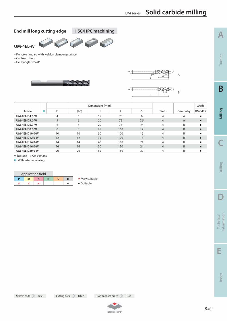
System code B258 Cutting data B422 Nonstandard order B461
End mill long cutting edge HSC/HPC machining
UM-4EL-W
– Factory standard with weldon clamping surface – Centre cutting – Helix angle 38°/41°
A10°
HL
S
Dd
A
B
HL
S
Dd
B
Dimensions [mm] Grade
Article D d (h6) H L S Teeth Geometry KMG405
UM-4EL-D4.0-W 4 6 15 75 6 4 A ● UM-4EL-D5.0-W 5 6 20 75 7.5 4 A ● UM-4EL-D6.0-W 6 6 20 75 9 4 B ● UM-4EL-D8.0-W 8 8 25 100 12 4 B ● UM-4EL-D10.0-W 10 10 30 100 15 4 B ● UM-4EL-D12.0-W 12 12 35 100 18 4 B ● UM-4EL-D14.0-W 14 14 40 100 21 4 B ● UM-4EL-D16.0-W 16 16 50 150 24 4 B ● UM-4EL-D20.0-W 20 20 55 150 30 4 B ●
● Ex stock ○ On demand With internal cooling
Application field P M K N S H
Very suitable Suitable
UM series Solid carbide milling
A
Turn
ing
B
Mill
ing
C
Dril
ling
D
Tech
nica
l In
form
atio
n
E
Inde
x
B 405
System code B258 Cutting data B422 Nonstandard order B461
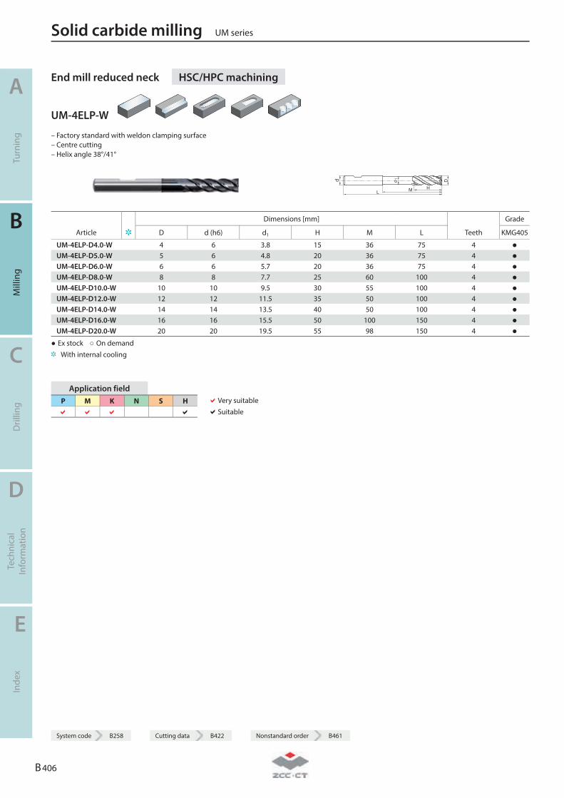
End mill reduced neck HSC/HPC machining
UM-4ELP-W
– Factory standard with weldon clamping surface – Centre cutting – Helix angle 38°/41°
d
L
d 1
HM
D
Dimensions [mm] Grade
Article D d (h6) d1 H M L Teeth KMG405
UM-4ELP-D4.0-W 4 6 3.8 15 36 75 4 ● UM-4ELP-D5.0-W 5 6 4.8 20 36 75 4 ● UM-4ELP-D6.0-W 6 6 5.7 20 36 75 4 ● UM-4ELP-D8.0-W 8 8 7.7 25 60 100 4 ● UM-4ELP-D10.0-W 10 10 9.5 30 55 100 4 ● UM-4ELP-D12.0-W 12 12 11.5 35 50 100 4 ● UM-4ELP-D14.0-W 14 14 13.5 40 50 100 4 ● UM-4ELP-D16.0-W 16 16 15.5 50 100 150 4 ● UM-4ELP-D20.0-W 20 20 19.5 55 98 150 4 ●
● Ex stock ○ On demand With internal cooling
Application field P M K N S H
Very suitable Suitable
Solid carbide milling UM series
A
Turn
ing
B
Mill
ing
C
Dril
ling
D
Tech
nica
l In
form
atio
n
E
Inde
x
B 406
System code B258 Cutting data B422 Nonstandard order B461
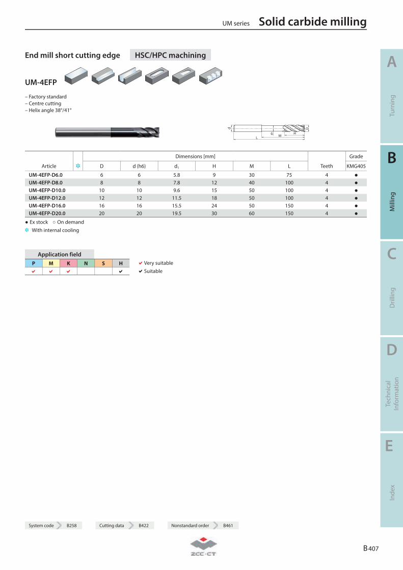
System code B258 Cutting data B422 Nonstandard order B461
End mill short cutting edge HSC/HPC machining
UM-4EFP
– Factory standard – Centre cutting – Helix angle 38°/41°
d
L
d1 HM
D
Dimensions [mm] Grade
Article D d (h6) d1 H M L Teeth KMG405
UM-4EFP-D6.0 6 6 5.8 9 30 75 4 ● UM-4EFP-D8.0 8 8 7.8 12 40 100 4 ● UM-4EFP-D10.0 10 10 9.6 15 50 100 4 ● UM-4EFP-D12.0 12 12 11.5 18 50 100 4 ● UM-4EFP-D16.0 16 16 15.5 24 50 150 4 ● UM-4EFP-D20.0 20 20 19.5 30 60 150 4 ●
● Ex stock ○ On demand With internal cooling
Application field P M K N S H
Very suitable Suitable
UM series Solid carbide milling
A
Turn
ing
B
Mill
ing
C
Dril
ling
D
Tech
nica
l In
form
atio
n
E
Inde
x
B 407
System code B258 Cutting data B422 Nonstandard order B461
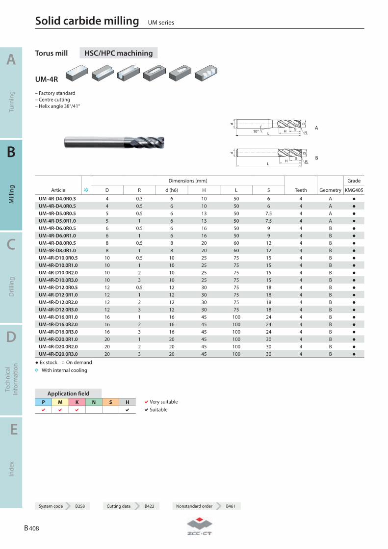
Torus mill HSC/HPC machining
UM-4R
– Factory standard – Centre cutting – Helix angle 38°/41°
10° HL
S
Dd
R A
HL
S
Dd
R B
Dimensions [mm] Grade
Article D R d (h6) H L S Teeth Geometry KMG405
UM-4R-D4.0R0.3 4 0.3 6 10 50 6 4 A ● UM-4R-D4.0R0.5 4 0.5 6 10 50 6 4 A ● UM-4R-D5.0R0.5 5 0.5 6 13 50 7.5 4 A ● UM-4R-D5.0R1.0 5 1 6 13 50 7.5 4 A ● UM-4R-D6.0R0.5 6 0.5 6 16 50 9 4 B ● UM-4R-D6.0R1.0 6 1 6 16 50 9 4 B ● UM-4R-D8.0R0.5 8 0.5 8 20 60 12 4 B ● UM-4R-D8.0R1.0 8 1 8 20 60 12 4 B ● UM-4R-D10.0R0.5 10 0.5 10 25 75 15 4 B ● UM-4R-D10.0R1.0 10 1 10 25 75 15 4 B ● UM-4R-D10.0R2.0 10 2 10 25 75 15 4 B ● UM-4R-D10.0R3.0 10 3 10 25 75 15 4 B ● UM-4R-D12.0R0.5 12 0.5 12 30 75 18 4 B ● UM-4R-D12.0R1.0 12 1 12 30 75 18 4 B ● UM-4R-D12.0R2.0 12 2 12 30 75 18 4 B ● UM-4R-D12.0R3.0 12 3 12 30 75 18 4 B ● UM-4R-D16.0R1.0 16 1 16 45 100 24 4 B ● UM-4R-D16.0R2.0 16 2 16 45 100 24 4 B ● UM-4R-D16.0R3.0 16 3 16 45 100 24 4 B ● UM-4R-D20.0R1.0 20 1 20 45 100 30 4 B ● UM-4R-D20.0R2.0 20 2 20 45 100 30 4 B ● UM-4R-D20.0R3.0 20 3 20 45 100 30 4 B ●
● Ex stock ○ On demand With internal cooling
Application field P M K N S H
Very suitable Suitable
Solid carbide milling UM series
A
Turn
ing
B
Mill
ing
C
Dril
ling
D
Tech
nica
l In
form
atio
n
E
Inde
x
B 408
System code B258 Cutting data B422 Nonstandard order B461
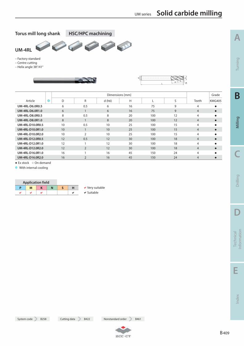
System code B258 Cutting data B422 Nonstandard order B461
Torus mill long shank HSC/HPC machining
UM-4RL
– Factory standard – Centre cutting – Helix angle 38°/41°
d
LH
D
SR
Dimensions [mm] Grade
Article D R d (h6) H L S Teeth KMG405
UM-4RL-D6.0R0.5 6 0.5 6 16 75 9 4 ● UM-4RL-D6.0R1.0 6 1 6 16 75 9 4 ● UM-4RL-D8.0R0.5 8 0.5 8 20 100 12 4 ● UM-4RL-D8.0R1.0 8 1 8 20 100 12 4 ● UM-4RL-D10.0R0.5 10 0.5 10 25 100 15 4 ● UM-4RL-D10.0R1.0 10 1 10 25 100 15 4 ● UM-4RL-D10.0R2.0 10 2 10 25 100 15 4 ● UM-4RL-D12.0R0.5 12 0.5 12 30 100 18 4 ● UM-4RL-D12.0R1.0 12 1 12 30 100 18 4 ● UM-4RL-D12.0R2.0 12 2 12 30 100 18 4 ● UM-4RL-D16.0R1.0 16 1 16 45 150 24 4 ● UM-4RL-D16.0R2.0 16 2 16 45 150 24 4 ●
● Ex stock ○ On demand With internal cooling
Application field P M K N S H
Very suitable Suitable
UM series Solid carbide milling
A
Turn
ing
B
Mill
ing
C
Dril
ling
D
Tech
nica
l In
form
atio
n
E
Inde
x
B 409
System code B258 Cutting data B422 Nonstandard order B461
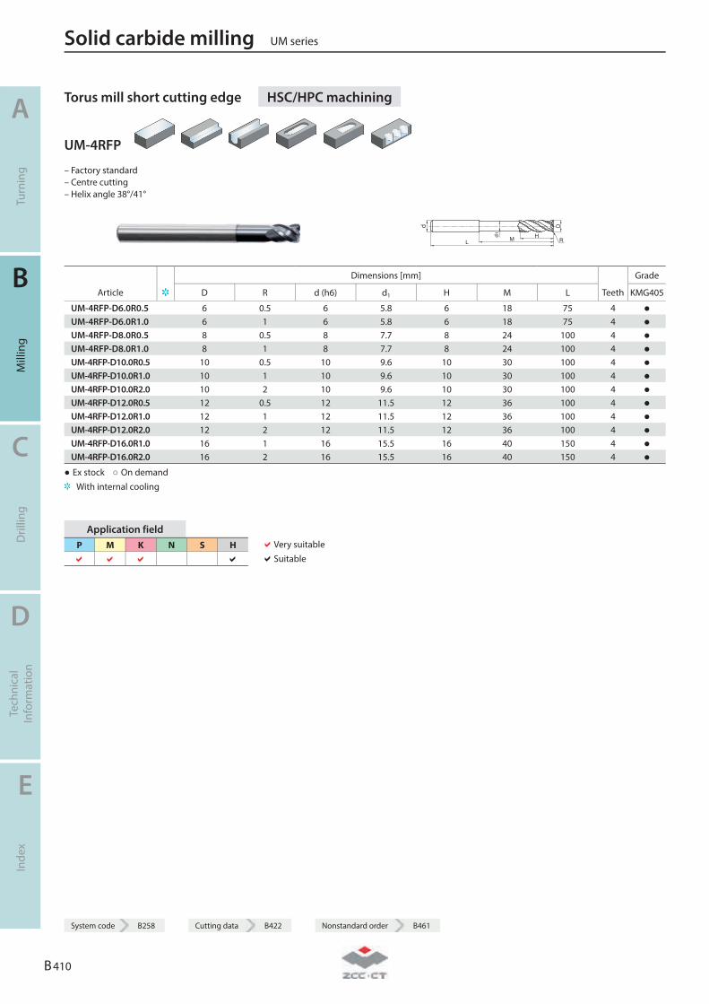
Torus mill short cutting edge HSC/HPC machining
UM-4RFP
– Factory standard – Centre cutting – Helix angle 38°/41°
d
L
d1 HM
D
R
Dimensions [mm] Grade
Article D R d (h6) d1 H M L Teeth KMG405
UM-4RFP-D6.0R0.5 6 0.5 6 5.8 6 18 75 4 ● UM-4RFP-D6.0R1.0 6 1 6 5.8 6 18 75 4 ● UM-4RFP-D8.0R0.5 8 0.5 8 7.7 8 24 100 4 ● UM-4RFP-D8.0R1.0 8 1 8 7.7 8 24 100 4 ● UM-4RFP-D10.0R0.5 10 0.5 10 9.6 10 30 100 4 ● UM-4RFP-D10.0R1.0 10 1 10 9.6 10 30 100 4 ● UM-4RFP-D10.0R2.0 10 2 10 9.6 10 30 100 4 ● UM-4RFP-D12.0R0.5 12 0.5 12 11.5 12 36 100 4 ● UM-4RFP-D12.0R1.0 12 1 12 11.5 12 36 100 4 ● UM-4RFP-D12.0R2.0 12 2 12 11.5 12 36 100 4 ● UM-4RFP-D16.0R1.0 16 1 16 15.5 16 40 150 4 ● UM-4RFP-D16.0R2.0 16 2 16 15.5 16 40 150 4 ●
● Ex stock ○ On demand With internal cooling
Application field P M K N S H
Very suitable Suitable
Solid carbide milling UM series
A
Turn
ing
B
Mill
ing
C
Dril
ling
D
Tech
nica
l In
form
atio
n
E
Inde
x
B 410
System code B258 Cutting data B422 Nonstandard order B461
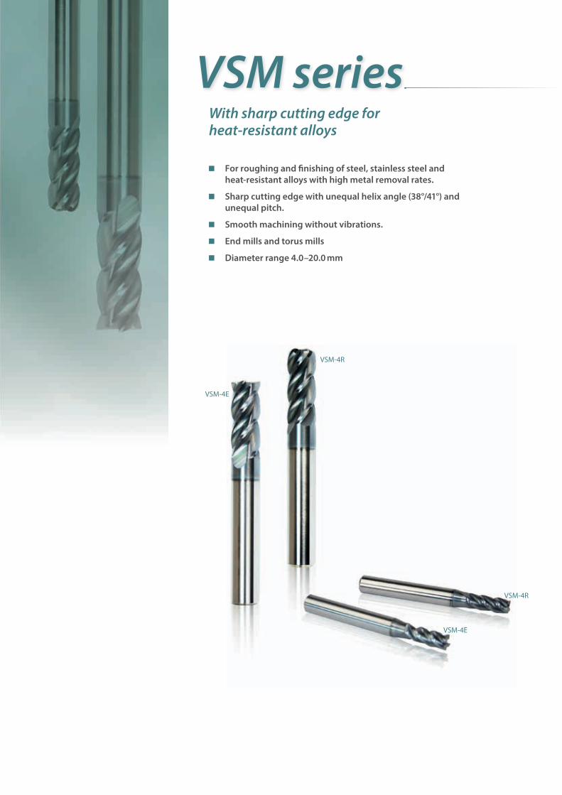
VSM series
For roughing and fi nishing of steel, stainless steel and heat-resistant alloys with high metal removal rates.
Sharp cutting edge with unequal helix angle (38°/41°) and unequal pitch.
Smooth machining without vibrations.
End mills and torus mills
Diameter range 4.0–20.0 mm
With sharp cutting edge for heat-resistant alloys
VSM-4E
VSM-4E
VSM-4R
VSM-4R
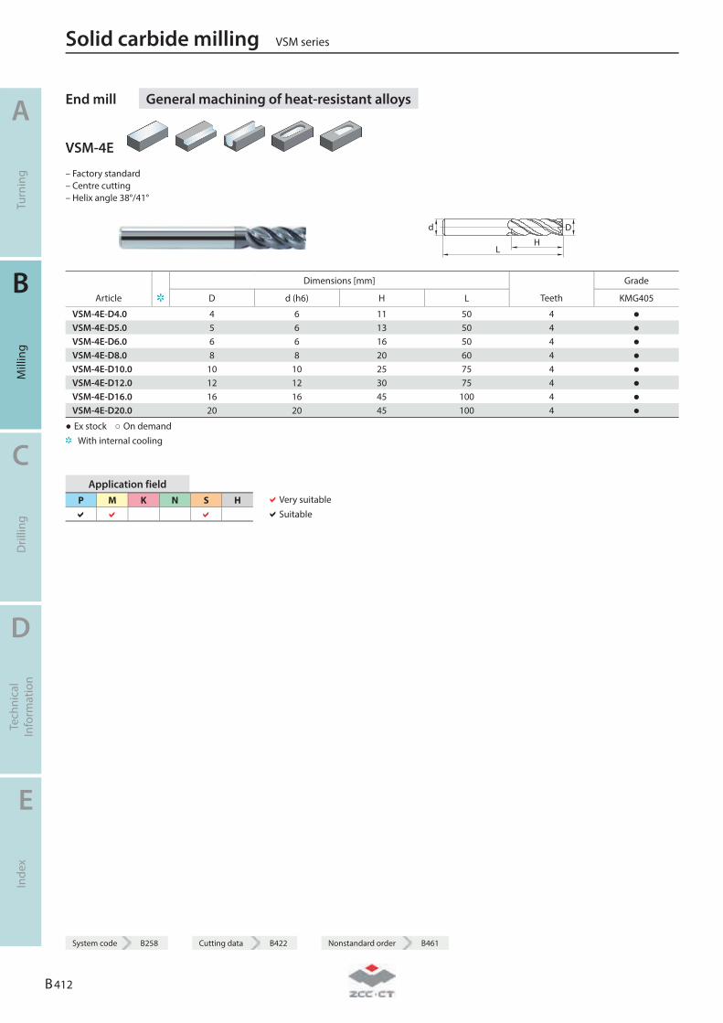
End mill General machining of heat-resistant alloys
VSM-4E
– Factory standard – Centre cutting – Helix angle 38°/41°
LH
Dd
Dimensions [mm] Grade
Article D d (h6) H L Teeth KMG405
VSM-4E-D4.0 4 6 11 50 4 ● VSM-4E-D5.0 5 6 13 50 4 ● VSM-4E-D6.0 6 6 16 50 4 ● VSM-4E-D8.0 8 8 20 60 4 ● VSM-4E-D10.0 10 10 25 75 4 ● VSM-4E-D12.0 12 12 30 75 4 ● VSM-4E-D16.0 16 16 45 100 4 ● VSM-4E-D20.0 20 20 45 100 4 ●
● Ex stock ○ On demand With internal cooling
Application field P M K N S H
Very suitable Suitable
Solid carbide milling VSM series
A
Turn
ing
B
Mill
ing
C
Dril
ling
D
Tech
nica
l In
form
atio
n
E
Inde
x
B 412
System code B258 Cutting data B422 Nonstandard order B461
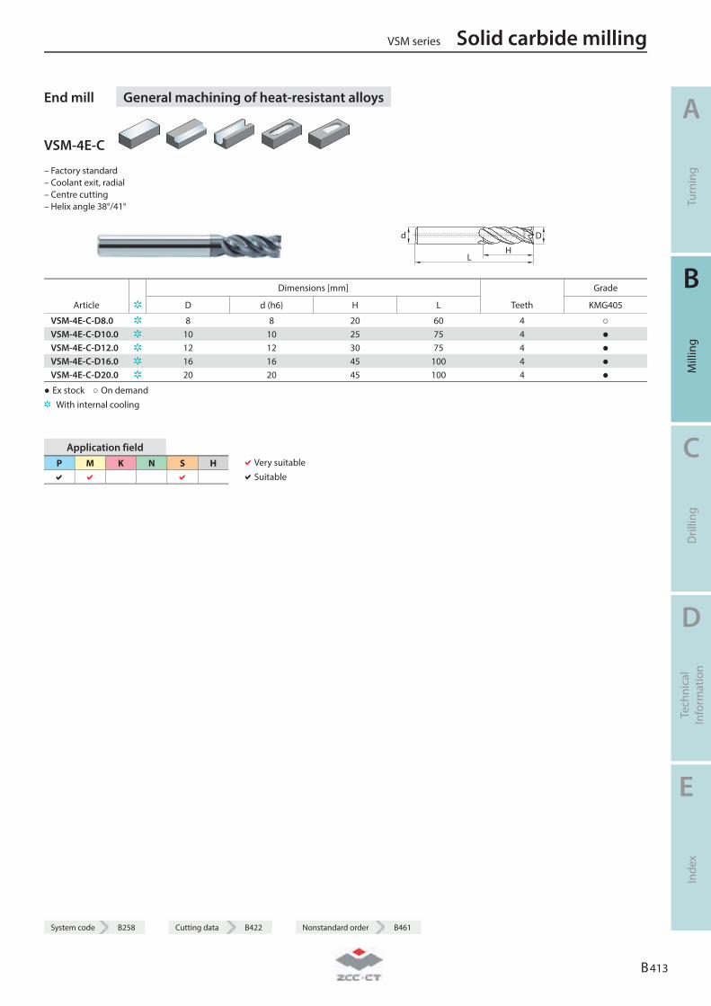
System code B258 Cutting data B422 Nonstandard order B461
End mill General machining of heat-resistant alloys
VSM-4E-C
– Factory standard – Coolant exit, radial – Centre cutting – Helix angle 38°/41°
LH
Dd
Dimensions [mm] Grade
Article D d (h6) H L Teeth KMG405
VSM-4E-C-D8.0 8 8 20 60 4 ○ VSM-4E-C-D10.0 10 10 25 75 4 ● VSM-4E-C-D12.0 12 12 30 75 4 ● VSM-4E-C-D16.0 16 16 45 100 4 ● VSM-4E-C-D20.0 20 20 45 100 4 ●
● Ex stock ○ On demand With internal cooling
Application field P M K N S H
Very suitable Suitable
VSM series Solid carbide milling
A
Turn
ing
B
Mill
ing
C
Dril
ling
D
Tech
nica
l In
form
atio
n
E
Inde
x
B 413
System code B258 Cutting data B422 Nonstandard order B461
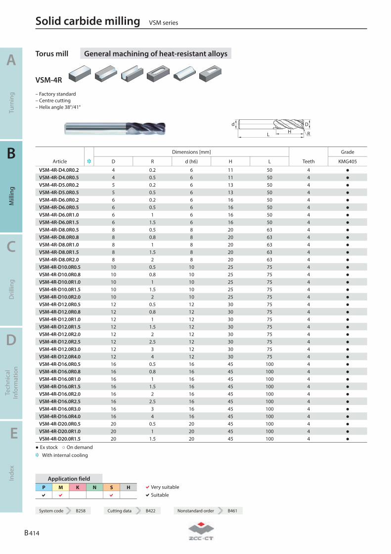
Torus mill General machining of heat-resistant alloys
VSM-4R
– Factory standard – Centre cutting – Helix angle 38°/41°
L HDd
R
Dimensions [mm] Grade
Article D R d (h6) H L Teeth KMG405
VSM-4R-D4.0R0.2 4 0.2 6 11 50 4 ● VSM-4R-D4.0R0.5 4 0.5 6 11 50 4 ● VSM-4R-D5.0R0.2 5 0.2 6 13 50 4 ● VSM-4R-D5.0R0.5 5 0.5 6 13 50 4 ● VSM-4R-D6.0R0.2 6 0.2 6 16 50 4 ● VSM-4R-D6.0R0.5 6 0.5 6 16 50 4 ● VSM-4R-D6.0R1.0 6 1 6 16 50 4 ● VSM-4R-D6.0R1.5 6 1.5 6 16 50 4 ● VSM-4R-D8.0R0.5 8 0.5 8 20 63 4 ● VSM-4R-D8.0R0.8 8 0.8 8 20 63 4 ● VSM-4R-D8.0R1.0 8 1 8 20 63 4 ● VSM-4R-D8.0R1.5 8 1.5 8 20 63 4 ● VSM-4R-D8.0R2.0 8 2 8 20 63 4 ● VSM-4R-D10.0R0.5 10 0.5 10 25 75 4 ● VSM-4R-D10.0R0.8 10 0.8 10 25 75 4 ● VSM-4R-D10.0R1.0 10 1 10 25 75 4 ● VSM-4R-D10.0R1.5 10 1.5 10 25 75 4 ● VSM-4R-D10.0R2.0 10 2 10 25 75 4 ● VSM-4R-D12.0R0.5 12 0.5 12 30 75 4 ● VSM-4R-D12.0R0.8 12 0.8 12 30 75 4 ● VSM-4R-D12.0R1.0 12 1 12 30 75 4 ● VSM-4R-D12.0R1.5 12 1.5 12 30 75 4 ● VSM-4R-D12.0R2.0 12 2 12 30 75 4 ● VSM-4R-D12.0R2.5 12 2.5 12 30 75 4 ● VSM-4R-D12.0R3.0 12 3 12 30 75 4 ● VSM-4R-D12.0R4.0 12 4 12 30 75 4 ● VSM-4R-D16.0R0.5 16 0.5 16 45 100 4 ● VSM-4R-D16.0R0.8 16 0.8 16 45 100 4 ● VSM-4R-D16.0R1.0 16 1 16 45 100 4 ● VSM-4R-D16.0R1.5 16 1.5 16 45 100 4 ● VSM-4R-D16.0R2.0 16 2 16 45 100 4 ● VSM-4R-D16.0R2.5 16 2.5 16 45 100 4 ● VSM-4R-D16.0R3.0 16 3 16 45 100 4 ● VSM-4R-D16.0R4.0 16 4 16 45 100 4 ● VSM-4R-D20.0R0.5 20 0.5 20 45 100 4 ● VSM-4R-D20.0R1.0 20 1 20 45 100 4 ● VSM-4R-D20.0R1.5 20 1.5 20 45 100 4 ●
● Ex stock ○ On demand With internal cooling
Application field P M K N S H
Very suitable Suitable
Solid carbide milling VSM series
A
Turn
ing
B
Mill
ing
C
Dril
ling
D
Tech
nica
l In
form
atio
n
E
Inde
x
B 414
System code B258 Cutting data B422 Nonstandard order B461
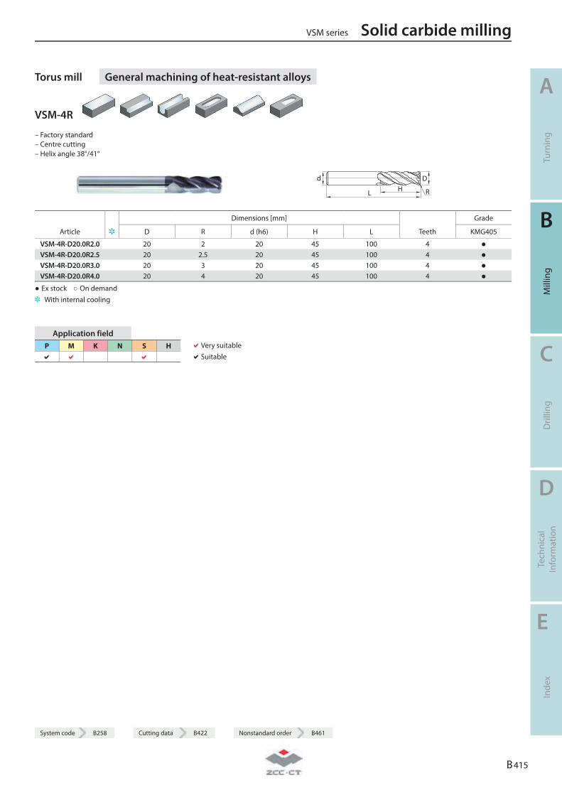
System code B258 Cutting data B422 Nonstandard order B461
Torus mill General machining of heat-resistant alloys
VSM-4R
– Factory standard – Centre cutting – Helix angle 38°/41°
L HDd
R
Dimensions [mm] Grade
Article D R d (h6) H L Teeth KMG405
VSM-4R-D20.0R2.0 20 2 20 45 100 4 ● VSM-4R-D20.0R2.5 20 2.5 20 45 100 4 ● VSM-4R-D20.0R3.0 20 3 20 45 100 4 ● VSM-4R-D20.0R4.0 20 4 20 45 100 4 ●
● Ex stock ○ On demand With internal cooling
Application field P M K N S H
Very suitable Suitable
VSM series Solid carbide milling
A
Turn
ing
B
Mill
ing
C
Dril
ling
D
Tech
nica
l In
form
atio
n
E
Inde
x
B 415
System code B258 Cutting data B422 Nonstandard order B461

Solid carbide milling VSM series
A
Turn
ing
B
Mill
ing
C
Dril
ling
D
Tech
nica
l In
form
atio
n
E
Inde
x
B 416
Notes
B 417
Deburring Cutter
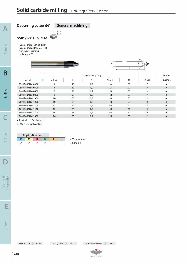
Deburring cutter 60° General machining
5501/5601R60*FM
– Type of shank DIN 6535HA – Type of shank: DIN 6535HB – Non-centre cutting – Helix angle 0°
L
Dd x
● Ex stock ○ On demand With internal cooling
Application field P M K N S H
Very suitable Suitable
Solid carbide milling Deburring cutters – FM series
A
Turn
ing
B
Mill
ing
C
Dril
ling
D
Tech
nica
l In
form
atio
n
E
Inde
x
B 418
System code B258 Cutting data B422 Nonstandard order B461
Dimensions [mm] Grade
Article d (h6) L D Shank X Teeth KMG303
5501R603FM-0300 3 48 0,2 HA 60 3 ● 5501R604FM-0400 4 48 0,2 HA 60 4 ● 5601R604FM-0600 6 55 0,2 HB 60 4 ● 5601R604FM-0800 8 58 0,5 HB 60 4 ● 5601R604FM-1000 10 65 0,5 HB 60 4 ● 5601R606FM-1000 10 65 0,7 HB 60 6 ● 5601R604FM-1200 12 75 0,5 HB 60 4 ● 5601R606FM-1200 12 75 0,7 HB 60 6 ● 5601R604FM-1600 16 85 0,7 HB 60 4 ● 5601R606FM-1600 16 85 0,7 HB 60 6 ●
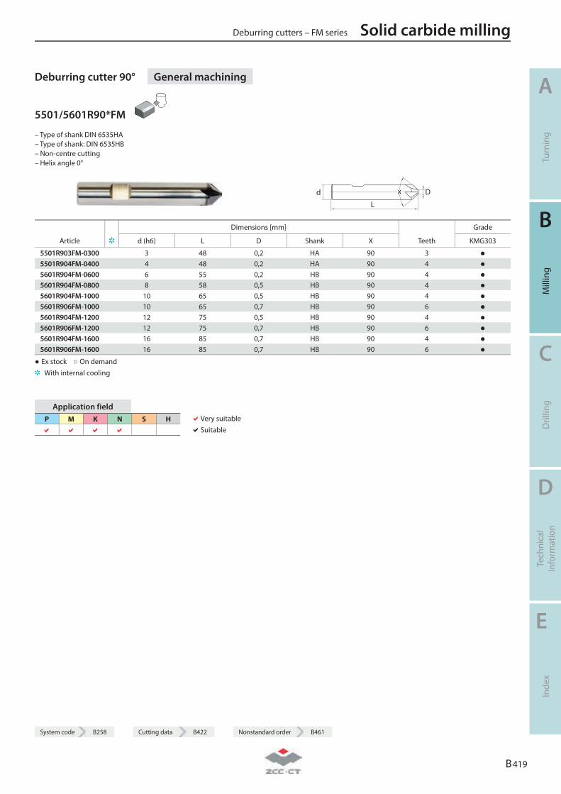
System code B258 Cutting data B422 Nonstandard order B461
Deburring cutter 90° General machining
5501/5601R90*FM
– Type of shank DIN 6535HA – Type of shank: DIN 6535HB – Non-centre cutting – Helix angle 0°
L
Dd x
● Ex stock ○ On demand With internal cooling
Application field P M K N S H
Very suitable Suitable
Deburring cutters – FM series Solid carbide milling
A
Turn
ing
B
Mill
ing
C
Dril
ling
D
Tech
nica
l In
form
atio
n
E
Inde
x
B 419
System code B258 Cutting data B422 Nonstandard order B461
Dimensions [mm] Grade
Article d (h6) L D Shank X Teeth KMG303
5501R903FM-0300 3 48 0,2 HA 90 3 ● 5501R904FM-0400 4 48 0,2 HA 90 4 ● 5601R904FM-0600 6 55 0,2 HB 90 4 ● 5601R904FM-0800 8 58 0,5 HB 90 4 ● 5601R904FM-1000 10 65 0,5 HB 90 4 ● 5601R906FM-1000 10 65 0,7 HB 90 6 ● 5601R904FM-1200 12 75 0,5 HB 90 4 ● 5601R906FM-1200 12 75 0,7 HB 90 6 ● 5601R904FM-1600 16 85 0,7 HB 90 4 ● 5601R906FM-1600 16 85 0,7 HB 90 6 ●
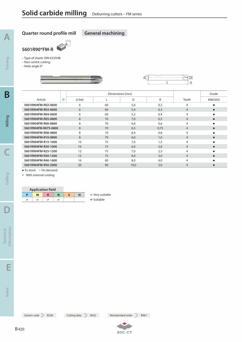
Quarter round profile mill General machining
5601R90*FM-R
– Type of shank: DIN 6535HB – Non-centre cutting – Helix angle 0°
LDdR
● Ex stock ○ On demand With internal cooling
Application field P M K N S H
Very suitable Suitable
Solid carbide milling Deburring cutters – FM series
A
Turn
ing
B
Mill
ing
C
Dril
ling
D
Tech
nica
l In
form
atio
n
E
Inde
x
B 420
System code B258 Cutting data B422 Nonstandard order B461
Dimensions [mm] Grade
Article d (h6) L D R Teeth KMG303
5601R904FM-R02-0600 6 60 5,6 0,2 4 ● 5601R904FM-R03-0600 6 60 5,4 0,3 4 ● 5601R904FM-R04-0600 6 60 5,2 0,4 4 ● 5601R904FM-R05-0800 8 70 7 ,0 0,5 4 ● 5601R904FM-R06-0800 8 70 6,8 0,6 4 ● 5601R904FM-R075-0800 8 70 6,5 0,75 4 ● 5601R904FM-R08-0800 8 70 6,4 0,8 4 ● 5601R904FM-R10-0800 8 70 6 ,0 1 ,0 4 ● 5601R904FM-R15-1000 10 75 7 ,0 1,5 4 ● 5601R904FM-R20-1000 10 75 6 ,0 2 ,0 4 ● 5601R904FM-R25-1200 12 75 7 ,0 2,5 4 ● 5601R904FM-R30-1200 12 75 6 ,0 3 ,0 4 ● 5601R904FM-R40-1600 16 80 8 ,0 4 ,0 4 ● 5601R904FM-R50-2000 20 80 10 ,0 5 ,0 4 ●
System code B258 Cutting data B422 Nonstandard order B461
Deburring cutters – FM series Solid carbide milling
A
Turn
ing
B
Mill
ing
C
Dril
ling
D
Tech
nica
l In
form
atio
n
E
Inde
x
B 421
Notes
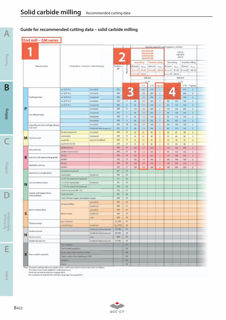
B 422
A
B
C
D
E
Turn
ing
Mill
ing
Dril
ling
Tech
nica
lIn
form
atio
nIn
dex
Guide for recommended cutting data – solid carbide milling
1 2
3 4
Recommended cutting dataSolid carbide milling
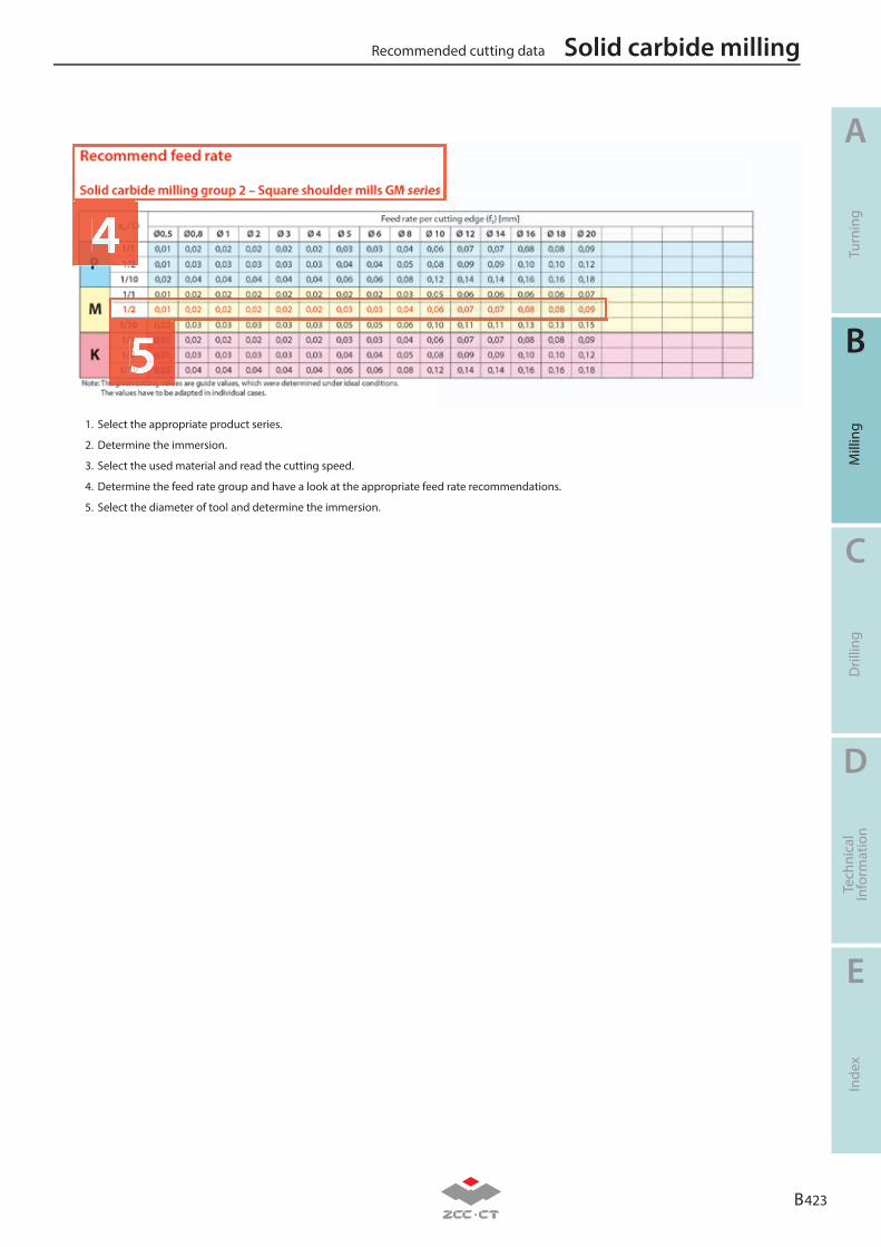
B 423
A
B
C
D
E
Turn
ing
Mill
ing
Dril
ling
Tech
nica
lIn
form
atio
nIn
dex
1. Select the appropriate product series.
2. Determine the immersion.
3. Select the used material and read the cutting speed.
4. Determine the feed rate group and have a look at the appropriate feed rate recommendations.
5. Select the diameter of tool and determine the immersion.
4
5
Recommended cutting data Solid carbide milling
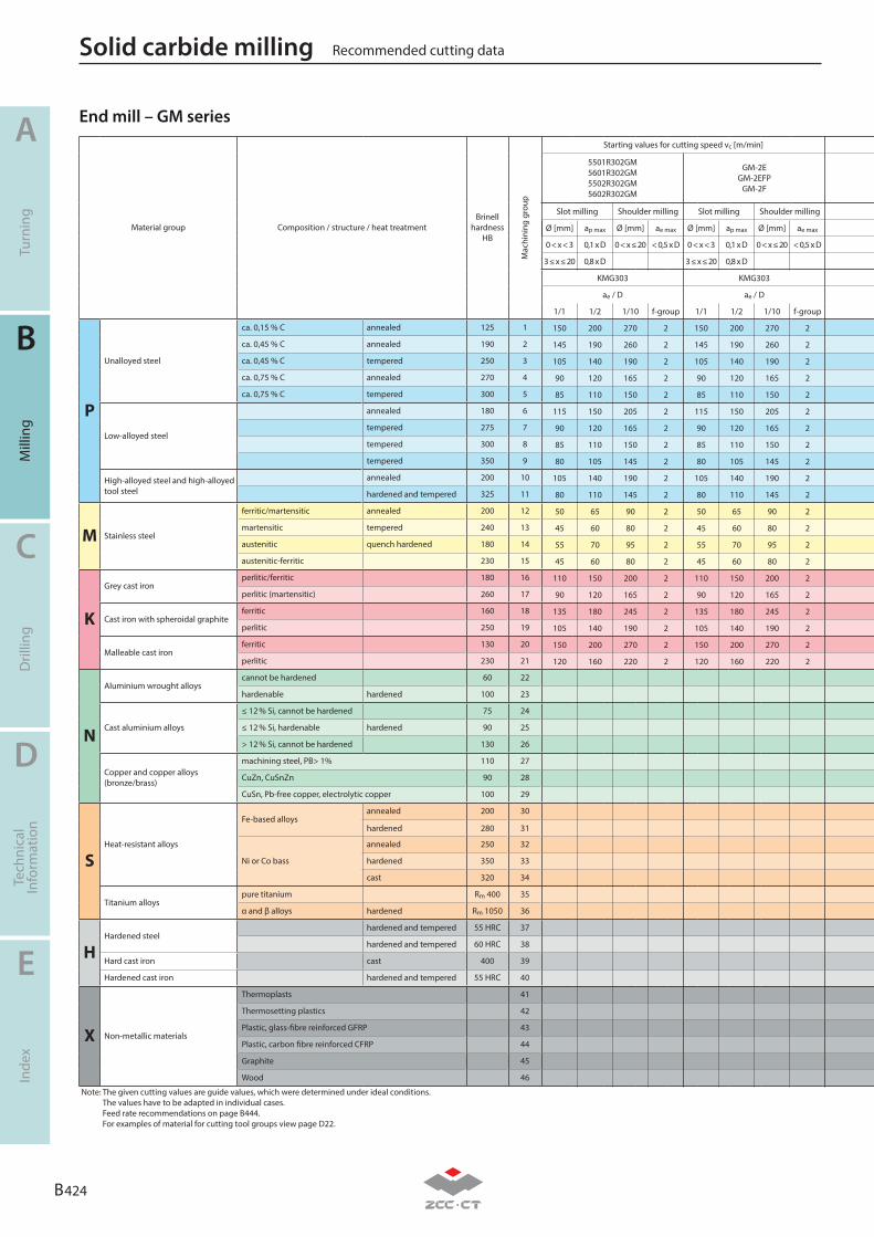
B 424
A
B
C
D
E
Turn
ing
Mill
ing
Dril
ling
Tech
nica
lIn
form
atio
nIn
dex
Recommended cutting dataSolid carbide milling
Material group Composition / structure / heat treatmentBrinell
hardness HB
Mac
hini
ng g
roup
P
Unalloyed steel
ca. 0,15 % C annealed 125 1
ca. 0,45 % C annealed 190 2
ca. 0,45 % C tempered 250 3
ca. 0,75 % C annealed 270 4
ca. 0,75 % C tempered 300 5
Low-alloyed steel
annealed 180 6
tempered 275 7
tempered 300 8
tempered 350 9
High-alloyed steel and high-alloyed tool steel
annealed 200 10
hardened and tempered 325 11
M Stainless steel
ferritic/martensitic annealed 200 12
martensitic tempered 240 13
austenitic quench hardened 180 14
austenitic-ferritic 230 15
K
Grey cast ironperlitic/ferritic 180 16
perlitic (martensitic) 260 17
Cast iron with spheroidal graphiteferritic 160 18
perlitic 250 19
Malleable cast ironferritic 130 20
perlitic 230 21
N
Aluminium wrought alloyscannot be hardened 60 22
hardenable hardened 100 23
Cast aluminium alloys
≤ 12 % Si, cannot be hardened 75 24
≤ 12 % Si, hardenable hardened 90 25
> 12 % Si, cannot be hardened 130 26
Copper and copper alloys(bronze/brass)
machining steel, PB> 1% 110 27
CuZn, CuSnZn 90 28
CuSn, Pb-free copper, electrolytic copper 100 29
SHeat-resistant alloys
Fe-based alloysannealed 200 30
hardened 280 31
Ni or Co bass
annealed 250 32
hardened 350 33
cast 320 34
Titanium alloyspure titanium Rm 400 35
α and β alloys hardened Rm 1050 36
HHardened steel
hardened and tempered 55 HRC 37
hardened and tempered 60 HRC 38
Hard cast iron cast 400 39
Hardened cast iron hardened and tempered 55 HRC 40
X Non-metallic materials
Thermoplasts 41
Thermosetting plastics 42
Plastic, glass-fibre reinforced GFRP 43
Plastic, carbon fibre reinforced CFRP 44
Graphite 45
Wood 46
Note: The given cutting values are guide values, which were determined under ideal conditions. The values have to be adapted in individual cases. Feed rate recommendations on page B444. For examples of material for cutting tool groups view page D22.
End mill – GM seriesStarting values for cutting speed vc [m/min]
5501R302GM5601R302GM5502R302GM5602R302GM
GM-2EGM-2EFP
GM-2F
Slot milling Shoulder milling Slot milling Shoulder milling
Ø [mm] ap max Ø [mm] ae max Ø [mm] ap max Ø [mm] ae max
0 < x < 3 0,1 x D 0 < x ≤ 20 < 0,5 x D 0 < x < 3 0,1 x D 0 < x ≤ 20 < 0,5 x D
3 ≤ x ≤ 20 0,8 x D 3 ≤ x ≤ 20 0,8 x D
KMG303 KMG303
ae / D ae / D
1/1 1/2 1/10 f-group 1/1 1/2 1/10 f-group
150 200 270 2 150 200 270 2
145 190 260 2 145 190 260 2
105 140 190 2 105 140 190 2
90 120 165 2 90 120 165 2
85 110 150 2 85 110 150 2
115 150 205 2 115 150 205 2
90 120 165 2 90 120 165 2
85 110 150 2 85 110 150 2
80 105 145 2 80 105 145 2
105 140 190 2 105 140 190 2
80 110 145 2 80 110 145 2
50 65 90 2 50 65 90 2
45 60 80 2 45 60 80 2
55 70 95 2 55 70 95 2
45 60 80 2 45 60 80 2
110 150 200 2 110 150 200 2
90 120 165 2 90 120 165 2
135 180 245 2 135 180 245 2
105 140 190 2 105 140 190 2
150 200 270 2 150 200 270 2
120 160 220 2 120 160 220 2
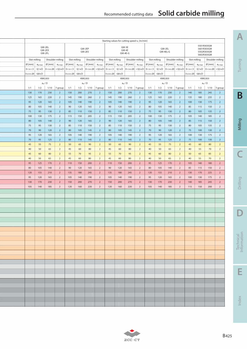
B 425
A
B
C
D
E
Turn
ing
Mill
ing
Dril
ling
Tech
nica
lIn
form
atio
nIn
dex
Recommended cutting data Solid carbide milling
Material group Composition / structure / heat treatmentBrinell
hardness HB
Mac
hini
ng g
roup
P
Unalloyed steel
ca. 0,15 % C annealed 125 1
ca. 0,45 % C annealed 190 2
ca. 0,45 % C tempered 250 3
ca. 0,75 % C annealed 270 4
ca. 0,75 % C tempered 300 5
Low-alloyed steel
annealed 180 6
tempered 275 7
tempered 300 8
tempered 350 9
High-alloyed steel and high-alloyed tool steel
annealed 200 10
hardened and tempered 325 11
M Stainless steel
ferritic/martensitic annealed 200 12
martensitic tempered 240 13
austenitic quench hardened 180 14
austenitic-ferritic 230 15
K
Grey cast ironperlitic/ferritic 180 16
perlitic (martensitic) 260 17
Cast iron with spheroidal graphiteferritic 160 18
perlitic 250 19
Malleable cast ironferritic 130 20
perlitic 230 21
N
Aluminium wrought alloyscannot be hardened 60 22
hardenable hardened 100 23
Cast aluminium alloys
≤ 12 % Si, cannot be hardened 75 24
≤ 12 % Si, hardenable hardened 90 25
> 12 % Si, cannot be hardened 130 26
Copper and copper alloys(bronze/brass)
machining steel, PB> 1% 110 27
CuZn, CuSnZn 90 28
CuSn, Pb-free copper, electrolytic copper 100 29
SHeat-resistant alloys
Fe-based alloysannealed 200 30
hardened 280 31
Ni or Co bass
annealed 250 32
hardened 350 33
cast 320 34
Titanium alloyspure titanium Rm 400 35
α and β alloys hardened Rm 1050 36
HHardened steel
hardened and tempered 55 HRC 37
hardened and tempered 60 HRC 38
Hard cast iron cast 400 39
Hardened cast iron hardened and tempered 55 HRC 40
X Non-metallic materials
Thermoplasts 41
Thermosetting plastics 42
Plastic, glass-fibre reinforced GFRP 43
Plastic, carbon fibre reinforced CFRP 44
Graphite 45
Wood 46
Note: The given cutting values are guide values, which were determined under ideal conditions. The values have to be adapted in individual cases. Feed rate recommendations on page B444. For examples of material for cutting tool groups view page D22.
Starting values for cutting speed vc [m/min]
GM-2ELGM-2EXGM-2FL
GM-2EPGM-2ES
GM-3EGM-4E
GM-4E-G
GM-2ELGM-4EL-G
5501R303GM5601R303GM5502R303GM5602R303GM
Slot milling Shoulder milling Slot milling Shoulder milling Slot milling Shoulder milling Slot milling Shoulder milling Slot milling Shoulder milling
Ø [mm] ap max Ø [mm] ae max Ø [mm] ap max Ø [mm] ae max Ø [mm] ap max Ø [mm] ae max Ø [mm] ap max Ø [mm] ae max Ø [mm] ap max Ø [mm] ae max
0 < x < 3 0,1 x D 0 < x ≤ 20 < 0,5 x D 0 < x < 3 0,1 x D 0 < x ≤ 20 < 0,5 x D 0 < x < 3 0,1 x D 0 < x ≤ 20 < 0,5 x D 0 < x < 3 0,1 x D 0 < x ≤ 20 < 0,5 x D 0 < x < 3 0,1 x D 0 < x ≤ 20 < 0,5 x D
3 ≤ x ≤ 20 0,8 x D 3 ≤ x ≤ 20 0,8 x D 3 ≤ x ≤ 20 0,8 x D 3 ≤ x ≤ 20 0,8 x D 3 ≤ x ≤ 20 0,8 x D
KMG303 KMG303 KMG303 KMG303 KMG303
ae / D ae / D ae / D ae / D ae / D
1/1 1/2 1/10 f-group 1/1 1/2 1/10 f-group 1/1 1/2 1/10 f-group 1/1 1/2 1/10 f-group 1/1 1/2 1/10 f-group
130 170 230 2 150 200 270 2 150 200 270 2 130 170 230 2 140 185 245 2
125 165 220 2 145 190 260 2 145 190 260 2 125 165 220 2 135 180 235 2
95 120 165 2 105 140 190 2 105 140 190 2 95 120 165 2 100 130 175 2
80 105 140 2 90 120 165 2 90 120 165 2 80 105 140 2 85 115 150 2
75 95 130 2 85 110 150 2 85 110 150 2 75 95 130 2 80 105 135 2
100 130 175 2 115 150 205 2 115 150 205 2 100 130 175 2 105 140 185 2
80 105 140 2 90 120 165 2 90 120 165 2 80 105 140 2 85 115 150 2
75 95 130 2 85 110 150 2 85 110 150 2 75 95 130 2 80 105 135 2
70 90 120 2 80 105 145 2 80 105 145 2 70 90 120 2 75 100 130 2
95 120 165 2 105 140 190 2 105 140 190 2 95 120 165 2 100 130 175 2
70 95 125 2 80 110 145 2 80 110 145 2 70 95 125 2 75 100 130 2
45 55 75 2 50 65 90 2 50 65 90 2 45 55 75 2 45 60 80 2
40 50 65 2 45 60 80 2 45 60 80 2 40 50 65 2 40 55 70 2
45 60 80 2 55 70 95 2 55 70 95 2 45 60 80 2 50 65 85 2
40 50 65 2 45 60 80 2 45 60 80 2 40 50 65 2 40 55 70 2
95 125 170 2 110 150 200 2 110 150 200 2 95 125 170 2 105 140 180 2
80 105 140 2 90 120 165 2 90 120 165 2 80 105 140 2 85 115 150 2
120 155 210 2 135 180 245 2 135 180 245 2 120 155 210 2 130 170 225 2
95 120 165 2 105 140 190 2 105 140 190 2 95 120 165 2 100 130 175 2
130 170 230 2 150 200 270 2 150 200 270 2 130 170 230 2 140 185 245 2
105 140 185 2 120 160 220 2 120 160 220 2 105 140 185 2 115 150 200 2

B 426
A
B
C
D
E
Turn
ing
Mill
ing
Dril
ling
Tech
nica
lIn
form
atio
nIn
dex
Recommended cutting dataSolid carbide milling
Material group Composition / structure / heat treatmentBrinell
hardness HB
Mac
hini
ng g
roup
P
Unalloyed steel
ca. 0,15 % C annealed 125 1
ca. 0,45 % C annealed 190 2
ca. 0,45 % C tempered 250 3
ca. 0,75 % C annealed 270 4
ca. 0,75 % C tempered 300 5
Low-alloyed steel
annealed 180 6
tempered 275 7
tempered 300 8
tempered 350 9
High-alloyed steel and high-alloyed tool steel
annealed 200 10
hardened and tempered 325 11
M Stainless steel
ferritic/martensitic annealed 200 12
martensitic tempered 240 13
austenitic quench hardened 180 14
austenitic-ferritic 230 15
K
Grey cast ironperlitic/ferritic 180 16
perlitic (martensitic) 260 17
Cast iron with spheroidal graphiteferritic 160 18
perlitic 250 19
Malleable cast ironferritic 130 20
perlitic 230 21
N
Aluminium wrought alloyscannot be hardened 60 22
hardenable hardened 100 23
Cast aluminium alloys
≤ 12 % Si, cannot be hardened 75 24
≤ 12 % Si, hardenable hardened 90 25
> 12 % Si, cannot be hardened 130 26
Copper and copper alloys(bronze/brass)
machining steel, PB> 1% 110 27
CuZn, CuSnZn 90 28
CuSn, Pb-free copper, electrolytic copper 100 29
SHeat-resistant alloys
Fe-based alloysannealed 200 30
hardened 280 31
Ni or Co bass
annealed 250 32
hardened 350 33
cast 320 34
Titanium alloyspure titanium Rm 400 35
α and β alloys hardened Rm 1050 36
HHardened steel
hardened and tempered 55 HRC 37
hardened and tempered 60 HRC 38
Hard cast iron cast 400 39
Hardened cast iron hardened and tempered 55 HRC 40
X Non-metallic materials
Thermoplasts 41
Thermosetting plastics 42
Plastic, glass-fibre reinforced GFRP 43
Plastic, carbon fibre reinforced CFRP 44
Graphite 45
Wood 46
Note: The given cutting values are guide values, which were determined under ideal conditions. The values have to be adapted in individual cases. Feed rate recommendations on page B444. For examples of material for cutting tool groups view page D22.
End mill – GM seriesStarting values for cutting speed vc [m/min]
5501R304GF5601R304GF5502R304GF5602R304GF
GM-4F-GGM-4EFP
Slot milling Shoulder milling Slot milling Shoulder milling
Ø [mm] ap max Ø [mm] ae max Ø [mm] ap max Ø [mm] ae max
0 < x < 3 0,1 x D 0 < x ≤ 20 < 0,5 x D 0 < x < 3 0,1 x D 0 < x ≤ 20 < 0,5 x D
3 ≤ x ≤ 20 0,8 x D 3 ≤ x ≤ 20 0,8 x D
KMG303 KMG303
ae / D ae / D
1/1 1/2 1/10 f-group 1/1 1/2 1/10 f-group
155 200 265 2 150 200 270 2
150 190 255 2 145 190 260 2
110 140 190 2 105 140 190 2
95 120 160 2 90 120 165 2
90 110 150 2 85 110 150 2
120 150 200 2 115 150 205 2
95 120 160 2 90 120 165 2
90 110 150 2 85 110 150 2
85 105 140 2 80 105 145 2
110 140 190 2 105 140 190 2
85 110 145 2 80 110 145 2
50 65 85 2 50 65 90 2
45 60 75 2 45 60 80 2
55 70 95 2 55 70 95 2
45 60 75 2 45 60 80 2
115 150 195 2 110 150 200 2
95 120 160 2 90 120 165 2
140 180 240 2 135 180 245 2
110 140 190 2 105 140 190 2
155 200 265 2 150 200 270 2
125 160 215 2 120 160 220 2
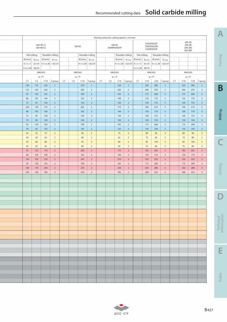
B 427
A
B
C
D
E
Turn
ing
Mill
ing
Dril
ling
Tech
nica
lIn
form
atio
nIn
dex
Recommended cutting data Solid carbide milling
Material group Composition / structure / heat treatmentBrinell
hardness HB
Mac
hini
ng g
roup
P
Unalloyed steel
ca. 0,15 % C annealed 125 1
ca. 0,45 % C annealed 190 2
ca. 0,45 % C tempered 250 3
ca. 0,75 % C annealed 270 4
ca. 0,75 % C tempered 300 5
Low-alloyed steel
annealed 180 6
tempered 275 7
tempered 300 8
tempered 350 9
High-alloyed steel and high-alloyed tool steel
annealed 200 10
hardened and tempered 325 11
M Stainless steel
ferritic/martensitic annealed 200 12
martensitic tempered 240 13
austenitic quench hardened 180 14
austenitic-ferritic 230 15
K
Grey cast ironperlitic/ferritic 180 16
perlitic (martensitic) 260 17
Cast iron with spheroidal graphiteferritic 160 18
perlitic 250 19
Malleable cast ironferritic 130 20
perlitic 230 21
N
Aluminium wrought alloyscannot be hardened 60 22
hardenable hardened 100 23
Cast aluminium alloys
≤ 12 % Si, cannot be hardened 75 24
≤ 12 % Si, hardenable hardened 90 25
> 12 % Si, cannot be hardened 130 26
Copper and copper alloys(bronze/brass)
machining steel, PB> 1% 110 27
CuZn, CuSnZn 90 28
CuSn, Pb-free copper, electrolytic copper 100 29
SHeat-resistant alloys
Fe-based alloysannealed 200 30
hardened 280 31
Ni or Co bass
annealed 250 32
hardened 350 33
cast 320 34
Titanium alloyspure titanium Rm 400 35
α and β alloys hardened Rm 1050 36
HHardened steel
hardened and tempered 55 HRC 37
hardened and tempered 60 HRC 38
Hard cast iron cast 400 39
Hardened cast iron hardened and tempered 55 HRC 40
X Non-metallic materials
Thermoplasts 41
Thermosetting plastics 42
Plastic, glass-fibre reinforced GFRP 43
Plastic, carbon fibre reinforced CFRP 44
Graphite 45
Wood 46
Note: The given cutting values are guide values, which were determined under ideal conditions. The values have to be adapted in individual cases. Feed rate recommendations on page B444. For examples of material for cutting tool groups view page D22.
Starting values for cutting speed vc [m/min]
GM-4FL-GGM-4EX-G GM-6E GM-6E
5589R45MGFR
5565R302GF5565R302GM5566R302GF
GM-2BGM-4B
GM-2BSGM-2BP
Slot milling Shoulder milling Shoulder milling Shoulder milling Slot milling Shoulder milling
Ø [mm] ap max Ø [mm] ae max Ø [mm] ae max Ø [mm] ae max Ø [mm] ap max Ø [mm] ae max
0 < x < 3 0,1 x D 0 < x ≤ 20 < 0,5 x D 0 < x ≤ 20 < 0,5 x D 0 < x ≤ 20 < 0,5 x D 0 < x < 3 0,1 x D 0 < x ≤ 20 < 0,5 x D
3 ≤ x ≤ 20 0,8 x D 3 ≤ x ≤ 20 0,8 x D
KMG303 KMG303 KMG303 KMG303 KMG303
ae / D ae / D ae / D ae / D ae / D
1/1 1/2 1/10 f-group 1/1 1/2 1/10 f-group 1/1 1/2 1/10 f-group 1/1 1/10 1/20 f-group 1/1 1/10 1/20 f-group
130 170 230 2 270 2 230 2 250 280 5 250 280 5
125 165 220 2 260 2 220 2 240 270 5 240 270 5
95 120 165 2 190 2 165 2 175 200 5 175 200 5
80 105 140 2 165 2 140 2 150 170 5 150 170 5
75 95 130 2 150 2 130 2 140 155 5 140 155 5
100 130 175 2 205 2 175 2 190 210 5 190 210 5
80 105 140 2 165 2 140 2 150 170 5 150 170 5
75 95 130 2 150 2 130 2 140 155 5 140 155 5
70 90 120 2 145 2 120 2 130 150 5 130 150 5
95 120 165 2 190 2 165 2 175 200 5 175 200 5
70 95 125 2 145 2 125 2 135 150 5 135 150 5
45 55 75 2 90 2 75 2 80 90 5 80 90 5
40 50 65 2 80 2 65 2 70 80 5 70 80 5
45 60 80 2 95 2 80 2 85 100 5 85 100 5
40 50 65 2 80 2 65 2 70 80 5 70 80 5
95 125 170 2 200 2 170 2 185 205 5 185 205 5
80 105 140 2 165 2 140 2 150 170 5 150 170 5
120 155 210 2 245 2 210 2 225 255 5 225 255 5
95 120 165 2 190 2 165 2 175 200 5 175 200 5
130 170 230 2 270 2 230 2 250 280 5 250 280 5
105 140 185 2 220 2 185 2 200 225 5 200 225 5
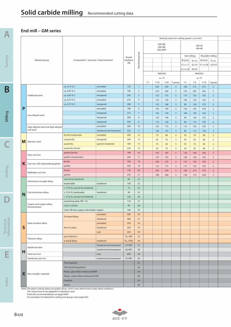
B 428
A
B
C
D
E
Turn
ing
Mill
ing
Dril
ling
Tech
nica
lIn
form
atio
nIn
dex
Recommended cutting dataSolid carbide milling
Material group Composition / structure / heat treatmentBrinell
hardness HB
Mac
hini
ng g
roup
P
Unalloyed steel
ca. 0,15 % C annealed 125 1
ca. 0,45 % C annealed 190 2
ca. 0,45 % C tempered 250 3
ca. 0,75 % C annealed 270 4
ca. 0,75 % C tempered 300 5
Low-alloyed steel
annealed 180 6
tempered 275 7
tempered 300 8
tempered 350 9
High-alloyed steel and high-alloyed tool steel
annealed 200 10
hardened and tempered 325 11
M Stainless steel
ferritic/martensitic annealed 200 12
martensitic tempered 240 13
austenitic quench hardened 180 14
austenitic-ferritic 230 15
K
Grey cast ironperlitic/ferritic 180 16
perlitic (martensitic) 260 17
Cast iron with spheroidal graphiteferritic 160 18
perlitic 250 19
Malleable cast ironferritic 130 20
perlitic 230 21
N
Aluminium wrought alloyscannot be hardened 60 22
hardenable hardened 100 23
Cast aluminium alloys
≤ 12 % Si, cannot be hardened 75 24
≤ 12 % Si, hardenable hardened 90 25
> 12 % Si, cannot be hardened 130 26
Copper and copper alloys(bronze/brass)
machining steel, PB> 1% 110 27
CuZn, CuSnZn 90 28
CuSn, Pb-free copper, electrolytic copper 100 29
SHeat-resistant alloys
Fe-based alloysannealed 200 30
hardened 280 31
Ni or Co bass
annealed 250 32
hardened 350 33
cast 320 34
Titanium alloyspure titanium Rm 400 35
α and β alloys hardened Rm 1050 36
HHardened steel
hardened and tempered 55 HRC 37
hardened and tempered 60 HRC 38
Hard cast iron cast 400 39
Hardened cast iron hardened and tempered 55 HRC 40
X Non-metallic materials
Thermoplasts 41
Thermosetting plastics 42
Plastic, glass-fibre reinforced GFRP 43
Plastic, carbon fibre reinforced CFRP 44
Graphite 45
Wood 46
Note: The given cutting values are guide values, which were determined under ideal conditions. The values have to be adapted in individual cases. Feed rate recommendations on page B444. For examples of material for cutting tool groups view page D22.
Starting values for cutting speed vc [m/min]
GM-2BLGM-4BL
GM-2BFP
GM-2RGM-4R
Slot milling Shoulder milling
Ø [mm] ap max Ø [mm] ae max
0 < x < 3 0,1 x D 0 < x ≤ 20 < 0,5 x D
3 ≤ x ≤ 20 0,8 x D
KMG303 KMG303
ae / D ae / D
1/1 1/10 1/20 f-group 1/1 1/2 1/10 f-group
220 250 5 160 215 275 2
210 240 5 155 205 265 2
155 175 5 115 155 195 2
135 150 5 100 130 165 2
125 140 5 90 120 155 2
165 190 5 120 165 210 2
135 150 5 100 130 165 2
125 140 5 90 120 155 2
115 130 5 85 115 145 2
155 175 5 115 155 195 2
120 135 5 85 115 150 2
75 80 5 55 70 90 2
65 70 5 45 65 80 2
75 85 5 55 75 95 2
65 70 5 45 65 80 2
165 185 5 120 160 205 2
135 150 5 100 130 165 2
200 225 5 145 195 250 2
155 175 5 115 155 195 2
220 250 5 160 215 275 2
180 200 5 130 175 220 2
End mill – GM series
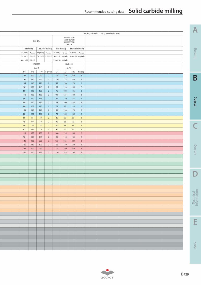
B 429
A
B
C
D
E
Turn
ing
Mill
ing
Dril
ling
Tech
nica
lIn
form
atio
nIn
dex
Recommended cutting data Solid carbide milling
Material group Composition / structure / heat treatmentBrinell
hardness HB
Mac
hini
ng g
roup
P
Unalloyed steel
ca. 0,15 % C annealed 125 1
ca. 0,45 % C annealed 190 2
ca. 0,45 % C tempered 250 3
ca. 0,75 % C annealed 270 4
ca. 0,75 % C tempered 300 5
Low-alloyed steel
annealed 180 6
tempered 275 7
tempered 300 8
tempered 350 9
High-alloyed steel and high-alloyed tool steel
annealed 200 10
hardened and tempered 325 11
M Stainless steel
ferritic/martensitic annealed 200 12
martensitic tempered 240 13
austenitic quench hardened 180 14
austenitic-ferritic 230 15
K
Grey cast ironperlitic/ferritic 180 16
perlitic (martensitic) 260 17
Cast iron with spheroidal graphiteferritic 160 18
perlitic 250 19
Malleable cast ironferritic 130 20
perlitic 230 21
N
Aluminium wrought alloyscannot be hardened 60 22
hardenable hardened 100 23
Cast aluminium alloys
≤ 12 % Si, cannot be hardened 75 24
≤ 12 % Si, hardenable hardened 90 25
> 12 % Si, cannot be hardened 130 26
Copper and copper alloys(bronze/brass)
machining steel, PB> 1% 110 27
CuZn, CuSnZn 90 28
CuSn, Pb-free copper, electrolytic copper 100 29
SHeat-resistant alloys
Fe-based alloysannealed 200 30
hardened 280 31
Ni or Co bass
annealed 250 32
hardened 350 33
cast 320 34
Titanium alloyspure titanium Rm 400 35
α and β alloys hardened Rm 1050 36
HHardened steel
hardened and tempered 55 HRC 37
hardened and tempered 60 HRC 38
Hard cast iron cast 400 39
Hardened cast iron hardened and tempered 55 HRC 40
X Non-metallic materials
Thermoplasts 41
Thermosetting plastics 42
Plastic, glass-fibre reinforced GFRP 43
Plastic, carbon fibre reinforced CFRP 44
Graphite 45
Wood 46
Note: The given cutting values are guide values, which were determined under ideal conditions. The values have to be adapted in individual cases. Feed rate recommendations on page B444. For examples of material for cutting tool groups view page D22.
Starting values for cutting speed vc [m/min]
GM-4RL
5602R303GR5602R304GR5602R305GR
GM-4W
Slot milling Shoulder milling Slot milling Shoulder milling
Ø [mm] ap max Ø [mm] ae max Ø [mm] ap max Ø [mm] ae max
0 < x < 3 0,1 x D 0 < x ≤ 20 < 0,5 x D 0 < x < 3 0,1 x D 0 < x ≤ 20 < 0,5 x D
3 ≤ x ≤ 20 0,8 x D 3 ≤ x ≤ 20 0,8 x D
KMG303 KMG303
ae / D ae / D
1/1 1/2 1/10 f-group 1/1 1/2 1/10 f-group
145 200 240 2 135 180 240 2
140 190 230 2 130 175 230 2
105 140 170 2 95 130 170 2
90 120 145 2 85 110 145 2
80 110 135 2 75 100 135 2
110 150 180 2 105 135 180 2
90 120 145 2 85 110 145 2
80 110 135 2 75 100 135 2
80 105 125 2 75 95 125 2
105 140 170 2 95 130 170 2
80 110 130 2 75 100 130 2
50 65 80 2 45 60 80 2
45 60 70 2 40 55 70 2
50 70 85 2 50 65 85 2
45 60 70 2 40 55 70 2
110 150 180 2 100 135 180 2
90 120 145 2 85 110 145 2
135 180 220 2 125 165 220 2
105 140 170 2 95 130 170 2
145 200 240 2 135 180 240 2
120 160 195 2 110 145 195 2
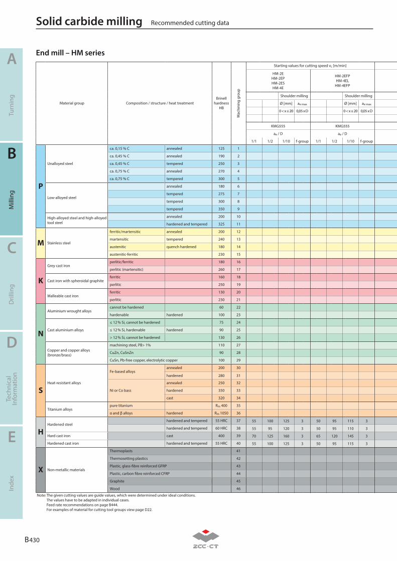
B 430
A
B
C
D
E
Turn
ing
Mill
ing
Dril
ling
Tech
nica
lIn
form
atio
nIn
dex
Recommended cutting dataSolid carbide milling
Material group Composition / structure / heat treatmentBrinell
hardness HB
Mac
hini
ng g
roup
P
Unalloyed steel
ca. 0,15 % C annealed 125 1
ca. 0,45 % C annealed 190 2
ca. 0,45 % C tempered 250 3
ca. 0,75 % C annealed 270 4
ca. 0,75 % C tempered 300 5
Low-alloyed steel
annealed 180 6
tempered 275 7
tempered 300 8
tempered 350 9
High-alloyed steel and high-alloyed tool steel
annealed 200 10
hardened and tempered 325 11
M Stainless steel
ferritic/martensitic annealed 200 12
martensitic tempered 240 13
austenitic quench hardened 180 14
austenitic-ferritic 230 15
K
Grey cast ironperlitic/ferritic 180 16
perlitic (martensitic) 260 17
Cast iron with spheroidal graphiteferritic 160 18
perlitic 250 19
Malleable cast ironferritic 130 20
perlitic 230 21
N
Aluminium wrought alloyscannot be hardened 60 22
hardenable hardened 100 23
Cast aluminium alloys
≤ 12 % Si, cannot be hardened 75 24
≤ 12 % Si, hardenable hardened 90 25
> 12 % Si, cannot be hardened 130 26
Copper and copper alloys(bronze/brass)
machining steel, PB> 1% 110 27
CuZn, CuSnZn 90 28
CuSn, Pb-free copper, electrolytic copper 100 29
SHeat-resistant alloys
Fe-based alloysannealed 200 30
hardened 280 31
Ni or Co bass
annealed 250 32
hardened 350 33
cast 320 34
Titanium alloyspure titanium Rm 400 35
α and β alloys hardened Rm 1050 36
HHardened steel
hardened and tempered 55 HRC 37
hardened and tempered 60 HRC 38
Hard cast iron cast 400 39
Hardened cast iron hardened and tempered 55 HRC 40
X Non-metallic materials
Thermoplasts 41
Thermosetting plastics 42
Plastic, glass-fibre reinforced GFRP 43
Plastic, carbon fibre reinforced CFRP 44
Graphite 45
Wood 46
Note: The given cutting values are guide values, which were determined under ideal conditions. The values have to be adapted in individual cases. Feed rate recommendations on page B444. For examples of material for cutting tool groups view page D22.
End mill – HM seriesStarting values for cutting speed vc [m/min]
HM-2EHM-2EPHM-2ESHM-4E
HM-2EFPHM-4EL
HM-4EFP
Shoulder milling Shoulder milling
Ø [mm] ae max Ø [mm] ae max
0 < x ≤ 20 0,05 x D 0 < x ≤ 20 0,05 x D
KMG555 KMG555
ae / D ae / D
1/1 1/2 1/10 f-group 1/1 1/2 1/10 f-group
55 100 125 3 50 95 115 3
55 95 120 3 50 95 110 3
70 125 160 3 65 120 145 3
55 100 125 3 50 95 115 3
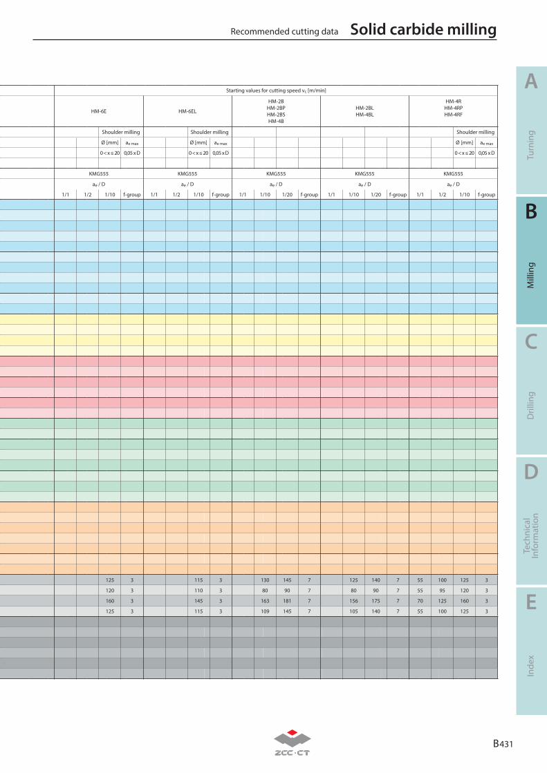
B 431
A
B
C
D
E
Turn
ing
Mill
ing
Dril
ling
Tech
nica
lIn
form
atio
nIn
dex
Recommended cutting data Solid carbide milling
Material group Composition / structure / heat treatmentBrinell
hardness HB
Mac
hini
ng g
roup
P
Unalloyed steel
ca. 0,15 % C annealed 125 1
ca. 0,45 % C annealed 190 2
ca. 0,45 % C tempered 250 3
ca. 0,75 % C annealed 270 4
ca. 0,75 % C tempered 300 5
Low-alloyed steel
annealed 180 6
tempered 275 7
tempered 300 8
tempered 350 9
High-alloyed steel and high-alloyed tool steel
annealed 200 10
hardened and tempered 325 11
M Stainless steel
ferritic/martensitic annealed 200 12
martensitic tempered 240 13
austenitic quench hardened 180 14
austenitic-ferritic 230 15
K
Grey cast ironperlitic/ferritic 180 16
perlitic (martensitic) 260 17
Cast iron with spheroidal graphiteferritic 160 18
perlitic 250 19
Malleable cast ironferritic 130 20
perlitic 230 21
N
Aluminium wrought alloyscannot be hardened 60 22
hardenable hardened 100 23
Cast aluminium alloys
≤ 12 % Si, cannot be hardened 75 24
≤ 12 % Si, hardenable hardened 90 25
> 12 % Si, cannot be hardened 130 26
Copper and copper alloys(bronze/brass)
machining steel, PB> 1% 110 27
CuZn, CuSnZn 90 28
CuSn, Pb-free copper, electrolytic copper 100 29
SHeat-resistant alloys
Fe-based alloysannealed 200 30
hardened 280 31
Ni or Co bass
annealed 250 32
hardened 350 33
cast 320 34
Titanium alloyspure titanium Rm 400 35
α and β alloys hardened Rm 1050 36
HHardened steel
hardened and tempered 55 HRC 37
hardened and tempered 60 HRC 38
Hard cast iron cast 400 39
Hardened cast iron hardened and tempered 55 HRC 40
X Non-metallic materials
Thermoplasts 41
Thermosetting plastics 42
Plastic, glass-fibre reinforced GFRP 43
Plastic, carbon fibre reinforced CFRP 44
Graphite 45
Wood 46
Note: The given cutting values are guide values, which were determined under ideal conditions. The values have to be adapted in individual cases. Feed rate recommendations on page B444. For examples of material for cutting tool groups view page D22.
Starting values for cutting speed vc [m/min]
HM-6E HM-6EL
HM-2BHM-2BPHM-2BSHM-4B
HM-2BLHM-4BL
HM-4RHM-4RPHM-4RF
Shoulder milling Shoulder milling Shoulder milling
Ø [mm] ae max Ø [mm] ae max Ø [mm] ae max
0 < x ≤ 20 0,05 x D 0 < x ≤ 20 0,05 x D 0 < x ≤ 20 0,05 x D
KMG555 KMG555 KMG555 KMG555 KMG555
ae / D ae / D ae / D ae / D ae / D
1/1 1/2 1/10 f-group 1/1 1/2 1/10 f-group 1/1 1/10 1/20 f-group 1/1 1/10 1/20 f-group 1/1 1/2 1/10 f-group
125 3 115 3 130 145 7 125 140 7 55 100 125 3
120 3 110 3 80 90 7 80 90 7 55 95 120 3
160 3 145 3 163 181 7 156 175 7 70 125 160 3
125 3 115 3 109 145 7 105 140 7 55 100 125 3
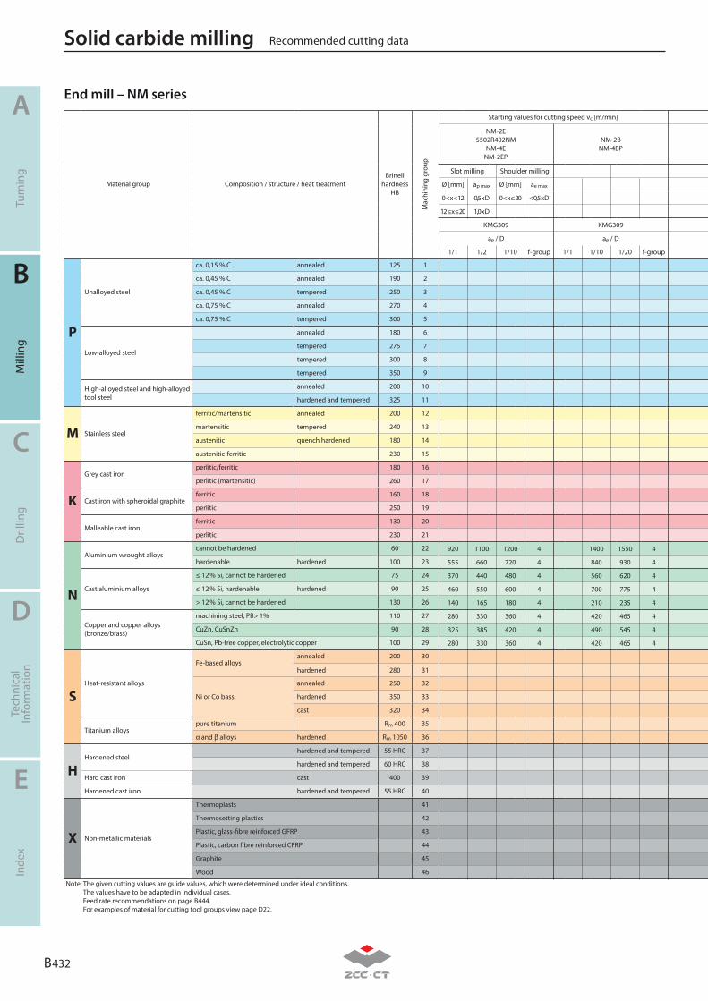
B 432
A
B
C
D
E
Turn
ing
Mill
ing
Dril
ling
Tech
nica
lIn
form
atio
nIn
dex
Recommended cutting dataSolid carbide milling
Material group Composition / structure / heat treatmentBrinell
hardness HB
Mac
hini
ng g
roup
P
Unalloyed steel
ca. 0,15 % C annealed 125 1
ca. 0,45 % C annealed 190 2
ca. 0,45 % C tempered 250 3
ca. 0,75 % C annealed 270 4
ca. 0,75 % C tempered 300 5
Low-alloyed steel
annealed 180 6
tempered 275 7
tempered 300 8
tempered 350 9
High-alloyed steel and high-alloyed tool steel
annealed 200 10
hardened and tempered 325 11
M Stainless steel
ferritic/martensitic annealed 200 12
martensitic tempered 240 13
austenitic quench hardened 180 14
austenitic-ferritic 230 15
K
Grey cast ironperlitic/ferritic 180 16
perlitic (martensitic) 260 17
Cast iron with spheroidal graphiteferritic 160 18
perlitic 250 19
Malleable cast ironferritic 130 20
perlitic 230 21
N
Aluminium wrought alloyscannot be hardened 60 22
hardenable hardened 100 23
Cast aluminium alloys
≤ 12 % Si, cannot be hardened 75 24
≤ 12 % Si, hardenable hardened 90 25
> 12 % Si, cannot be hardened 130 26
Copper and copper alloys(bronze/brass)
machining steel, PB> 1% 110 27
CuZn, CuSnZn 90 28
CuSn, Pb-free copper, electrolytic copper 100 29
SHeat-resistant alloys
Fe-based alloysannealed 200 30
hardened 280 31
Ni or Co bass
annealed 250 32
hardened 350 33
cast 320 34
Titanium alloyspure titanium Rm 400 35
α and β alloys hardened Rm 1050 36
HHardened steel
hardened and tempered 55 HRC 37
hardened and tempered 60 HRC 38
Hard cast iron cast 400 39
Hardened cast iron hardened and tempered 55 HRC 40
X Non-metallic materials
Thermoplasts 41
Thermosetting plastics 42
Plastic, glass-fibre reinforced GFRP 43
Plastic, carbon fibre reinforced CFRP 44
Graphite 45
Wood 46
Note: The given cutting values are guide values, which were determined under ideal conditions. The values have to be adapted in individual cases. Feed rate recommendations on page B444. For examples of material for cutting tool groups view page D22.
Starting values for cutting speed vc [m/min]
NM-2E5502R402NM
NM-4ENM-2EP
NM-2BNM-4BP
Slot milling Shoulder milling
Ø [mm] ap max Ø [mm] ae max
0 < x < 12 0,5 x D 0 < x ≤ 20 < 0,5 x D
12 ≤ x ≤ 20 1,0 x D
KMG309 KMG309
ae / D ae / D
1/1 1/2 1/10 f-group 1/1 1/10 1/20 f-group
920 1100 1200 4 1400 1550 4
555 660 720 4 840 930 4
370 440 480 4 560 620 4
460 550 600 4 700 775 4
140 165 180 4 210 235 4
280 330 360 4 420 465 4
325 385 420 4 490 545 4
280 330 360 4 420 465 4
End mill – NM series

B 433
A
B
C
D
E
Turn
ing
Mill
ing
Dril
ling
Tech
nica
lIn
form
atio
nIn
dex
Recommended cutting data Solid carbide milling
Material group Composition / structure / heat treatmentBrinell
hardness HB
Mac
hini
ng g
roup
P
Unalloyed steel
ca. 0,15 % C annealed 125 1
ca. 0,45 % C annealed 190 2
ca. 0,45 % C tempered 250 3
ca. 0,75 % C annealed 270 4
ca. 0,75 % C tempered 300 5
Low-alloyed steel
annealed 180 6
tempered 275 7
tempered 300 8
tempered 350 9
High-alloyed steel and high-alloyed tool steel
annealed 200 10
hardened and tempered 325 11
M Stainless steel
ferritic/martensitic annealed 200 12
martensitic tempered 240 13
austenitic quench hardened 180 14
austenitic-ferritic 230 15
K
Grey cast ironperlitic/ferritic 180 16
perlitic (martensitic) 260 17
Cast iron with spheroidal graphiteferritic 160 18
perlitic 250 19
Malleable cast ironferritic 130 20
perlitic 230 21
N
Aluminium wrought alloyscannot be hardened 60 22
hardenable hardened 100 23
Cast aluminium alloys
≤ 12 % Si, cannot be hardened 75 24
≤ 12 % Si, hardenable hardened 90 25
> 12 % Si, cannot be hardened 130 26
Copper and copper alloys(bronze/brass)
machining steel, PB> 1% 110 27
CuZn, CuSnZn 90 28
CuSn, Pb-free copper, electrolytic copper 100 29
SHeat-resistant alloys
Fe-based alloysannealed 200 30
hardened 280 31
Ni or Co bass
annealed 250 32
hardened 350 33
cast 320 34
Titanium alloyspure titanium Rm 400 35
α and β alloys hardened Rm 1050 36
HHardened steel
hardened and tempered 55 HRC 37
hardened and tempered 60 HRC 38
Hard cast iron cast 400 39
Hardened cast iron hardened and tempered 55 HRC 40
X Non-metallic materials
Thermoplasts 41
Thermosetting plastics 42
Plastic, glass-fibre reinforced GFRP 43
Plastic, carbon fibre reinforced CFRP 44
Graphite 45
Wood 46
Note: The given cutting values are guide values, which were determined under ideal conditions. The values have to be adapted in individual cases. Feed rate recommendations on page B444. For examples of material for cutting tool groups view page D22.

B 434
A
B
C
D
E
Turn
ing
Mill
ing
Dril
ling
Tech
nica
lIn
form
atio
nIn
dex
Recommended cutting dataSolid carbide milling
Material group Composition / structure / heat treatmentBrinell
hardness HB
Mac
hini
ng g
roup
P
Unalloyed steel
ca. 0,15 % C annealed 125 1
ca. 0,45 % C annealed 190 2
ca. 0,45 % C tempered 250 3
ca. 0,75 % C annealed 270 4
ca. 0,75 % C tempered 300 5
Low-alloyed steel
annealed 180 6
tempered 275 7
tempered 300 8
tempered 350 9
High-alloyed steel and high-alloyed tool steel
annealed 200 10
hardened and tempered 325 11
M Stainless steel
ferritic/martensitic annealed 200 12
martensitic tempered 240 13
austenitic quench hardened 180 14
austenitic-ferritic 230 15
K
Grey cast ironperlitic/ferritic 180 16
perlitic (martensitic) 260 17
Cast iron with spheroidal graphiteferritic 160 18
perlitic 250 19
Malleable cast ironferritic 130 20
perlitic 230 21
N
Aluminium wrought alloyscannot be hardened 60 22
hardenable hardened 100 23
Cast aluminium alloys
≤ 12 % Si, cannot be hardened 75 24
≤ 12 % Si, hardenable hardened 90 25
> 12 % Si, cannot be hardened 130 26
Copper and copper alloys(bronze/brass)
machining steel, PB> 1% 110 27
CuZn, CuSnZn 90 28
CuSn, Pb-free copper, electrolytic copper 100 29
SHeat-resistant alloys
Fe-based alloysannealed 200 30
hardened 280 31
Ni or Co bass
annealed 250 32
hardened 350 33
cast 320 34
Titanium alloyspure titanium Rm 400 35
α and β alloys hardened Rm 1050 36
HHardened steel
hardened and tempered 55 HRC 37
hardened and tempered 60 HRC 38
Hard cast iron cast 400 39
Hardened cast iron hardened and tempered 55 HRC 40
X Non-metallic materials
Thermoplasts 41
Thermosetting plastics 42
Plastic, glass-fibre reinforced GFRP 43
Plastic, carbon fibre reinforced CFRP 44
Graphite 45
Wood 46
Note: The given cutting values are guide values, which were determined under ideal conditions. The values have to be adapted in individual cases. Feed rate recommendations on page B444. For examples of material for cutting tool groups view page D22.
End mill – AL seriesStarting values for cutting speed vc [m/min]
AL-1EAL-2E
ALG-2EAL-3E
AL-2ELAL-3ELAL-3W
Slot milling Shoulder milling Slot milling Shoulder milling
Ø [mm] ap max Ø [mm] ae max Ø [mm] ap max Ø [mm] ae max
0 < x < 12 0,5 x D 0 < x ≤ 20 < 0,5 x D 0 < x < 12 0,5 x D 0 < x ≤ 20 < 0,5 x D
12 ≤ x ≤ 20 1,0 x D 12 ≤ x ≤ 20 1,0 x D
YK30F / YK40F YK30F
ae / D ae / D
1/1 1/2 1/10 f-group 1/1 1/2 1/10 f-group
920 1100 1200 4 830 990 1080 4
555 660 720 4 500 595 650 4
370 440 480 4 335 400 435 4
460 550 600 4 415 495 540 4
140 165 180 4 125 150 165 4
280 330 360 4 250 300 325 4
325 385 420 4 295 350 380 4
280 330 360 4 250 300 325 4
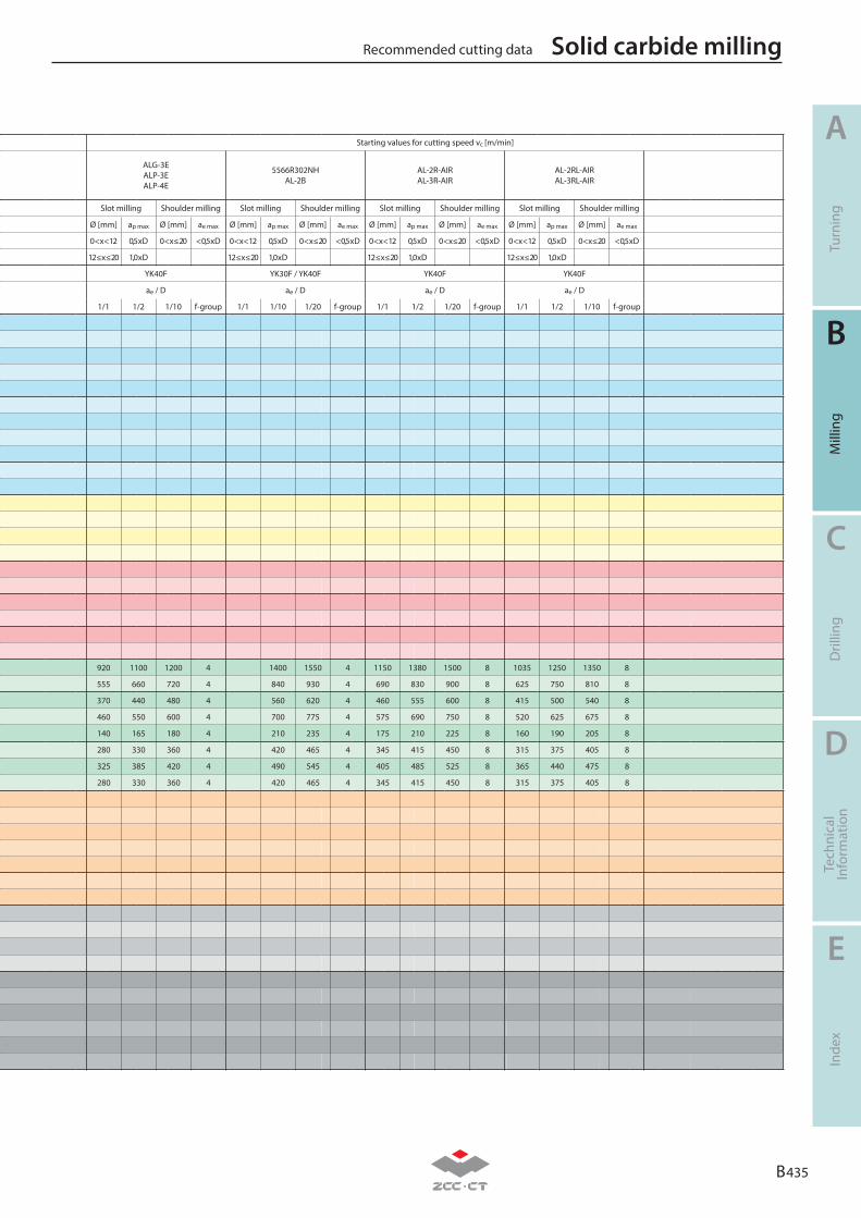
B 435
A
B
C
D
E
Turn
ing
Mill
ing
Dril
ling
Tech
nica
lIn
form
atio
nIn
dex
Recommended cutting data Solid carbide milling
Material group Composition / structure / heat treatmentBrinell
hardness HB
Mac
hini
ng g
roup
P
Unalloyed steel
ca. 0,15 % C annealed 125 1
ca. 0,45 % C annealed 190 2
ca. 0,45 % C tempered 250 3
ca. 0,75 % C annealed 270 4
ca. 0,75 % C tempered 300 5
Low-alloyed steel
annealed 180 6
tempered 275 7
tempered 300 8
tempered 350 9
High-alloyed steel and high-alloyed tool steel
annealed 200 10
hardened and tempered 325 11
M Stainless steel
ferritic/martensitic annealed 200 12
martensitic tempered 240 13
austenitic quench hardened 180 14
austenitic-ferritic 230 15
K
Grey cast ironperlitic/ferritic 180 16
perlitic (martensitic) 260 17
Cast iron with spheroidal graphiteferritic 160 18
perlitic 250 19
Malleable cast ironferritic 130 20
perlitic 230 21
N
Aluminium wrought alloyscannot be hardened 60 22
hardenable hardened 100 23
Cast aluminium alloys
≤ 12 % Si, cannot be hardened 75 24
≤ 12 % Si, hardenable hardened 90 25
> 12 % Si, cannot be hardened 130 26
Copper and copper alloys(bronze/brass)
machining steel, PB> 1% 110 27
CuZn, CuSnZn 90 28
CuSn, Pb-free copper, electrolytic copper 100 29
SHeat-resistant alloys
Fe-based alloysannealed 200 30
hardened 280 31
Ni or Co bass
annealed 250 32
hardened 350 33
cast 320 34
Titanium alloyspure titanium Rm 400 35
α and β alloys hardened Rm 1050 36
HHardened steel
hardened and tempered 55 HRC 37
hardened and tempered 60 HRC 38
Hard cast iron cast 400 39
Hardened cast iron hardened and tempered 55 HRC 40
X Non-metallic materials
Thermoplasts 41
Thermosetting plastics 42
Plastic, glass-fibre reinforced GFRP 43
Plastic, carbon fibre reinforced CFRP 44
Graphite 45
Wood 46
Note: The given cutting values are guide values, which were determined under ideal conditions. The values have to be adapted in individual cases. Feed rate recommendations on page B444. For examples of material for cutting tool groups view page D22.
Starting values for cutting speed vc [m/min]
ALG-3EALP-3EALP-4E
5566R302NHAL-2B
AL-2R-AIRAL-3R-AIR
AL-2RL-AIRAL-3RL-AIR
Slot milling Shoulder milling Slot milling Shoulder milling Slot milling Shoulder milling Slot milling Shoulder milling
Ø [mm] ap max Ø [mm] ae max Ø [mm] ap max Ø [mm] ae max Ø [mm] ap max Ø [mm] ae max Ø [mm] ap max Ø [mm] ae max
0 < x < 12 0,5 x D 0 < x ≤ 20 < 0,5 x D 0 < x < 12 0,5 x D 0 < x ≤ 20 < 0,5 x D 0 < x < 12 0,5 x D 0 < x ≤ 20 < 0,5 x D 0 < x < 12 0,5 x D 0 < x ≤ 20 < 0,5 x D
12 ≤ x ≤ 20 1,0 x D 12 ≤ x ≤ 20 1,0 x D 12 ≤ x ≤ 20 1,0 x D 12 ≤ x ≤ 20 1,0 x D
YK40F YK30F / YK40F YK40F YK40F
ae / D ae / D ae / D ae / D
1/1 1/2 1/10 f-group 1/1 1/10 1/20 f-group 1/1 1/2 1/20 f-group 1/1 1/2 1/10 f-group
920 1100 1200 4 1400 1550 4 1150 1380 1500 8 1035 1250 1350 8
555 660 720 4 840 930 4 690 830 900 8 625 750 810 8
370 440 480 4 560 620 4 460 555 600 8 415 500 540 8
460 550 600 4 700 775 4 575 690 750 8 520 625 675 8
140 165 180 4 210 235 4 175 210 225 8 160 190 205 8
280 330 360 4 420 465 4 345 415 450 8 315 375 405 8
325 385 420 4 490 545 4 405 485 525 8 365 440 475 8
280 330 360 4 420 465 4 345 415 450 8 315 375 405 8

B 436
A
B
C
D
E
Turn
ing
Mill
ing
Dril
ling
Tech
nica
lIn
form
atio
nIn
dex
Recommended cutting dataSolid carbide milling
Material group Composition / structure / heat treatmentBrinell
hardness HB
Mac
hini
ng g
roup
P
Unalloyed steel
ca. 0,15 % C annealed 125 1
ca. 0,45 % C annealed 190 2
ca. 0,45 % C tempered 250 3
ca. 0,75 % C annealed 270 4
ca. 0,75 % C tempered 300 5
Low-alloyed steel
annealed 180 6
tempered 275 7
tempered 300 8
tempered 350 9
High-alloyed steel and high-alloyed tool steel
annealed 200 10
hardened and tempered 325 11
M Stainless steel
ferritic/martensitic annealed 200 12
martensitic tempered 240 13
austenitic quench hardened 180 14
austenitic-ferritic 230 15
K
Grey cast ironperlitic/ferritic 180 16
perlitic (martensitic) 260 17
Cast iron with spheroidal graphiteferritic 160 18
perlitic 250 19
Malleable cast ironferritic 130 20
perlitic 230 21
N
Aluminium wrought alloyscannot be hardened 60 22
hardenable hardened 100 23
Cast aluminium alloys
≤ 12 % Si, cannot be hardened 75 24
≤ 12 % Si, hardenable hardened 90 25
> 12 % Si, cannot be hardened 130 26
Copper and copper alloys(bronze/brass)
machining steel, PB> 1% 110 27
CuZn, CuSnZn 90 28
CuSn, Pb-free copper, electrolytic copper 100 29
SHeat-resistant alloys
Fe-based alloysannealed 200 30
hardened 280 31
Ni or Co bass
annealed 250 32
hardened 350 33
cast 320 34
Titanium alloyspure titanium Rm 400 35
α and β alloys hardened Rm 1050 36
HHardened steel
hardened and tempered 55 HRC 37
hardened and tempered 60 HRC 38
Hard cast iron cast 400 39
Hardened cast iron hardened and tempered 55 HRC 40
X Non-metallic materials
Thermoplasts 41
Thermosetting plastics 42
Plastic, glass-fibre reinforced GFRP 43
Plastic, carbon fibre reinforced CFRP 44
Graphite 45
Wood 46
Note: The given cutting values are guide values, which were determined under ideal conditions. The values have to be adapted in individual cases. Feed rate recommendations on page B240. For examples of material for cutting tool groups view page D22.
End mill – PM seriesStarting values for cutting speed vc [m/min]
PM-2EPM-4E
PM-4E-G
PM-4ELPM-4EL-GPM-4EX-G
Slot milling Shoulder milling Slot milling Shoulder milling
Ø [mm] ap max Ø [mm] ae max Ø [mm] ap max Ø [mm] ae max
0 < x < 3 0,1 5x D 0 < x ≤ 20 0.15 x D 0 < x < 3 0,1 5x D 0 < x ≤ 20 0.15 x D
3 ≤ x < 6 0,3 x D 3 ≤ x < 6 0,3 x D
6 ≤ x ≤ 20 0,5 x D 6 ≤ x ≤ 20 0,5 x D
KMG405 KMG405
ae / D ae / D
1/1 1/2 1/10 f-group 1/1 1/2 1/10 f-group
165 220 300 1 140 190 255 1
160 210 285 1 135 185 245 1
120 155 210 1 100 135 180 1
100 135 180 1 85 115 155 1
95 125 165 1 80 105 145 1
125 165 225 1 110 145 195 1
100 135 180 1 85 115 155 1
95 125 165 1 80 105 145 1
90 115 160 1 75 100 135 1
120 155 210 1 100 135 180 1
90 120 160 1 75 105 140 1
55 75 100 1 45 65 85 1
50 65 85 1 40 55 75 1
60 75 105 1 50 65 90 1
50 65 85 1 40 55 75 1
125 165 220 1 105 140 190 1
100 135 180 1 85 115 155 1
150 200 270 1 130 175 230 1
120 155 210 1 100 135 180 1
165 220 300 1 145 190 255 1
135 180 240 1 115 155 205 1
80 105 140 1 65 90 120 1
105 140 185 1 85 120 160 1
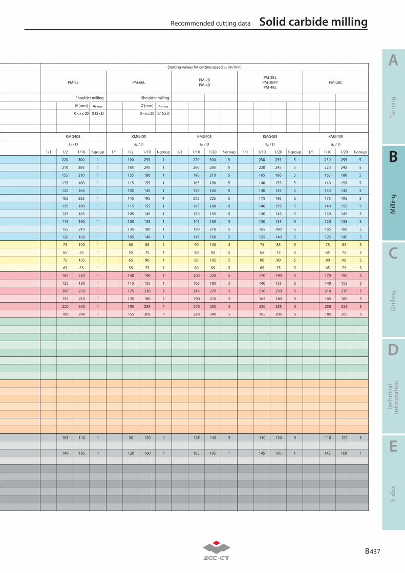
B 437
A
B
C
D
E
Turn
ing
Mill
ing
Dril
ling
Tech
nica
lIn
form
atio
nIn
dex
Recommended cutting data Solid carbide milling
Material group Composition / structure / heat treatmentBrinell
hardness HB
Mac
hini
ng g
roup
P
Unalloyed steel
ca. 0,15 % C annealed 125 1
ca. 0,45 % C annealed 190 2
ca. 0,45 % C tempered 250 3
ca. 0,75 % C annealed 270 4
ca. 0,75 % C tempered 300 5
Low-alloyed steel
annealed 180 6
tempered 275 7
tempered 300 8
tempered 350 9
High-alloyed steel and high-alloyed tool steel
annealed 200 10
hardened and tempered 325 11
M Stainless steel
ferritic/martensitic annealed 200 12
martensitic tempered 240 13
austenitic quench hardened 180 14
austenitic-ferritic 230 15
K
Grey cast ironperlitic/ferritic 180 16
perlitic (martensitic) 260 17
Cast iron with spheroidal graphiteferritic 160 18
perlitic 250 19
Malleable cast ironferritic 130 20
perlitic 230 21
N
Aluminium wrought alloyscannot be hardened 60 22
hardenable hardened 100 23
Cast aluminium alloys
≤ 12 % Si, cannot be hardened 75 24
≤ 12 % Si, hardenable hardened 90 25
> 12 % Si, cannot be hardened 130 26
Copper and copper alloys(bronze/brass)
machining steel, PB> 1% 110 27
CuZn, CuSnZn 90 28
CuSn, Pb-free copper, electrolytic copper 100 29
SHeat-resistant alloys
Fe-based alloysannealed 200 30
hardened 280 31
Ni or Co bass
annealed 250 32
hardened 350 33
cast 320 34
Titanium alloyspure titanium Rm 400 35
α and β alloys hardened Rm 1050 36
HHardened steel
hardened and tempered 55 HRC 37
hardened and tempered 60 HRC 38
Hard cast iron cast 400 39
Hardened cast iron hardened and tempered 55 HRC 40
X Non-metallic materials
Thermoplasts 41
Thermosetting plastics 42
Plastic, glass-fibre reinforced GFRP 43
Plastic, carbon fibre reinforced CFRP 44
Graphite 45
Wood 46
Note: The given cutting values are guide values, which were determined under ideal conditions. The values have to be adapted in individual cases. Feed rate recommendations on page B240. For examples of material for cutting tool groups view page D22.
Starting values for cutting speed vc [m/min]
PM-6E PM-6EL PM-2BPM-4B
PM-2BLPM-2BFPPM-4BL
PM-2BC
Shoulder milling Shoulder milling
Ø [mm] ae max Ø [mm] ae max
0 < x ≤ 20 0.15 x D 0 < x ≤ 20 0.15 x D
KMG405 KMG405 KMG405 KMG405 KMG405
ae / D ae / D ae / D ae / D ae / D
1/1 1/2 1/10 f-group 1/1 1/2 1/10 f-group 1/1 1/10 1/20 f-group 1/1 1/10 1/20 f-group 1/1 1/10 1/20 f-group
220 300 1 190 255 1 270 300 5 230 255 5 230 255 5
210 285 1 185 245 1 260 285 5 220 245 5 220 245 5
155 210 1 135 180 1 190 210 5 165 180 5 165 180 5
135 180 1 115 155 1 165 180 5 140 155 5 140 155 5
125 165 1 105 145 1 150 165 5 130 145 5 130 145 5
165 225 1 145 195 1 205 225 5 175 195 5 175 195 5
135 180 1 115 155 1 165 180 5 140 155 5 140 155 5
125 165 1 105 145 1 150 165 5 130 145 5 130 145 5
115 160 1 100 135 1 145 160 5 120 135 5 120 135 5
155 210 1 135 180 1 190 210 5 165 180 5 165 180 5
120 160 1 105 140 1 145 160 5 125 140 5 125 140 5
75 100 1 65 85 1 90 100 5 75 85 5 75 85 5
65 85 1 55 75 1 80 85 5 65 75 5 65 75 5
75 105 1 65 90 1 95 105 5 80 90 5 80 90 5
65 85 1 55 75 1 80 85 5 65 75 5 65 75 5
165 220 1 140 190 1 200 220 5 170 190 5 170 190 5
135 180 1 115 155 1 165 180 5 140 155 5 140 155 5
200 270 1 175 230 1 245 270 5 210 230 5 210 230 5
155 210 1 135 180 1 190 210 5 165 180 5 165 180 5
220 300 1 190 255 1 270 300 5 230 255 5 230 255 5
180 240 1 155 205 1 220 240 5 185 205 5 185 205 5
105 140 1 90 120 1 125 140 5 110 120 5 110 120 5
140 185 1 120 160 1 165 185 1 145 160 1 145 160 1

B 438
A
B
C
D
E
Turn
ing
Mill
ing
Dril
ling
Tech
nica
lIn
form
atio
nIn
dex
Recommended cutting dataSolid carbide milling
Material group Composition / structure / heat treatmentBrinell
hardness HB
Mac
hini
ng g
roup
P
Unalloyed steel
ca. 0,15 % C annealed 125 1
ca. 0,45 % C annealed 190 2
ca. 0,45 % C tempered 250 3
ca. 0,75 % C annealed 270 4
ca. 0,75 % C tempered 300 5
Low-alloyed steel
annealed 180 6
tempered 275 7
tempered 300 8
tempered 350 9
High-alloyed steel and high-alloyed tool steel
annealed 200 10
hardened and tempered 325 11
M Stainless steel
ferritic/martensitic annealed 200 12
martensitic tempered 240 13
austenitic quench hardened 180 14
austenitic-ferritic 230 15
K
Grey cast ironperlitic/ferritic 180 16
perlitic (martensitic) 260 17
Cast iron with spheroidal graphiteferritic 160 18
perlitic 250 19
Malleable cast ironferritic 130 20
perlitic 230 21
N
Aluminium wrought alloyscannot be hardened 60 22
hardenable hardened 100 23
Cast aluminium alloys
≤ 12 % Si, cannot be hardened 75 24
≤ 12 % Si, hardenable hardened 90 25
> 12 % Si, cannot be hardened 130 26
Copper and copper alloys(bronze/brass)
machining steel, PB> 1% 110 27
CuZn, CuSnZn 90 28
CuSn, Pb-free copper, electrolytic copper 100 29
SHeat-resistant alloys
Fe-based alloysannealed 200 30
hardened 280 31
Ni or Co bass
annealed 250 32
hardened 350 33
cast 320 34
Titanium alloyspure titanium Rm 400 35
α and β alloys hardened Rm 1050 36
HHardened steel
hardened and tempered 55 HRC 37
hardened and tempered 60 HRC 38
Hard cast iron cast 400 39
Hardened cast iron hardened and tempered 55 HRC 40
X Non-metallic materials
Thermoplasts 41
Thermosetting plastics 42
Plastic, glass-fibre reinforced GFRP 43
Plastic, carbon fibre reinforced CFRP 44
Graphite 45
Wood 46
Note: The given cutting values are guide values, which were determined under ideal conditions. The values have to be adapted in individual cases. Feed rate recommendations on page B240. For examples of material for cutting tool groups view page D22.
End mill – PM seriesStarting values for cutting speed vc [m/min]
PM-2RPM-4R PM-4RL
Slot milling Shoulder milling Slot milling Shoulder milling
Ø [mm] ap max Ø [mm] ae max Ø [mm] ap max Ø [mm] ae max
0 < x < 3 0,1 5x D 0 < x ≤ 20 0.15 x D 0 < x < 3 0,1 5x D 0 < x ≤ 20 0.15 x D
3 ≤ x < 6 0,3 x D 3 ≤ x < 6 0,3 x D
6 ≤ x ≤ 20 0,5 x D 6 ≤ x ≤ 20 0,5 x D
KMG405 KMG405
ae / D ae / D
1/1 1/2 1/10 f-group 1/1 1/2 1/10 f-group
165 220 300 1 150 200 265 1
160 210 285 1 145 190 255 1
120 155 210 1 105 140 190 1
100 135 180 1 90 120 160 1
95 125 165 1 85 110 150 1
125 165 225 1 115 150 200 1
100 135 180 1 90 120 160 1
95 125 165 1 85 110 150 1
90 115 160 1 80 105 140 1
120 155 210 1 105 140 190 1
90 120 160 1 80 110 145 1
55 75 100 1 50 65 85 1
50 65 85 1 45 60 75 1
60 75 105 1 55 70 95 1
50 65 85 1 45 60 75 1
125 165 220 1 110 150 195 1
100 135 180 1 90 120 160 1
150 200 270 1 135 180 240 1
120 155 210 1 105 140 190 1
165 220 300 1 150 200 265 1
135 180 240 1 120 160 215 1
85 110 145 1 70 95 125 1
115 145 190 1 95 125 165 1
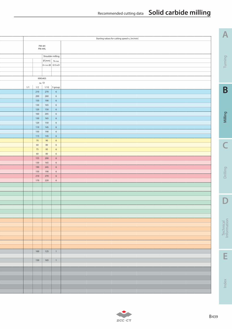
B 439
A
B
C
D
E
Turn
ing
Mill
ing
Dril
ling
Tech
nica
lIn
form
atio
nIn
dex
Recommended cutting data Solid carbide milling
Material group Composition / structure / heat treatmentBrinell
hardness HB
Mac
hini
ng g
roup
P
Unalloyed steel
ca. 0,15 % C annealed 125 1
ca. 0,45 % C annealed 190 2
ca. 0,45 % C tempered 250 3
ca. 0,75 % C annealed 270 4
ca. 0,75 % C tempered 300 5
Low-alloyed steel
annealed 180 6
tempered 275 7
tempered 300 8
tempered 350 9
High-alloyed steel and high-alloyed tool steel
annealed 200 10
hardened and tempered 325 11
M Stainless steel
ferritic/martensitic annealed 200 12
martensitic tempered 240 13
austenitic quench hardened 180 14
austenitic-ferritic 230 15
K
Grey cast ironperlitic/ferritic 180 16
perlitic (martensitic) 260 17
Cast iron with spheroidal graphiteferritic 160 18
perlitic 250 19
Malleable cast ironferritic 130 20
perlitic 230 21
N
Aluminium wrought alloyscannot be hardened 60 22
hardenable hardened 100 23
Cast aluminium alloys
≤ 12 % Si, cannot be hardened 75 24
≤ 12 % Si, hardenable hardened 90 25
> 12 % Si, cannot be hardened 130 26
Copper and copper alloys(bronze/brass)
machining steel, PB> 1% 110 27
CuZn, CuSnZn 90 28
CuSn, Pb-free copper, electrolytic copper 100 29
SHeat-resistant alloys
Fe-based alloysannealed 200 30
hardened 280 31
Ni or Co bass
annealed 250 32
hardened 350 33
cast 320 34
Titanium alloyspure titanium Rm 400 35
α and β alloys hardened Rm 1050 36
HHardened steel
hardened and tempered 55 HRC 37
hardened and tempered 60 HRC 38
Hard cast iron cast 400 39
Hardened cast iron hardened and tempered 55 HRC 40
X Non-metallic materials
Thermoplasts 41
Thermosetting plastics 42
Plastic, glass-fibre reinforced GFRP 43
Plastic, carbon fibre reinforced CFRP 44
Graphite 45
Wood 46
Note: The given cutting values are guide values, which were determined under ideal conditions. The values have to be adapted in individual cases. Feed rate recommendations on page B240. For examples of material for cutting tool groups view page D22.
Starting values for cutting speed vc [m/min]
PM-4HPM-4HL
Shoulder milling
Ø [mm] ae max
0 < x ≤ 20 0.15 x D
KMG405
ae / D
1/1 1/2 1/10 f-group
210 270 6
200 260 6
150 190 6
130 165 6
120 150 6
160 205 6
130 165 6
120 150 6
110 145 6
150 190 6
115 145 6
70 90 6
60 80 6
75 95 6
60 80 6
155 200 6
130 165 6
190 245 6
150 190 6
210 270 6
170 220 6
100 125 1
130 165 1
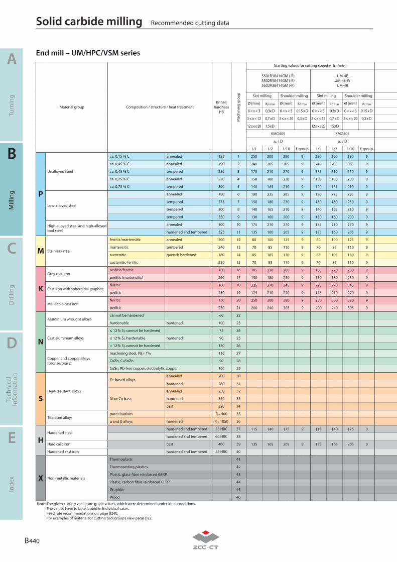
B 440
A
B
C
D
E
Turn
ing
Mill
ing
Dril
ling
Tech
nica
lIn
form
atio
nIn
dex
Recommended cutting dataSolid carbide milling
Material group Composition / structure / heat treatmentBrinell
hardness HB
Mac
hini
ng g
roup
P
Unalloyed steel
ca. 0,15 % C annealed 125 1
ca. 0,45 % C annealed 190 2
ca. 0,45 % C tempered 250 3
ca. 0,75 % C annealed 270 4
ca. 0,75 % C tempered 300 5
Low-alloyed steel
annealed 180 6
tempered 275 7
tempered 300 8
tempered 350 9
High-alloyed steel and high-alloyed tool steel
annealed 200 10
hardened and tempered 325 11
M Stainless steel
ferritic/martensitic annealed 200 12
martensitic tempered 240 13
austenitic quench hardened 180 14
austenitic-ferritic 230 15
K
Grey cast ironperlitic/ferritic 180 16
perlitic (martensitic) 260 17
Cast iron with spheroidal graphiteferritic 160 18
perlitic 250 19
Malleable cast ironferritic 130 20
perlitic 230 21
N
Aluminium wrought alloyscannot be hardened 60 22
hardenable hardened 100 23
Cast aluminium alloys
≤ 12 % Si, cannot be hardened 75 24
≤ 12 % Si, hardenable hardened 90 25
> 12 % Si, cannot be hardened 130 26
Copper and copper alloys(bronze/brass)
machining steel, PB> 1% 110 27
CuZn, CuSnZn 90 28
CuSn, Pb-free copper, electrolytic copper 100 29
SHeat-resistant alloys
Fe-based alloysannealed 200 30
hardened 280 31
Ni or Co bass
annealed 250 32
hardened 350 33
cast 320 34
Titanium alloyspure titanium Rm 400 35
α and β alloys hardened Rm 1050 36
HHardened steel
hardened and tempered 55 HRC 37
hardened and tempered 60 HRC 38
Hard cast iron cast 400 39
Hardened cast iron hardened and tempered 55 HRC 40
X Non-metallic materials
Thermoplasts 41
Thermosetting plastics 42
Plastic, glass-fibre reinforced GFRP 43
Plastic, carbon fibre reinforced CFRP 44
Graphite 45
Wood 46
Note: The given cutting values are guide values, which were determined under ideal conditions. The values have to be adapted in individual cases. Feed rate recommendations on page B240. For examples of material for cutting tool groups view page D22.
End mill – UM/HPC/VSM seriesStarting values for cutting speed vc [m/min]
5501R38414GM (-R)5502R38414GM (-R)5602R38414GM (-R)
UM-4EUM-4E-W
UM-4R
Slot milling Shoulder milling Slot milling Shoulder milling
Ø [mm] ap max Ø [mm] ae max Ø [mm] ap max Ø [mm] ae max
0 < x < 3 0,3x D 0 < x < 3 0.15 x D 0 < x < 3 0,3x D 0 < x < 3 0.15 x D
3 ≤ x < 12 0,7 x D 3 ≤ x < 20 0,3 x D 3 ≤ x < 12 0,7 x D 3 ≤ x < 20 0,3 x D
12 ≤ x ≤ 20 1,5 x D 12 ≤ x ≤ 20 1,5 x D
KMG405 KMG405
ae / D ae / D
1/1 1/2 1/10 f-group 1/1 1/2 1/10 f-group
250 300 380 9 250 300 380 9
240 285 365 9 240 285 365 9
175 210 270 9 175 210 270 9
150 180 230 9 150 180 230 9
140 165 210 9 140 165 210 9
190 225 285 9 190 225 285 9
150 180 230 9 150 180 230 9
140 165 210 9 140 165 210 9
130 160 200 9 130 160 200 9
175 210 270 9 175 210 270 9
135 160 205 9 135 160 205 9
80 100 125 9 80 100 125 9
70 85 110 9 70 85 110 9
85 105 130 9 85 105 130 9
70 85 110 9 70 85 110 9
185 220 280 9 185 220 280 9
150 180 230 9 150 180 230 9
225 270 345 9 225 270 345 9
175 210 270 9 175 210 270 9
250 300 380 9 250 300 380 9
200 240 305 9 200 240 305 9
115 140 175 9 115 140 175 9
135 165 205 9 135 165 205 9
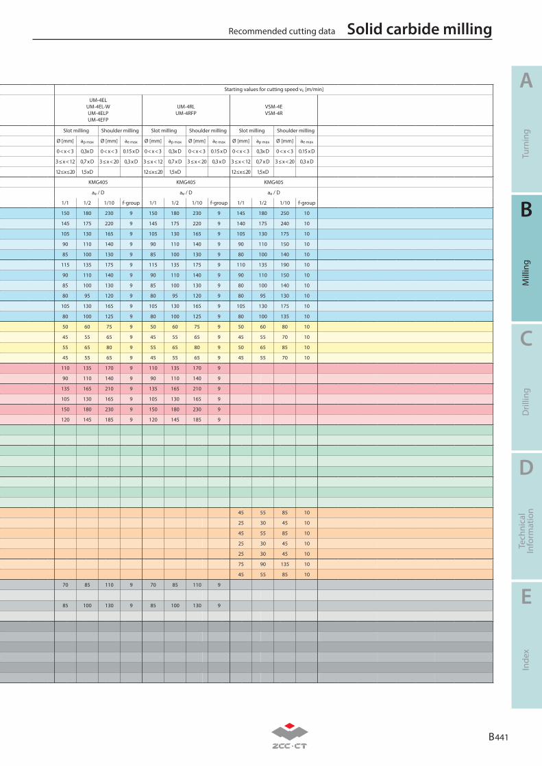
B 441
A
B
C
D
E
Turn
ing
Mill
ing
Dril
ling
Tech
nica
lIn
form
atio
nIn
dex
Recommended cutting data Solid carbide milling
Material group Composition / structure / heat treatmentBrinell
hardness HB
Mac
hini
ng g
roup
P
Unalloyed steel
ca. 0,15 % C annealed 125 1
ca. 0,45 % C annealed 190 2
ca. 0,45 % C tempered 250 3
ca. 0,75 % C annealed 270 4
ca. 0,75 % C tempered 300 5
Low-alloyed steel
annealed 180 6
tempered 275 7
tempered 300 8
tempered 350 9
High-alloyed steel and high-alloyed tool steel
annealed 200 10
hardened and tempered 325 11
M Stainless steel
ferritic/martensitic annealed 200 12
martensitic tempered 240 13
austenitic quench hardened 180 14
austenitic-ferritic 230 15
K
Grey cast ironperlitic/ferritic 180 16
perlitic (martensitic) 260 17
Cast iron with spheroidal graphiteferritic 160 18
perlitic 250 19
Malleable cast ironferritic 130 20
perlitic 230 21
N
Aluminium wrought alloyscannot be hardened 60 22
hardenable hardened 100 23
Cast aluminium alloys
≤ 12 % Si, cannot be hardened 75 24
≤ 12 % Si, hardenable hardened 90 25
> 12 % Si, cannot be hardened 130 26
Copper and copper alloys(bronze/brass)
machining steel, PB> 1% 110 27
CuZn, CuSnZn 90 28
CuSn, Pb-free copper, electrolytic copper 100 29
SHeat-resistant alloys
Fe-based alloysannealed 200 30
hardened 280 31
Ni or Co bass
annealed 250 32
hardened 350 33
cast 320 34
Titanium alloyspure titanium Rm 400 35
α and β alloys hardened Rm 1050 36
HHardened steel
hardened and tempered 55 HRC 37
hardened and tempered 60 HRC 38
Hard cast iron cast 400 39
Hardened cast iron hardened and tempered 55 HRC 40
X Non-metallic materials
Thermoplasts 41
Thermosetting plastics 42
Plastic, glass-fibre reinforced GFRP 43
Plastic, carbon fibre reinforced CFRP 44
Graphite 45
Wood 46
Note: The given cutting values are guide values, which were determined under ideal conditions. The values have to be adapted in individual cases. Feed rate recommendations on page B240. For examples of material for cutting tool groups view page D22.
Starting values for cutting speed vc [m/min]
UM-4ELUM-4EL-WUM-4ELPUM-4EFP
UM-4RLUM-4RFP
VSM-4EVSM-4R
Slot milling Shoulder milling Slot milling Shoulder milling Slot milling Shoulder milling
Ø [mm] ap max Ø [mm] ae max Ø [mm] ap max Ø [mm] ae max Ø [mm] ap max Ø [mm] ae max
0 < x < 3 0,3x D 0 < x < 3 0.15 x D 0 < x < 3 0,3x D 0 < x < 3 0.15 x D 0 < x < 3 0,3x D 0 < x < 3 0.15 x D
3 ≤ x < 12 0,7 x D 3 ≤ x < 20 0,3 x D 3 ≤ x < 12 0,7 x D 3 ≤ x < 20 0,3 x D 3 ≤ x < 12 0,7 x D 3 ≤ x < 20 0,3 x D
12 ≤ x ≤ 20 1,5 x D 12 ≤ x ≤ 20 1,5 x D 12 ≤ x ≤ 20 1,5 x D
KMG405 KMG405 KMG405
ae / D ae / D ae / D
1/1 1/2 1/10 f-group 1/1 1/2 1/10 f-group 1/1 1/2 1/10 f-group
150 180 230 9 150 180 230 9 145 180 250 10
145 175 220 9 145 175 220 9 140 175 240 10
105 130 165 9 105 130 165 9 105 130 175 10
90 110 140 9 90 110 140 9 90 110 150 10
85 100 130 9 85 100 130 9 80 100 140 10
115 135 175 9 115 135 175 9 110 135 190 10
90 110 140 9 90 110 140 9 90 110 150 10
85 100 130 9 85 100 130 9 80 100 140 10
80 95 120 9 80 95 120 9 80 95 130 10
105 130 165 9 105 130 165 9 105 130 175 10
80 100 125 9 80 100 125 9 80 100 135 10
50 60 75 9 50 60 75 9 50 60 80 10
45 55 65 9 45 55 65 9 45 55 70 10
55 65 80 9 55 65 80 9 50 65 85 10
45 55 65 9 45 55 65 9 45 55 70 10
110 135 170 9 110 135 170 9
90 110 140 9 90 110 140 9
135 165 210 9 135 165 210 9
105 130 165 9 105 130 165 9
150 180 230 9 150 180 230 9
120 145 185 9 120 145 185 9
45 55 85 10
25 30 45 10
45 55 85 10
25 30 45 10
25 30 45 10
75 90 135 10
45 55 85 10
70 85 110 9 70 85 110 9
85 100 130 9 85 100 130 9

B 442
A
B
C
D
E
Turn
ing
Mill
ing
Dril
ling
Tech
nica
lIn
form
atio
nIn
dex
Recommended cutting dataSolid carbide milling
Material group Composition / structure / heat treatmentBrinell
hardness HB
Mac
hini
ng g
roup
P
Unalloyed steel
ca. 0,15 % C annealed 125 1
ca. 0,45 % C annealed 190 2
ca. 0,45 % C tempered 250 3
ca. 0,75 % C annealed 270 4
ca. 0,75 % C tempered 300 5
Low-alloyed steel
annealed 180 6
tempered 275 7
tempered 300 8
tempered 350 9
High-alloyed steel and high-alloyed tool steel
annealed 200 10
hardened and tempered 325 11
M Stainless steel
ferritic/martensitic annealed 200 12
martensitic tempered 240 13
austenitic quench hardened 180 14
austenitic-ferritic 230 15
K
Grey cast ironperlitic/ferritic 180 16
perlitic (martensitic) 260 17
Cast iron with spheroidal graphiteferritic 160 18
perlitic 250 19
Malleable cast ironferritic 130 20
perlitic 230 21
N
Aluminium wrought alloyscannot be hardened 60 22
hardenable hardened 100 23
Cast aluminium alloys
≤ 12 % Si, cannot be hardened 75 24
≤ 12 % Si, hardenable hardened 90 25
> 12 % Si, cannot be hardened 130 26
Copper and copper alloys(bronze/brass)
machining steel, PB> 1% 110 27
CuZn, CuSnZn 90 28
CuSn, Pb-free copper, electrolytic copper 100 29
SHeat-resistant alloys
Fe-based alloysannealed 200 30
hardened 280 31
Ni or Co bass
annealed 250 32
hardened 350 33
cast 320 34
Titanium alloyspure titanium Rm 400 35
α and β alloys hardened Rm 1050 36
HHardened steel
hardened and tempered 55 HRC 37
hardened and tempered 60 HRC 38
Hard cast iron cast 400 39
Hardened cast iron hardened and tempered 55 HRC 40
X Non-metallic materials
Thermoplasts 41
Thermosetting plastics 42
Plastic, glass-fibre reinforced GFRP 43
Plastic, carbon fibre reinforced CFRP 44
Graphite 45
Wood 46
Note: The given cutting values are guide values, which were determined under ideal conditions. The values have to be adapted in individual cases. Feed rate recommendations on page B444. For examples of material for cutting tool groups view page D22.
Deburring cutters – FM seriesStarting values for cutting speed vc [m/min]
5501 / 56015501 / 5601
5601
KMG303
ae / D
1/1 1/2 1/10 f-group
230 11
220 11
165 11
140 11
130 11
175 11
140 11
130 11
120 11
165 11
125 11
75 11
65 11
80 11
65 11
170 11
140 11
210 11
165 11
230 11
185 11
1200 11
720 11
480 11
600 11
180 11
360 11
420 11
360 11
B 443
A
B
C
D
E
Turn
ing
Mill
ing
Dril
ling
Tech
nica
lIn
form
atio
nIn
dex
Recommended cutting data Solid carbide milling
Material group Composition / structure / heat treatmentBrinell
hardness HB
Mac
hini
ng g
roup
P
Unalloyed steel
ca. 0,15 % C annealed 125 1
ca. 0,45 % C annealed 190 2
ca. 0,45 % C tempered 250 3
ca. 0,75 % C annealed 270 4
ca. 0,75 % C tempered 300 5
Low-alloyed steel
annealed 180 6
tempered 275 7
tempered 300 8
tempered 350 9
High-alloyed steel and high-alloyed tool steel
annealed 200 10
hardened and tempered 325 11
M Stainless steel
ferritic/martensitic annealed 200 12
martensitic tempered 240 13
austenitic quench hardened 180 14
austenitic-ferritic 230 15
K
Grey cast ironperlitic/ferritic 180 16
perlitic (martensitic) 260 17
Cast iron with spheroidal graphiteferritic 160 18
perlitic 250 19
Malleable cast ironferritic 130 20
perlitic 230 21
N
Aluminium wrought alloyscannot be hardened 60 22
hardenable hardened 100 23
Cast aluminium alloys
≤ 12 % Si, cannot be hardened 75 24
≤ 12 % Si, hardenable hardened 90 25
> 12 % Si, cannot be hardened 130 26
Copper and copper alloys(bronze/brass)
machining steel, PB> 1% 110 27
CuZn, CuSnZn 90 28
CuSn, Pb-free copper, electrolytic copper 100 29
SHeat-resistant alloys
Fe-based alloysannealed 200 30
hardened 280 31
Ni or Co bass
annealed 250 32
hardened 350 33
cast 320 34
Titanium alloyspure titanium Rm 400 35
α and β alloys hardened Rm 1050 36
HHardened steel
hardened and tempered 55 HRC 37
hardened and tempered 60 HRC 38
Hard cast iron cast 400 39
Hardened cast iron hardened and tempered 55 HRC 40
X Non-metallic materials
Thermoplasts 41
Thermosetting plastics 42
Plastic, glass-fibre reinforced GFRP 43
Plastic, carbon fibre reinforced CFRP 44
Graphite 45
Wood 46
Note: The given cutting values are guide values, which were determined under ideal conditions. The values have to be adapted in individual cases. Feed rate recommendations on page B444. For examples of material for cutting tool groups view page D22.
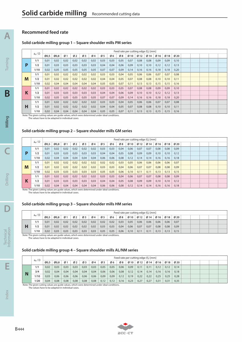
B 444
A
B
C
D
E
Turn
ing
Mill
ing
Dril
ling
Tech
nica
lIn
form
atio
nIn
dex
ae / DFeed rate per cutting edge (fz) [mm]
Ø0,5 Ø0,8 Ø 1 Ø 2 Ø 3 Ø 4 Ø 5 Ø 6 Ø 8 Ø 10 Ø 12 Ø 14 Ø 16 Ø 18 Ø 20
P1/1 0,01 0,02 0,02 0,02 0,02 0,02 0,03 0,03 0,05 0,07 0,08 0,08 0,09 0,09 0,10
1/2 0,01 0,03 0,03 0,03 0,03 0,03 0,04 0,04 0,06 0,09 0,10 0,10 0,12 0,12 0,13
1/10 0,02 0,05 0,05 0,05 0,05 0,05 0,07 0,07 0,09 0,14 0,16 0,16 0,18 0,18 0,20
M1/1 0,01 0,02 0,02 0,02 0,02 0,02 0,03 0,03 0,04 0,05 0,06 0,06 0,07 0,07 0,08
1/2 0,01 0,02 0,02 0,02 0,02 0,02 0,04 0,04 0,05 0,07 0,08 0,08 0,10 0,10 0,11
1/10 0,02 0,04 0,04 0,04 0,04 0,04 0,05 0,05 0,07 0,11 0,13 0,13 0,15 0,15 0,16
K1/1 0,01 0,02 0,02 0,02 0,02 0,02 0,03 0,03 0,05 0,07 0,08 0,08 0,09 0,09 0,10
1/2 0,01 0,03 0,03 0,03 0,03 0,03 0,04 0,04 0,06 0,09 0,10 0,10 0,12 0,12 0,13
1/10 0,02 0,05 0,05 0,05 0,05 0,05 0,07 0,07 0,09 0,14 0,16 0,16 0,18 0,18 0,20
H1/1 0,01 0,02 0,02 0,02 0,02 0,02 0,03 0,03 0,04 0,05 0,06 0,06 0,07 0,07 0,08
1/2 0,01 0,02 0,02 0,02 0,02 0,02 0,04 0,04 0,05 0,07 0,08 0,08 0,10 0,10 0,11
1/10 0,02 0,04 0,04 0,04 0,04 0,04 0,05 0,05 0,07 0,11 0,13 0,13 0,15 0,15 0,16Note: The given cutting values are guide values, which were determined under ideal conditions.
The values have to be adapted in individual cases.
ae / DFeed rate per cutting edge (fz) [mm]
Ø0,5 Ø0,8 Ø 1 Ø 2 Ø 3 Ø 4 Ø 5 Ø 6 Ø 8 Ø 10 Ø 12 Ø 14 Ø 16 Ø 18 Ø 20
H1/1 0,01 0,02 0,02 0,02 0,02 0,02 0,02 0,02 0,03 0,05 0,06 0,06 0,06 0,06 0,07
1/2 0,01 0,02 0,02 0,02 0,02 0,02 0,03 0,03 0,04 0,06 0,07 0,07 0,08 0,08 0,09
1/10 0,02 0,03 0,03 0,03 0,03 0,03 0,05 0,05 0,06 0,10 0,11 0,11 0,13 0,13 0,15Note: The given cutting values are guide values, which were determined under ideal conditions.
The values have to be adapted in individual cases.
ae / DFeed rate per cutting edge (fz) [mm]
Ø0,5 Ø0,8 Ø 1 Ø 2 Ø 3 Ø 4 Ø 5 Ø 6 Ø 8 Ø 10 Ø 12 Ø 14 Ø 16 Ø 18 Ø 20
P1/1 0,01 0,02 0,02 0,02 0,02 0,02 0,03 0,03 0,04 0,06 0,07 0,07 0,08 0,08 0,09
1/2 0,01 0,03 0,03 0,03 0,03 0,03 0,04 0,04 0,05 0,08 0,09 0,09 0,10 0,10 0,12
1/10 0,02 0,04 0,04 0,04 0,04 0,04 0,06 0,06 0,08 0,12 0,14 0,14 0,16 0,16 0,18
M1/1 0,01 0,02 0,02 0,02 0,02 0,02 0,02 0,02 0,03 0,05 0,06 0,06 0,06 0,06 0,07
1/2 0,01 0,02 0,02 0,02 0,02 0,02 0,03 0,03 0,04 0,06 0,07 0,07 0,08 0,08 0,09
1/10 0,02 0,03 0,03 0,03 0,03 0,03 0,05 0,05 0,06 0,10 0,11 0,11 0,13 0,13 0,15
K1/1 0,01 0,02 0,02 0,02 0,02 0,02 0,03 0,03 0,04 0,06 0,07 0,07 0,08 0,08 0,09
1/2 0,01 0,03 0,03 0,03 0,03 0,03 0,04 0,04 0,05 0,08 0,09 0,09 0,10 0,10 0,12
1/10 0,02 0,04 0,04 0,04 0,04 0,04 0,06 0,06 0,08 0,12 0,14 0,14 0,16 0,16 0,18Note: The given cutting values are guide values, which were determined under ideal conditions.
The values have to be adapted in individual cases.
ae / DFeed rate per cutting edge (fz) [mm]
Ø0,5 Ø0,8 Ø 1 Ø 2 Ø 3 Ø 4 Ø 5 Ø 6 Ø 8 Ø 10 Ø 12 Ø 14 Ø 16 Ø 18 Ø 20
N1/1 0,02 0,03 0,03 0,03 0,03 0,03 0,05 0,05 0,06 0,09 0,11 0,11 0,12 0,12 0,14
3/4 0,02 0,04 0,04 0,04 0,04 0,04 0,06 0,06 0,08 0,12 0,14 0,14 0,16 0,16 0,18
1/10 0,03 0,06 0,06 0,06 0,06 0,06 0,09 0,09 0,12 0,19 0,22 0,22 0,25 0,25 0,28
1/20 0,04 0,08 0,08 0,08 0,08 0,08 0,12 0,12 0,16 0,23 0,27 0,27 0,31 0,31 0,35Note: The given cutting values are guide values, which were determined under ideal conditions.
The values have to be adapted in individual cases.
Solid carbide milling group 1 – Square shoulder mills PM series
Solid carbide milling group 3 – Square shoulder mills HM series
Solid carbide milling group 4 – Square shoulder mills AL/NM series
Solid carbide milling group 2 – Square shoulder mills GM series
Recommended cutting dataSolid carbide milling
Recommend feed rate
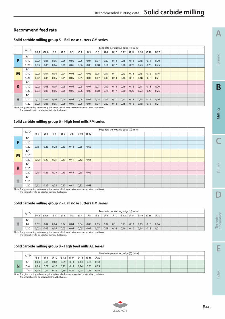
B 445
A
B
C
D
E
Turn
ing
Mill
ing
Dril
ling
Tech
nica
lIn
form
atio
nIn
dex
ae / DFeed rate per cutting edge (fz) [mm]
Ø0,5 Ø0,8 Ø 1 Ø 2 Ø 3 Ø 4 Ø 5 Ø 6 Ø 8 Ø 10 Ø 12 Ø 14 Ø 16 Ø 18 Ø 20
P1/1
1/10 0,02 0,05 0,05 0,05 0,05 0,05 0,07 0,07 0,09 0,14 0,16 0,16 0,18 0,18 0,20
1/20 0,03 0,06 0,06 0,06 0,06 0,06 0,08 0,08 0,11 0,17 0,20 0,20 0,23 0,23 0,25
M1/1
1/10 0,02 0,04 0,04 0,04 0,04 0,04 0,05 0,05 0,07 0,11 0,13 0,13 0,15 0,15 0,16
1/20 0,02 0,05 0,05 0,05 0,05 0,05 0,07 0,07 0,09 0,14 0,16 0,16 0,18 0,18 0,21
K1/1
1/10 0,02 0,05 0,05 0,05 0,05 0,05 0,07 0,07 0,09 0,14 0,16 0,16 0,18 0,18 0,20
1/20 0,03 0,06 0,06 0,06 0,06 0,06 0,08 0,08 0,11 0,17 0,20 0,20 0,23 0,23 0,25
H1/1
1/10 0,02 0,04 0,04 0,04 0,04 0,04 0,05 0,05 0,07 0,11 0,13 0,13 0,15 0,15 0,16
1/20 0,02 0,05 0,05 0,05 0,05 0,05 0,07 0,07 0,09 0,14 0,16 0,16 0,18 0,18 0,21Note: The given cutting values are guide values, which were determined under ideal conditions.
The values have to be adapted in individual cases.
ae / DFeed rate per cutting edge (fz) [mm]
Ø 3 Ø 4 Ø 5 Ø 6 Ø 8 Ø 10 Ø 12
P1/1
1/10
1/20 0,15 0,25 0,28 0,33 0,44 0,55 0,66
M1/1
1/10
1/20 0,12 0,22 0,25 0,30 0,41 0,52 0,63
K1/1
1/10
1/20 0,15 0,25 0,28 0,33 0,44 0,55 0,66
H1/1
1/10
1/20 0,12 0,22 0,25 0,30 0,41 0,52 0,63Note: The given cutting values are guide values, which were determined under ideal conditions.
The values have to be adapted in individual cases.
ae / DFeed rate per cutting edge (fz) [mm]
Ø0,5 Ø0,8 Ø 1 Ø 2 Ø 3 Ø 4 Ø 5 Ø 6 Ø 8 Ø 10 Ø 12 Ø 14 Ø 16 Ø 18 Ø 20
H1/1
1/2 0,02 0,04 0,04 0,04 0,04 0,04 0,05 0,05 0,07 0,11 0,13 0,13 0,15 0,15 0,16
1/10 0,02 0,05 0,05 0,05 0,05 0,05 0,07 0,07 0,09 0,14 0,16 0,16 0,18 0,18 0,21Note: The given cutting values are guide values, which were determined under ideal conditions.
The values have to be adapted in individual cases.
ae / DFeed rate per cutting edge (fz) [mm]
Ø 6 Ø 8 Ø 10 Ø 12 Ø 14 Ø 16 Ø 18 Ø 20
N1/1 0,04 0,05 0,08 0,09 0,11 0,13 0,16 0,18
3/4 0,05 0,07 0,10 0,12 0,14 0,16 0,20 0,23
1/10 0,08 0,11 0,16 0,19 0,22 0,25 0,31 0,36Note: The given cutting values are guide values, which were determined under ideal conditions.
The values have to be adapted in individual cases.
Solid carbide milling group 5 – Ball nose cutters GM series
Solid carbide milling group 6 – High feed mills PM series
Solid carbide milling group 7 – Ball nose cutters HM series
Solid carbide milling group 8 – High feed mills AL series
Recommended cutting data Solid carbide milling
Recommend feed rate
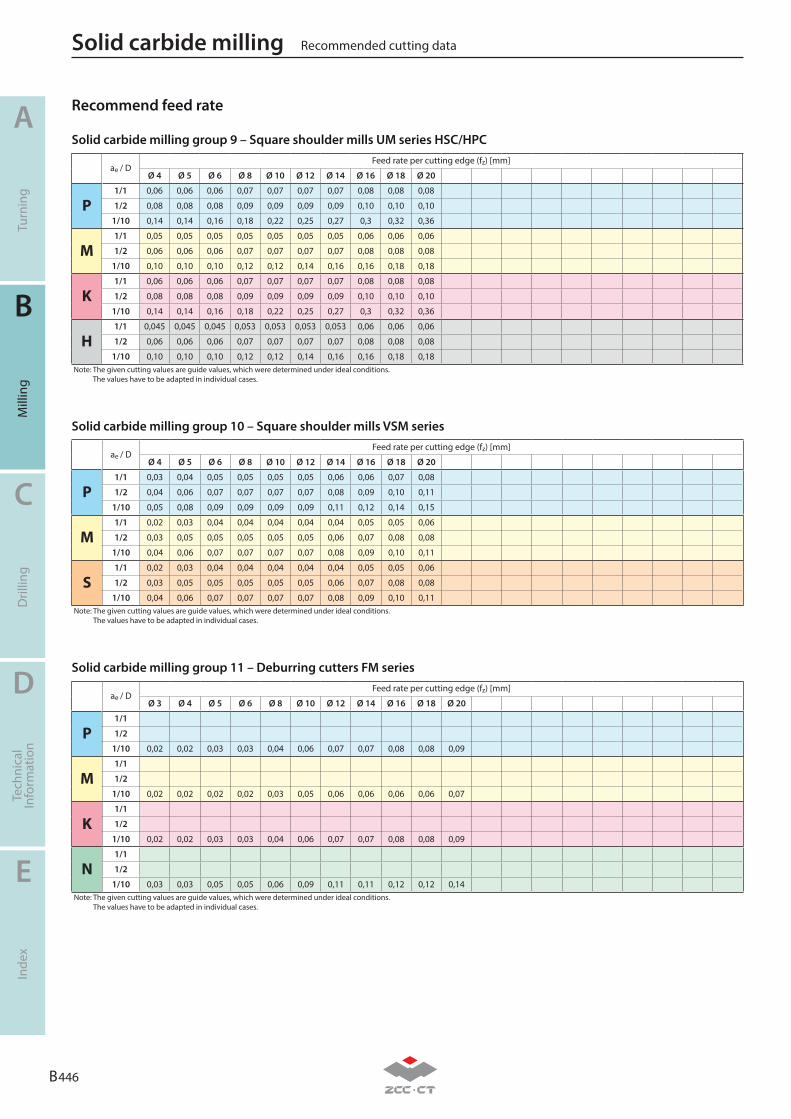
B 446
A
B
C
D
E
Turn
ing
Mill
ing
Dril
ling
Tech
nica
lIn
form
atio
nIn
dex
Solid carbide milling group 9 – Square shoulder mills UM series HSC/HPC
Solid carbide milling group 10 – Square shoulder mills VSM series
Solid carbide milling group 11 – Deburring cutters FM series
ae / DFeed rate per cutting edge (fz) [mm]
Ø 4 Ø 5 Ø 6 Ø 8 Ø 10 Ø 12 Ø 14 Ø 16 Ø 18 Ø 20
P1/1 0,03 0,04 0,05 0,05 0,05 0,05 0,06 0,06 0,07 0,08
1/2 0,04 0,06 0,07 0,07 0,07 0,07 0,08 0,09 0,10 0,11
1/10 0,05 0,08 0,09 0,09 0,09 0,09 0,11 0,12 0,14 0,15
M1/1 0,02 0,03 0,04 0,04 0,04 0,04 0,04 0,05 0,05 0,06
1/2 0,03 0,05 0,05 0,05 0,05 0,05 0,06 0,07 0,08 0,08
1/10 0,04 0,06 0,07 0,07 0,07 0,07 0,08 0,09 0,10 0,11
S1/1 0,02 0,03 0,04 0,04 0,04 0,04 0,04 0,05 0,05 0,06
1/2 0,03 0,05 0,05 0,05 0,05 0,05 0,06 0,07 0,08 0,08
1/10 0,04 0,06 0,07 0,07 0,07 0,07 0,08 0,09 0,10 0,11Note: The given cutting values are guide values, which were determined under ideal conditions.
The values have to be adapted in individual cases.
ae / DFeed rate per cutting edge (fz) [mm]
Ø 4 Ø 5 Ø 6 Ø 8 Ø 10 Ø 12 Ø 14 Ø 16 Ø 18 Ø 20
P1/1 0,06 0,06 0,06 0,07 0,07 0,07 0,07 0,08 0,08 0,08
1/2 0,08 0,08 0,08 0,09 0,09 0,09 0,09 0,10 0,10 0,10
1/10 0,14 0,14 0,16 0,18 0,22 0,25 0,27 0,3 0,32 0,36
M1/1 0,05 0,05 0,05 0,05 0,05 0,05 0,05 0,06 0,06 0,06
1/2 0,06 0,06 0,06 0,07 0,07 0,07 0,07 0,08 0,08 0,08
1/10 0,10 0,10 0,10 0,12 0,12 0,14 0,16 0,16 0,18 0,18
K1/1 0,06 0,06 0,06 0,07 0,07 0,07 0,07 0,08 0,08 0,08
1/2 0,08 0,08 0,08 0,09 0,09 0,09 0,09 0,10 0,10 0,10
1/10 0,14 0,14 0,16 0,18 0,22 0,25 0,27 0,3 0,32 0,36
H1/1 0,045 0,045 0,045 0,053 0,053 0,053 0,053 0,06 0,06 0,06
1/2 0,06 0,06 0,06 0,07 0,07 0,07 0,07 0,08 0,08 0,08
1/10 0,10 0,10 0,10 0,12 0,12 0,14 0,16 0,16 0,18 0,18Note: The given cutting values are guide values, which were determined under ideal conditions.
The values have to be adapted in individual cases.
ae / DFeed rate per cutting edge (fz) [mm]
Ø 3 Ø 4 Ø 5 Ø 6 Ø 8 Ø 10 Ø 12 Ø 14 Ø 16 Ø 18 Ø 20
P1/1
1/2
1/10 0,02 0,02 0,03 0,03 0,04 0,06 0,07 0,07 0,08 0,08 0,09
M1/1
1/2
1/10 0,02 0,02 0,02 0,02 0,03 0,05 0,06 0,06 0,06 0,06 0,07
K1/1
1/2
1/10 0,02 0,02 0,03 0,03 0,04 0,06 0,07 0,07 0,08 0,08 0,09
N1/1
1/2
1/10 0,03 0,03 0,05 0,05 0,06 0,09 0,11 0,11 0,12 0,12 0,14Note: The given cutting values are guide values, which were determined under ideal conditions.
The values have to be adapted in individual cases.
Recommended cutting dataSolid carbide milling
Recommend feed rate
B 447
A
B
C
D
E
Turn
ing
Mill
ing
Dril
ling
Inde
xTe
chni
cal
Info
rmat
ion
Technical information
Trouble shooting – milling B448
Technical information – milling B449-B460
Form nonstandard order – milling B461-B462 B
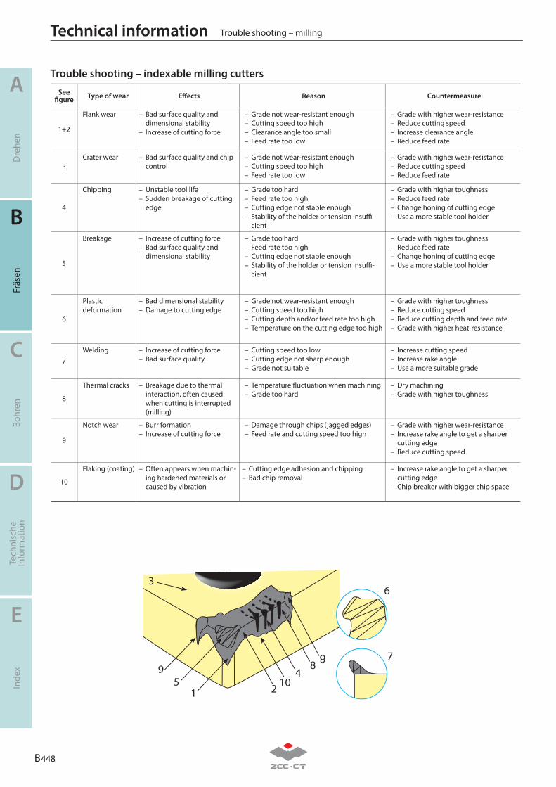
A
B
C
D
E
Dre
hen
Fräs
enBo
hren
Tech
nisc
heIn
form
atio
nIn
dex
B 448
Trouble shooting – millingTechnical information
See fi gure Type of wear Eff ects Reason Countermeasure
1+2
Flank wear – Bad surface quality and dimensional stability
– Increase of cutting force
– Grade not wear-resistant enough– Cutting speed too high– Clearance angle too small– Feed rate too low
– Grade with higher wear-resistance– Reduce cutting speed– Increase clearance angle– Reduce feed rate
3Crater wear – Bad surface quality and chip
control– Grade not wear-resistant enough– Cutting speed too high– Feed rate too low
– Grade with higher wear-resistance– Reduce cutting speed– Reduce feed rate
4
Chipping – Unstable tool life– Sudden breakage of cutting
edge
– Grade too hard– Feed rate too high– Cutting edge not stable enough– Stability of the holder or tension insuffi -
cient
– Grade with higher toughness– Reduce feed rate– Change honing of cutting edge– Use a more stable tool holder
5
Breakage – Increase of cutting force– Bad surface quality and
dimensional stability
– Grade too hard– Feed rate too high– Cutting edge not stable enough– Stability of the holder or tension insuffi -
cient
– Grade with higher toughness– Reduce feed rate– Change honing of cutting edge– Use a more stable tool holder
6
Plastic deformation
– Bad dimensional stability– Damage to cutting edge
– Grade not wear-resistant enough– Cutting speed too high– Cutting depth and/or feed rate too high– Temperature on the cutting edge too high
– Grade with higher toughness– Reduce cutting speed– Reduce cutting depth and feed rate– Grade with higher heat-resistance
7Welding – Increase of cutting force
– Bad surface quality– Cutting speed too low– Cutting edge not sharp enough– Grade not suitable
– Increase cutting speed– Increase rake angle– Use a more suitable grade
8
Thermal cracks – Breakage due to thermal interaction, often caused when cutting is interrupted (milling)
– Temperature fl uctuation when machining– Grade too hard
– Dry machining– Grade with higher toughness
9
Notch wear – Burr formation– Increase of cutting force
– Damage through chips (jagged edges)– Feed rate and cutting speed too high
– Grade with higher wear-resistance– Increase rake angle to get a sharper
cutting edge– Reduce cutting speed
10
Flaking (coating) – Often appears when machin-ing hardened materials or caused by vibration
– Cutting edge adhesion and chipping– Bad chip removal
– Increase rake angle to get a sharper cutting edge
– Chip breaker with bigger chip space
Trouble shooting – indexable milling cutters
6
7984
1025
1
9
3
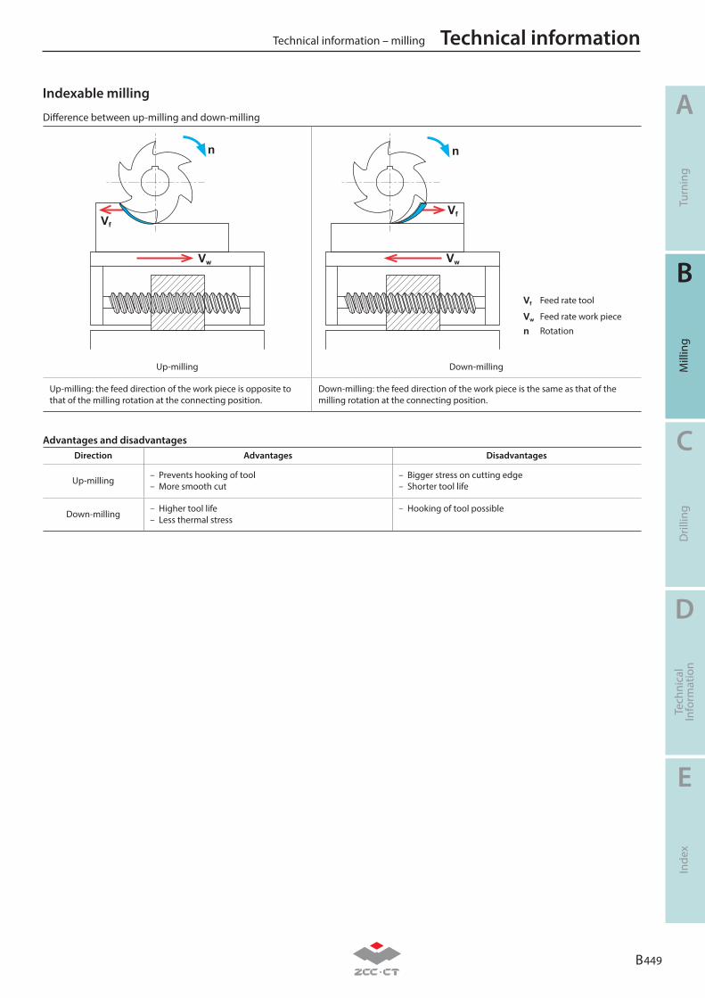
B 449
A
B
C
D
E
Turn
ing
Mill
ing
Dril
ling
Tech
nica
lIn
form
atio
nIn
dex
Technical information – milling Technical information
Advantages and disadvantagesDirection Advantages Disadvantages
Up-milling– Prevents hooking of tool– More smooth cut
– Bigger stress on cutting edge– Shorter tool life
Down-milling– Higher tool life– Less thermal stress
– Hooking of tool possible
Difference between up-milling and down-milling
Vf
Vw
n
Vf
Vw
Vf Feed rate tool
Vw Feed rate work piece
n Rotation
n
Up-milling Down-milling
Up-milling: the feed direction of the work piece is opposite to that of the milling rotation at the connecting position.
Down-milling: the feed direction of the work piece is the same as that of the milling rotation at the connecting position.
Indexable milling
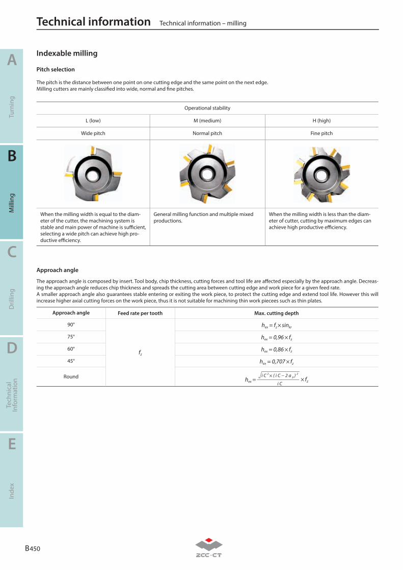
B 450
A
B
C
D
E
Turn
ing
Mill
ing
Dril
ling
Tech
nica
lIn
form
atio
nIn
dex
Technical information – millingTechnical information
Pitch selection
The pitch is the distance between one point on one cutting edge and the same point on the next edge. Milling cutters are mainly classifi ed into wide, normal and fi ne pitches.
Operational stability
L (low) M (medium) H (high)
Wide pitch Normal pitch Fine pitch
When the milling width is equal to the diam-eter of the cutter, the machining system is stable and main power of machine is suffi cient, selecting a wide pitch can achieve high pro-ductive effi ciency.
General milling function and multiple mixed productions.
When the milling width is less than the diam-eter of cutter, cutting by maximum edges can achieve high productive effi ciency.
Approach angle
The approach angle is composed by insert. Tool body, chip thickness, cutting forces and tool life are aff ected especially by the approach angle. Decreas-ing the approach angle reduces chip thickness and spreads the cutting area between cutting edge and work piece for a given feed rate.A smaller approach angle also guarantees stable entering or exiting the work piece, to protect the cutting edge and extend tool life. However this will increase higher axial cutting forces on the work piece, thus it is not suitable for machining thin work piecees such as thin plates.
Approach angle Feed rate per tooth Max. cutting depth
90°
fz
hex = fz × sinkr
75° hex = 0,96 × fz
60° hex = 0,86 × fz
45° hex = 0,707 × fz
Round hex = i C 2 × ( i C − 2 a p ) 2
i C× fz
Indexable milling
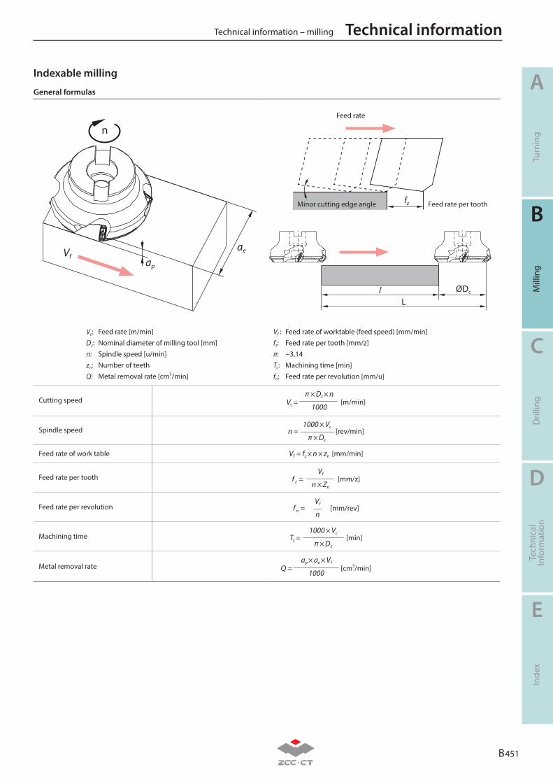
B 451
A
B
C
D
E
Turn
ing
Mill
ing
Dril
ling
Tech
nica
lIn
form
atio
nIn
dex
Technical information – milling Technical information
Indexable milling
General formulas
LØDcl
Minor cutting edge angle Feed rate per toothfz
Feed rate
ap
n
aeVf
Vc: Feed rate [m/min]Dc: Nominal diameter of milling tool [mm]n: Spindle speed [u/min]zn: Number of teethQ: Metal removal rate [cm3/min]
Vf : Feed rate of worktable (feed speed) [mm/min]fz: Feed rate per tooth [mm/z]π: ~3,14Tc: Machining time [min]fn: Feed rate per revolution [mm/u]
Cutting speed Vc =π × Dc × n
1000[m/min]
Spindle speed n =1000 × Vc
π × Dc
[rev/min]
Feed rate of work table Vf = fz × n × zn [mm/min]
Feed rate per tooth f z =Vf
n × Zn
[mm/z]
Feed rate per revolution f n =Vf
n[mm/rev]
Machining time Tc =1000 × Vc
π × Dc
[min]
Metal removal rate Q =ap × ae × Vf
1000[cm3/min]
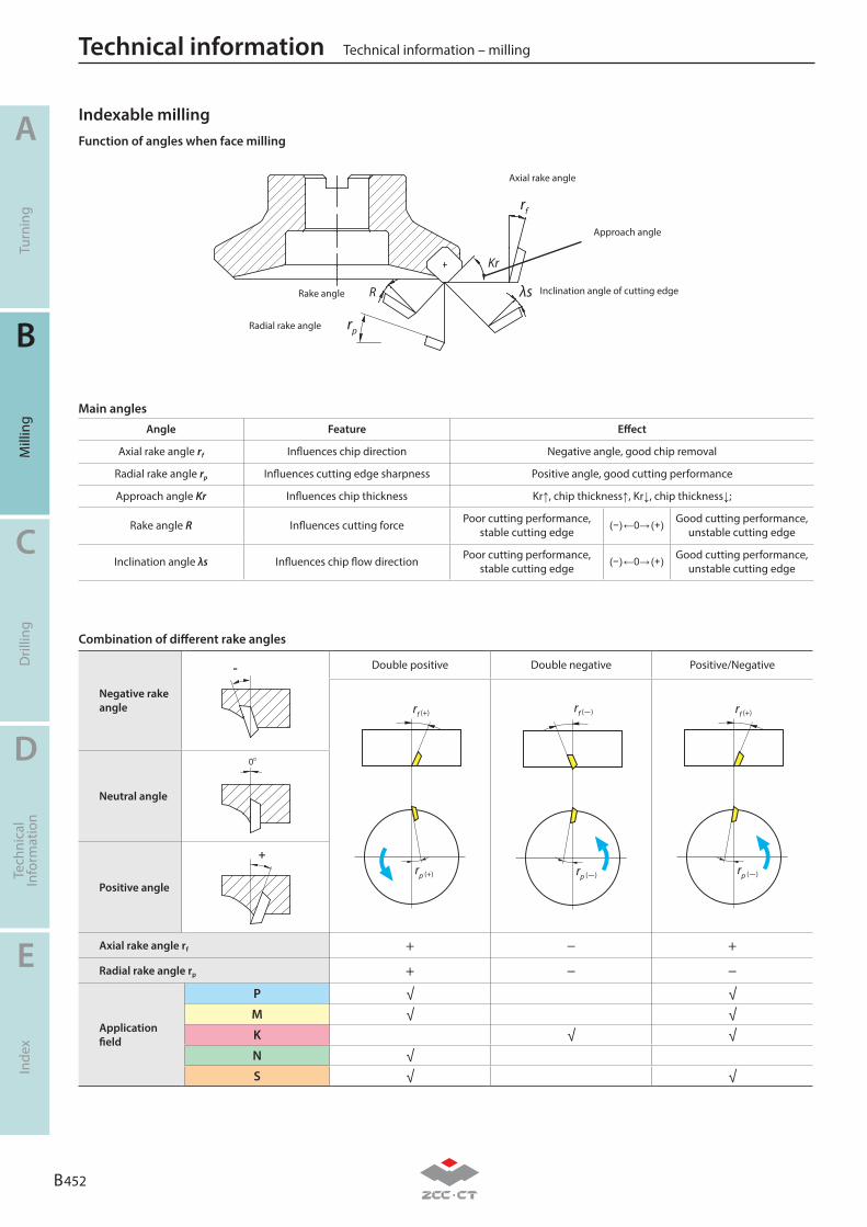
B 452
A
B
C
D
E
Turn
ing
Mill
ing
Dril
ling
Tech
nica
lIn
form
atio
nIn
dex
Technical information – millingTechnical information
Function of angles when face milling
Main angles
Angle Feature Effect
Axial rake angle rf Influences chip direction Negative angle, good chip removal
Radial rake angle rp Influences cutting edge sharpness Positive angle, good cutting performance
Approach angle Kr Influences chip thickness Kr↑, chip thickness↑, Kr↓, chip thickness↓;
Rake angle R Influences cutting force Poor cutting performance, stable cutting edge
(−) ←0→ (﹢) Good cutting performance, unstable cutting edge
Inclination angle λs Influences chip flow direction Poor cutting performance, stable cutting edge
(−) ←0→ (﹢) Good cutting performance, unstable cutting edge
Combination of different rake angles
Negative rake angle
- Double positive Double negative Positive/Negative
rf (+)
rp (+)
rf (-)
rp (-)
rf (+)
rp (-)
Neutral angle
0o
Positive angle
﹢
Axial rake angle rf + − +
Radial rake angle rp + − −
Application field
P √ √M √ √K √ √N √S √ √
rf
rp
Kr
λsR
Axial rake angle
Radial rake angle
Rake angle Inclination angle of cutting edge
Approach angle
Indexable milling
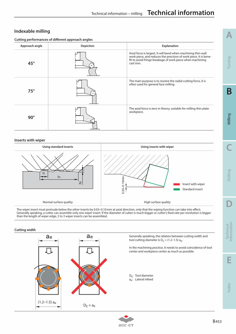
B 453
A
B
C
D
E
Turn
ing
Mill
ing
Dril
ling
Tech
nica
lIn
form
atio
nIn
dex
Technical information – milling Technical information
Cutting performances of different approach angles
Approach angle Depiction Explanation
45°
Axial force is largest. It will bend when machining thin-wall work piece, and reduces the precision of work piece. It is bene-fit to avoid fringe breakage of work piece when machining cast iron.
75°
The main purpose is to resolve the radial cutting force, it is often used for general face milling.
90°
The axial force is zero in theory, suitable for milling thin plate workpiece.
Inserts with wiper
Using standard inserts Using inserts with wiper
fzfn
Rz Insert with wiper
Standard insert
Normal surface quality High surface quality
The wiper insert must protrude below the other inserts by 0.03–0.10 mm at axial direction, only that the wiping function can take into effect.Generally speaking, a cutter can assemble only one wiper insert. If the diameter of cutter is much bigger or cutter’s feed rate per revolution is bigger than the length of wiper edge, 2 to 3 wiper inserts can be assembled.
Cutting width
(1.2–1.5) aeDc = ae
Generally speaking, the relation between cutting width and tool cutting diameter is Dc = (1.2–1.5) ae.
In the machining practice, it needs to avoid coincidence of tool center and workpiece center as much as possible.
Dc: Tool diameterae: Lateral infeed
Indexable milling
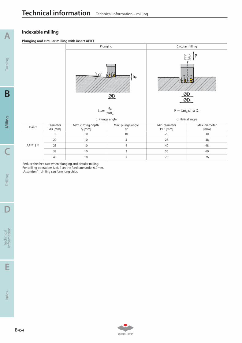
B 454
A
B
C
D
E
Turn
ing
Mill
ing
Dril
ling
Tech
nica
lIn
form
atio
nIn
dex
Technical information – millingTechnical information
Indexable milling
Plunging Circular milling
α° ap
ØD
P
ØDØD1
Lm = ap
tanαP = tanα x π x D1
α: Plunge angle α: Helical angle
Insert DiameterØD [mm]
Max. cutting depthap [mm]
Max. plunge angleα°
Min. diameterØD1 [mm]
Max. diameter[mm]
AP**11**
16 10 10 20 30
20 10 5 28 38
25 10 4 40 48
32 10 3 56 60
40 10 2 70 76
Reduce the feed rate when plunging and circular milling.For drilling operations (axial) set the feed rate under 0.2 mm.„Attention“ – drilling can form long chips.
Plunging and circular milling with insert APKT
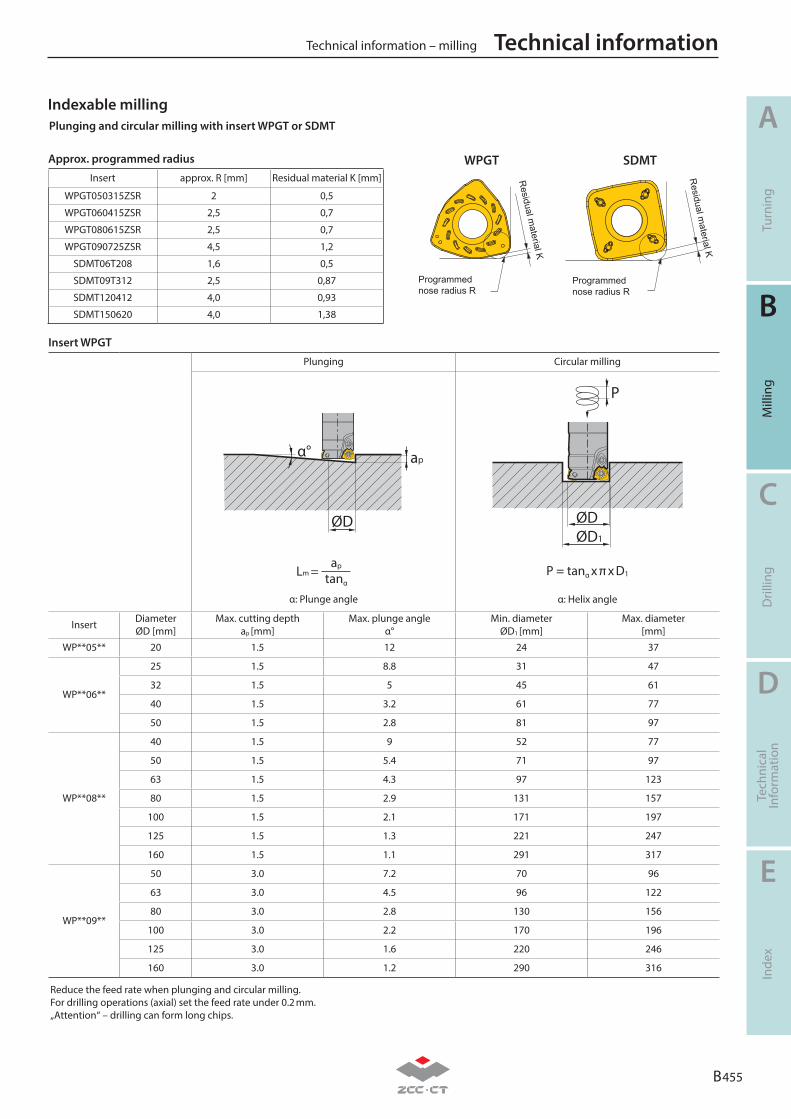
B 455
A
B
C
D
E
Turn
ing
Mill
ing
Dril
ling
Tech
nica
lIn
form
atio
nIn
dex
Technical information – milling Technical information
Insert WPGT
Plunging Circular milling
α° ap
ØD
P
ØDØD1
Lm = ap
tanαP = tanα x π x D1
α: Plunge angle α: Helix angle
Insert DiameterØD [mm]
Max. cutting depthap [mm]
Max. plunge angleα°
Min. diameterØD1 [mm]
Max. diameter[mm]
WP**05** 20 1.5 12 24 37
WP**06**
25 1.5 8.8 31 47
32 1.5 5 45 61
40 1.5 3.2 61 77
50 1.5 2.8 81 97
WP**08**
40 1.5 9 52 77
50 1.5 5.4 71 97
63 1.5 4.3 97 123
80 1.5 2.9 131 157
100 1.5 2.1 171 197
125 1.5 1.3 221 247
160 1.5 1.1 291 317
WP**09**
50 3.0 7.2 70 96
63 3.0 4.5 96 122
80 3.0 2.8 130 156
100 3.0 2.2 170 196
125 3.0 1.6 220 246
160 3.0 1.2 290 316
Reduce the feed rate when plunging and circular milling.For drilling operations (axial) set the feed rate under 0.2 mm.„Attention“ – drilling can form long chips.
Plunging and circular milling with insert WPGT or SDMT
WPGT SDMT
Programmed nose radius R
Residual m
aterial K
Programmed nose radius R
Residual m
aterial K
Indexable milling
Approx. programmed radius
Insert approx. R [mm] Residual material K [mm]
WPGT050315ZSR 2 0,5
WPGT060415ZSR 2,5 0,7
WPGT080615ZSR 2,5 0,7
WPGT090725ZSR 4,5 1,2
SDMT06T208 1,6 0,5
SDMT09T312 2,5 0,87
SDMT120412 4,0 0,93
SDMT150620 4,0 1,38
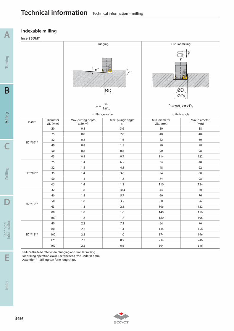
B 456
A
B
C
D
E
Turn
ing
Mill
ing
Dril
ling
Tech
nica
lIn
form
atio
nIn
dex
Technical information – millingTechnical information
Insert SDMT
Plunging Circular milling
α° ap
ØD
P
ØDØD1
Lm = ap
tanαP = tanα x π x D1
α: Plunge angle α: Helix angle
Insert DiameterØD (mm)
Max. cutting depthap [mm]
Max. plunge angleα°
Min. diameterØD1 [mm]
Max. diameter[mm]
SD**06**
20 0.8 3.6 30 38
25 0.8 2.8 40 48
32 0.8 1.6 52 60
40 0.8 1.1 70 78
50 0.8 0.8 90 98
63 0.8 0.7 114 122
SD**09**
25 1.4 6.5 34 48
32 1.4 4.5 48 62
35 1.4 3.6 54 68
50 1.4 1.8 84 98
63 1.4 1,3 110 124
SD**12**
32 1.8 10.4 44 60
40 1.8 5.7 60 76
50 1.8 3.5 80 96
63 1.8 2.5 106 122
80 1.8 1.6 140 156
100 1.8 1.2 180 196
SD**15**
40 2.2 7.3 54 76
80 2.2 1.4 134 156
100 2.2 1.0 174 196
125 2.2 0.9 234 246
160 2.2 0.6 304 316
Reduce the feed rate when plunging and circular milling.For drilling operations (axial) set the feed rate under 0,2 mm.„Attention“ – drilling can form long chips.
Indexable milling
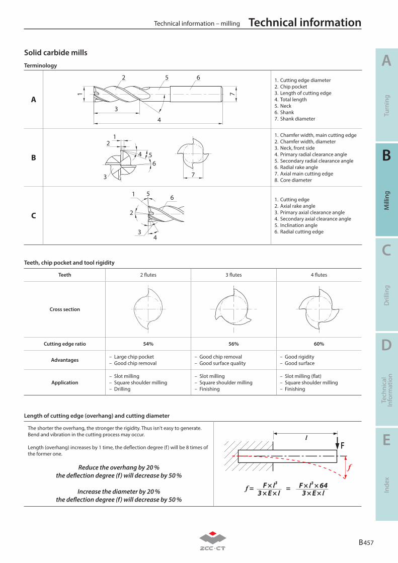
Teeth 2 flutes 3 flutes 4 flutes
Cross section
Cutting edge ratio 54% 56% 60%
Advantages– Large chip pocket– Good chip removal
– Good chip removal– Good surface quality
– Good rigidity– Good surface
Application– Slot milling– Square shoulder milling– Drilling
– Slot milling– Square shoulder milling– Finishing
– Slot milling (flat)– Square shoulder milling– Finishing
Solid carbide mills
Teeth, chip pocket and tool rigidity
Length of cutting edge (overhang) and cutting diameter
The shorter the overhang, the stronger the rigidity. Thus isn't easy to generate. Bend and vibration in the cutting process may occur.
Length (overhang) increases by 1 time, the deflection degree (f ) will be 8 times of the former one.
3 × E × l 3 × E × lF × l3 F × l3 × 64f = =
f
lF
Reduce the overhang by 20 %the deflection degree (f) will decrease by 50 %
Increase the diameter by 20 %the deflection degree (f) will decrease by 50 %
Terminology
A
12
7
65
3
4
1. Cutting edge diameter2. Chip pocket3. Length of cutting edge4. Total length5. Neck6. Shank7. Shank diameter
B
7
1
65
2
4
3
1. Chamfer width, main cutting edge2. Chamfer width, diameter3. Neck, front side4. Primary radial clearance angle5. Secondary radial clearance angle6. Radial rake angle7. Axial main cutting edge8. Core diameter
C
1 65
2
43
1. Cutting edge2. Axial rake angle3. Primary axial clearance angle4. Secondary axial clearance angle5. Inclination angle6. Radial cutting edge
B 457
A
B
C
D
E
Turn
ing
Mill
ing
Dril
ling
Tech
nica
lIn
form
atio
nIn
dex
Technical information – milling Technical information
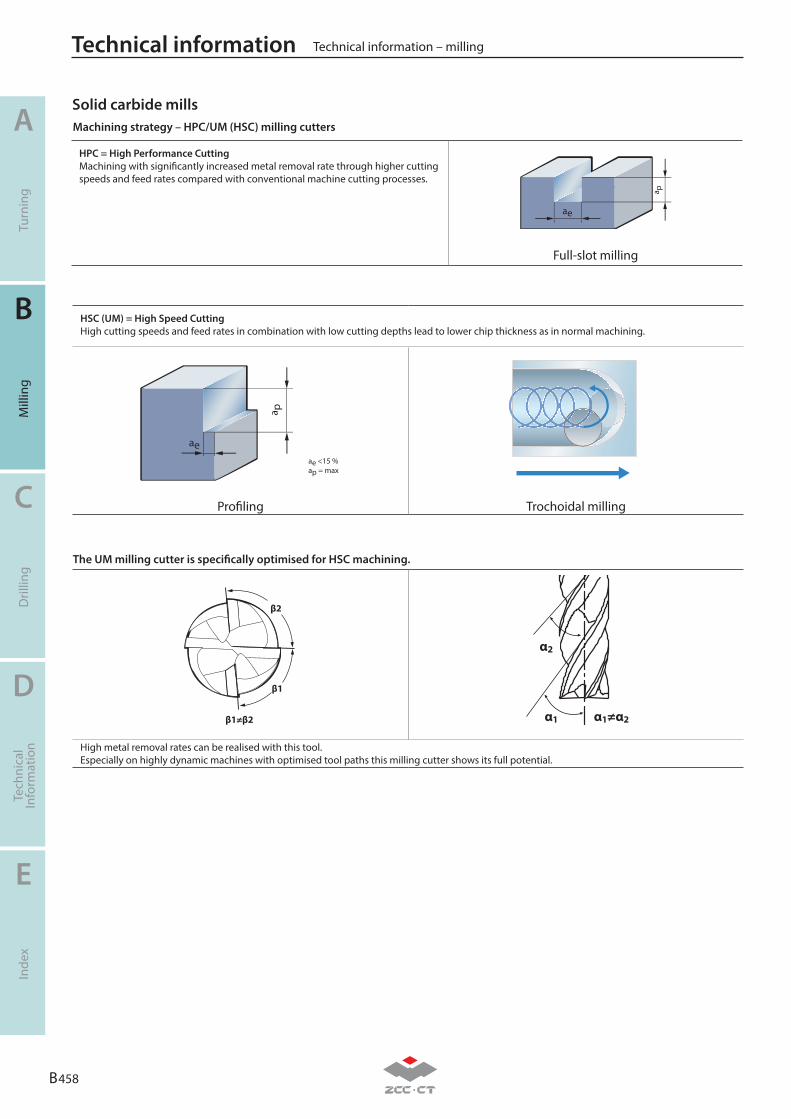
Solid carbide millsMachining strategy – HPC/UM (HSC) milling cutters
The UM milling cutter is specifically optimised for HSC machining.
HPC = High Performance CuttingMachining with significantly increased metal removal rate through higher cutting speeds and feed rates compared with conventional machine cutting processes.
ae
a p
Full-slot milling
HSC (UM) = High Speed CuttingHigh cutting speeds and feed rates in combination with low cutting depths lead to lower chip thickness as in normal machining.
ae
a p
ae <15 %ap = max
Profiling Trochoidal milling
β1
β2
β1≠β2
α2
α1 α1≠α2
High metal removal rates can be realised with this tool. Especially on highly dynamic machines with optimised tool paths this milling cutter shows its full potential.
B 458
A
B
C
D
E
Turn
ing
Mill
ing
Dril
ling
Tech
nica
lIn
form
atio
nIn
dex
Technical information – millingTechnical information
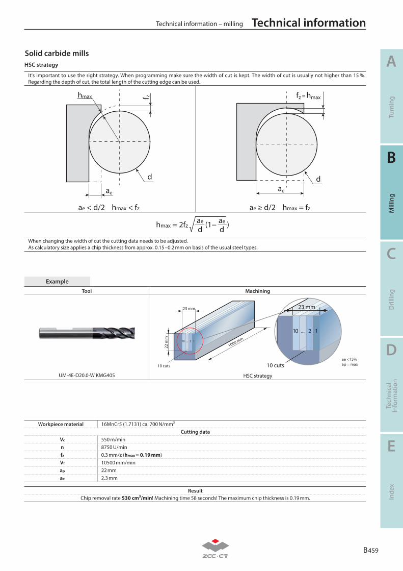
Workpiece material 16MnCr5 (1.7131) ca. 700 N/mm³Cutting data
Vc 550 m/minn 8750 U/minfz 0.3 mm/z (hmax = 0.19 mm)Vf 10500 mm/minap 22 mmae 2.3 mm
Tool Machining
1000 mm12...10
23 mm
22 m
m
12...10
10 cutsae <15%ap = max10 cuts
23 mm
UM-4E-D20.0-W KMG405 HSC strategy
Example
ResultChip removal rate 530 cm³/min! Machining time 58 seconds! The maximum chip thickness is 0.19 mm.
It's important to use the right strategy. When programming make sure the width of cut is kept. The width of cut is usually not higher than 15 %. Regarding the depth of cut, the total length of the cutting edge can be used.
ae
f zhmax
d dae
fz = hmax
ae < d/2 hmax < fz ae ≥ d/2 hmax = fz
hmax = 2fz (1− )ae ae
d dWhen changing the width of cut the cutting data needs to be adjusted. As calculatory size applies a chip thickness from approx. 0.15 –0.2 mm on basis of the usual steel types.
Solid carbide millsHSC strategy
B 459
A
B
C
D
E
Turn
ing
Mill
ing
Dril
ling
Tech
nica
lIn
form
atio
nIn
dex
Technical information – milling Technical information
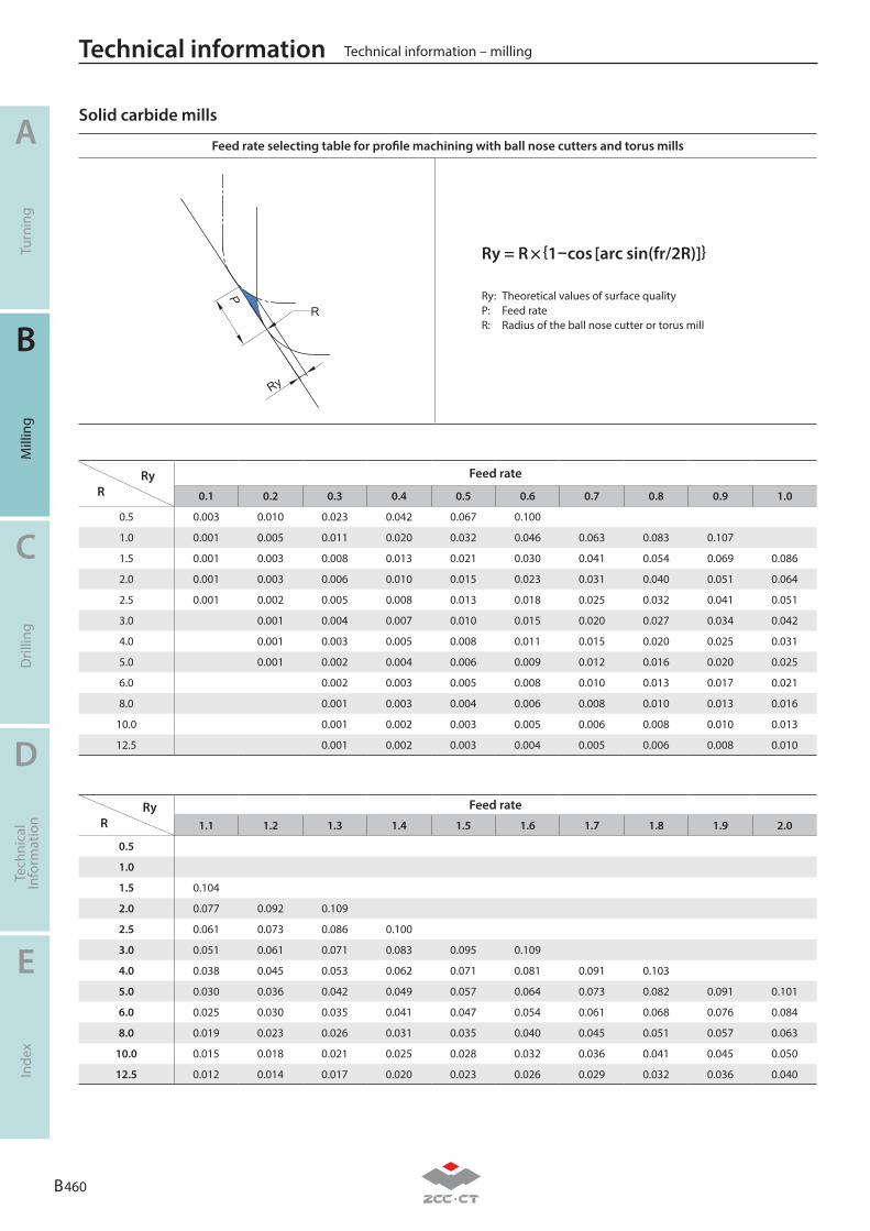
Ry R
Feed rate
0.1 0.2 0.3 0.4 0.5 0.6 0.7 0.8 0.9 1.0
0.5 0.003 0.010 0.023 0.042 0.067 0.100
1.0 0.001 0.005 0.011 0.020 0.032 0.046 0.063 0.083 0.107
1.5 0.001 0.003 0.008 0.013 0.021 0.030 0.041 0.054 0.069 0.086
2.0 0.001 0.003 0.006 0.010 0.015 0.023 0.031 0.040 0.051 0.064
2.5 0.001 0.002 0.005 0.008 0.013 0.018 0.025 0.032 0.041 0.051
3.0 0.001 0.004 0.007 0.010 0.015 0.020 0.027 0.034 0.042
4.0 0.001 0.003 0.005 0.008 0.011 0.015 0.020 0.025 0.031
5.0 0.001 0.002 0.004 0.006 0.009 0.012 0.016 0.020 0.025
6.0 0.002 0.003 0.005 0.008 0.010 0.013 0.017 0.021
8.0 0.001 0.003 0.004 0.006 0.008 0.010 0.013 0.016
10.0 0.001 0.002 0.003 0.005 0.006 0.008 0.010 0.013
12.5 0.001 0.002 0.003 0.004 0.005 0.006 0.008 0.010
Ry R
Feed rate
1.1 1.2 1.3 1.4 1.5 1.6 1.7 1.8 1.9 2.0
0.5
1.0
1.5 0.104
2.0 0.077 0.092 0.109
2.5 0.061 0.073 0.086 0.100
3.0 0.051 0.061 0.071 0.083 0.095 0.109
4.0 0.038 0.045 0.053 0.062 0.071 0.081 0.091 0.103
5.0 0.030 0.036 0.042 0.049 0.057 0.064 0.073 0.082 0.091 0.101
6.0 0.025 0.030 0.035 0.041 0.047 0.054 0.061 0.068 0.076 0.084
8.0 0.019 0.023 0.026 0.031 0.035 0.040 0.045 0.051 0.057 0.063
10.0 0.015 0.018 0.021 0.025 0.028 0.032 0.036 0.041 0.045 0.050
12.5 0.012 0.014 0.017 0.020 0.023 0.026 0.029 0.032 0.036 0.040
Feed rate selecting table for profile machining with ball nose cutters and torus mills
P
Ry = R × {1−cos [arc sin(fr/2R)]}
Ry: Theoretical values of surface qualityP: Feed rateR: Radius of the ball nose cutter or torus mill
Solid carbide mills
B 460
A
B
C
D
E
Turn
ing
Mill
ing
Dril
ling
Tech
nica
lIn
form
atio
nIn
dex
Technical information – millingTechnical information
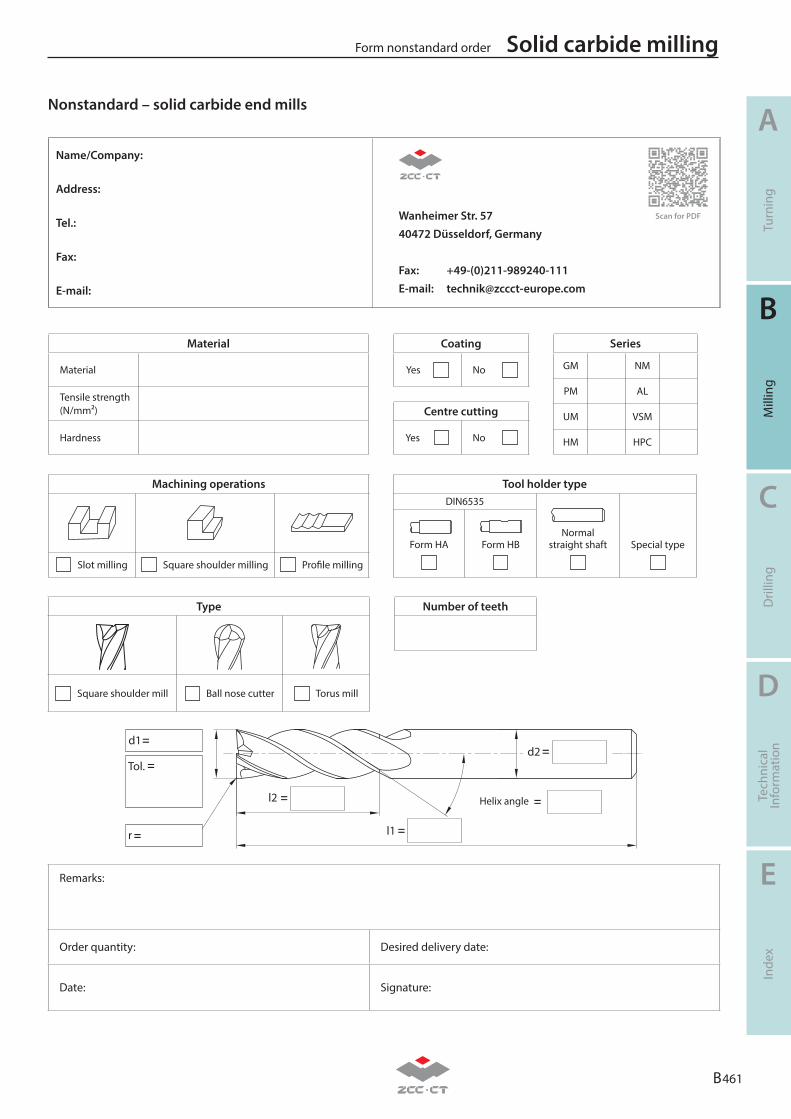
B 461
A
B
C
D
E
Turn
ing
Mill
ing
Dril
ling
Tech
nica
lIn
form
atio
nIn
dex
Solid carbide millingForm nonstandard order
Nonstandard – solid carbide end mills
Number of teethType
Square shoulder mill Ball nose cutter Torus mill
Tool holder typeDIN6535
Normal straight shaft Special type
Form HA Form HB
Machining operations
Slot milling Square shoulder milling Profile milling
Remarks:
Order quantity: Desired delivery date:
Date: Signature:
Series
GM NM
PM AL
UM VSM
HM HPC
Centre cutting
Yes No
Coating
Yes No
Material
Material
Tensile strength(N/mm²)
Hardness
=
=
=
Helix anglel2
l1
d2
=
d1
Tol.
=
=
r =
Name/Company:
Address:
Tel.: Wanheimer Str. 5740472 Düsseldorf, Germany
Fax: +49-(0)211-989240-111E-mail: [email protected]
Fax:
E-mail:
Scan for PDF
B 462
A
B
C
D
E
Turn
ing
Mill
ing
Dril
ling
Tech
nica
lIn
form
atio
nIn
dex
Solid carbide milling Form nonstandard order
Notes
D 1
A
B
C
D
E
Turn
ing
Mill
ing
Dril
ling
Tech
nica
lIn
form
atio
nIn
dex
Technical information
Comparison table materials D2-D8
Comparison table hardness and tensile strength D9-D10
Conversion table chip breaker – turning D11-D12
Conversion table chip breaker – milling/turning D13-D21
Example of materials for machining groups D22
Form test protocol D23
Torque for screw D24
D
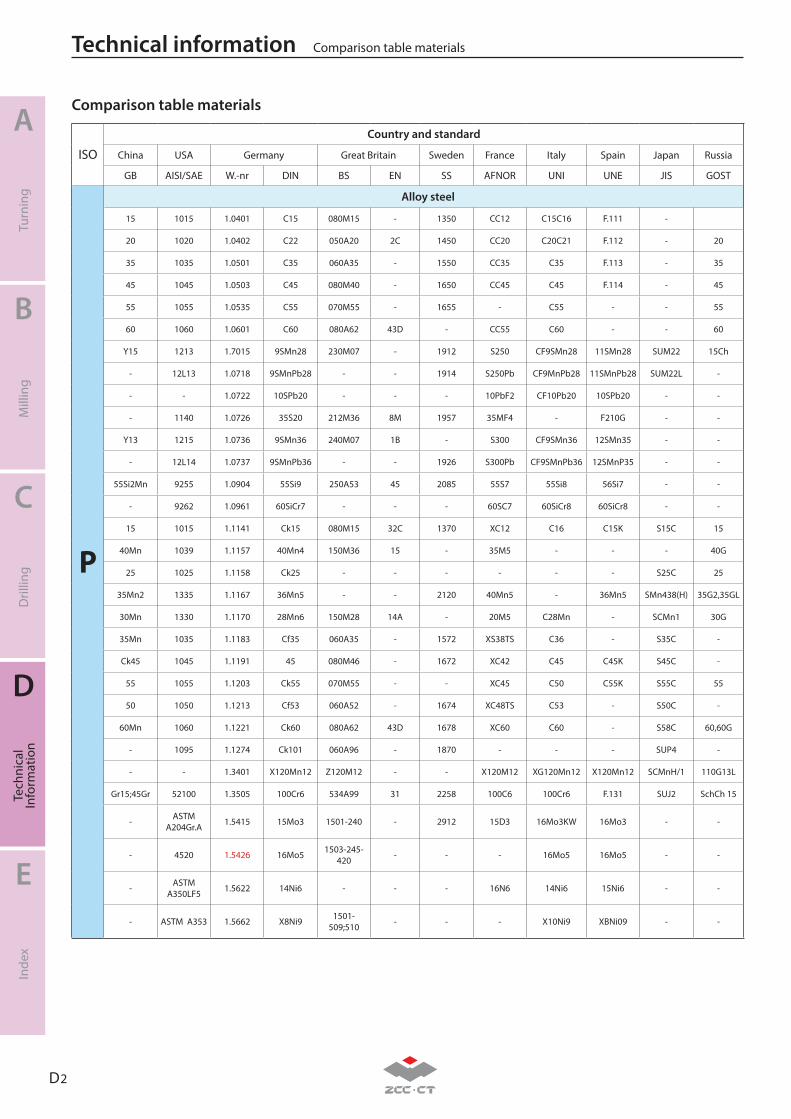
D 2
A
B
C
D
E
Turn
ing
Mill
ing
Dril
ling
Tech
nica
lIn
form
atio
nIn
dex
Technical information Comparison table materials
ISO
Country and standard
China USA Germany Great Britain Sweden France Italy Spain Japan Russia
GB AISI/SAE W.-nr DIN BS EN SS AFNOR UNI UNE JIS GOST
P
Alloy steel
15 1015 1.0401 C15 080M15 - 1350 CC12 C15C16 F.111 -
20 1020 1.0402 C22 050A20 2C 1450 CC20 C20C21 F.112 - 20
35 1035 1.0501 C35 060A35 - 1550 CC35 C35 F.113 - 35
45 1045 1.0503 C45 080M40 - 1650 CC45 C45 F.114 - 45
55 1055 1.0535 C55 070M55 - 1655 - C55 - - 55
60 1060 1.0601 C60 080A62 43D - CC55 C60 - - 60
Y15 1213 1.7015 9SMn28 230M07 - 1912 S250 CF9SMn28 11SMn28 SUM22 15Ch
- 12L13 1.0718 9SMnPb28 - - 1914 S250Pb CF9MnPb28 11SMnPb28 SUM22L -
- - 1.0722 10SPb20 - - - 10PbF2 CF10Pb20 10SPb20 - -
- 1140 1.0726 35S20 212M36 8M 1957 35MF4 - F210G - -
Y13 1215 1.0736 9SMn36 240M07 1B - S300 CF9SMn36 12SMn35 - -
- 12L14 1.0737 9SMnPb36 - - 1926 S300Pb CF9SMnPb36 12SMnP35 - -
55Si2Mn 9255 1.0904 55Si9 250A53 45 2085 55S7 55Si8 56Si7 - -
- 9262 1.0961 60SiCr7 - - - 60SC7 60SiCr8 60SiCr8 - -
15 1015 1.1141 Ck15 080M15 32C 1370 XC12 C16 C15K S15C 15
40Mn 1039 1.1157 40Mn4 150M36 15 - 35M5 - - - 40G
25 1025 1.1158 Ck25 - - - - - - S25C 25
35Mn2 1335 1.1167 36Mn5 - - 2120 40Mn5 - 36Mn5 SMn438(H) 35G2,35GL
30Mn 1330 1.1170 28Mn6 150M28 14A - 20M5 C28Mn - SCMn1 30G
35Mn 1035 1.1183 Cf35 060A35 - 1572 XS38TS C36 - S35C -
Ck45 1045 1.1191 45 080M46 - 1672 XC42 C45 C45K S45C -
55 1055 1.1203 Ck55 070M55 - - XC45 C50 C55K S55C 55
50 1050 1.1213 Cf53 060A52 - 1674 XC48TS C53 - S50C -
60Mn 1060 1.1221 Ck60 080A62 43D 1678 XC60 C60 - S58C 60,60G
- 1095 1.1274 Ck101 060A96 - 1870 - - - SUP4 -
- - 1.3401 X120Mn12 Z120M12 - - X120M12 XG120Mn12 X120Mn12 SCMnH/1 110G13L
Gr15;45Gr 52100 1.3505 100Cr6 534A99 31 2258 100C6 100Cr6 F.131 SUJ2 SchCh 15
- ASTM A204Gr.A 1.5415 15Mo3 1501-240 - 2912 15D3 16Mo3KW 16Mo3 - -
- 4520 1.5426 16Mo5 1503-245-420 - - - 16Mo5 16Mo5 - -
- ASTM A350LF5 1.5622 14Ni6 - - - 16N6 14Ni6 15Ni6 - -
- ASTM A353 1.5662 X8Ni9 1501-509;510 - - - X10Ni9 XBNi09 - -
Comparison table materials
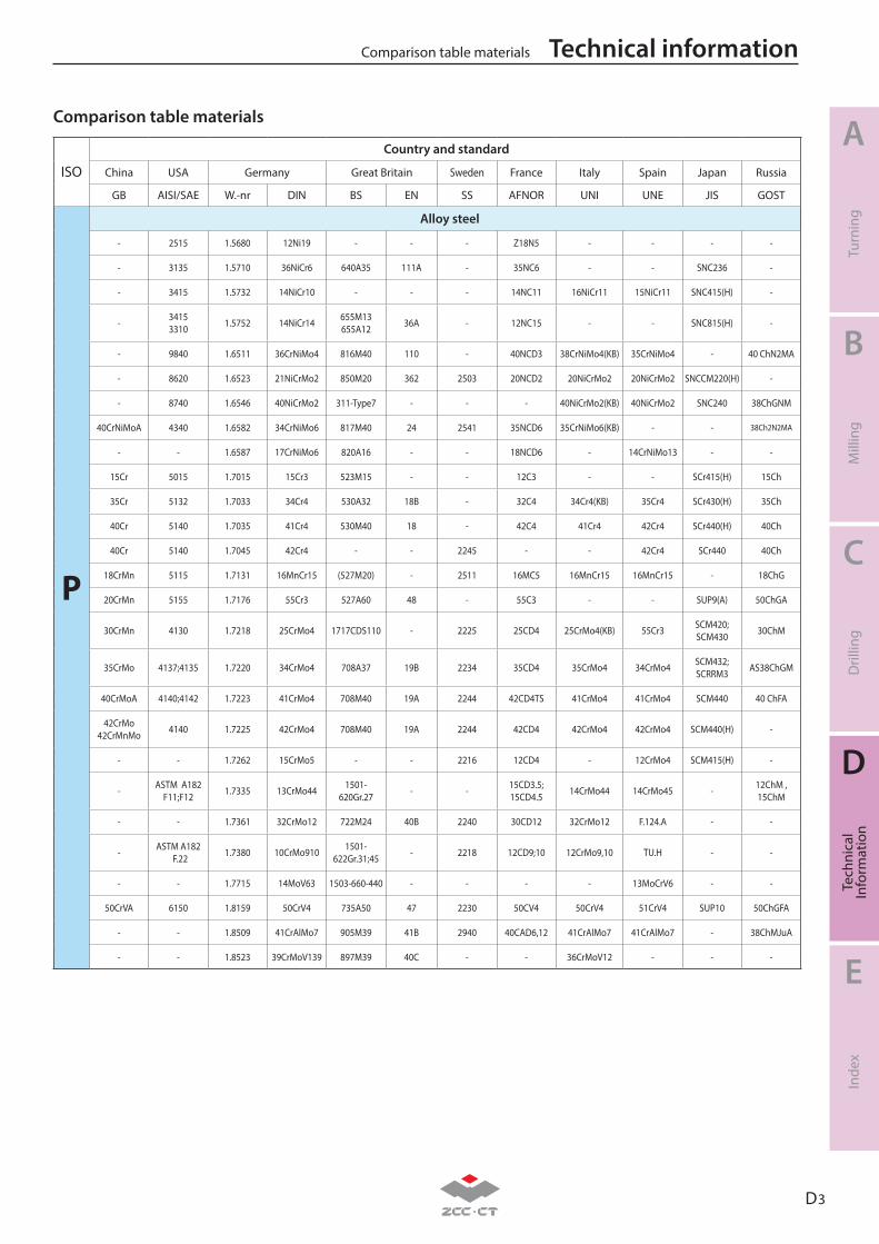
D 3
A
B
C
D
E
Turn
ing
Mill
ing
Dril
ling
Tech
nica
lIn
form
atio
nIn
dex
Technical informationComparison table materials
ISO
Country and standard
China USA Germany Great Britain Sweden France Italy Spain Japan Russia
GB AISI/SAE W.-nr DIN BS EN SS AFNOR UNI UNE JIS GOST
P
Alloy steel
- 2515 1.5680 12Ni19 - - - Z18N5 - - - -
- 3135 1.5710 36NiCr6 640A35 111A - 35NC6 - - SNC236 -
- 3415 1.5732 14NiCr10 - - - 14NC11 16NiCr11 15NiCr11 SNC415(H) -
- 34153310 1.5752 14NiCr14 655M13
655A12 36A - 12NC15 - - SNC815(H) -
- 9840 1.6511 36CrNiMo4 816M40 110 - 40NCD3 38CrNiMo4(KB) 35CrNiMo4 - 40 ChN2MA
- 8620 1.6523 21NiCrMo2 850M20 362 2503 20NCD2 20NiCrMo2 20NiCrMo2 SNCCM220(H) -
- 8740 1.6546 40NiCrMo2 311-Type7 - - - 40NiCrMo2(KB) 40NiCrMo2 SNC240 38ChGNM
40CrNiMoA 4340 1.6582 34CrNiMo6 817M40 24 2541 35NCD6 35CrNiMo6(KB) - - 38Ch2N2MA
- - 1.6587 17CrNiMo6 820A16 - - 18NCD6 - 14CrNiMo13 - -
15Cr 5015 1.7015 15Cr3 523M15 - - 12C3 - - SCr415(H) 15Ch
35Cr 5132 1.7033 34Cr4 530A32 18B - 32C4 34Cr4(KB) 35Cr4 SCr430(H) 35Ch
40Cr 5140 1.7035 41Cr4 530M40 18 - 42C4 41Cr4 42Cr4 SCr440(H) 40Ch
40Cr 5140 1.7045 42Cr4 - - 2245 - - 42Cr4 SCr440 40Ch
18CrMn 5115 1.7131 16MnCr15 (527M20) - 2511 16MC5 16MnCr15 16MnCr15 - 18ChG
20CrMn 5155 1.7176 55Cr3 527A60 48 - 55C3 - - SUP9(A) 50ChGA
30CrMn 4130 1.7218 25CrMo4 1717CDS110 - 2225 25CD4 25CrMo4(KB) 55Cr3 SCM420;SCM430 30ChM
35CrMo 4137;4135 1.7220 34CrMo4 708A37 19B 2234 35CD4 35CrMo4 34CrMo4 SCM432;SCRRM3 AS38ChGM
40CrMoA 4140;4142 1.7223 41CrMo4 708M40 19A 2244 42CD4TS 41CrMo4 41CrMo4 SCM440 40 ChFA
42CrMo42CrMnMo 4140 1.7225 42CrMo4 708M40 19A 2244 42CD4 42CrMo4 42CrMo4 SCM440(H) -
- - 1.7262 15CrMo5 - - 2216 12CD4 - 12CrMo4 SCM415(H) -
- ASTM A182F11;F12 1.7335 13CrMo44 1501-
620Gr.27 - - 15CD3.5;15CD4.5 14CrMo44 14CrMo45 - 12ChM ,
15ChM
- - 1.7361 32CrMo12 722M24 40B 2240 30CD12 32CrMo12 F.124.A - -
- ASTM A182 F.22 1.7380 10CrMo910 1501-
622Gr.31;45 - 2218 12CD9;10 12CrMo9,10 TU.H - -
- - 1.7715 14MoV63 1503-660-440 - - - - 13MoCrV6 - -
50CrVA 6150 1.8159 50CrV4 735A50 47 2230 50CV4 50CrV4 51CrV4 SUP10 50ChGFA
- - 1.8509 41CrAlMo7 905M39 41B 2940 40CAD6,12 41CrAlMo7 41CrAlMo7 - 38ChMJuA
- - 1.8523 39CrMoV139 897M39 40C - - 36CrMoV12 - - -
Comparison table materials
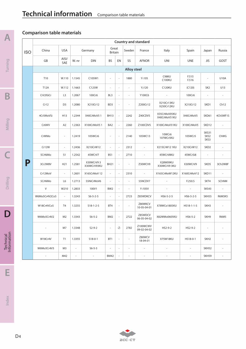
D 4
A
B
C
D
E
Turn
ing
Mill
ing
Dril
ling
Tech
nica
lIn
form
atio
nIn
dex
Technical information Comparison table materials
ISO
Country and standard
China USA Germany Great Britain Sweden France Italy Spain Japan Russia
GB AISI/SAE W.-nr DIN BS EN SS AFNOR UNI UNE JIS GOST
P
Alloy steel
T10 W.110 1.1545 C105W1 - - 1880 Y1105 C98KUC100KU
F.515F.516 - U10A
T12A W.112 1.1663 C125W - - - Y2120 C120KU (C120) SK2 U13
CrV;9SiCr L3 1.2067 100Cr6 BL3 - - Y100C6 - 100Cr6 - -
Cr12 D3 1.2080 X210Cr12 BD3 - - Z200Cr12 X210Cr13KUX250Cr12KU X210Cr12 SKD1 Ch12
4Cr5MoVSi H13 1.2344 X40CrMoV5 1 BH13 - 2242 Z40CDV5 X35CrMoV05KUX40CrMoV51KU X40CrMoV5 SKD61 4Ch5MF1S
Cr6WV A2 1.2363 X100CrMoV5 1 BA2 - 2260 Z100CDV5 X100CrMoV51KU X100CrMoV5 SKD12 -
CrWMo - 1.2419 105WCr6 - - 2140 105WC13 10WCr6107WCr5KU 105WCr5
SKS31SKS2SKS3
ChWG
Cr12W - 1.2436 X210CrW12 - - 2312 - X215CrW12 1KU X210CrW12 SKD2 -
5CrNiMo S1 1.2542 45WCrV7 BS1 - 2710 - 45WCrV8KU 45WCrSi8 - -
3Cr2W8V H21 1.2581 X30WCrV9 3X30WCrV93KU BH21 - - Z30WCV9 X28W09KU
X30WCrV9 3KU X30WCrV9 SKD5 3Ch2W8F
Cr12MoV - 1.2601 X165CrMoV 12 - - 2310 - X165CrMoW12KU X160CrMoV12 SKD11 -
5CrNiMo L6 1.2713 55NiCrMoV6 - - - 55NCDV7 - F.250.S SKT4 5ChNM
V W210 1.2833 100V1 BW2 - - Y1105V - - SKS43 -
W6Mo5Cr4V2Co5 - 1.3243 S6-5-2-5 - - 2723 Z85WDKCV HS6-5-2-5 HS6-5-2-5 SKH55 R6M5K5
W18Cr4VCo5 T4 1.3255 S18-1-2-5 BT4 - - Z80WKCV10-05-04-01 X78WCo1805KU HS18-1-1-5 SKH3 -
W6Mo5Cr4V2 M2 1.3343 S6-5-2 BM2 - 2722 Z85WDCV06-05-04-02 X82WMo0605KU HS6-5-2 SKH9 R6M5
- M7 1.3348 S2-9-2 - -Z- 2782 Z100WCWV09-02-04-02 HS2-9-2 HS2-9-2 - -
W18Cr4V T1 1.3355 S18-0-1 BT1 - - Z80WCV18-04-01 X75W18KU HS18-0-1 SKH2 -
W6Mo5Cr4V3 M3 - S6-5-3 - - - - - - SKH52 -
- M42 - - BM42 - - - - - SKH59 -
Comparison table materials
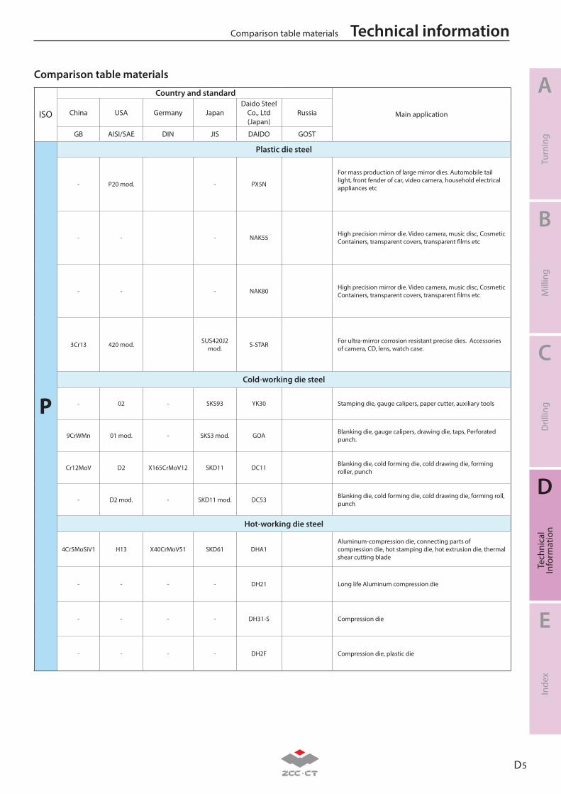
D 5
A
B
C
D
E
Turn
ing
Mill
ing
Dril
ling
Tech
nica
lIn
form
atio
nIn
dex
Technical informationComparison table materials
ISO
Country and standard
Main applicationChina USA Germany JapanDaido Steel
Co., Ltd (Japan)
Russia
GB AISI/SAE DIN JIS DAIDO GOST
P
Plastic die steel
- P20 mod. - PX5N
For mass production of large mirror dies. Automobile tail light, front fender of car, video camera, household electrical appliances etc
- - - NAK55 High precision mirror die. Video camera, music disc, Cosmetic Containers, transparent covers, transparent films etc
- - - NAK80 High precision mirror die. Video camera, music disc, Cosmetic Containers, transparent covers, transparent films etc
3Cr13 420 mod. SUS420J2 mod. S-STAR For ultra-mirror corrosion resistant precise dies. Accessories
of camera, CD, lens, watch case.
Cold-working die steel
- 02 - SKS93 YK30 Stamping die, gauge calipers, paper cutter, auxiliary tools
9CrWMn 01 mod. - SKS3 mod. GOA Blanking die, gauge calipers, drawing die, taps, Perforated punch.
Cr12MoV D2 X165CrMoV12 SKD11 DC11 Blanking die, cold forming die, cold drawing die, forming roller, punch
- D2 mod. - SKD11 mod. DC53 Blanking die, cold forming die, cold drawing die, forming roll, punch
Hot-working die steel
4Cr5MoSiV1 H13 X40CrMoV51 SKD61 DHA1Aluminum-compression die, connecting parts of compression die, hot stamping die, hot extrusion die, thermal shear cutting blade
- - - - DH21 Long life Aluminum compression die
- - - - DH31-S Compression die
- - - - DH2F Compression die, plastic die
Comparison table materials
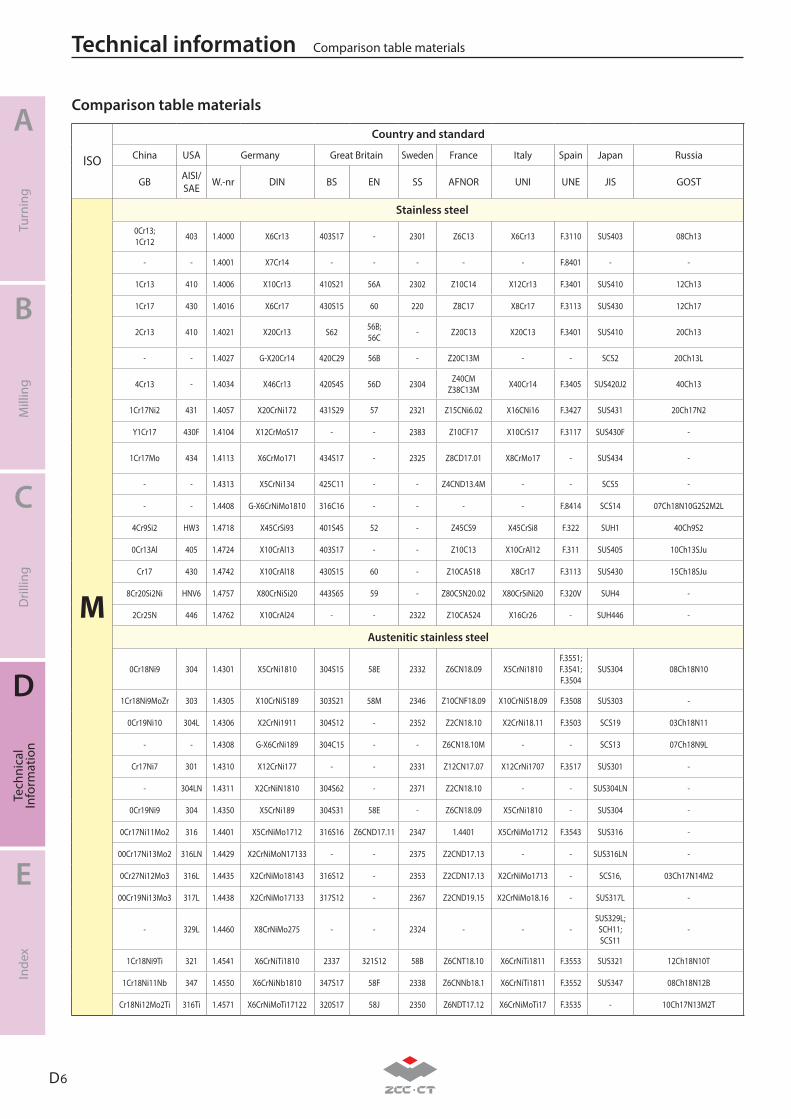
D 6
A
B
C
D
E
Turn
ing
Mill
ing
Dril
ling
Tech
nica
lIn
form
atio
nIn
dex
Technical information Comparison table materials
ISO
Country and standard
China USA Germany Great Britain Sweden France Italy Spain Japan Russia
GB AISI/SAE W.-nr DIN BS EN SS AFNOR UNI UNE JIS GOST
M
Stainless steel
0Cr13;1Cr12 403 1.4000 X6Cr13 403S17 - 2301 Z6C13 X6Cr13 F.3110 SUS403 08Ch13
- - 1.4001 X7Cr14 - - - - - F.8401 - -
1Cr13 410 1.4006 X10Cr13 410S21 56A 2302 Z10C14 X12Cr13 F.3401 SUS410 12Ch13
1Cr17 430 1.4016 X6Cr17 430S15 60 220 Z8C17 X8Cr17 F.3113 SUS430 12Ch17
2Cr13 410 1.4021 X20Cr13 S62 56B;56C - Z20C13 X20C13 F.3401 SUS410 20Ch13
- - 1.4027 G-X20Cr14 420C29 56B - Z20C13M - - SCS2 20Ch13L
4Cr13 - 1.4034 X46Cr13 420S45 56D 2304 Z40CMZ38C13M X40Cr14 F.3405 SUS420J2 40Ch13
1Cr17Ni2 431 1.4057 X20CrNi172 431S29 57 2321 Z15CNi6.02 X16CNi16 F.3427 SUS431 20Ch17N2
Y1Cr17 430F 1.4104 X12CrMoS17 - - 2383 Z10CF17 X10CrS17 F.3117 SUS430F -
1Cr17Mo 434 1.4113 X6CrMo171 434S17 - 2325 Z8CD17.01 X8CrMo17 - SUS434 -
- - 1.4313 X5CrNi134 425C11 - - Z4CND13.4M - - SCS5 -
- - 1.4408 G-X6CrNiMo1810 316C16 - - - - F.8414 SCS14 07Ch18N10G2S2M2L
4Cr9Si2 HW3 1.4718 X45CrSi93 401S45 52 - Z45CS9 X45CrSi8 F.322 SUH1 40Ch9S2
0Cr13Al 405 1.4724 X10CrAl13 403S17 - - Z10C13 X10CrAl12 F.311 SUS405 10Ch13SJu
Cr17 430 1.4742 X10CrAl18 430S15 60 - Z10CAS18 X8Cr17 F.3113 SUS430 15Ch18SJu
8Cr20Si2Ni HNV6 1.4757 X80CrNiSi20 443S65 59 - Z80CSN20.02 X80CrSiNi20 F.320V SUH4 -
2Cr25N 446 1.4762 X10CrAl24 - - 2322 Z10CAS24 X16Cr26 - SUH446 -
Austenitic stainless steel
0Cr18Ni9 304 1.4301 X5CrNi1810 304S15 58E 2332 Z6CN18.09 X5CrNi1810 F.3551;F.3541;F.3504
SUS304 08Ch18N10
1Cr18Ni9MoZr 303 1.4305 X10CrNiS189 303S21 58M 2346 Z10CNF18.09 X10CrNiS18.09 F.3508 SUS303 -
0Cr19Ni10 304L 1.4306 X2CrNi1911 304S12 - 2352 Z2CN18.10 X2CrNi18.11 F.3503 SCS19 03Ch18N11
- - 1.4308 G-X6CrNi189 304C15 - - Z6CN18.10M - - SCS13 07Ch18N9L
Cr17Ni7 301 1.4310 X12CrNi177 - - 2331 Z12CN17.07 X12CrNi1707 F.3517 SUS301 -
- 304LN 1.4311 X2CrNiN1810 304S62 - 2371 Z2CN18.10 - - SUS304LN -
0Cr19Ni9 304 1.4350 X5CrNi189 304S31 58E - Z6CN18.09 X5CrNi1810 - SUS304 -
0Cr17Ni11Mo2 316 1.4401 X5CrNiMo1712 316S16 Z6CND17.11 2347 1.4401 X5CrNiMo1712 F.3543 SUS316 -
00Cr17Ni13Mo2 316LN 1.4429 X2CrNiMoN17133 - - 2375 Z2CND17.13 - - SUS316LN -
0Cr27Ni12Mo3 316L 1.4435 X2CrNiMo18143 316S12 - 2353 Z2CDN17.13 X2CrNiMo1713 - SCS16, 03Ch17N14M2
00Cr19Ni13Mo3 317L 1.4438 X2CrNiMo17133 317S12 - 2367 Z2CND19.15 X2CrNiMo18.16 - SUS317L -
- 329L 1.4460 X8CrNiMo275 - - 2324 - - - SUS329L;
SCH11;SCS11
-
1Cr18Ni9Ti 321 1.4541 X6CrNiTi1810 2337 321S12 58B Z6CNT18.10 X6CrNiTi1811 F.3553 SUS321 12Ch18N10T
1Cr18Ni11Nb 347 1.4550 X6CrNiNb1810 347S17 58F 2338 Z6CNNb18.1 X6CrNiTi1811 F.3552 SUS347 08Ch18N12B
Cr18Ni12Mo2Ti 316Ti 1.4571 X6CrNiMoTi17122 320S17 58J 2350 Z6NDT17.12 X6CrNiMoTi17 F.3535 - 10Ch17N13M2T
Comparison table materials
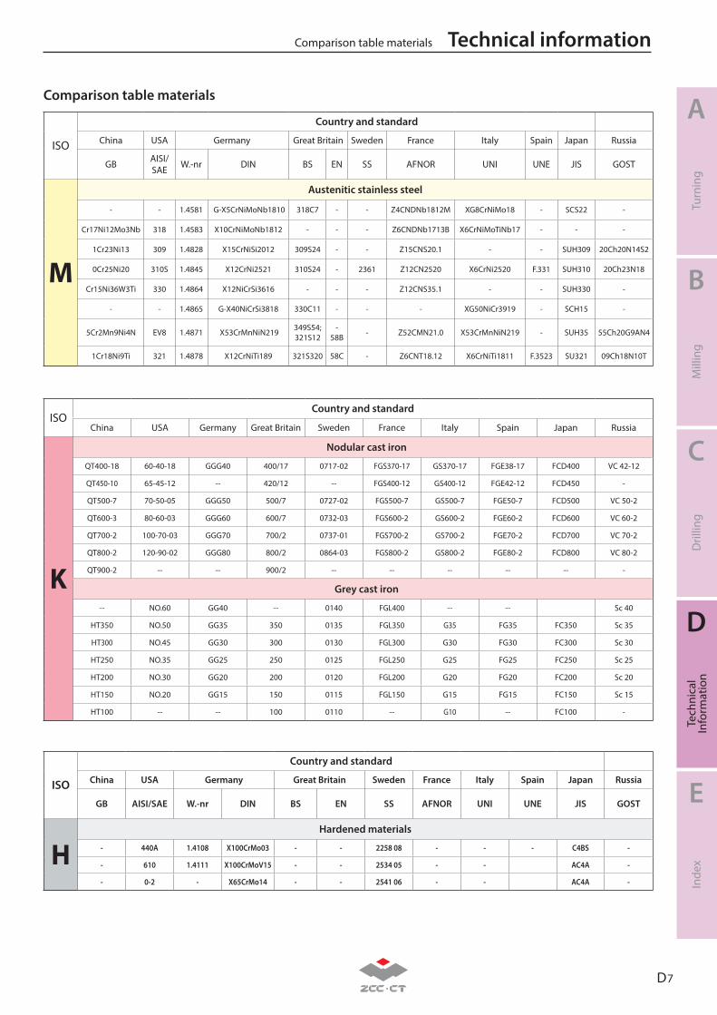
D 7
A
B
C
D
E
Turn
ing
Mill
ing
Dril
ling
Tech
nica
lIn
form
atio
nIn
dex
Technical informationComparison table materials
ISO
Country and standard
China USA Germany Great Britain Sweden France Italy Spain Japan Russia
GB AISI/SAE W.-nr DIN BS EN SS AFNOR UNI UNE JIS GOST
M
Austenitic stainless steel
- - 1.4581 G-X5CrNiMoNb1810 318C7 - - Z4CNDNb1812M XG8CrNiMo18 - SCS22 -
Cr17Ni12Mo3Nb 318 1.4583 X10CrNiMoNb1812 - - - Z6CNDNb1713B X6CrNiMoTiNb17 - - -
1Cr23Ni13 309 1.4828 X15CrNiSi2012 309S24 - - Z15CNS20.1 - - SUH309 20Ch20N14S2
0Cr25Ni20 310S 1.4845 X12CrNi2521 310S24 - 2361 Z12CN2520 X6CrNi2520 F.331 SUH310 20Ch23N18
Cr15Ni36W3Ti 330 1.4864 X12NiCrSi3616 - - - Z12CNS35.1 - - SUH330 -
- - 1.4865 G-X40NiCrSi3818 330C11 - - - XG50NiCr3919 - SCH15 -
5Cr2Mn9Ni4N EV8 1.4871 X53CrMnNiN219 349S54;321S12
-58B - Z52CMN21.0 X53CrMnNiN219 - SUH35 55Ch20G9AN4
1Cr18Ni9Ti 321 1.4878 X12CrNiTi189 321S320 58C - Z6CNT18.12 X6CrNiTi1811 F.3523 SU321 09Ch18N10T
ISOCountry and standard
China USA Germany Great Britain Sweden France Italy Spain Japan Russia
K
Nodular cast iron
QT400-18 60-40-18 GGG40 400/17 0717-02 FGS370-17 GS370-17 FGE38-17 FCD400 VC 42-12
QT450-10 65-45-12 -- 420/12 -- FGS400-12 GS400-12 FGE42-12 FCD450 -
QT500-7 70-50-05 GGG50 500/7 0727-02 FGS500-7 GS500-7 FGE50-7 FCD500 VC 50-2
QT600-3 80-60-03 GGG60 600/7 0732-03 FGS600-2 GS600-2 FGE60-2 FCD600 VC 60-2
QT700-2 100-70-03 GGG70 700/2 0737-01 FGS700-2 GS700-2 FGE70-2 FCD700 VC 70-2
QT800-2 120-90-02 GGG80 800/2 0864-03 FGS800-2 GS800-2 FGE80-2 FCD800 VC 80-2
QT900-2 -- -- 900/2 -- -- -- -- -- -
Grey cast iron
-- NO.60 GG40 -- 0140 FGL400 -- -- Sc 40
HT350 NO.50 GG35 350 0135 FGL350 G35 FG35 FC350 Sc 35
HT300 NO.45 GG30 300 0130 FGL300 G30 FG30 FC300 Sc 30
HT250 NO.35 GG25 250 0125 FGL250 G25 FG25 FC250 Sc 25
HT200 NO.30 GG20 200 0120 FGL200 G20 FG20 FC200 Sc 20
HT150 NO.20 GG15 150 0115 FGL150 G15 FG15 FC150 Sc 15
HT100 -- -- 100 0110 -- G10 -- FC100 -
ISO
Country and standard
China USA Germany Great Britain Sweden France Italy Spain Japan Russia
GB AISI/SAE W.-nr DIN BS EN SS AFNOR UNI UNE JIS GOST
HHardened materials
- 440A 1.4108 X100CrMo03 - - 2258 08 - - - C4BS -
- 610 1.4111 X100CrMoV15 - - 2534 05 - - AC4A -
- 0-2 - X65CrMo14 - - 2541 06 - - AC4A -
Comparison table materials
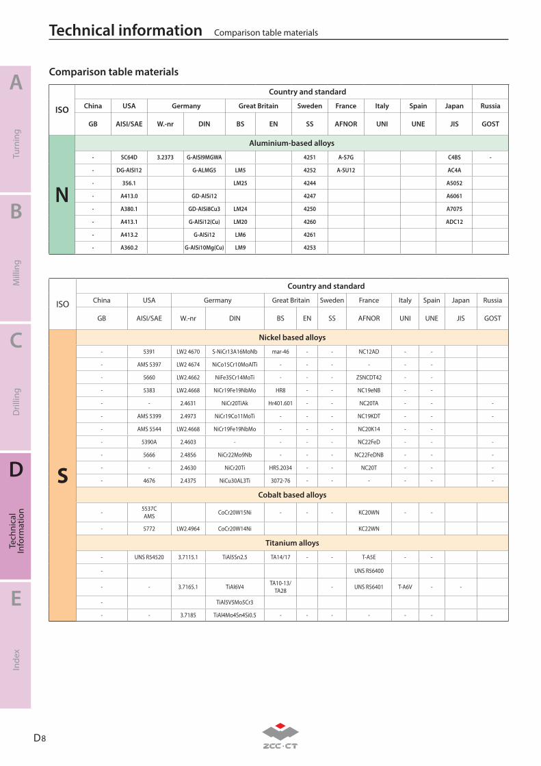
D 8
A
B
C
D
E
Turn
ing
Mill
ing
Dril
ling
Tech
nica
lIn
form
atio
nIn
dex
Technical information Comparison table materials
ISO
Country and standard
China USA Germany Great Britain Sweden France Italy Spain Japan Russia
GB AISI/SAE W.-nr DIN BS EN SS AFNOR UNI UNE JIS GOST
N
Aluminium-based alloys
- SC64D 3.2373 G-AISI9MGWA 4251 A-S7G C4BS -
- DG-AISI12 G-ALMG5 LM5 4252 A-SU12 AC4A
- 356.1 LM25 4244 A5052
- A413.0 GD-AISi12 4247 A6061
- A380.1 GD-AISi8Cu3 LM24 4250 A7075
- A413.1 G-AISi12(Cu) LM20 4260 ADC12
- A413.2 G-AISi12 LM6 4261
- A360.2 G-AISi10Mg(Cu) LM9 4253
ISO
Country and standard
China USA Germany Great Britain Sweden France Italy Spain Japan Russia
GB AISI/SAE W.-nr DIN BS EN SS AFNOR UNI UNE JIS GOST
S
Nickel based alloys
- 5391 LW2 4670 S-NiCr13A16MoNb mar-46 - - NC12AD - -
- AMS 5397 LW2 4674 NiCo15Cr10MoAlTi - - - - - -
- 5660 LW2.4662 NiFe35Cr14MoTi - - - ZSNCDT42 - -
- 5383 LW2.4668 NiCr19Fe19NbMo HR8 - - NC19eNB - -
- - 2.4631 NiCr20TiAk Hr401.601 - - NC20TA - - -
- AMS 5399 2.4973 NiCr19Co11MoTi - - - NC19KDT - - -
- AMS 5544 LW2.4668 NiCr19Fe19NbMo - - - NC20K14 - -
- 5390A 2.4603 - - - - NC22FeD - - -
- 5666 2.4856 NiCr22Mo9Nb - - - NC22FeDNB - - -
- - 2.4630 NiCr20Ti HR5.2034 - - NC20T - - -
- 4676 2.4375 NiCu30AL3Ti 3072-76 - - - - - -
Cobalt based alloys
- 5537CAMS CoCr20W15Ni - - - KC20WN - -
- 5772 LW2.4964 CoCr20W14Ni KC22WN
Titanium alloys
- UNS R54520 3.7115.1 TiAl5Sn2.5 TA14/17 - - T-A5E - -
- UNS R56400
- - 3.7165.1 TiAl6V4 TA10-13/TA28 - UNS R56401 T-A6V - -
- TiAl5V5Mo5Cr3
- - 3.7185 TiAl4Mo4Sn4Si0.5 - - - - - -
Comparison table materials
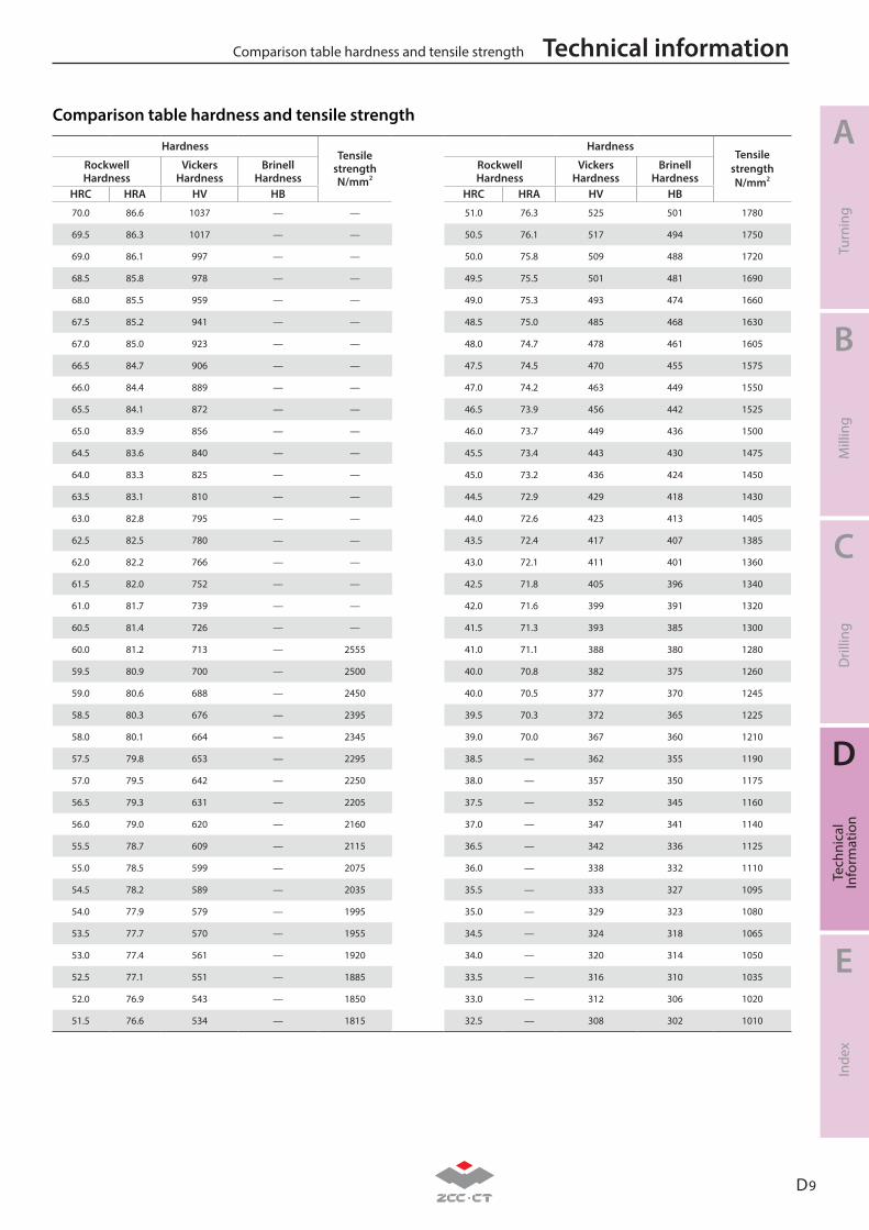
D 9
A
B
C
D
E
Turn
ing
Mill
ing
Dril
ling
Tech
nica
lIn
form
atio
nIn
dex
Technical informationComparison table hardness and tensile strength
HardnessTensile
strengthN/mm2
HardnessTensile
strengthN/mm2
Rockwell Hardness
VickersHardness
BrinellHardness
Rockwell Hardness
VickersHardness
BrinellHardness
HRC HRA HV HB HRC HRA HV HB
70.0 86.6 1037 — — 51.0 76.3 525 501 1780
69.5 86.3 1017 — — 50.5 76.1 517 494 1750
69.0 86.1 997 — — 50.0 75.8 509 488 1720
68.5 85.8 978 — — 49.5 75.5 501 481 1690
68.0 85.5 959 — — 49.0 75.3 493 474 1660
67.5 85.2 941 — — 48.5 75.0 485 468 1630
67.0 85.0 923 — — 48.0 74.7 478 461 1605
66.5 84.7 906 — — 47.5 74.5 470 455 1575
66.0 84.4 889 — — 47.0 74.2 463 449 1550
65.5 84.1 872 — — 46.5 73.9 456 442 1525
65.0 83.9 856 — — 46.0 73.7 449 436 1500
64.5 83.6 840 — — 45.5 73.4 443 430 1475
64.0 83.3 825 — — 45.0 73.2 436 424 1450
63.5 83.1 810 — — 44.5 72.9 429 418 1430
63.0 82.8 795 — — 44.0 72.6 423 413 1405
62.5 82.5 780 — — 43.5 72.4 417 407 1385
62.0 82.2 766 — — 43.0 72.1 411 401 1360
61.5 82.0 752 — — 42.5 71.8 405 396 1340
61.0 81.7 739 — — 42.0 71.6 399 391 1320
60.5 81.4 726 — — 41.5 71.3 393 385 1300
60.0 81.2 713 — 2555 41.0 71.1 388 380 1280
59.5 80.9 700 — 2500 40.0 70.8 382 375 1260
59.0 80.6 688 — 2450 40.0 70.5 377 370 1245
58.5 80.3 676 — 2395 39.5 70.3 372 365 1225
58.0 80.1 664 — 2345 39.0 70.0 367 360 1210
57.5 79.8 653 — 2295 38.5 — 362 355 1190
57.0 79.5 642 — 2250 38.0 — 357 350 1175
56.5 79.3 631 — 2205 37.5 — 352 345 1160
56.0 79.0 620 — 2160 37.0 — 347 341 1140
55.5 78.7 609 — 2115 36.5 — 342 336 1125
55.0 78.5 599 — 2075 36.0 — 338 332 1110
54.5 78.2 589 — 2035 35.5 — 333 327 1095
54.0 77.9 579 — 1995 35.0 — 329 323 1080
53.5 77.7 570 — 1955 34.5 — 324 318 1065
53.0 77.4 561 — 1920 34.0 — 320 314 1050
52.5 77.1 551 — 1885 33.5 — 316 310 1035
52.0 76.9 543 — 1850 33.0 — 312 306 1020
51.5 76.6 534 — 1815 32.5 — 308 302 1010
Comparison table hardness and tensile strength

D 10
A
B
C
D
E
Turn
ing
Mill
ing
Dril
ling
Tech
nica
lIn
form
atio
nIn
dex
Technical information Comparison table hardness and tensile strength
HardnessTensile
strengthN/mm2
HardnessTensile
strengthN/mm2
Rockwell Hardness
VickersHardness
BrinellHardness
Rockwell Hardness
VickersHardness
BrinellHardness
HRC HRA HV HB HRC HRA HV HB
32.0 — 304 298 995 24.0 — 249 245 820
31.5 — 300 294 980 23.5 — 246 242 810
31.0 — 296 291 970 23.0 — 243 240 800
30.5 — 292 287 960 22.5 — 240 237 790
30.0 — 289 283 950 22.0 — 237 234 785
29.5 — 285 280 935 21.5 — 234 232 775
29.0 — 281 276 920 21.0 — 231 229 765
28.5 — 278 273 910 20.5 — 229 227 760
28.0 — 274 269 900 20.0 — 226 225 750
27.5 — 271 266 890 19.5 — 223 222 745
27.0 — 268 263 880 19.0 — 221 220 735
26.5 — 264 260 870 18.5 — 218 218 730
26.0 — 261 257 860 18.0 — 216 216 725
25.5 — 258 254 850 17.5 — 214 214 715
25.0 — 255 251 835 17.0 — 211 211 710
24.5 — 252 248 830
Note: The conversion values for steel in the table are commonly applicable for the steels with carbon from low to high.
Comparison table hardness and tensile strength
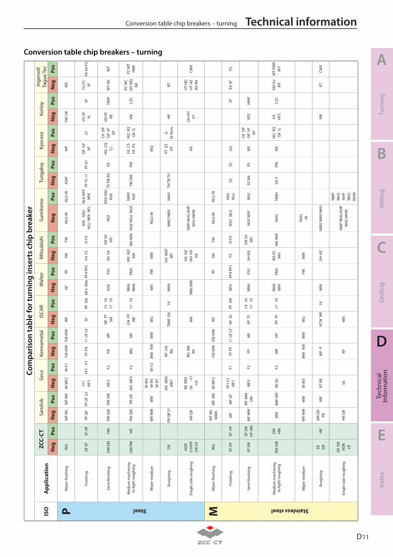
D 11
A
B
C
D
E
Turn
ing
Mill
ing
Dril
ling
Tech
nica
lIn
form
atio
nIn
dex
Technical informationConversion table chip breakers – turningCo
mpa
riso
n ta
ble
for t
urni
ng in
sert
s ch
ip b
reak
er
ISO
App
licat
ion
ZCC-
CTSa
ndvi
kSe
coKe
nnam
etal
ISCA
RW
alte
rM
itsub
ishi
Sum
itom
oTu
ngal
oyKy
ocer
aKo
rloy
Inge
rsol
lTa
gue
Tec
Neg
Pos
Neg
Pos
Neg
Pos
Neg
Pos
Neg
Pos
Neg
Pos
Neg
Pos
Neg
Pos
Neg
Pos
Neg
Pos
Neg
Pos
Neg
Pos
PW
iper
-fini
shin
gW
GW
F W
LW
F W
K W
-MF2
W-F
1FW
MW
FW M
WW
FN
FPF
SWFW
NLU
-WN
LU-W
ASW
WP
VW L
WW
S
Steel
Fini
shin
gD
F EF
SF H
FPF
QF
PF U
F 23
FF1
M
F1FF
1
F1
FF F
N
11 U
F LF
SF
PF S
MN
F3 N
S6PF
4 PF
5FH
FS
FJ F
VN
SE
NSU
NLU
NFA
NFL
NLU
NFP
N
FKTF
TS
17PF
01
DP
GP
VF
CFVG
VF
VLVF
FG F
CVF
FA S
A F
G
Sem
i-fini
shin
gD
M E
MH
MPM
QM
PM U
MM
F2F2
FNM
FN
F T
F
SM14
16
17
19
NS6
PS5
SH S
ASW
SV
MV
NSX
NSU
NSC
N
SKTS
TM
AS
PSH
Q C
Q
CJ
CK D
P
GP
VF
XP
VQ V
CVB
HM
PW
T M
LW
T
Med
ium
mac
hini
ng
to li
ght r
ough
ing
DM
PM
HR
PM Q
MPR
UR
M3
MF3
F2
MN
MF
GN
PP
N
R17
19
NM
4 N
M6
PM5
MV
MZ
M
AM
V M
WN
GE
NG
U N
UX
NM
U
NSF
TM D
MPM
GS
CS
H
S P
SH
Q X
Q
GK
GVM
C25
PC M
C M
T M
G
MF
PC M
T PM
R
Wip
er-m
ediu
mW
R W
MW
MW
-M3
W
-R4
W-R
7W
-F2
MW
RW
MW
WG
NM
PMM
WN
GU
-WW
Q
Roug
hing
DR
PR Q
R 31
M5
MR5
M
R7
RP U
N
RNTN
M G
N
19N
M9
GH
MAT
M
TN
MU
NM
X N
MU
TH T
R TU
PT G
T
HT
GSt
-form
HR
RT
Sing
le s
ide
roug
hing
HD
R31
HPR
DR
LRH
R Q
RR8
RR9
-5
6
-57
-UX
RH R
M
RP
NM
NR6
NR8
HA
HZ
H
H H
V
HX
NM
P N
HG
NH
P N
HU
NH
WH
XG
H V
H
VT
HT
HD
H
Y H
Z RX
RH
CMX
MW
iper
-fini
shin
gW
GW
F W
LW
MX
WF
WK
W-M
F2FW
MW
FW M
WW
FPF
SWFW
NLU
-WN
LU-W
Stainless steel
Fini
shin
gEF
DF
EF H
FM
FM
F U
FFF
1 F2
M
F1F1
FF
FP
11 U
F LF
NF
VL
PF S
MN
F4PF
4 PF
5FS
FJ F
VN
SU
NLU
NSU
N
LUSS
SSG
UVF
EA S
FFG
Sem
i-fini
shin
gEF
EM
EF E
MH
F H
MM
F M
MM
F M
M
UM
MF3
F2FP
MF
PP T
F14
16
17
19
NM
4
PS5
SH M
SSW
SV
MV
NEX
NU
PN
SUSS
SM
PSM
SCK
DP
G
P V
F
XPVP
2H
MP
Med
ium
mac
hini
ng
to li
ght r
ough
ing
EM D
MEM H
MM
MM
M U
MR6
56
F2M
PH
PPP
TF
17
19N
M4
NR4
PM5
MS
ES
MH
MV
MW
NG
UN
MU
SA S
PMM
SH
Q X
Q
GK
GH
SVP
3C2
5EM
SU
M
TM
T PM
R W
T
Wip
er m
ediu
mW
R W
MW
MW
-M3
M
W
RWM
WW
GPM
MW
NG
U-W
Roug
hing
ER
DR
HR
MR
QR
PRM
RR7
R8
MP
-PH
TW N
R19
NR4
GH
HZ
NM
U N
MX
NH
GVM
ETCM
X
Sing
le s
ide
roug
hing
ER D
R H
DR
LRH
R Q
R-5
6RP
NM
N
MP
NH
G N
HP
NH
U N
HW
NM
P N
HG
N
HP
NH
U
NH
W
Conversion table chip breakers – turning
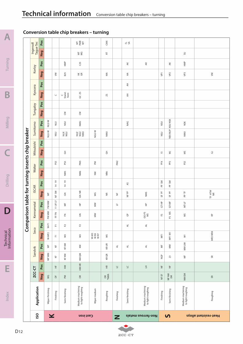
D 12
A
B
C
D
E
Turn
ing
Mill
ing
Dril
ling
Tech
nica
lIn
form
atio
nIn
dex
Technical information Conversion table chip breakers – turning
Com
pari
son
tabl
e fo
r tur
ning
inse
rts
chip
bre
aker
ISO
App
licat
ion
ZCC-
CTSa
ndvi
kSe
coKe
nnam
etal
ISCA
RW
alte
rM
itsub
ishi
Sum
itom
oTu
ngal
oyKy
ocer
aKo
rloy
Inge
rsol
lTa
gue
Tec
Neg
Pos
Neg
Pos
Neg
Pos
Neg
Pos
Neg
Pos
Neg
Pos
Neg
Pos
Neg
Pos
Neg
Pos
Neg
Pos
Neg
Pos
Neg
Pos
KW
iper
-Fin
ishi
ngW
GW
F W
MW
F W
-MF2
W-F
1FW
MW
FW M
WW
FN
LU-W
NLU
-W
Fin
ishi
ngD
FH
FKF
KFF1
F1FF
FN
11 U
F LF
NF
SM
14
19PS
5N
SUN
LUC
VM
Cast iron
Sem
i-fini
shin
gPM
HM
KF K
MKF
KM
M3
F2FN
MF
GN
14
19
NM
5PS
5G
HN
UX
NG
UN
SUCM
C St
and.
form
B25
HM
P
Med
ium
mac
hini
ng
to li
ght r
ough
ing
DR
HM
HR
KM Q
MKM
M
3 F2
UN
HP
GN
NR
NM
6PM
5N
UZ
NG
UN
MU
NM
UCM
GC
ZS
VK GR
C25
MT
MG
MT
PMR
WT
Wip
er m
ediu
mW
-M3
W-R
4
W-R
7M
W
M
WW
GN
MPM
NG
U-W
Roug
hing
DR
*NM
AH
RKR
QR
KR U
RM
5 N
R
NR6
GH
NM
UZS
MA
RTCM
X
NFi
nish
ing
LCA
LLF
NF
PM2
Non-ferrous metals
Sem
i-fini
shin
gLC
AL
AL
GP
NF
PPA
SN
AGA
HA
HH
AA
KFL SA
Med
ium
mac
hini
ng
to li
ght r
ough
ing
LHA
LA
LG
G-F
S M
SH
PN
MS
AR
S F
inis
hing
NF
EFN
FN
GP
MF
MF1
FS
GT-
HP
SF P
FPF
SM
PF4
FJN
SUN
SUVP
1
Sem
i-fini
shin
gN
F N
M
EMN
F23
MM
MF1
M1
FS
MS
GT-
MF
SF P
FPF
SM
PF5
MJ
NEX
NU
PN
SU N
SKVP
2A
K
Med
ium
mac
hini
ng
to li
ght r
ough
ing
NM
EM
MF
MM
UM
M1
MS
MT-
LFPP
TF
PS5
MS
NM
UN
SKVP
3H
MP
SU
Heat-resistant alloys
Roug
hing
ERSR
MR3
MR4
RPTF
HTW
N
RG
JVM
Conversion table chip breakers – turning
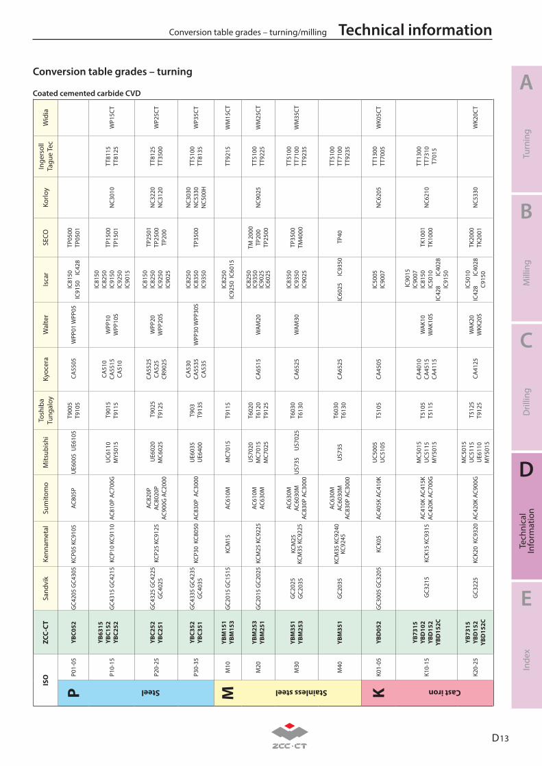
D 13
A
B
C
D
E
Turn
ing
Mill
ing
Dril
ling
Tech
nica
lIn
form
atio
nIn
dex
Technical informationConversion table grades – turning/millingIS
O
ZCC-
CTSa
ndvi
kKe
nnam
etal
Sum
itom
oM
itsub
ishi
Tosh
iba
Tung
aloy
Kyoc
era
Wal
ter
Isca
rSE
COKo
rloy
Inge
rsol
lTa
gue
Tec
Wid
ia
PP0
1-05
YBC0
52G
C420
5 G
C430
5 KC
P05
KC91
05AC
805P
UE6
005
UE6
105
T900
5T9
105
CA
5505
WPP
01 W
PP05
IC81
50
IC91
50
IC42
8TP
0500
TP05
01
Steel
P10-
15
YB63
15YB
C152
YBC2
52
GC4
315
GC4
215
KCP
10 K
C911
0 AC
810P
AC7
00G
U
C611
0
MY5
015
T90
15T9
115
CA51
0CA
5515
CA51
0
WPP
10
W
PP10
S
IC81
50IC
8250
IC91
50IC
9250
IC90
15
TP15
00
TP
1501
N
C301
0TT
8115
TT
8125
WP1
5CT
P20-
25YB
C252
YBC2
51
GC4
325
GC4
225
GC4
025
KCP
25 K
C912
5AC
820P
AC
8020
P AC
900G
AC2
000
UE6
020
M
C602
5
T
9025
T912
5
CA55
25
CA
525
CR90
25
WPP
20
W
PP20
S
IC81
50IC
8250
IC92
50IC
9025
TP2
501
TP25
00
TP20
0
NC3
220
NC3
120
TT81
25
TT35
00
WP2
5CT
P30-
35YB
C352
YBC3
51G
C433
5 G
C423
5 G
C403
5 K
CP30
KC8
050
AC83
0P A
C300
0 U
E603
5
U
E640
0T9
03 T
9135
CA53
0CA
5535
CA53
5
W
PP30
WPP
30S
IC82
50IC
8350
IC93
50TP
3500
NC3
030
NC5
330
NC5
00H
TT51
00
TT81
35W
P35C
T
MM
10
YBM
151
YBM
153
GC2
015
GC1
515
KCM
15AC
610M
MC7
015
T911
5IC
8250
IC92
50 I
C601
5TT
9215
W
M15
CT
Stainless steel
M20
YB
M25
3
YBM
251
GC2
015
GC2
025
KCM
25 K
C922
5AC
610M
AC
630M
US7
020
MC7
015
M
C702
5
T602
0T6
120
T912
5CA
6515
WA
M20
IC82
50IC
9350
IC90
25IC
6025
TM 2
000
TP20
0TP
2500
N
C902
5TT
5100
TT
9225
W
M25
CT
M30
YBM
351
YBM
253
GC2
025
G
C203
5
KCM
25KC
M35
KC9
225
AC63
0M
AC60
30M
AC
830P
AC3
000
US7
35
US7
025
T603
0
T6
130
CA65
25W
AM
30IC
8350
IC93
50IC
9025
TP35
00
TM40
00
TT51
00
TT71
00
TT92
35W
M35
CT
M40
YBM
351
GC2
035
KCM
35 K
C924
0 KC
9245
AC63
0M
AC60
30M
AC
830P
AC3
000
US7
35
T6
030
T613
0CA
6525
IC60
25
IC9
350
TP4
0TT
5100
TT
7100
TT
9235
KK0
1-05
YBD
052
G
C300
5 G
C320
5 KC
K05
AC40
5K A
C410
KU
C500
5
UC5
105
T510
5CA
4505
IC50
05
IC
9007
N
C620
5TT
1300
TT
7005
WK0
5CT
Cast iron
K10-
15
YB73
15YB
D10
2YB
D15
2
YBD
152C
GC3
215
K
CK15
KC9
315
AC41
0K A
C415
K AC
420K
AC7
00G
MC5
015
U
C511
5
MY5
015
T510
5T5
115
CA40
10CA
4515
CA41
15
WA
K10
WA
K10S
IC9
015
IC90
07IC
8150
IC50
10IC
428
IC40
28IC
9150
TK1
001
TK
1000
N
C621
0 TT
1300
TT
7310
T7
015
K20-
25YB
7315
YBD
152
YBD
152C
G
C322
5 K
CK20
KC9
320
AC42
0K A
C900
G
MC5
015
U
C511
5
UE6
110
M
Y501
5
T51
25T9
125
CA
4125
WA
K20
W
KK20
S
IC50
10IC
428
IC40
28
C915
0
TK20
00
TK20
01
NC5
330
WK2
0CT
Coated cemented carbide CVD
Conversion table grades – turning
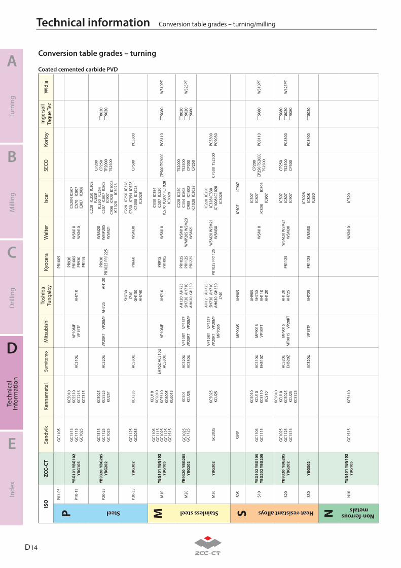
D 14
A
B
C
D
E
Turn
ing
Mill
ing
Dril
ling
Tech
nica
lIn
form
atio
nIn
dex
Technical information Conversion table grades – turning/milling
ISO
ZC
C-CT
Sand
vik
Kenn
amet
alSu
mito
mo
Mits
ubis
hiTo
shib
a Tu
ngal
oyKy
ocer
aW
alte
rIs
car
SECO
Korlo
yIn
gers
oll
Tagu
e Te
cW
idia
PP0
1-05
GC1
105
PR10
05
P10-
15YB
G10
1 YB
G10
2 YB
G10
5
GC1
515
GC1
115
GC1
025
KC50
10KC
5510
KC72
15KC
7315
AC51
0UVP
10M
F
VP
15TF
AH
710
PR93
0PR
1005
PR93
0
PR11
5
WSM
10
WXN
10
IC52
0N IC
507
IC57
0
IC80
7IC
907
IC
908
Steel
P20-
25YB
9320
YBG
205
YB
G20
2
GC1
515
GC1
125
GC1
025
KC50
25KC
5525
KU25
T
AC
520U
VP20
RT
VP2
0MF
AH
725
AH
120
PR93
0PR
1025
PR1
225
WSM
20
WM
P20S
W
SM21
IC22
8 I
C250
IC3
08
IC82
8IC
350
IC3
54IC
507
IC8
07 I
C808
IC
907
IC90
8 I
C928
IC1
008
IC10
28
IC
3028
CP20
0
CP
250
TP
2000
TS
2500
TT80
20
TT90
20
P30-
35YB
G30
2G
C112
5G
C203
5KC
7335
AC53
0U
SH73
0J7
40G
H13
0A
H74
0
PR66
0W
SM30
IC22
8 I
C250
IC3
28
IC33
0 I
C354
IC5
28
IC10
08 I
C102
8
IC
3028
CP50
0PC
5300
MM
10
YBG
101
YBG
102
YBG
105
GC1
105
GC1
115
GC1
025
GC1
125
GC1
515
KCU
10KC
5010
KC55
10
KC60
05KC
6015
EH10
Z AC
510U
AC
530U
VP10
MF
AH
710
PR91
5PR
1005
WSM
10
IC33
0 IC
354
IC50
7 IC
520
IC57
0 IC
807
IC10
28
IC30
28
CP50
0 TS
2000
PC
8110
TT50
80W
S10P
T
Stainless steel
M20
YB
9320
YBG
205
YB
G20
2G
C102
5G
C112
5 KC
501
KCU
25AC
520U
AC
530U
VP10
RT
VP1
5TF
VP
20RT
V
P20M
F
AH
120
AH
725
SH73
0 A
H71
0
AH
630
GH
330
PR10
25
PR11
25
PR12
25
WSM
10
WM
P20S
WSM
20
WSM
21
IC22
8 IC
250
IC35
4 IC
808
IC90
8
IC10
08IC
1028
IC3
028
TS20
00
TS25
00
CP20
0
CP25
0
TT80
20
TT90
20
TT
9080
WS2
5PT
M30
YBG
302
GC2
035
KC50
25KC
U25
VP10
RT
VP1
5TF
VP
20RT
V
P20M
F M
P703
5
AH
12
AH
725
SH73
0 A
H71
0
AH
630
GH
330
J740
PR10
25 P
R112
5W
SM20
WSM
21
WSM
30
IC22
8 IC
250
IC32
8 IC
330
IC10
08 IC
1028
IC
3028
CP50
0 T
S250
0PC
5300
PC
9030
SS0
5S0
5F
M
P900
5
AH
905
IC
507
IC9
07
S10
YBG
102
YBG
105
YBG
202
YBG
205
GC1
105
GC1
115
KC50
10KC
U10
KC55
10KC
S10
AC51
0U
EH
510Z
MP9
015
VP10
RT
AH
905
SH73
0A
H11
0
A
H12
0
WSM
10
IC50
7IC
807
IC80
8
IC
806
IC90
7
CP20
0
CP25
0 TS
2000
TS
2500
PC81
10TT
5080
WS1
0PT
Heat-resistant alloys
S20
YB93
20 Y
BG20
5
YBG
202
GC1
025
GC1
125
GC1
515
KC50
10KC
U10
KC50
25KC
U25
KC55
25
AC52
0U
EH52
0ZM
P901
5
M
T901
5
VP2
0RT
AH
120
AH
725
PR11
25
WSM
20 W
SM21
W
SM30
IC50
7IC
807
IC90
7
CP25
0
TS25
00
CP50
0 PC
5300
TT50
80
TT80
20
TT90
80W
S25P
T
S30
YBG
302
AC52
0U
VP
15TF
AH
725
PR11
25
WSM
30IC
3028
IC80
8IC
830
PC54
00TT
8020
NN
10YB
G10
1 YB
G10
2 YB
G10
5G
C151
5KC
5410
WXN
10IC
520
Non-ferrous metals
Coated cemented carbide PVD
Conversion table grades – turning
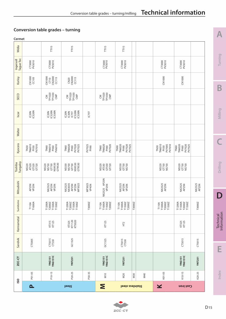
D 15
A
B
C
D
E
Turn
ing
Mill
ing
Dril
ling
Tech
nica
lIn
form
atio
nIn
dex
Technical informationConversion table grades – turning/millingIS
O
ZCC-
CTSa
ndvi
kKe
nnam
etal
Sum
itom
oM
itsub
ishi
Tosh
iba
Tung
aloy
Kyoc
era
Wal
ter
Isca
rSE
COKo
rloy
Inge
rsol
lTa
gue
Tec
Wid
ia
PP0
1-05
CT5
005
T110
A
T100
0AA
P25N
VP25
N
NS5
20 A
T520
GT5
20G
T720
TN30
TN60
10PV
30PV
7010
IC20
NIC
520N
CN
1000
CC10
5
C
T300
0
PV
3010
Steel
P10-
15 Y
NG
151
YN
G15
1C C
T501
5
C
T530
KT31
5
KT12
5
T120
0A
T2
000Z
T150
0A
T1
500Z
NX2
525
AP2
5N
VP25
N
NS5
20N
S730
GT7
30N
S953
0G
T953
0
TN60
TN60
10PV
60PV
6010
IC20
NIC
520N
IC53
0N
CM
TP
1020
TP10
30
CM
P
CN10
00
C
T10
CN20
00
CC11
5
CT3
000
PV30
10
TTI1
5
P20-
25YN
T251
G
C152
5 KT
325
KT
1120
KT
5020
T120
0A
T2
000Z
T150
0A
T1
500Z
NX2
525
NX3
035
AP2
5N
VP25
N
M
P302
5
NS5
30N
S730
G
T730
NS9
530
G
T953
0
TN60
TN60
20PV
60PV
7020
PV70
25
IC20
NIC
30N
IC75
TIC
520N
IC53
0N
CM
TP
1020
TP10
30
CM
P
CN20
CN
2000
CC
115
TTI1
5
P30-
35T3
000Z
MP3
025
VP
45N
PV70
25PV
90IC
75T
MM
10
YN
G15
1
YNG
151C
GC1
525
KT12
5
T110
A
T1
000A
T150
0Z
T200
0Z
NX2
525
A
P25N
VP
25N
NS5
20AT
530
GT5
30G
T720
TN60
TN60
20PV
60PV
7020
CM
TP
1020
TP10
30
CM
P
CT3
000
PV30
10
TT
I15
Stainless steel
M20
YN
T251
CT5
015
CT5
30H
T2
T110
A
T1
000A
T150
0Z
T200
0Z
NX2
525
A
P25N
VP
25N
NS5
30G
T730
NS7
30
TN90
TN60
20PV
90PV
7020
PV70
25
CT3
000
PV30
10
TT
I15
M30
T300
0Z
M40
KK0
1-05
T110
A
T100
0A
T2
000Z
T150
0Z
NX2
525
A
P25N
NS5
20G
T730
NS7
30
TN30
TN60
10PV
30PV
7005
PV70
10
CN10
00C
T300
0
PV
3010
Cast iron
K10-
15 Y
NG
151
YNG
151C
CT5
015
KT32
5
KT12
5
T120
0A
T1
500A
T2
000Z
T150
0Z
NX2
525
A
P25N
NS5
20G
T730
NS7
30
TN60
TN60
20PV
60PV
7020
PV70
25
CN10
00C
T300
0
PV
3010
K20-
25YN
T251
CT5
015
T300
0ZN
X252
5
AP2
5N
Cermet
Conversion table grades – turning
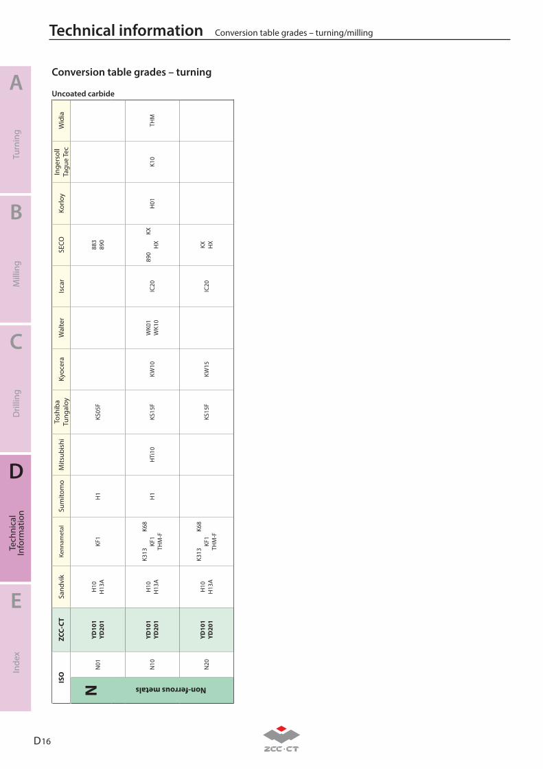
D 16
A
B
C
D
E
Turn
ing
Mill
ing
Dril
ling
Tech
nica
lIn
form
atio
nIn
dex
Technical information Conversion table grades – turning/milling
ISO
ZC
C-CT
Sand
vik
Kenn
amet
alSu
mito
mo
Mits
ubis
hiTo
shib
a Tu
ngal
oyKy
ocer
aW
alte
rIs
car
SECO
Korlo
yIn
gers
oll
Tagu
e Te
cW
idia
NN
01YD
101
YD
201
H10
H13
AKF
1H
1
KS
05F
883
890
Non-ferrous metals
N10
YD10
1
YD20
1H
10
H
13A
K313
K68
KF1
THM
-FH
1
H
Ti10
KS15
FKW
10W
K01
W
K10
IC20
890
KX
HX
H01
K10
THM
N20
YD10
1
YD20
1H
10
H
13A
K313
K68
KF1
THM
-FKS
15F
KW15
IC20
KX
H
X
Uncoated carbide
Conversion table grades – turning
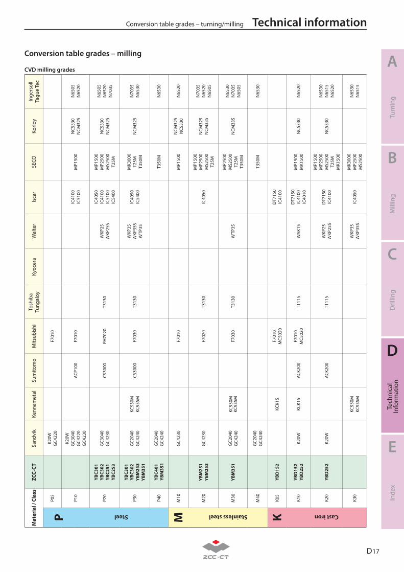
D 17
A
B
C
D
E
Turn
ing
Mill
ing
Dril
ling
Tech
nica
lIn
form
atio
nIn
dex
Technical informationConversion table grades – turning/millingM
ater
ial /
Cla
ss
ZCC-
CTSa
ndvi
kKe
nnam
etal
Sum
itom
oM
itsub
ishi
Tosh
iba
Tung
aloy
Kyoc
era
Wal
ter
Isca
rSE
COKo
rloy
Inge
rsol
lTa
gue
Tec
PP0
5K2
0WG
C422
0F7
010
P10
K20W
GC3
040
GC4
220
GC4
230
ACP1
00F7
010
IC41
00IC
5100
MP1
500
NC5
330
NCM
325
IN65
05IN
6520
Steel
P20
YBC3
01
YBC3
02YB
C251
YB
C253
GC3
040
GC4
230
CS30
00FH
7020
T313
0W
KP25
WKP
25S
IC40
50IC
4100
IC51
00IC
5400
MP1
500
MP2
500
MS2
500
T25M
NC5
330
NCM
325
IN65
05IN
6520
IN70
35
P30
YBC3
01
YBC3
02YB
M25
3 YB
M35
1
GC2
040
GC4
240
KC93
0MKC
935M
CS30
00F7
030
T313
0W
KP35
WKP
35S
WTP
35
IC40
50IC
5400
MK3
000
T25M
T350
MN
CM32
5IN
7035
IN65
30
P40
YBC4
01 Y
BM35
1G
C204
0G
C424
0T3
50M
IN65
30
MM
10
GC4
230
F701
0M
P150
0N
CM32
5N
C533
0IN
6520
Stainless steel
M20
YB
M25
1YB
M25
3G
C423
0F7
020
T313
0IC
4050
MP1
500
MP2
500
MS2
500
T25M
NCM
325
NCM
335
IN70
35IN
6520
IN65
05
M30
YBM
351
GC2
040
GC4
240
KC93
0MKC
935M
F703
0T3
130
WTP
35
MP2
500
MS2
500
T25M
T350
M
NCM
335
IN65
30IN
7035
IN65
05
M40
GC2
040
GC4
240
T350
MIN
6530
KK0
5YB
D15
2KC
K15
F701
0M
C502
0D
T715
0IC
4100
Cast iron
K10
YBD
152
YBD
252
K20W
KCK1
5AC
K200
F701
0M
C502
0T1
115
WA
K15
DT7
150
IC41
00IC
4010
MP1
500
MK1
500
NC5
330
IN65
20
K20
YBD
252
K20W
ACK2
00T1
115
WKP
25W
KP25
SD
T715
0IC
4100
MP1
500
MP2
500
MS2
500
T25M
MK1
500
NC5
330
IN65
30IN
6515
IN65
20
K30
KC93
0MKC
935M
WKP
35W
KP35
SIC
4050
MK3
000
MP2
500
MS2
500
IN65
30IN
6515
CVD milling grades
Conversion table grades – milling
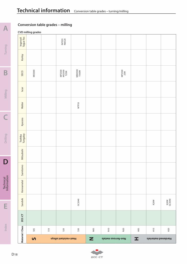
D 18
A
B
C
D
E
Turn
ing
Mill
ing
Dril
ling
Tech
nica
lIn
form
atio
nIn
dex
Technical information Conversion table grades – turning/milling
Mat
eria
l / C
lass
ZC
C-CT
Sand
vik
Kenn
amet
alSu
mito
mo
Mits
ubis
hiTo
shib
a Tu
ngal
oyKy
ocer
aW
alte
rIs
car
SECO
Korlo
yIn
gers
oll
Tagu
e Te
c
SS0
5M
K300
0
Heat-resistant alloys
S10
S20
MP2
500
MS2
500
T25M
IN70
35IN
6520
S30
GC2
040
WTP
35M
M45
00T3
50M
NN
05
Non-ferrous metals
N10
N20
MP2
500
25M
HH
05
Hardened materiels
H10
K20W
H20
K20W
GC3
040
CVD milling grades
Conversion table grades – milling
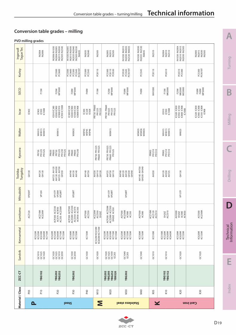
D 19
A
B
C
D
E
Turn
ing
Mill
ing
Dril
ling
Tech
nica
lIn
form
atio
nIn
dex
Technical informationConversion table grades – turning/millingM
ater
ial /
Cla
ss
ZCC-
CTSa
ndvi
kKe
nnam
etal
Sum
itom
oM
itsub
ishi
Tosh
iba
Tung
aloy
Kyoc
era
Wal
ter
Isca
rSE
COKo
rloy
Inge
rsol
lTa
gue
Tec
PP0
5AC
Z120
VP05
HT
GH
130
IC90
3
P10
YBG
102
GC1
010
GC1
025
GC1
020
KC52
2M
KC52
5MKC
610M
KC
643M
KC71
5M
ACZ1
0MAC
Z20W
VP10
HA
H12
0G
H13
0
PR73
0PR
1225
PR15
25
WH
X15
WH
H15
WXM
15
IC90
3IC
950
IC10
08F1
5MIN
2004
IN20
06
Steel
P20
YBG
202
YBG
252
GC1
020
GC1
025
GC1
010
GC2
030
KC52
2M
KC52
5MKC
643M
KC
715M
KC72
5M
ACP2
00 A
CZ33
0AC
X70
ACW
30AC
350
ACZ
50M
VP15
TFVP
20M
VP20
RT
AH
725
AH
120
AH
130
AH
330
AH
725
AH
730
GH
330
PR63
0 PR
830
PR73
0PR
1225
PR12
30PR
1525
WXM
15
IC81
0 IC
380
IC83
0 IC
900
IC90
8 IC
910
IC95
0 IC
1008
F25M
MP3
000
PC35
00PC
3600
IN20
06 IN
1030
IN20
04 IN
2005
IN20
15 IN
2030
IN25
05 IN
2540
P30
YBG
302
GC1
030
GC2
030
KC53
0MKC
725M
KC73
5M
ACP2
00 A
CP30
0AC
Z50M
ACZ
330
ACZ3
50 A
CX70
ACW
30 A
C350
VP30
RTA
H74
0A
H13
0A
H14
0
PR63
0PR
660
PR83
0PR
1230
WXM
35
IC30
0 IC
328
IC83
0 IC
900
IC92
8 IC
350
IC80
8 IC
908
F30M
MP3
000
PC35
00PC
3600
PC53
00PC
3545
PC95
70T
IN10
30 IN
2005
IN20
15 IN
2030
IN20
35 IN
2040
IN25
05 IN
2530
IN40
35
P40
GC1
030
KC73
5MAC
P300
ACZ3
50A
H14
0A
H75
0
WXP
45W
SP45
WSP
46
IC30
0IC
328
IC92
8F4
0MPC
5300
PC35
45IN
2035
IN20
40
MM
10
GC1
020
KC52
2M K
C610
MKC
643M
KC7
15M
ACZ2
0WAC
Z350
EH20
Z
AH
330
GH
110
GH
130
PR73
0 P
R122
5PR
660
PR1
525
PR73
0 P
R660
PR12
25PR
1525
F15M
PC81
10IN
2505
M20
YBG
202
YBG
205
YBG
252
YB93
20
GC1
020
GC1
025
GC1
030
GC2
03
KC52
2MKC
525M
KC61
0MKC
715M
KC72
5M
ACP2
00 A
CZ50
MAC
Z20M
ACZ
350
EH20
Z A
C350
VP15
TFVP
20RT
AH
725
AH
730
GH
110
PR73
0 P
R102
5PR
660
PR1
225
PR15
25W
XM15
PR73
0 P
R660
PR10
25PR
1225
PR15
25
F25M
MP3
000
PC53
00PC
8110
PC95
30
IN20
05IN
2015
IN25
05
Stainless steel
M30
YBG
302
GC1
040
GC2
03
KC52
5MKC
530M
KC72
5MKC
735M
ACP3
00AC
Z50M
ACX8
0AC
350
VP30
RT
AH
740
AH
120
AH
130
GH
330
GH
340
F30M
MP3
000
PC95
30PC
3545
PC95
70T
IN10
30 I
N20
15IN
2030
IN
2035
IN25
30 I
N40
35
M40
GC1
040
KC53
0MKC
735M
ACP3
00AC
X80
AH
140
AH
750
GH
330
GH
340
WSM
35W
SM36
WXM
35F4
0MPC
3545
IN10
30 I
N20
30IN
2035
IN
2530
IN40
35
KK0
5G
C101
0KC
510M
ACZ1
0MAC
Z120
ACZ3
10A
H33
0PR
905
PR12
10PR
1510
MH
1000
PC81
10IN
2510
K10
YBG
102
YBG
152
GC1
010
KC51
0MKC
520M
KC62
0MKC
643M
EH20
ZAC
Z310
AH
120
AH
330
AH
725
PR90
5PR
1210
PR15
10
WXH
15W
HH
15W
XM15
IC81
0IC
950
IC10
08
F15M
MK2
000
PC65
10IN
2004
IN20
10IN
2510
Cast iron
K20
GC1
020
KC52
0MKC
620M
KC72
5M
ACK3
00EH
20Z
ACX8
0AC
W30
VP15
TFG
H13
0W
KK25
IC32
8 IC
830
IC95
0 IC
350
IC80
8 IC
908
IC10
08
F25M
MK2
000
MO
3000
PC65
10PC
5300
IN10
30 I
N20
04IN
2010
IN
2015
IN20
30 I
N25
05
K30
GC1
020
KC62
0MKC
725M
ACK3
00AC
Z50M
IC32
8 IC
830
IC90
0 IC
908
IC35
0 IC
808
IC90
8
F30M
F40M
MP3
000
PC53
00PC
9570
T
IN20
05IN
2015
IN20
30IN
2505
PVD milling grades
Conversion table grades – milling
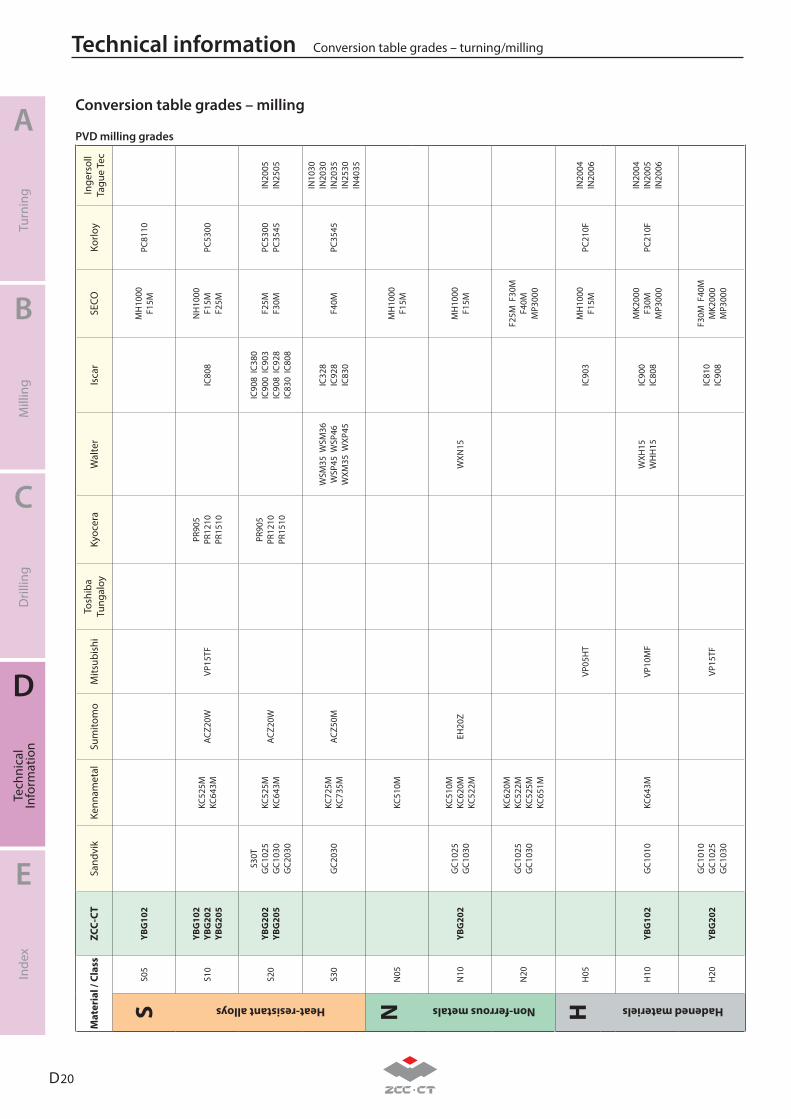
D 20
A
B
C
D
E
Turn
ing
Mill
ing
Dril
ling
Tech
nica
lIn
form
atio
nIn
dex
Technical information Conversion table grades – turning/milling
Mat
eria
l / C
lass
ZC
C-CT
Sand
vik
Kenn
amet
alSu
mito
mo
Mits
ubis
hiTo
shib
a Tu
ngal
oyKy
ocer
aW
alte
rIs
car
SECO
Korlo
yIn
gers
oll
Tagu
e Te
c
SS0
5YB
G10
2M
H10
00F1
5MPC
8110
Heat-resistant alloys
S10
YBG
102
YBG
202
YBG
205
KC52
5MKC
643M
ACZ2
0WVP
15TF
PR90
5PR
1210
PR15
10IC
808
NH
1000
F15M
F25M
PC53
00
S20
YBG
202
YBG
205
S30T
GC1
025
GC1
030
GC2
030
KC52
5MKC
643M
ACZ2
0WPR
905
PR12
10PR
1510
IC90
8 IC
380
IC90
0 IC
903
IC90
8 IC
928
IC83
0 IC
808
F25M
F30M
PC53
00PC
3545
IN20
05IN
2505
S30
GC2
030
KC72
5MKC
735M
ACZ5
0MW
SM35
WSM
36W
SP45
WSP
46W
XM35
WXP
45
IC32
8
IC92
8IC
830
F40M
PC35
45
IN10
30IN
2030
IN20
35IN
2530
IN40
35
NN
05KC
510M
MH
1000
F15M
Non-ferrous metals
N10
YBG
202
GC1
025
GC1
030
KC51
0MKC
620M
KC52
2MEH
20Z
WXN
15M
H10
00F1
5M
N20
GC1
025
GC1
030
KC62
0MKC
522M
KC52
5MKC
651M
F25M
F30
MF4
0MM
P300
0
HH
05VP
05H
TIC
903
MH
1000
F15M
PC21
0FIN
2004
IN20
06
Hadened materiels
H10
YBG
102
GC1
010
KC64
3MVP
10M
FW
XH15
WH
H15
IC90
0IC
808
MK2
000
F30M
MP3
000
PC21
0FIN
2004
IN20
05IN
2006
H20
YBG
202
GC1
010
GC1
025
GC1
030
VP15
TFIC
810
IC90
8
F30M
F40
MM
K200
0M
P300
0
S
PVD milling grades
Conversion table grades – milling
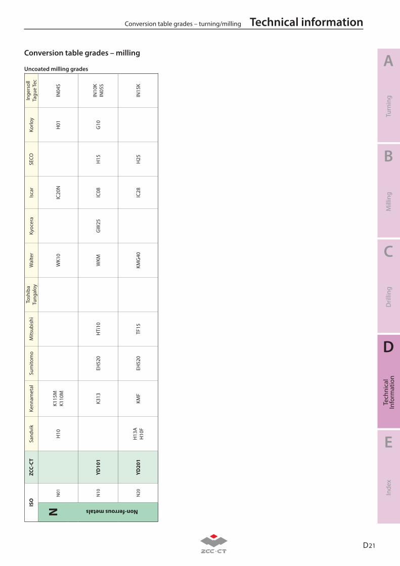
D 21
A
B
C
D
E
Turn
ing
Mill
ing
Dril
ling
Tech
nica
lIn
form
atio
nIn
dex
Technical informationConversion table grades – turning/millingIS
O
ZCC-
CTSa
ndvi
kKe
nnam
etal
Sum
itom
oM
itsub
ishi
Tosh
iba
Tung
aloy
Wal
ter
Kyoc
era
Isca
rSE
COKo
rloy
Inge
rsol
lTa
gue
Tec
NN
01H
10K1
15M
K110
MW
K10
IC20
NH
01IN
04S
Non-ferrous metals
N10
YD10
1K3
13EH
520
HTi
10W
KMG
W25
IC08
H15
G10
IN10
KIN
05S
N20
YD20
1H
13A
H10
FKM
FEH
520
TF15
KMG
40IC
28H
25IN
15K
Uncoated milling grades
Conversion table grades – milling
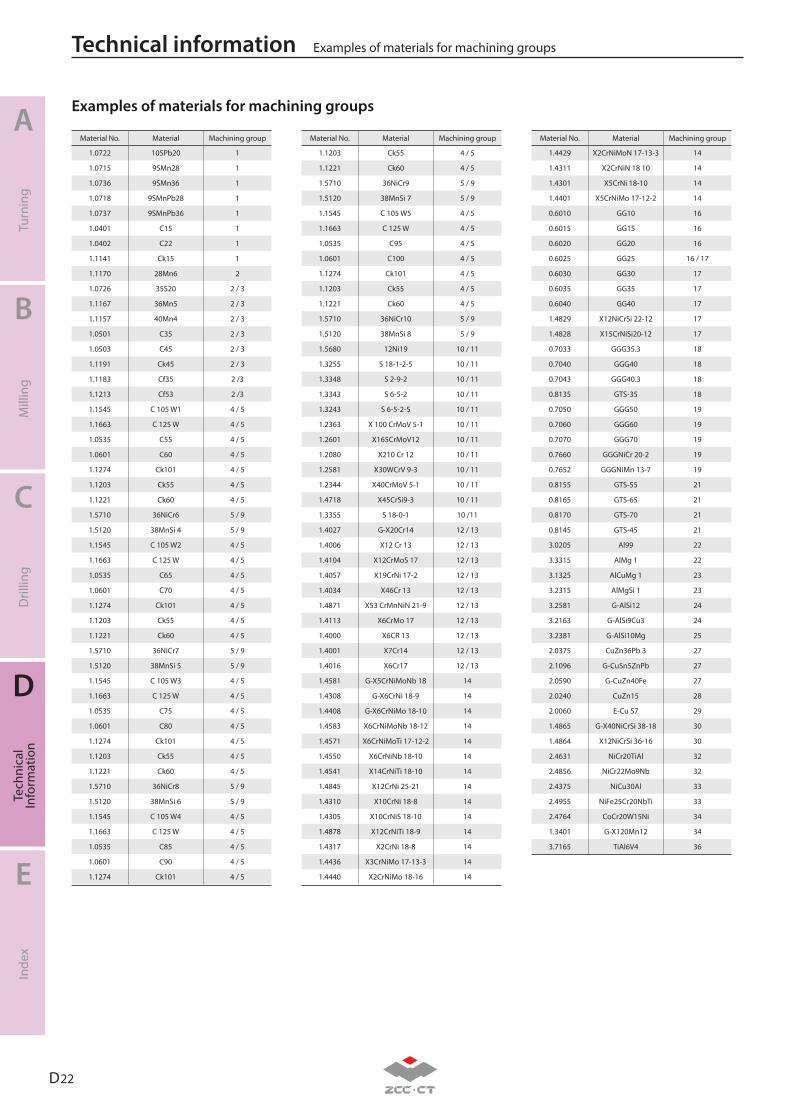
D 22
A
B
C
D
E
Turn
ing
Mill
ing
Dril
ling
Tech
nica
lIn
form
atio
nIn
dex
Technical information Examples of materials for machining groups
Examples of materials for machining groups
1.0722 10SPb20 1
1.0715 9SMn28 1
1.0736 9SMn36 1
1.0718 9SMnPb28 1
1.0737 9SMnPb36 1
1.0401 C15 1
1.0402 C22 1
1.1141 Ck15 1
1.1170 28Mn6 2
1.0726 35S20 2 / 3
1.1167 36Mn5 2 / 3
1.1157 40Mn4 2 / 3
1.0501 C35 2 / 3
1.0503 C45 2 / 3
1.1191 Ck45 2 / 3
1.1183 Cf35 2 /3
1.1213 Cf53 2 /3
1.1545 C 105 W1 4 / 5
1.1663 C 125 W 4 / 5
1.0535 C55 4 / 5
1.0601 C60 4 / 5
1.1274 Ck101 4 / 5
1.1203 Ck55 4 / 5
1.1221 Ck60 4 / 5
1.5710 36NiCr6 5 / 9
1.5120 38MnSi 4 5 / 9
1.1545 C 105 W2 4 / 5
1.1663 C 125 W 4 / 5
1.0535 C65 4 / 5
1.0601 C70 4 / 5
1.1274 Ck101 4 / 5
1.1203 Ck55 4 / 5
1.1221 Ck60 4 / 5
1.5710 36NiCr7 5 / 9
1.5120 38MnSi 5 5 / 9
1.1545 C 105 W3 4 / 5
1.1663 C 125 W 4 / 5
1.0535 C75 4 / 5
1.0601 C80 4 / 5
1.1274 Ck101 4 / 5
1.1203 Ck55 4 / 5
1.1221 Ck60 4 / 5
1.5710 36NiCr8 5 / 9
1.5120 38MnSi 6 5 / 9
1.1545 C 105 W4 4 / 5
1.1663 C 125 W 4 / 5
1.0535 C85 4 / 5
1.0601 C90 4 / 5
1.1274 Ck101 4 / 5
1.1203 Ck55 4 / 5
1.1221 Ck60 4 / 5
1.5710 36NiCr9 5 / 9
1.5120 38MnSi 7 5 / 9
1.1545 C 105 W5 4 / 5
1.1663 C 125 W 4 / 5
1.0535 C95 4 / 5
1.0601 C100 4 / 5
1.1274 Ck101 4 / 5
1.1203 Ck55 4 / 5
1.1221 Ck60 4 / 5
1.5710 36NiCr10 5 / 9
1.5120 38MnSi 8 5 / 9
1.5680 12Ni19 10 / 11
1.3255 S 18-1-2-5 10 / 11
1.3348 S 2-9-2 10 / 11
1.3343 S 6-5-2 10 / 11
1.3243 S 6-5-2-5 10 / 11
1.2363 X 100 CrMoV 5-1 10 / 11
1.2601 X165CrMoV12 10 / 11
1.2080 X210 Cr 12 10 / 11
1.2581 X30WCrV 9-3 10 / 11
1.2344 X40CrMoV 5-1 10 / 11
1.4718 X45CrSi9-3 10 / 11
1.3355 S 18-0-1 10 /11
1.4027 G-X20Cr14 12 / 13
1.4006 X12 Cr 13 12 / 13
1.4104 X12CrMoS 17 12 / 13
1.4057 X19CrNi 17-2 12 / 13
1.4034 X46Cr 13 12 / 13
1.4871 X53 CrMnNiN 21-9 12 / 13
1.4113 X6CrMo 17 12 / 13
1.4000 X6CR 13 12 / 13
1.4001 X7Cr14 12 / 13
1.4016 X6Cr17 12 / 13
1.4581 G-X5CrNiMoNb 18 14
1.4308 G-X6CrNi 18-9 14
1.4408 G-X6CrNiMo 18-10 14
1.4583 X6CrNiMoNb 18-12 14
1.4571 X6CrNiMoTi 17-12-2 14
1.4550 X6CrNiNb 18-10 14
1.4541 X14CrNiTi 18-10 14
1.4845 X12CrNi 25-21 14
1.4310 X10CrNi 18-8 14
1.4305 X10CrNiS 18-10 14
1.4878 X12CrNiTi 18-9 14
1.4317 X2CrNi 18-8 14
1.4436 X3CrNiMo 17-13-3 14
1.4440 X2CrNiMo 18-16 14
1.4429 X2CrNiMoN 17-13-3 14
1.4311 X2CrNiN 18 10 14
1.4301 X5CrNi 18-10 14
1.4401 X5CrNiMo 17-12-2 14
0.6010 GG10 16
0.6015 GG15 16
0.6020 GG20 16
0.6025 GG25 16 / 17
0.6030 GG30 17
0.6035 GG35 17
0.6040 GG40 17
1.4829 X12NiCrSi 22-12 17
1.4828 X15CrNiSi20-12 17
0.7033 GGG35.3 18
0.7040 GGG40 18
0.7043 GGG40.3 18
0.8135 GTS-35 18
0.7050 GGG50 19
0.7060 GGG60 19
0.7070 GGG70 19
0.7660 GGGNiCr 20-2 19
0.7652 GGGNiMn 13-7 19
0.8155 GTS-55 21
0.8165 GTS-65 21
0.8170 GTS-70 21
0.8145 GTS-45 21
3.0205 Al99 22
3.3315 AlMg 1 22
3.1325 AlCuMg 1 23
3.2315 AlMgSi 1 23
3.2581 G-AlSi12 24
3.2163 G-AlSi9Cu3 24
3.2381 G-AlSi10Mg 25
2.0375 CuZn36Pb 3 27
2.1096 G-CuSn5ZnPb 27
2.0590 G-CuZn40Fe 27
2.0240 CuZn15 28
2.0060 E-Cu 57 29
1.4865 G-X40NiCrSi 38-18 30
1.4864 X12NiCrSi 36-16 30
2.4631 NiCr20TiAl 32
2.4856 NiCr22Mo9Nb 32
2.4375 NiCu30Al 33
2.4955 NiFe25Cr20NbTi 33
2.4764 CoCr20W15Ni 34
1.3401 G-X120Mn12 34
3.7165 TiAl6V4 36
Material No. Material Machining group Material No. Material Machining group Material No. Material Machining group
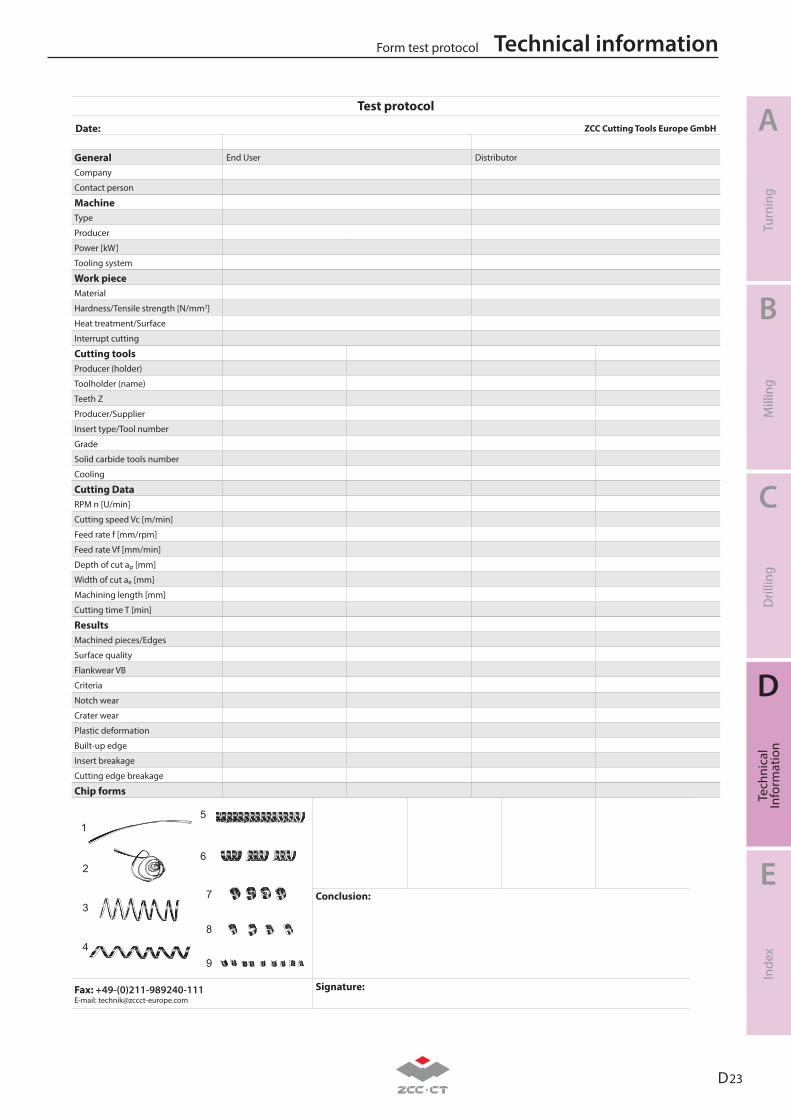
D 23
A
B
C
D
E
Turn
ing
Mill
ing
Dril
ling
Tech
nica
lIn
form
atio
nIn
dex
Technical informationForm test protocol
Test protocol
Date: ZCC Cutting Tools Europe GmbH
General End User Distributor
Company
Contact person
MachineType
Producer
Power [kW]
Tooling system
Work pieceMaterial
Hardness/Tensile strength [N/mm2]
Heat treatment/Surface
Interrupt cutting
Cutting toolsProducer (holder)
Toolholder (name)
Teeth Z
Producer/Supplier
Insert type/Tool number
Grade
Solid carbide tools number
Cooling
Cutting DataRPM n [U/min]
Cutting speed Vc [m/min]
Feed rate f [mm/rpm]
Feed rate Vf [mm/min]
Depth of cut ap [mm]
Width of cut ae [mm]
Machining length [mm]
Cutting time T [min]
ResultsMachined pieces/Edges
Surface quality
Flankwear VB
Criteria
Notch wear
Crater wear
Plastic deformation
Built-up edge
Insert breakage
Cutting edge breakage
Chip forms
Conclusion:
Fax: +49-(0)211-989240-111E-mail: [email protected]
Signature:
1
2
3
4
5
6
7
8
9
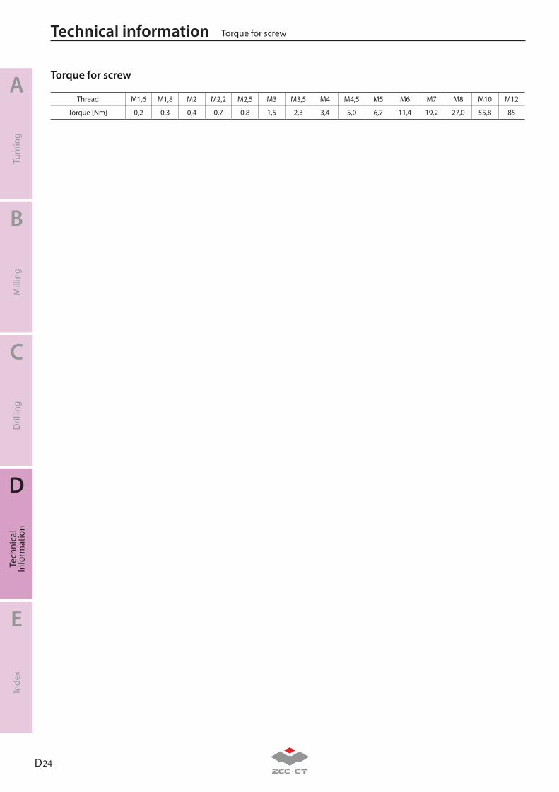
D 24
A
B
C
D
E
Turn
ing
Mill
ing
Dril
ling
Tech
nica
lIn
form
atio
nIn
dex
Technical information
Torque for screw
Thread M1,6 M1,8 M2 M2,2 M2,5 M3 M3,5 M4 M4,5 M5 M6 M7 M8 M10 M12
Torque [Nm] 0,2 0,3 0,4 0,7 0,8 1,5 2,3 3,4 5,0 6,7 11,4 19,2 27,0 55,8 85
Torque for screw
E 1
A
B
C
D
E
Turn
ing
Mill
ing
Dril
ling
Inde
xTe
chni
cal
Info
rmat
ion
Index
Inserts E2-E5
Tools E6-E8 E
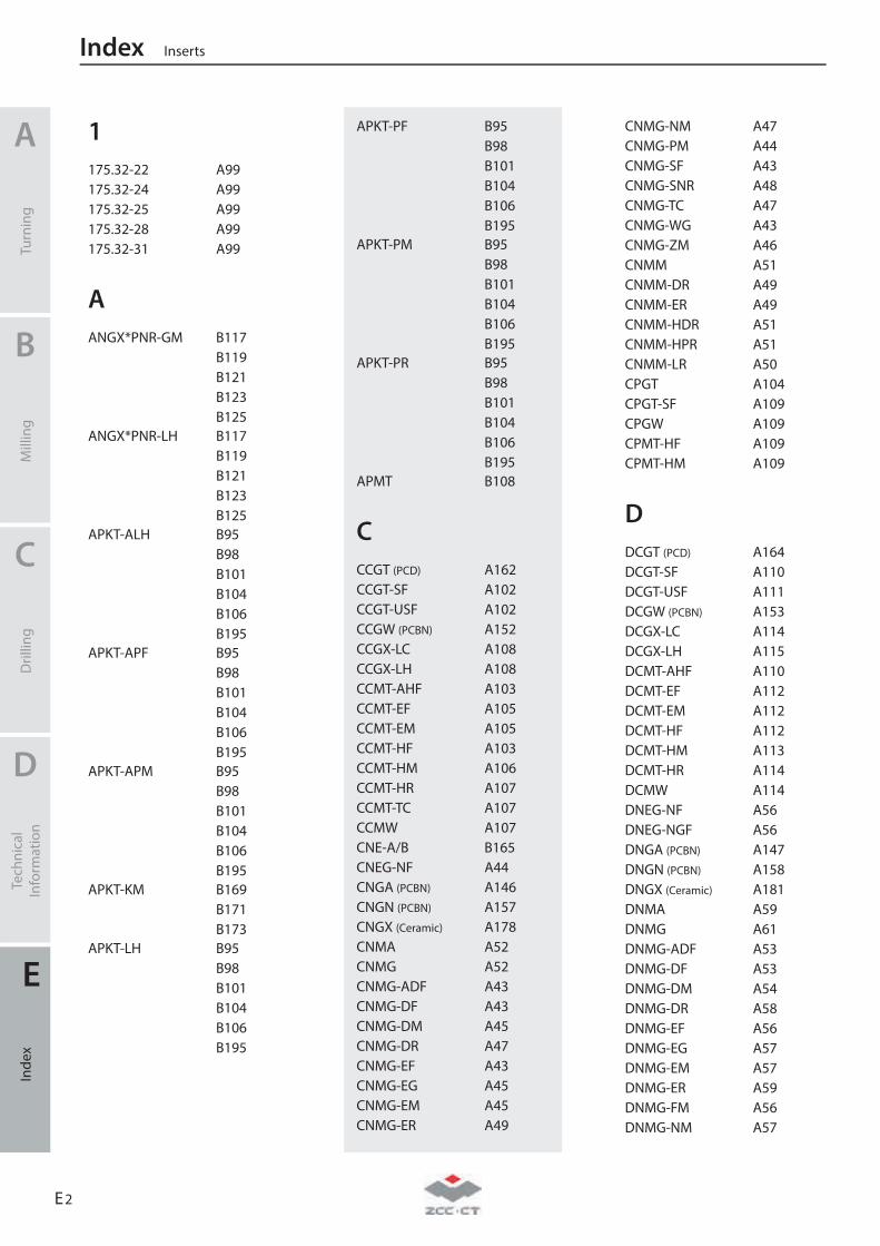
1 175.32-22 A99 175.32-24 A99 175.32-25 A99 175.32-28 A99 175.32-31 A99
A ANGX*PNR-GM B117
B119B121B123B125
ANGX*PNR-LH B117B119B121B123B125
APKT-ALH B95B98B101B104B106B195
APKT-APF B95B98B101B104B106B195
APKT-APM B95B98B101B104B106B195
APKT-KM B169B171B173
APKT-LH B95B98B101B104B106B195
Index Inserts
A
Turn
ing
B
Mill
ing
C
Dril
ling
D
Tech
nica
l In
form
atio
n
E
Inde
x
E 2
APKT-PF B95B98B101B104B106B195
APKT-PM B95B98B101B104B106B195
APKT-PR B95B98B101B104B106B195
APMT B108
C CCGT (PCD) A162 CCGT-SF A102 CCGT-USF A102 CCGW (PCBN) A152 CCGX-LC A108 CCGX-LH A108 CCMT-AHF A103 CCMT-EF A105 CCMT-EM A105 CCMT-HF A103 CCMT-HM A106 CCMT-HR A107 CCMT-TC A107 CCMW A107 CNE-A/B B165 CNEG-NF A44 CNGA (PCBN) A146 CNGN (PCBN) A157 CNGX (Ceramic) A178 CNMA A52 CNMG A52 CNMG-ADF A43 CNMG-DF A43 CNMG-DM A45 CNMG-DR A47 CNMG-EF A43 CNMG-EG A45 CNMG-EM A45 CNMG-ER A49
CNMG-NM A47 CNMG-PM A44 CNMG-SF A43 CNMG-SNR A48 CNMG-TC A47 CNMG-WG A43 CNMG-ZM A46 CNMM A51 CNMM-DR A49 CNMM-ER A49 CNMM-HDR A51 CNMM-HPR A51 CNMM-LR A50 CPGT A104 CPGT-SF A109 CPGW A109 CPMT-HF A109 CPMT-HM A109
D DCGT (PCD) A164 DCGT-SF A110 DCGT-USF A111 DCGW (PCBN) A153 DCGX-LC A114 DCGX-LH A115 DCMT-AHF A110 DCMT-EF A112 DCMT-EM A112 DCMT-HF A112 DCMT-HM A113 DCMT-HR A114 DCMW A114 DNEG-NF A56 DNEG-NGF A56 DNGA (PCBN) A147 DNGN (PCBN) A158 DNGX (Ceramic) A181 DNMA A59 DNMG A61 DNMG-ADF A53 DNMG-DF A53 DNMG-DM A54 DNMG-DR A58 DNMG-EF A56 DNMG-EG A57 DNMG-EM A57 DNMG-ER A59 DNMG-FM A56 DNMG-NM A57
DNMG-PM A54 DNMG-SF A53 DNMG-SNR A58 DNMG-TC A57 DNMG-ZM A55 DNMM-DR A60 DNMM-ER A60 DNMM-HDR A60 DNMM-LR A60 DPGT-SF A116 DPGT-USF A116 DPMW A116
H HNEX-DF B63 HNEX-DM B63 HNEX-DR B63 HNGX-HDR B203 HNGX-MR B203
K KNUX A98
L LNCX B206 LNE32.302 B204 LNE32.534 B205 LNKT-GM B111
B113 LNKT-ZR B65
B73B80
M MPHT-DM B148
B150B167
O OFKR-DF B39 OFKR-DM B39 OFKR-LH B39 OFKT-DF B37 OFKT-DM B37
Inserts Index
A
Turn
ing
B
Mill
ing
C
Dril
ling
D
Tech
nica
l In
form
atio
n
E
Inde
x
E 3
OFKT-LH B37 ONHU-GM B53 ONHU-PF B43
B45 ONHU-PM B43
B45 ONHU-W B43
B46
P PNEG-CF B57
B60 PNEG-CM B57
B60 PNEG-CR B57
B60 PNEG-PF B58
B60 PNEG-PM B58
B60 PNEG-PR B58
B60
Q QC**R/L A367
QC**R/L***R A370
R R/LT****N-A(G) A413 R/LT****N-A(G)B A430 R/LT****N-AC A424 R/LT****N-AP A426 R/LT****N-BPTB A435 R/LT****N-BSPT A417 R/LT****N-BSPTB A434 R/LT****N-BUT A428 R/LT****N-GM A411 R/LT****N-GMB A429 R/LT****N-NPT A418 R/LT****N-NPTF A419 R/LT****N-R A420 R/LT****N-RT A427 R/LT****N-STAC A425 R/LT****N-TR A423 R/LT****N-UN A416 R/LT****N-UNB A433 R/LT****N-W A415
R/LT****N-WB A432 R/LT****W-A(G) A413 R/LT****W-A(G)B A430 R/LT****W-AC A424 R/LT****W-AP A426 R/LT****W-BPTB A435 R/LT****W-BSPT A417 R/LT****W-BSPTB A434 R/LT****W-BUT A428 R/LT****W-GM A411 R/LT****W-GMB A429 R/LT****W-MJ A421 R/LT****W-NPT A418 R/LT****W-NPTF A419 R/LT****W-R A420 R/LT****W-RT A427 R/LT****W-STAC A425 R/LT****W-TR A423 R/LT****W-UN A416 R/LT****W-UNB A433 R/LT****W-UNJ A422 R/LT****W-W A415 R/LT****W-WB A432 RCGT A117 RCGX-LH A117
B82B84
RCKT-DM B82B85
RCKT-DR B82B85
RCKT-ER B82B85
RCKT-NM B82B85
RCMT A117 RCMW (PCBN) B85 RCMX A118 RDKW B89
B93B198B200
RNGN (PCBN) A161 RNMG A97 ROHX B130
S SCGX-LC A121 SCGX-LH A122 SCMT A121 SCMT-AHF A119
SCMT-EF A119 SCMT-EM A119 SCMT-HF A120 SCMT-HM A120 SCMT-HR A121 SDMT B128 SDMT-DM B157
B159B191
SDMT-PM B157B159B191
SEEN B34 SEET-CF B28
B31 SEET-CM B28
B31 SEET-CR B28
B31 SEET-DF B28
B31 SEET-DM B28
B31 SEET-DR B28
B31 SEET-EF B28
B31 SEET-EM B28
B31 SEET-LH B28
B31 SEET-PF B78 SEET-PM B78 SEET-PR B78 SEET-W B29
B32 SEKN B35 SEKR B35 SNEG-E B49 SNEG-GM B49 SNEG-GR B49 SNEG-W B50 SNGA (PCBN) A148 SNGN (PCBN) A159 SNGX (Ceramic) A183 SNKN B207 SNMA A74 SNMG A73 SNMG-ADF A62 SNMG-DF A62 SNMG-DM A65 SNMG-DR A67
Index Inserts
A
Turn
ing
B
Mill
ing
C
Dril
ling
D
Tech
nica
l In
form
atio
n
E
Inde
x
E 4
SNMG-EF A63 SNMG-EG A65 SNMG-EM A66 SNMG-ER A68 SNMG-NM A67 SNMG-PM A64 SNMG-SF A62 SNMG-TC A66 SNMM A73 SNMM-DR A69 SNMM-HDR A71 SNMM-HPR A72 SNMM-LR A70 SNUN A76 SPAN B208 SPCN B208 SPEX-1 B71 SPGN B211 SPGT-EM C19 SPGT-PM C19 SPKN B58
B70 SPKR B71 SPKR-GM B71 SPKT B67 SPKW B67 SPMR B209 SPMT B128
B175B177B179B181B183B185
SPMT-HT B210 SPMT-KM B169
B171B173
SPMT-KT B210 SPMT-PM B169
B171B173
SPMW A123 SPUN B211
T TBGH A124 TCGT (PCD) A166 TCGT-SF A125 TCGT-USF A125
TCGW (PCBN) A154 TCGX-LC A130 TCGX-LH A130 TCMT A129 TCMT-AHF A126 TCMT-EF A127 TCMT-EM A127 TCMT-HF A126 TCMT-HM A128 TCMT-HR A128 TCMW A128 TNGA (PCBN) A149 TNGN (Ceramic) A186 TNMA A87 TNMG A86 TNMG-ADF A77 TNMG-DF A77 TNMG-DM A80 TNMG-DR A83 TNMG-EF A79 TNMG-EG A82 TNMG-EM A82 TNMG-ER A84 TNMG-FM A79 TNMG-PM A80 TNMG-SF A78 TNMG-TC A82 TNMG-ZM A81 TNMM A87 TNMM-DR A84 TNMM-HDR A85 TNMM-LR A84 TNMX A100 TNMX-WG A77 TPAN B212 TPCN B212 TPGH A131 TPGT-SF A131 TPKN B75
B213 TPMR B214 TPUN B214
V VBET-NF A138 VBET-NGF A140 VBGT (PCD) A168 VBGT-HR A140 VBGT-SF A139 VBGW (PCBN) A155
VBMT-AHF A138 VBMT-EF A138 VBMT-EM A140 VBMT-HF A138 VBMT-HM A140 VBMT-HR A141 VBMT-SNR A141 VBMW A141 VCGT A133 VCGT-HF A132 VCGT-NF A132 VCGT-SF A132 VCGT-USF A133 VCGW (PCBN) A156 VCGX-LC A134 VCGX-LH A135 VCMT-EF A136 VCMT-EM A136 VNEG-NF A88 VNEG-NGF A89 VNGA (PCBN) A150 VNMG A90 VNMG-ADF A88 VNMG-DF A88 VNMG-DM A90 VNMG-EF A88 VNMG-EM A90 VNMG-NM A90 VNMG-SF A89 VNMG-TC A91 VNMG-ZM A91 VPGT-USF A137
W WCMX-53 A142
C20 WCMX-D C20 WCMX-PG C20 WNEG-NF A93 WNGA (PCBN) A151 WNGN (PCBN) A160 WNMA A96 WNMG-ADF A92 WNMG-DF A92 WNMG-DM A94 WNMG-DR A96 WNMG-EF A93 WNMG-EG A94 WNMG-EM A94 WNMG-NF A93
Inserts Index
A
Turn
ing
B
Mill
ing
C
Dril
ling
D
Tech
nica
l In
form
atio
n
E
Inde
x
E 5
WNMG-NM A96 WNMG-PM A95 WNMG-SF A92 WNMG-TC A96 WNMG-WG A93 WNMG-ZM A95 WPGT B161
B163B193
WPGT-PM B161B163B193
X XPHT-GM B132
B134B136B138B189
XSEQ B144B146
Y YNMX A101 YNUX A101
Z ZDET B127 ZDET-PM B127 ZIGQ-NM A363 ZILD-LC A365 ZIMF-NM A362 ZOHX-GF B140
B142B202
ZOHX-GM B140B142B202
ZP*D-MG-R/L A354 ZP*S-MG A353 ZPD-MG A352 ZPNT B127 ZR*D-EG A361 ZR*D-LH A364 ZR*D-MG A360 ZT*D-EG A357 ZT*D-MG A355
ZT*D-MM A351 ZT*S-MG A356
1 1101SC05 C110 1105SC03 C107 1143SC120 C120 1143SC90 C119 1165PA03 C112 1534SH03 C106 1534SP03C C87 1534ST03C C92 1534SU03 C30 1534SU03C C30 1536ST05C C96 1536SU05 C41 1536SU05C C41 1538SU08C C51 1557SU03 C70 1576PC05 C116 1576PC05C C116 1579PC15C C118 1588SL10C C72 1588SL12C C75 1588SL15C C79 1588SL20C C82 1588SL30C C85 1634SU03C C54 1636ST05C C100 1636SU05C C58 1734SU03C C62 1736SU05C C66
3 3101H7 C131 3102H7 C132 3103H7 C134 3112H7 C133
4 4111 C159 4122A C145 4122M C148 4201A C155 4201C C151 4202A C157 4202C C153 4222A C146 4222M C149
Index Tools
A
Turn
ing
B
Mill
ing
C
Dril
ling
D
Tech
nica
l In
form
atio
n
E
Inde
x
E 6
5 5501/5601 B418 5501R302GM B262 5501R303GM B278 5501R304GF B292 5501R38414GM B394 5502R302GM B264 5502R303GM B280 5502R304GF B294 5502R38414GM B395 5502R38414GM-R B398 5502R402NM B368 5502R453GM B282 5502R55MHH B352 5508R454GM B296 5565R302GF B301 5565R302NH B385 5566R302GF B303 5566R302NH B386 5589R45MGFR02 B298 5601 B420 5601R302GM B263 5601R303GM B279 5601R304GF B293 5601R38414GM B396 5602R302GM B266 5602R303GM B281 5602R303GR B315 5602R304GF B295 5602R304GR B316 5602R305GR B317 5602R38414GM B397 5602R38414GM-R B399 5602R453GM B283 5602R454GM B297 5665R202GM B302
A A***-PCLNR/L A284 A***-PDSNR/L A286 A***-PDUNR/L A287 A***-PSKNR/L A289 A***-PTFNR/L A290 A***-SCLCR/L A293 A***-SDQCR/L A295 A***-SDUCR/L A296 A***-SDZCR/L A297 A***-SSKCR/L A298 A***-STFCR/L A300
A***-SVQBR/L A304 A***-SVUBR/L A305 AL-2B B387 AL-2E B376 AL-2EL B377 AL-2R-AIR B388 AL-2RL-AIR B389 AL-3E B379 AL-3EL B380 AL-3R-AIR B391 AL-3RL-AIR B392 AL-3W B384 ALG-2E B378 ALG-2R B390 ALG-3E B381 ALP-3E B382 ALP-4E B383
B BMR01 B126 BMR02 B129 BMR03 B131 BMR04 B139
C C***-SCLPR/L A312 C***-SDQPR/L A314 C***-SDUPR/L A316 C***-STUPR/L A318 C***-SVQCR/L A321 C***-SVUCR/L A322 C40X-Q*DR/L A394 CCLNR/L A258 CDJNR/L A260 CKJNR/L A256 CKNNR/L A257 CMA01 B178 CMD01 B182 CMZ01 B174 CRDNN A264 CSDNN A265 CSKNR/L A262 CSRNR/L A263 CTJNR/L A259 CTUNR/L A261
D DCLNR/L A197 DDJNR/L A198 DSBNR/L A199 DTGNR/L A200 DVJNR/L A202 DVVNN A201 DWLNR/L A203
E E***-SCLCR/L A313 E***-SCLPR/L A312 E***-SDQCR/L A315 E***-SDUCR/L A317 E***-STFCR/L A319 E***-STFPR/L A320 E***-SVUCR/L A322 EMP01 B94 EMP02 B100 EMP03 B103 EMP04 B105 EMP05 B107 EMP09 B110 EMP13 B116
F FMA01 B27 FMA02 B30 FMA03 B33 FMA04 B36 FMA07 B44 FMA11 B48 FMA12 B52 FMD02 B56 FMD03 B64 FME02 B66 FME03 B68 FME04 B72 FMP01 B74 FMP02 B76 FMP03 B79 FMR01 B81 FMR02 B83 FMR03 B86 FMR04 B90
Tools Index
A
Turn
ing
B
Mill
ing
C
Dril
ling
D
Tech
nica
l In
form
atio
n
E
Inde
x
E 7
G GM-2B B304 GM-2BFP B306 GM-2BL B305 GM-2BP B308 GM-2BS B307 GM-2E B267 GM-2EFP B270 GM-2EL B268 GM-2EP B273 GM-2ES B275 GM-2EX B269 GM-2F B271 GM-2FL B272 GM-2R B312 GM-3E B276 GM-3EL B277 GM-4B B310 GM-4BL B311 GM-4E B288 GM-4E-G B289 GM-4EFP B291 GM-4EL B290 GM-4EL-G B285 GM-4EX-G B287 GM-4F-G B284 GM-4FL-G B286 GM-4R B313 GM-4RL B314 GM-4W B318 GM-6E B299 GM-6EL B300 GQC**R/L A397
H HM-2B B355 HM-2BFP B357 HM-2BL B356 HM-2BP B359 HM-2BS B358 HM-2E B344 HM-2EFP B345 HM-2EP B346 HM-2ES B348 HM-4B B361 HM-4BL B362 HM-4E B349 HM-4EFP B351 HM-4EL B350
HM-4R B363 HM-4RF B364 HM-4RP B365 HM-6E B353 HM-6EL B354 HMP01 B168 HMP01-EC B172
J JCLNR/L A266 JDJNR/L A267 JSDNN A268
M MCBNR/L A218 MCLNR/L A219 MDJNR/L A220 MDPNN A221 MRDNN A233 MRGNR/L A234 MSBNR/L A222 MSDNN A225 MSKNR/L A224 MSRNR/L A223 MTFNR/L A229 MTGNR/L A226 MTJNR/L A227 MVJNR/L A231 MVVNN A230 MWLNR/L A232
N NM-2B B372 NM-2BP B373 NM-2E B369 NM-2EP B370 NM-4E B371
P PCBNR/L A204 PCLNR/L A205 PDJNR/L A206 PDNNR/L A207 PM-2B B329 PM-2BC B332 PM-2BFP B331
PM-2BL B330 PM-2E B320 PM-2EL B321 PM-2R B337 PM-4B B335 PM-4BL B336 PM-4E B325 PM-4E-G B322 PM-4EL B326 PM-4EL-G B323 PM-4EX-G B324 PM-4H B338 PM-4HL B339 PM-4R B340 PM-4RL B341 PM-6E B327 PM-6EL B328 PSBNR/L A208 PSDNN A210 PSKNR/L A211 PSSNR/L A212 PTFNR/L A213 PTGNR/L A215 PTTNR/L A214 PWLNR/L A217
Q Q*DR/L A395 QCH-APKT B194 QCH-RD B197 QCH-RDKW B199 QCH-SDMT B190 QCH-WPGT B192 QCH-XPHT B188 QCH-ZOHX B201 QE**R/L A376 QE*S**N A382 QE*SN30 A378 QE*SR/L A381 QEBDR/L A376 QECDR/L A379 QF**R/L A384 QF**RR/LL A386 QF*DRR/LL A390 QX**R/L A380 QZS* A383
Index Tools
A
Turn
ing
B
Mill
ing
C
Dril
ling
D
Tech
nica
l In
form
atio
n
E
Inde
x
E 8
S S***-PCLNR/L A284 S***-PDSNR/L A286 S***-PDUNR/L A287 S***-PSKNR/L A289 S***-PTFNR/L A290 S***-PWLNR/L A291 S***-SCFCR/L A310 S***-SCLCR A311 S***-SCLCR/L A293 S***-SCLPR/L A306 S***-SDQCR/L A295 S***-SDQPR/L A307 S***-SDUCR/L A296 S***-SDUPR/L A308 S***-SDZCR/L A297 S***-SSKCR/L A298 S***-STFCR/L A300 S***-STUPR/L A309 S***-SVQBR/L A304 S***-SVQCR/L A302 S***-SVUBR/L A305 S***-SVUCR/L A303 S*K-QC**R/L A398 SCACR/L A235 SCACR/L-SC A272 SCLCR/L A236 SCLCR/L-SC A273 SDACR/L A237 SDACR/L-SC A274 SDHCR/L-SC A275 SDJCR/L A238 SDJCR/L-SC A276 SDNCN A239 SDNCN-SC A277 SMP01 B143 SMP03 B147 SMP05 B151 SNL A440 SNR A439 SRDCN A254 SRGCR/L A255 SSBCR/L A245 SSDCN A246 SSKCR/L A247 SSSCR/L A248 STACR/L A249 STFCR/L A250 STGCR/L A251 STTCR/L A252
SVABR/L A241 SVACR/L-SC A278 SVJBR/L A240 SVJCR/L A244 SVJCR/L-SC A279 SVVBN A242 SVVCN A243 SWACR/L A253 SWL A438 SWR A437
T TMP01 B166
U UM-4E B402 UM-4E-W B403 UM-4EFP B407 UM-4EL B404 UM-4EL-W B405 UM-4ELP-W B406 UM-4R B408 UM-4RFP B410 UM-4RL B409
V VSM-4E B412 VSM-4E-C B413 VSM-4R B414
X XMP01 B164 XMR01 B158
Z ZD03 C16 ZTD02 C8 ZTD03 C10 ZTD04 C12 ZTD05 C14
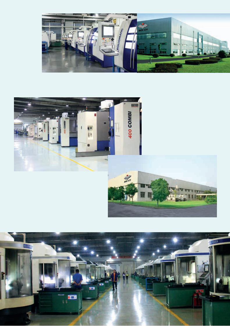

Detroit (USA)Düsseldorf (Germany / Europe)
Zhuzhou (China)
Certificate of RegistrationQUALITY MANAGEMENT SYSTEM - ISO 9001:2008
This is to certify that: ZCC Cutting Tools EuropeGmbHHeltorfer Straße 12Düsseldorf40472Germany
Holds Certificate No: FS 651501and operates a Quality Management System which complies with the requirements of ISO 9001:2008 for thefollowing scope:
Distribution and Logistics for Metal Cutting Tools
For and on behalf of BSI:Peter U. E. Leveringhaus, Managing Director BSI Group Deutschland GmbH
Original Registration Date: 17/06/2010 Effective Date: 17/06/2016Latest Revision Date: 11/06/2016 Expiry Date: 14/09/2018
Page: 1 of 1
This certificate was issued electronically and remains the property of BSI and is bound by the conditions of contract.An electronic certificate can be authenticated online.Printed copies can be validated at www.bsi-global.com/ClientDirectory or telephone +49 (0)69 22 228 9200.
BSI Group Deutschland GmbH, Hanauer Landstraße 115, 60314 Frankfurt am Main.A Member of the BSI Group of Companies.
Zhuzhou Cemented Carbide Cutting Tools Co., Ltd. (ZCC-CT) is located in Zhuzhou, Hunan province, China and is the lar-gest supplier of carbide tools into the Chinese market. The ZCC-CT cutting tool company is part of the “Zhuzhou ce-mented carbide Group” who manufacture carbide materials and powders. Both of these companies are part of the “Min-metals Corporation” who mine and produce raw tungsten carbide materials.
Since its foundation in 1953 ZCC-CT has developed rapidly by progressively using highly advanced modern production technology as well as having a highly qualified and com-mitted workforce. With over 2,000 employees the company is now the largest producer of carbide cutting tools in China and one of the leading carbide manufacturers worldwide.
Using this advanced production technology, ZCC-CT pro-ducts are manufactured to the highest quality standards to maintain a constant quality and high performance. The wide range of products contains indexable carbide inserts (coated and uncoated), inserts of Cermets, CBN, PCD and ceramics, solid carbide cutting tools as well as tool holders and milling bodies. The products are produced to various international standards such as ISO DIN, ANSI, JIS and BSI. Furthermore customised and special carbide product are also offered.
Research and development plays a major and significant role at ZCC-CT. The production facilities use the most so-phisticated and advanced equipment available and this is supplied by the leading machine and equipment manufac-turers in Germany and Switzerland. A highly qualified and skilled team of engineers in the R&D departments are cons-tantly developing new and improved cutting tools. There is a constant desire to continually enhance the quality, to fulfill the ever increasing market requirements for new and initiative products and to achieve the best possible result for the customers.
The production and administration facilities in China are certified to ISO 9001:2000 and they maintain strict environ-mental management to ISO 14001:2004 standards.
Since 2003 ZCC Cutting Tools has operated a sales organi-sation in Europe. This sales and warehousing subsidiary of ZCC-CT is based in Düsseldorf (Germany) and has been pro-gressively build up and expanded by Mr. Quanliang Zhao the European Managing Director.
Sales to all European countries, as well as Russia and Tur-key, are controlled and managed from this European central warehouse in Düsseldorf, with the majority of the products being dispatched on the same day of ordering. The business operates under the quality management system for “Distri-bution and Logistics of Metal Cutting Tools” and is certified with DIN EN ISO 9001:2008.
ZCC Cutting Tools Europe has a constantly growing num-ber of employees covering sales, marketing, warehouse and distribution, technical support, IT, HR and accounting. Our external sales team and our partners from around Europe are there to support you on-site in your production facilities or distribution operations. Our internal, highly qualified, technical application engineering staff are always availa-ble to give the customer technical advice and support via telephone, by email or in person. The internal sales team takes care of your enquiries and orders and together with dedicated warehouse staff they ensure that products are dispatched to you as quickly as possible.
The complete team at ZCC Cutting Tools Europe are there to support you and be your competent and efficient partner in the global Cutting Tool Industry.
The Company
Sales center in Europe
ZCC Cutting Tools Europe GmbHwww.zccct-europe.comWanheimer Straße 57 40472 Düsseldorf, GermanyTel.: +49(0)211-989240-0 Fax: +49(0)211-989240-111E-mail: [email protected]
700
/ CAT
/ V2
018
/ 10.
0 / 1
1.17
© Copyright by ZCC Cutting Tools Europe GmbH All rights reserved.
Sales center in France
ZCC Cutting Tools France S.A.S.www.zccct-europe.com14, Allée Charles Pathé, 18000 Bourges, FranceTel.: +33 (0)2-454101-40Fax: +33 (0)2-486619-46E-mail: [email protected]