
Welcome to Titan Tips by Bob Allevo - Starhoo · Titan Tips Latest Revision: April 28, 2012 2 Note:...
50
Titan Tips Latest Revision: April 28, 2012 1 Welcome to Titan Tips by Bob Allevo (Adapted from HTML to PDF by Mike Renzi) Table of Contents 1 Overview ......................................................................................................................................... 2 1.1 On with Bob's original pages! ................................................................................................... 2 2 How to Assemble your Titan ............................................................................................................ 3 3 Worm Clearance & Adjustment ....................................................................................................... 5 3.1 Jeff LunglHoffer's Quick List of Worm Adjustments .................................................................. 6 3.2 Mike Renzi's Tips on Worm Adjustment ................................................................................... 8 3.2.1 Worm Hex Bolts ............................................................................................................... 8 3.2.2 DEC Worm Tuning .......................................................................................................... 10 3.2.3 Slew/Goto Speed ............................................................................................................ 11 3.2.4 RA Worm Tuning ............................................................................................................ 11 4 Balancing your GEM....................................................................................................................... 11 4.1 So now, let's get into balancing..... ......................................................................................... 13 4.2 Now for the Ra axis....... ......................................................................................................... 18 5 Balancing Update - Sept. 24, 2004.................................................................................................. 19 6 Unbalance to Load the Worm ........................................................................................................ 19 7 Gearbox ......................................................................................................................................... 20 8 Clutch Operation ........................................................................................................................... 25 9 Re-Greasing the Titan DEC Assembly by Robert Anderson (tips and edited by Scott Oates) ............ 27 10 Worm Lubrication ...................................................................................................................... 33 11 Wire Management ..................................................................................................................... 36 12 Power Supply & More Horsepower ............................................................................................ 37 12.1 2.1.4 Power Requirements ..................................................................................................... 37 13 Miscellaneous Tips ..................................................................................................................... 38 14 MY OBSERVATORY - Bob Allevo.................................................................................................. 40 15 Titan Tracking Example .............................................................................................................. 44 16 Some Knowledgeable, Helpful, Titanites .................................................................................... 45 17 Appendix A - Drift Alignment Notes............................................................................................ 46 18 Appendix B: Titan 50 Gear Pics ................................................................................................... 47
Transcript of Welcome to Titan Tips by Bob Allevo - Starhoo · Titan Tips Latest Revision: April 28, 2012 2 Note:...

Titan Tips Latest Revision: April 28, 2012 1
Welcome to Titan Tips by Bob Allevo (Adapted from HTML to PDF by Mike Renzi)
Table of Contents
1 Overview ......................................................................................................................................... 2 1.1 On with Bob's original pages! ................................................................................................... 2
2 How to Assemble your Titan ............................................................................................................ 3 3 Worm Clearance & Adjustment ....................................................................................................... 5
3.1 Jeff LunglHoffer's Quick List of Worm Adjustments .................................................................. 6 3.2 Mike Renzi's Tips on Worm Adjustment ................................................................................... 8
3.2.1 Worm Hex Bolts ............................................................................................................... 8
3.2.2 DEC Worm Tuning .......................................................................................................... 10
3.2.3 Slew/Goto Speed ............................................................................................................ 11
3.2.4 RA Worm Tuning ............................................................................................................ 11
4 Balancing your GEM ....................................................................................................................... 11 4.1 So now, let's get into balancing..... ......................................................................................... 13 4.2 Now for the Ra axis....... ......................................................................................................... 18
5 Balancing Update - Sept. 24, 2004.................................................................................................. 19 6 Unbalance to Load the Worm ........................................................................................................ 19 7 Gearbox ......................................................................................................................................... 20 8 Clutch Operation ........................................................................................................................... 25 9 Re-Greasing the Titan DEC Assembly by Robert Anderson (tips and edited by Scott Oates) ............ 27 10 Worm Lubrication ...................................................................................................................... 33 11 Wire Management ..................................................................................................................... 36 12 Power Supply & More Horsepower ............................................................................................ 37
12.1 2.1.4 Power Requirements ..................................................................................................... 37 13 Miscellaneous Tips ..................................................................................................................... 38 14 MY OBSERVATORY - Bob Allevo .................................................................................................. 40 15 Titan Tracking Example .............................................................................................................. 44 16 Some Knowledgeable, Helpful, Titanites .................................................................................... 45 17 Appendix A - Drift Alignment Notes............................................................................................ 46 18 Appendix B: Titan 50 Gear Pics ................................................................................................... 47

Titan Tips Latest Revision: April 28, 2012 2
Note: On his web site Bob suggests that his Titan Tips should be made into a PDF document. I agree. I had a little time on my hands waiting for my own Titan mount to be completed, so here is a PDF version of his Titan Tips. At some point I would like to give this document a minor restructuring – keeping all the content but breaking it up into more digestable chunks in certain places. There is a wealth of information that Bob and others have collected. It deserves to be presented in the best light, and in that regard I hope people find this a help.
It seems that given the scarcity of documentation on the Titan, this PDF may evolve into the Titan owner's manual. If so, I'm happy to help keep it up to date. I will upload the latest version onto the TitanYahoo groups as well as here:
http://www.moonfolk.com/TitanTipsByBobAllevo.pdf
For the original web version of these tips, see: http://www.nightskyphotography.com/titan_tips.
- Mike Renzi (www.starhoo.com).
1 Overview This information was originally written and maintained by Bob Allevo and is re-posted here with Bob's
permission. The thanks of many a Losmandy Titan owner goes out to Bob for permitting us to continue
using these valuable materials! Thanks Bob!!!!
1.1 On with Bob's original pages! My name is Bob Allevo. I live in rural CT. and find astro-imaging a challenging hobby. I am very lucky to
have such a supportive wife.
I received my HGM Titan on June 2, 2004.....and I was very impressed first with its sheer size and also
how impressive it just plain looks. I still am. Also, the look of quality of the components is outstanding as
well as the packaging. I already had the Gemini manual, & email notes from
[email protected], [email protected], and several new acquaintances listed
below. As a result of these new connections, I had already purchased a high-power regulated power
supply and a voltage converter to up the ante for the servo motors, even before the Titan arrived. I had
also built a new, tiny observatory around my existing pier.
Now understand, this is my first German Equatorial Mount (GEM). I had been using fork mounted
Meade SCT's since 1985. So now terms like "meridian flip", "saddle", and others were just so unfamiliar
to me. You don't have that stuff with a fork mount. So my learning curve was steep. Maybe I'm forked.
But I am eager to learn and so I picked up some valuable information along the way and discovered that
many other new Titanites had the same questions. This is so true of so many products, etc. Sure, you can
search it out and eventually get most of what you are looking for. But several people have mentioned
that it would be real nice to be able to go somewhere and get a white paper for the information. This is
an attempt to provide it. It really should be put into an Adobe PDF document so it could reside in the
Titan files section and not on my personal web site. Some of the info is specific to the Titan yet there are
other tips, such as balancing a GEM, that apply to any GEM.
Believe me, I am not a know it all. Lot's of the info here has been passed along by my new friends. I just
felt like putting it together so someone else, such as a new Titanite, would have easy access to these

Titan Tips Latest Revision: April 28, 2012 3
tips. So many of the same questions keep getting asked over and over again. I too had my turn and I'm
not finished. Nor are these info pages. As I learn from experience or from the experience of others, I'll
try to add the info.
I do not assume any responsibility for any problems you encounter by trying any of these tips. Do them
at your own risk.
So let's begin......... Back To Top
2 How to Assemble your Titan Note: During assembly, be certain that all mating surfaces are free from any foreign material that would
upset the interface. Keep everything CLEAN.
1. Place the mount adapter, usually Losmandy # MAL onto the tripod or pier with the brackets
facing north. The brackets will ultimately hold the Gemini computer and will determine the
position of the Ra motor wire. Ref: the adapter has six equally spaced holes around the outside
diameter which will be used to fasten the Ra assembly. The Ra assembly can be rotated in the
adapter in 60 degree increments. Install six bolts (your supply) in the bottom of the adapter to
fasten it. Tighten these bolts securely. Note: If attaching to a pier, the mounting surface of the
pier should be level. The Ra assembly has two bubble levels that should read "level" when
placed onto the adapter. Some means of adjusting the adapter to pier mounting may be
required at this time.
2. Place the Ra assembly into the adapter such that the Ra axis is pointing north. Fasten with six
supplied button head screws with the plastic washers under the head of the screws. The Ra
assembly has a diameter that fits inside of the adapter and a shoulder that sits on top of the
adapter. When tightening the six screws, make sure the Ra head sits bottomed out on the
shoulder. Do this by pushing down on the Ra head as you tighten the screws. Tighten these
screws securely. Once done, verify that the two bubble levels read level. This is necessary when
mounting onto a pier, whereas a tripod can be adjusted in the field to level the bubbles. The
reason for having these bubbles read level is so that when aligning to the pole, an altitude
adjustment doesn't affect azimuth, or an azimuth adjustment doesn't affect the altitude
adjustment. It makes life much easier but it is not critical.
3. Attach one of the two identical worm blocks to the Ra head using two supplied socket head
screws with steel washers under the heads. Just snug these screws while pushing the worm
block towards the center of the Ra axis so that the worm engages the gear.
4. Roughly adjust the Ra elevation adjustment to your latitude. Graduated latitude indications are
located on the side. Do it now. If you run out of adjustment before reaching your latitude, it will
be necessary to re-index the elevation adjustment mechanism. You do not want the added
weight of the Dec assembly when making this adjustment. Re-index by removing three socket
screws located on each side of the Ra head in deep counter bored holes. Take note of how deep
the head is before you remove them. When you re-install the screws, it will be a guide for you. If
Titan Tips Latest Revision: April 28, 2012 4
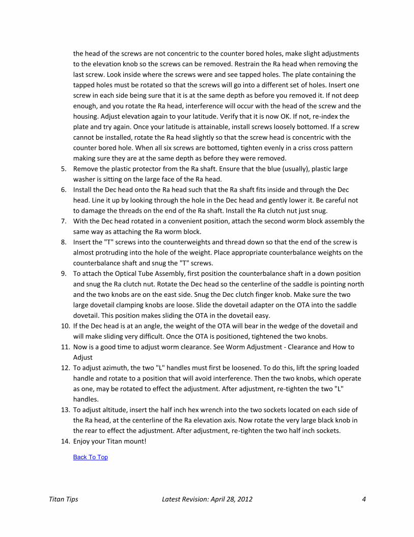
the head of the screws are not concentric to the counter bored holes, make slight adjustments
to the elevation knob so the screws can be removed. Restrain the Ra head when removing the
last screw. Look inside where the screws were and see tapped holes. The plate containing the
tapped holes must be rotated so that the screws will go into a different set of holes. Insert one
screw in each side being sure that it is at the same depth as before you removed it. If not deep
enough, and you rotate the Ra head, interference will occur with the head of the screw and the
housing. Adjust elevation again to your latitude. Verify that it is now OK. If not, re-index the
plate and try again. Once your latitude is attainable, install screws loosely bottomed. If a screw
cannot be installed, rotate the Ra head slightly so that the screw head is concentric with the
counter bored hole. When all six screws are bottomed, tighten evenly in a criss cross pattern
making sure they are at the same depth as before they were removed.
5. Remove the plastic protector from the Ra shaft. Ensure that the blue (usually), plastic large
washer is sitting on the large face of the Ra head.
6. Install the Dec head onto the Ra head such that the Ra shaft fits inside and through the Dec
head. Line it up by looking through the hole in the Dec head and gently lower it. Be careful not
to damage the threads on the end of the Ra shaft. Install the Ra clutch nut just snug.
7. With the Dec head rotated in a convenient position, attach the second worm block assembly the
same way as attaching the Ra worm block.
8. Insert the "T" screws into the counterweights and thread down so that the end of the screw is
almost protruding into the hole of the weight. Place appropriate counterbalance weights on the
counterbalance shaft and snug the "T" screws.
9. To attach the Optical Tube Assembly, first position the counterbalance shaft in a down position
and snug the Ra clutch nut. Rotate the Dec head so the centerline of the saddle is pointing north
and the two knobs are on the east side. Snug the Dec clutch finger knob. Make sure the two
large dovetail clamping knobs are loose. Slide the dovetail adapter on the OTA into the saddle
dovetail. This position makes sliding the OTA in the dovetail easy.
10. If the Dec head is at an angle, the weight of the OTA will bear in the wedge of the dovetail and
will make sliding very difficult. Once the OTA is positioned, tightened the two knobs.
11. Now is a good time to adjust worm clearance. See Worm Adjustment - Clearance and How to
Adjust
12. To adjust azimuth, the two "L" handles must first be loosened. To do this, lift the spring loaded
handle and rotate to a position that will avoid interference. Then the two knobs, which operate
as one, may be rotated to effect the adjustment. After adjustment, re-tighten the two "L"
handles.
13. To adjust altitude, insert the half inch hex wrench into the two sockets located on each side of
the Ra head, at the centerline of the Ra elevation axis. Now rotate the very large black knob in
the rear to effect the adjustment. After adjustment, re-tighten the two half inch sockets.
14. Enjoy your Titan mount!
Back To Top

Titan Tips Latest Revision: April 28, 2012 5
3 Worm Clearance & Adjustment
WORM CLEARANCE - This is a very hot topic. How much clearance? This is what has been gleaned from
much experience: "Loose is good". That may sound contrary to good guiding but it turns out that in
solving other annoyances, loosening the worm clearance actually improved tracking!
Here is what to do: With the clutch knob snug, grab the counter shaft and jiggle it, rock it back & forth
ever slightly. You WANT to be able to feel a slight clunking or hear it. If you don't, then you are too tight
and will stall a motor or even burn it. Get it to feel a little clunky. Do this by loosening the two socket
screws under the worm block and move the block in or out. Maintain the same clearance at each end of
the block with an automotive type feeler (see Fig.1). Snug each of the two wing adjusters which push
against the screws moving the worm into the gear. Do this slightly and maintain even feeler sizes at both
ends. The feeler size should be recorded. Later, you may want to loosen the clearance or tighten it a bit
and knowing what size you had set it to will enable you to make accurate adjustments if desired.
It may take a little self developed technique to do this adjustment efficiently. Snug the screws. Check for
the clunk. Redo if no clunk. As the night air cools, the worm clearance gets smaller so if you start out
without that clunk, you will end up with some binding due to interference between the worm and gear.
After the worms are adjusted, you should remove the motor and the small gearbox located on the end
of the worm block. This is very easy to do (See Gearbox). Now you can see a gear sticking out of the
worm box. Rotate the gear with your fingers so that the Ra or Dec axis makes a complete turn (360 deg).
It should turn easily all the way around, If you find a place that feels tight, you will need to loosen the
worm block some. This is the location where the clearance should be set. The reason that one particular
location is tighter than elsewhere is due to eccentricity. The gear form is slightly out of round or out of

Titan Tips Latest Revision: April 28, 2012 6
concentricity with the rotating axis. I did this rotation and found a snug place. So I increased the worm
clearance such that my feeler size was now .001 thicker than I previously had. Then I rotated the little
gear again for another complete turn (360 deg). No more snug place. Record the new feeler size. Using
the feeler this way provides a way to make accurate clearance adjustments and also to keep the worm
tangent to the gear and parallel to the opposing housing faces. (equal feeler size at both ends of worm
block)
Remember, as the temperature lowers, the clearance will decrease. If you set the clearance in a warmer
temperature than it will be when in use, allow for that and provide additional clearance.
If the clearance is not sufficient, the motor will heat up, stall, or even burn.
Apply this to both worms.
Back To Top
3.1 Jeff LunglHoffer's Quick List of Worm Adjustments (Copied from Jeff's post on [email protected], July 12, 2009).
Here's a quick list of the adjustments I've made to my Titan over the years. I've partly been lucky to get
such a great unit! But I was getting large jumps in the mount when I first purchased it, and it took some
tweaking to get from there to my current 5 arc seconds of total PE. Here's what I
focused:
1. Make sure your worm gears, particularly RA is well lubricated. Check out
http://www.nightskyphotography.com/titan_tips/WormLubrication.htm.
2. Try swapping your RA and DEC gears. My DEC gear was much better than my RA gear, so the
swap made a HUGE difference for me.
3. Experiment with different worm clearances. Buy TWO feeler gauge sets and use them to tweak
the spacing on the worm blocks.
Note that this is by far the trickiest adjustment to make.
When you tighten the worm gear bolts it TIGHTENS the clearance!
You quite literally have to use the feeler gauge like a washer. That's why you need two.
You slide one under both sides of the worm block, THEN tighten up the bolts. The
gauges will keep the block from getting too much tighter and should still wiggle out
(they will be tight!).
The clearance must not be too tight! You should feel the slightest little "click" when you
push/pull the counterweight shaft back and forth with the clutches snug. It should shift
a barely perceptible amount, but you can feel it.
Another way to tell if your clearance is good is to turn the spur gear by hand. Have a
look at Fig 7 here:
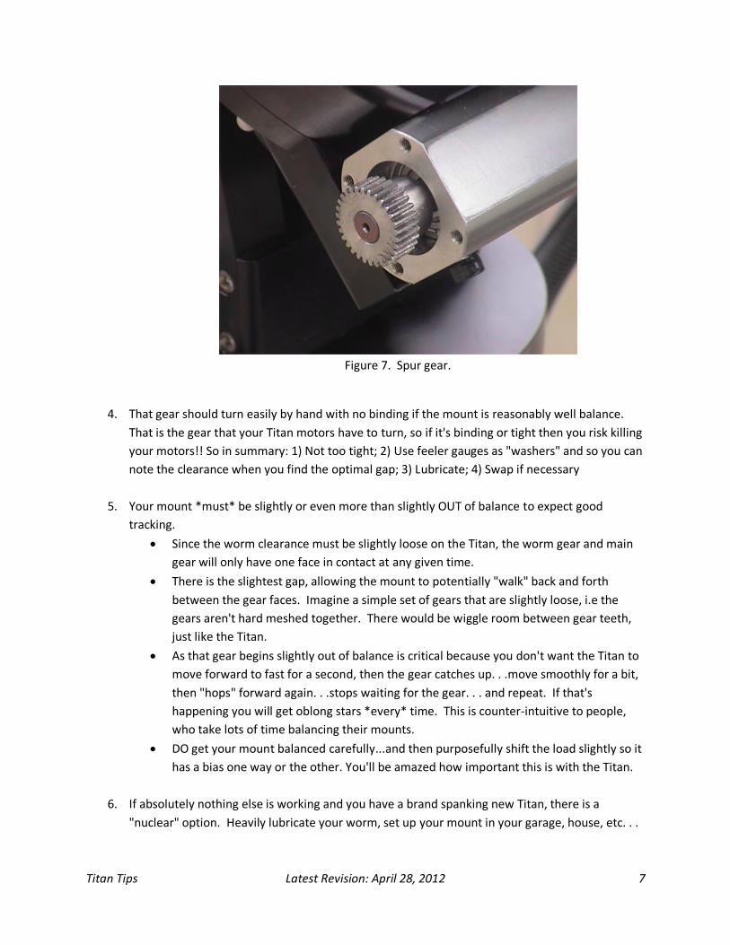
Titan Tips Latest Revision: April 28, 2012 7
Figure 7. Spur gear.
4. That gear should turn easily by hand with no binding if the mount is reasonably well balance.
That is the gear that your Titan motors have to turn, so if it's binding or tight then you risk killing
your motors!! So in summary: 1) Not too tight; 2) Use feeler gauges as "washers" and so you can
note the clearance when you find the optimal gap; 3) Lubricate; 4) Swap if necessary
5. Your mount *must* be slightly or even more than slightly OUT of balance to expect good
tracking.
Since the worm clearance must be slightly loose on the Titan, the worm gear and main
gear will only have one face in contact at any given time.
There is the slightest gap, allowing the mount to potentially "walk" back and forth
between the gear faces. Imagine a simple set of gears that are slightly loose, i.e the
gears aren't hard meshed together. There would be wiggle room between gear teeth,
just like the Titan.
As that gear begins slightly out of balance is critical because you don't want the Titan to
move forward to fast for a second, then the gear catches up. . .move smoothly for a bit,
then "hops" forward again. . .stops waiting for the gear. . . and repeat. If that's
happening you will get oblong stars *every* time. This is counter-intuitive to people,
who take lots of time balancing their mounts.
DO get your mount balanced carefully...and then purposefully shift the load slightly so it
has a bias one way or the other. You'll be amazed how important this is with the Titan.
6. If absolutely nothing else is working and you have a brand spanking new Titan, there is a
"nuclear" option. Heavily lubricate your worm, set up your mount in your garage, house, etc. . .

Titan Tips Latest Revision: April 28, 2012 8
then set up some automation software to slew your mount BACK and FORTH. . .for several
hours. . .a couple of things here. . .
a. Slow down the slew rate on the mount to like 400 at most (no need to whip things
around). . .
b. Monitor your motor temps for the first 10 minutes or so. You could use a trial version of
CCD Commander to do this for example. I can't stress again how important a and b are
above. Please don't blame me if you burn out your motors doing this. That said, you are
effectively lapping your gears and smoothing them out.
Think about it, if you have spurs or imperfections in your worm they will gradually get worn
down with use because when they make your mount "jump" they are getting knocked pretty
hard. I did this with my mount after all the adjustments and noticed that my PE went from
around 9 arc seconds peak to peak to 5 arc seconds peak to peak. Be sure to clean off the old
lube and re-lubricate the worm after you do this.
If folks were to work through these steps carefully with their Titan's I'm pretty sure it would resolve a lot
of the problems out there. . .NOW. . .whether a new owner of a $6000 mount should have to do all that
to get the best performance is another discussion altogether :) But honestly, if you dig through all of the
AP postings, etc. . .these kinds of problems aren't unheard of for mounts in *any* price range.
Back To Top
3.2 Mike Renzi's Tips on Worm Adjustment In this section, I'm sharing some tips that have helped me. I have spent a lot of time tuning both the RA
and DEC worm blocks on my mount so here are some experiences of mine that may be of help to others.
3.2.1 Worm Hex Bolts For both RA/DEC worm blocks...
Do not over tighten the two hex bolts that attach the worm to the mount. If they are
overly tight, they will contact the worm gear shaft, causing it to jam. There should be a
couple millimeters of space between the hex bolt and worm gear. In other words, if you
tighten them all the way until they stop, back off a few turns to the left.
Adjustments to tighten or loosen the worm gear should be done with the smaller, wing-
nut knobs.

Titan Tips Latest Revision: April 28, 2012 9
Diagram showing worm block to illustrate hex bolts and wingnut adjusters.

Titan Tips Latest Revision: April 28, 2012 10
3.2.2 DEC Worm Tuning The DEC worm block sits above the worm wheel. It is heavy, and you can actually rock it left and right as
it sits on the worm wheel. I have put a couple of shims under the worm block to "keep it still" as it sits
there. Ever since I did this, DEC autoguider corrections have been very good.
For the shims, I used two 8" zip ties and cut them down to about 1 1/2" (see photo below).
Two shims cut from 8" zip ties.

Titan Tips Latest Revision: April 28, 2012 11
DEC worm block. The shims slide into each end.
There may be a similar solution that improves on the zip tie shim, perhaps a washer - but I didn't want to
risk having a wash slide into the worm-wheel housing. Also, if I ever decide the shims are not quite
working very well, I can simply pull them out. So far, though, they've added stability in the way the DEC
worm block sits above the worm-wheel, minimized "clunk/slop" when reversing direction in DEC, and
much better response and corrections when autoguiding.
3.2.3 Slew/Goto Speed I think a Max slew/goto speed of 400 is desirable if your mount is carrying a lot of load. My mount is
carrying about 85 lbs. so I set the max speed at 400. This prevents binding/motor lags, and lets me get
away with a tighter (less slop) worm adjustment.
Also, with the DEC worm gear, if there is too much play, then you may experience problems with DEC
autoguider corrections (too much play, jerky corrections).
3.2.4 RA Worm Tuning In contrast to the DEC worm block, the RA worm block sits below the worm-wheel. So adjustments to
tighten/loosen the RA gear are a little easier since gravity - the weight of the RA block - keeps it fairly
evenly engaged with the worm-wheel.
Back To Top
4 Balancing your GEM BALANCE PRECISION - How well should the system be balanced? Probably several thoughts here. My
personal opinion is that it should be relatively close. But I don't think perfect balance is necessary. In

Titan Tips Latest Revision: April 28, 2012 12
fact, it is near impossible. Doing visual work and just changing an eyepiece, adding a barlow, rotating the
diagonal, or changing focus, will upset the balance from the "perfect" state. Besides, I feel a mount such
as the Titan should be tolerant of some unbalance. My opinion.
But it would be nice to have a basic understanding of how to balance well. It is up to the user to go to
the degree that will satisfy. Understanding this, there is no doubt that the most accurate way, whatever
that may be, would be done with the worm disengaged. That is so that it is not in contact with the gear.
In this condition, the mount can rotate freely on its bearings without any drag induced by the friction of
that large plastic washer that does impose some friction even when the mount is rotated with the clutch
knob loose. So when the worm is engaged and the clutch knob is loose, the mount cannot rotate on its
bearings with the motor off. So instead, it slips on the plastic washer. Things like surface finish,
coefficient of friction of the materials, etc. effect how much drag is present. I choose to balance with the
worm engaged. And I use a spring scale. It's a 4 lb scale with ounce graduations. See Fig.1
Figure 1.
The scale must be used at the angle of your latitude. I find it's use to be quite accurate. If I place a 2oz.
weight on the countershaft, I can see the difference from when it is not there. Also, I had the mount

Titan Tips Latest Revision: April 28, 2012 13
balanced from the day before and I was going to regrease the worms. When I disengaged the DEC, it did
not move! I was tickled.
4.1 So now, let's get into balancing..... The first axis to balance is the Dec. Rotate the Ra axis so that the counterweight shaft is level with the
ground and snug the Ra clutch. This puts the Dec axis parallel to the ground which puts it in it's freest
position. Now with the Dec worm engaged or disengaged, (your preference), you're ready to balance it.
All things that are to be used for the planned telescope session must be attached. It would be smart to
have your focus in the ballpark too since it involves moving a mirror, or the attachments by way of
focusing. So now you can slide the assembly in the saddle to get it balanced. I don't like this but it works.
Figure 2.
I'll continue this topic by showing the screw in the dovetail plate in Fig.2. It is against the saddle. That
means the Scope assembly cannot slide to the right in the image. I just did this for safety. So I do not
balance my Dec end by sliding the telescope in the saddle. It's heavy and seems so crude. And not easy
to move just a small amount to dial in a balanced condition.

Titan Tips Latest Revision: April 28, 2012 14
Figure 3.
In Fig.3 you can see a white colored disk. It is 2-part epoxy painted LEAD. It's attached to a Losmandy DA
adapter. I have several sizes of these weights but this one seems to work for everything. It's molded in a
coffee can and is about one inch thk. To balance the telescope assembly, that is with all hardware
attached, I simply slide the DA adapter along the length of the tube. This is very easy to do. The adapter
has a "T" bolt to tighten it in any location. The "T" bolt can just be seen at the bottom edge of the disk.
The disk is attached to the adapter with a stud and wing nut. It works great. It's shown in a forward
position. My camera, filter wheel, everything, is balanced from this single item. A side benefit is that it
also acts as a stop. Just like the screw on the other end. I have a second adapter that I did have right
against the saddle. Don't know why it isn't there now. I can see it in the background.
It seems that balancing the Dec with the worm engaged or not, sliding the assembly in the saddle or
sliding an alternative weight like I do should get the job done. This is not necessarily true. It has to do
with the center of gravity of the assembly. Lets say you have balanced to perfection. Now if you rotate in
Ra, does the Dec stay where it was? Probably not. But it should to be really balanced. After balancing,
you should be able to rotate any axis to any position without the Dec moving on its own. If it does, it's
due to the location of the center of gravity. Look at Fig. 4 It shows the balancing position

Titan Tips Latest Revision: April 28, 2012 15
Figure 4.
In the Top view you can see a green circle with a black vertical line through it. That represents the
location of the center of gravity. It is shown on a white line representing the Dec axis. It is on the Dec
axis because we balanced the Dec and by doing so, we put the C/G on the axis. We just didn't know it.
But look at the Front and Right side views. In those views, the C/G IS NOT on the Dec axis. We didn't
know this either. Now rotate in Ra and the image looks like Fig.5
Figure 5.
Titan Tips Latest Revision: April 28, 2012 16
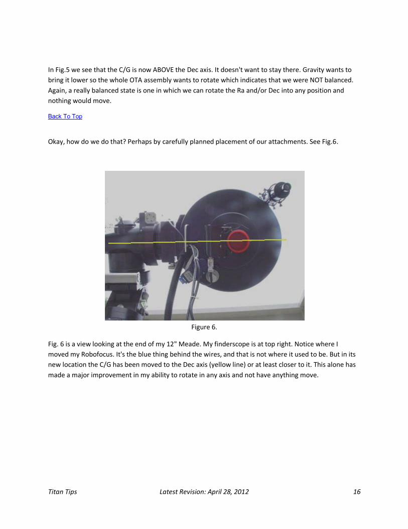
In Fig.5 we see that the C/G is now ABOVE the Dec axis. It doesn't want to stay there. Gravity wants to
bring it lower so the whole OTA assembly wants to rotate which indicates that we were NOT balanced.
Again, a really balanced state is one in which we can rotate the Ra and/or Dec into any position and
nothing would move.
Back To Top
Okay, how do we do that? Perhaps by carefully planned placement of our attachments. See Fig.6.
Figure 6.
Fig. 6 is a view looking at the end of my 12" Meade. My finderscope is at top right. Notice where I
moved my Robofocus. It's the blue thing behind the wires, and that is not where it used to be. But in its
new location the C/G has been moved to the Dec axis (yellow line) or at least closer to it. This alone has
made a major improvement in my ability to rotate in any axis and not have anything move.

Titan Tips Latest Revision: April 28, 2012 17
Figure 7.
See Fig.7 = The SBIG Adaptive Optics is mounted to the Optec focuser. The camera and filter wheel are
mounted to the AO, which places them off from the OTA centerline. That is a lot of offset weight which
throws the center of gravity way off. So I added a shortened ScopeStuff mounting rail to the Losmandy
adapter so the weight could be slid sideways as well as fore and aft. In that image you can see that the
weight is offset from the OTA centerline in the opposite direction of the camera. Fig. 8 shows a close-
up...
Figure8.

Titan Tips Latest Revision: April 28, 2012 18
4.2 Now for the Ra axis....... Back To Top
Again, worm engaged or not, is up to you. And again, more "near perfect balance" can be had with the
worm disengaged.
Figure 9.
There's more than meets the eye. First of all, all of that weight on the counterbalance shaft totals about
63lbs. That is what I need for my 12" Meade.
Where should it go? The pieces can be spread apart into different groups and spacing and still be able to
balance the telescope hardware. Well I have read on some forum that it should be choked up as far as
possible (to the right in Fig.9). The idea being that it causes the least amount of shaft flex. This makes
sense to me because the shaft is stiffer the shorter it's used length. If I moved the pair any more to the
right, the single one would not have any more room on the left for adjustment. This is picky but
probably smart for imaging.
Don't forget, the more accurately you get balanced at the start, the less you will depart from a balanced
state when you rotate your diagonal or whatever.
Also check the section Unbalance to Load the Worm
Back To Top

Titan Tips Latest Revision: April 28, 2012 19
5 Balancing Update - Sept. 24, 2004 As you may know, I dislike and do not remove or disengage my worm to balance. But I came up with
something that works just like a disengaged worm but in a small way. That small amount of worm to
gear clearance is the "small way". Here's what I do for each axis:
1. Rock the axis through it's clearance in one direction until the worm bottoms then let go.
2. Lightly push it in the same direction again. Does it go? If it does, the opposite end is heavy.
Adjust weight.
3. If it doesn't go then push in the opposite direction and let go.
4. Lightly push it in the same direction again. Does it go? If it does, the opposite end is heavy.
Adjust weight.
5. Repeat this with weight adjustment so that when pushed in one direction it stays there and
when pushed in the opposite direction it stays there as well.
I have done this and then removed the worm block to see if it truly is balanced. Well of course it is! This
is so cool. Give it a try. It works in any axis orientation.
Back To Top
6 Unbalance to Load the Worm UNBALANCE - On purpose? Yes! At least for me. Ever since I had a motored telescope, the general
consensus has been to put some weight in the east arm of a forked telescope and on the counterweight
shaft of a GEM when pointing to the east. I would guess that when pointing to the west you could take
the weight off of the counterweight shaft and add it to the OTA end. Right? Sort of.
Let's say you wanted to put 4oz. on the counterbalance shaft after you balanced the entire setup so as
to load the worm. Now, when you cross the meridian and take the 4oz. off, where you put it on the OTA
end makes a difference.
The torque created by the 4oz. is comprised of the 4oz. AND it's distance from the axis of rotation. So
when you move it to the OTA end, you will need to put it at the same distance from the axis. This is not
practical so you change the amount of weight such that it gives the same worm load. Another problem is
that you will very easily upset the Dec balance and load the Dec worm. This could be bad. But cheer up.
I thought a very easy way to load the Ra worm for pointing in the east and west.
Look at Fig.10....

Titan Tips Latest Revision: April 28, 2012 20
1. During balancing.
2. 4 oz. bags. Pointing east.
3. No bags.
Figure 10.
Here's how it works. Let's assume you want to load the worm with 4oz. of weight. When you balance
the Ra axis, include a bag containing 4oz. See left frame in Fig.1
So now the Ra is balanced and it does have that 4oz. hanging there. Now, when pointing East, add a
second bag of 4oz. See center frame in Fig.1. Now the worm is loaded with 4oz. and is pointing East.
So now we do a meridian flip and remove BOTH bags. Now the OTA end is heavier by 4oz. and so loads
the worm again by 4oz.
Something to be aware of is the fact that that when the counterbalance shaft is in a horizontal position
and you load it with say 4oz., as the mount rotates in Ra, the effective load imposed by the 4oz.
diminishes to the point that when the shaft is vertical, there is zero load applied.
Back To Top
7 Gearbox Gearbox removal and re-assembly is straightforward. It would be wise to have a small container to put
the small parts into as you proceed. The parts will stay clean and you won't lose them. First remove the
wire from the motor.

Titan Tips Latest Revision: April 28, 2012 21
Figure 1.
Then remove the 2 screws (Fig.1) from the motor while keeping a finger on the end of the motor. If you
don't, it may fall out!
Figure 2.
This is what the motor looks like on the hidden end.

Titan Tips Latest Revision: April 28, 2012 22
Figure 3.
Now the gearbox cover can be removed by removing the 2 visible screws (Fig.3). Again, retain the cover
with a finger while removing the screws.
Figure 4.
Now you can see the gearbox (Fig.4). It is retained by the 2 extension nuts. Pliers are needed to loosen
these. Go gently though so as not to mar the nuts.

Titan Tips Latest Revision: April 28, 2012 23
Figure 5.
Once removed, the gearbox can be gently wiggled and slipped off the 2 studs (Fig.5). The gearbox is
made from plastic so be careful!
Figure 6.
Remove the 4 screws retaining the adapter plate (Fig. 6) while retaining it with a finger.

Titan Tips Latest Revision: April 28, 2012 24
Figure 7.
Now the gear on the end of the worm is revealed (Fig.7). This is the gear that should be rotated many
many times by hand to rotate the Ra or Dec axis 360 deg. See Worm Clearance.
Reassembly is essentially done in reverse with a note of caution. But while the gearbox is off, rotate the
protruding gear to verify its freedom of movement. Very lightly lubricate the gear. See Worm
Lubrication.
Also, when assembling anything with multiple retention, assemble evenly, a little at a time. Work cross
pattern. For instance, if putting a wheel on your car, don't put on one lug and then torque the heck out
of it. Put them all on and bring them down in the criss cross alternating pattern. This applies to anything
you assemble. This was taught to me by my Father when I was 5 yrs old. Quite some time ago. Use this
wisdom as you proceed.
1. Install the adapter (Fig.6). The gear on the end of the worm fits inside a bore in the adapter. Do
not force anything! Very gently wiggle only.
2. Install the 4 adapter retaining screws but only lightly. Wiggle the adapter a little to see if it can
find "home". Don't hold it cocked in any direction when snuging the screws.
3. Slip the gearbox over the 2 studs while the protruding gear fits into the bore in the adapter
(Fig.5). CAUTION: Do not force it. It CAN go in easily. If not, rotate the gear slightly and try again.
It came out easy and will go back in easy.
4. Now assemble the 2 extension nuts which retain the gearbox (Fig.4). DO NOT OVER TIGHTEN.
The ears on the plastic gearbox are prone to breakage if over tightened.
5. Assemble the gearbox cover (Fig.3).
Titan Tips Latest Revision: April 28, 2012 25
6. Assemble the motor (Fig.1). DO NOT put one screw in and tighten. Bring one down close to the
bottom, then the other, alternating until snug. If you just tighten one completely and then the
other, there's a good chance the motor would be assembled "cock eyed".
7. Re-connect the motor wire.
8. Back To Top
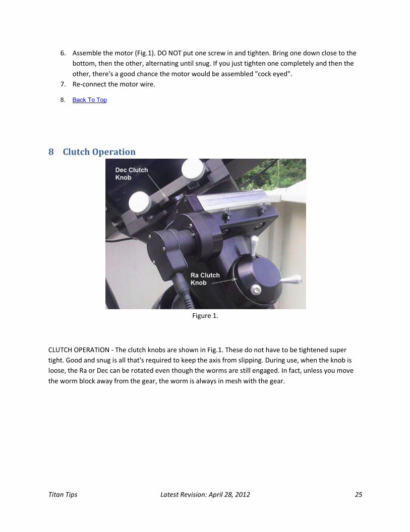
8 Clutch Operation
Figure 1.
CLUTCH OPERATION - The clutch knobs are shown in Fig.1. These do not have to be tightened super
tight. Good and snug is all that's required to keep the axis from slipping. During use, when the knob is
loose, the Ra or Dec can be rotated even though the worms are still engaged. In fact, unless you move
the worm block away from the gear, the worm is always in mesh with the gear.

Titan Tips Latest Revision: April 28, 2012 26
Figure 2.
Figure 3.
The reason these axes can be rotated with the knob loose is that plastic piece sandwiched in between
the upper and lower assemblies. See Fig.2 & Fig.3. The lower assembly is the part that contains the
worm and gear. The upper assembly is the part that has the Ra or Dec stuff. With the clutch knob loose,
the upper assembly can slip on the plastic piece. The plastic piece acts as a bearing. If it weren't there,
you would have aluminum rubbing against aluminum, and that would be bad. The surfaces would
eventually gall. When you snug the clutch knob, you are clamping the upper assembly to the lower
assembly and when the worm turns the gear the whole assembly rotates.
Let's look at the Ra axis. With the clutch knob loose, the weight of the entire Dec assembly including the
telescope assembly, and counterbalance weights imposes a huge load through that plastic bearing. So
with the knob loose, and you rotate the assembly, friction at the plastic bearing caused by things like
coefficient of friction of the materials, surface finish of the rubbing components, etc., create some drag
or resistance to rotation. This is why some people do their balancing with the worm disengaged. With it
disengaged, the assembly can rotate on the internal steel bearings which are very free-wheeling.
See Clutch Modification.
Back To Top

Titan Tips Latest Revision: April 28, 2012 27
9 Re-Greasing the Titan DEC Assembly by Robert Anderson (tips and
edited by Scott Oates) The fall, winter and early spring nightly temperatures here in Canada can average between -10F to +5F
and the grease that comes in the Titan mount seems to thicken too much for these temperatures and
therefore contribute to Stalls when tracking. The RA assembly has to date, not been effected by the low
temperatures.
Proper tools and agents are required for this procedure. To clean the old grease off the components, 3M
Citrus Base Cleaner was used though any good de-greaser can be used. There is only one nylon gear and
the rest are all metal.
Following the cleaning off of the old grease, the parts were washed in 99% Isopropyl Alcohol and re-
greased with Dow Corning 33 Extreme Low Temp Bearing Grease, (Light consistency). In-addition, you
will need a pair of Snap Ring Pliers, a full set of Allen Keys, a strap wrench, a Scott Knob, a box of cotton
swabs, rags and your ready to go.
The total process took about 4 hours (not including the additional two hours trying to get the main shaft
off). I was not successful in getting that shaft off even with a heat gun, Liquid Wrench and a substantial
amount of effort with the strap wrench. Scott did have success getting his off so I think it's really
dependant on when the shaft was installed and how hard it is to get off. I worked around that problem
by working the cleaners and re-greasing with the shaft in place.
Each picture can be clicked to go to a full page shot of that particular component. Just remember that
the full page shot is about 500K each.
Good luck and have fun.
Bob Anderson
Start by taking the Worm gear off of the DEC housing and motor from Worm assembly

Titan Tips Latest Revision: April 28, 2012 28
Three sizes of Allen Keys are required to take the motor off and disassemble gear housing from the worm block.
It is our suggestion that there is no need to take the plastic cover off the gear housing. The motor is
supported by the plastic cover and needs all three contact points to maintain proper alignment with the
internal gears.
I have taken mine apart so that you can see the internal workings but there is no need to
disassemble this part. The grease that is used in here is different from the the worm/gear grease
you want to replace.
I unfortunately broke one of the guide pins of the plastic housing as can be seen on the picture of
the metal plate on the far right.
You can use a pair of pliers to unscrew the two posts. This will allow you to slip the complete gear
reduction assembly out of the aluminum block. If you do take this assembly apart, the translucent
gear on top will slid off so store carefully.
On the left is Scott Oates famous Knob. Very handy for custom tuning the pressure of the worm bearings on both the DEC and RA worm blocks. On the right, you can see the worm gear snuggled in its bearing. Upon loosening the gear on the other side, the complete worm will come out this end.

Titan Tips Latest Revision: April 28, 2012 29
Double check the location of the gear on the end of the worm shaft. You can see in this shot on the left that it is even with the end of the shaft. On the inside of the gear, is the allen key screw to loosen off the gear from the worm shaft. On the right, you can see the disassembled worm assembly. Do not take off the gear side bearing. That bearing has been installed at a specific distance into the block and is next to impossible to extract. There are no parts in there that need attention.
While preparing for the disassembly, I noticed that the DEC Gear cover was missing a screw. Turns out that it is not required for any structural support. There is a single screw that holds the center shaft on to the saddle. In this picture, I have already taken the four bolts off the plate at each corner.

Titan Tips Latest Revision: April 28, 2012 30
On the left, you will see the saddle plate with center shaft. This shaft rides on two bearings in the main shaft. I cleaned the grease off twice. The first time as I disassembled and then I re-greased it with the original grease in the shaft so that I could take it outside in 5F temperatures to see how it reacted. It certainly is not designed for the temperatures of the Great White North
Again, on the left is a shot of the pressure wheel and the locking ring that holds it onto the center shaft. On the right is the ring off. At this point, simply unscrew the pressure wheel up off the center shaft.
Underneath the pressure wheel are two wavy washers. These maintain the right separation of the pressure wheel form the bearing below them. Slide these rings off the center shaft and slide the base locking assembly up. The bearing stays with this bottom piece. In-between these two plates is the plastic clutch pad. When re-assembly, make absolutely sure there is

Titan Tips Latest Revision: April 28, 2012 31
no grease on it or the two matching metal surfaces. You can also see the first of two sets of bearings in side the main shaft. They and the bearings below the gear are what you want to re-grease.
On the right is the cover plate that has four allen key bolts that affix it securely to the gear below through the gear housing.
With the four bolts off above, and the two allen key bolts off of the gear cover, below it, you will see a collar with three setting screws and four outside screws. Undo the four outside screws and slide the collar off of the shaft. It hold the gear down in place riding on the bearings you can see that are pressure fitted to the gear assembly on the right.
Now slide the gear up and off the central shaft. Under the gear, you will see a three plate assembly that includes two race and the Thrust bearings. I cleaned all of the grease off the thrust bearings and after a cleaning with alcohol, air can drying, I re-greased with the Dow 33 grease. Be careful with the three bearing areas that you will be cleaning and bearings and the two sets of bearings in the main shaft.

Titan Tips Latest Revision: April 28, 2012 32
DO NOT USE COTTON SWABS ON THESE BEARINGS.
Use your fingers to wash the bearings with the de-greaser and the alcohol cleaner. Re-apply the new grease with your fingers again. Getting cotton bits ont he bearings will cause all sorts of problems.
With the bearings removed, unscrew the remaining three bolts and take cover plate and bottom Gear housing off. This will give you a clear view of where the shaft screws into the housing and also gives you maximum area to try and get the shaft out. I tried to take the Main shaft off with all sorts of techniques. I heated the main block with a heating gun at 850 degrees till the block was hot to touch while cooling the shaft with a towel full of ice. I soaked the threaded part with Liquid Wrench and used a strap wrench on it but to no avail.
Scott and I agree that taking the shaft off is probably not needed nor desired. Do not use a pipe wrench to try and get it off, you will just damage the main shaft.
There are two key bearings inside the Main Shaft that need re-greasing. I eventually
Titan Tips Latest Revision: April 28, 2012 33
spayed the 3M de-greaser down the tube at the bearings and rolled the bearings back and forth by finger. I then washed the bearings with alcohol and blew dry with canned air. I liberally re-applied the Dow 33 grease by finger working it into the bearings as much as possible.
Back To Top
I took the RA shaft bearing area apart so that I could get to the bottom bearings on the Main Shaft. It is a
very tight fit. There are four bolts inside this assembly but I was un-able to find out their purpose. Taking
out did not assist in taking the shaft out.
I also un-screwed the bottom part of the housing that you screw the weights bar into and used a long
piece of plastic to apply grease to the bottom gear.
REASSEMBLE by simple reversing the procedure.
Good luck.
Back To Top
10 Worm Lubrication There are many good lubes that can be used on the gears. Cleanliness prior to lubricating is very
important. Dirt or foreign particles can lead to premature gear wear and problems in guiding. Don't let it
get there in the first place. Several lubes have been mentioned on the user groups including SLICK 50
grease. So that is what I used when I had my worm box off. You do not need to completely hide the gear
teeth with the lube. Don't do it. That's way too much. Just a small amount all the way around. Apply it
with a popsicle stick or toothpick or plastic pointer. Metal objects against the teeth may cause damage.
I'm unsure of the frequency required but my guess is that once a year should suffice. If you operate in a
hot climate, the melting temperature of the lube would be very important. In a cold environment, the
lube should retain its viscosity characteristics. So in selecting a lube, and the lubricating intervals, the
viscosity vs. temperature range should be considered when deciding what lube you should use.

Titan Tips Latest Revision: April 28, 2012 34
Figure 1.
Fig.1 is an image of the gearbox to worm adapter that I had taken for this tip section. The entire gear
assembly had already been very lightly greased with Slick50. What is shown on the surface is Slick50
grease that has melted?. What looks like a scratch in the bore is really just grease. I am VERY
disappointed to see the residue. This to me looks like the Slick50 has melted. My typical ambient
temperature for this time of year is about 80-85 F. But I'll leave it for now and monitor it with time.
The Meade LX200's have a very dark looking grease. As though tinted with molybdenum disulfide. It
stayed in place forever.
Well, I couldn't leave it for now. I did some searching on the Meade Mapug group and came up with
some interesting grease. The advertised temperature range is fantastic and it comes in a neat plastic
syringe. Not knowing how much 12ml is, I ordered and received 3 syringes. I planned on re-greasing my
worms the next day and I was anxious to know if the stuff would perform in temperature as advertised.
So I put a small dab on a piece of aluminum foil and into the toaster oven at 250F and let it stay there for
about 30 minutes. The rest of the syringe was put into a baggie and in the freezer until the next
morning. THIS STUFF IS GREAT. When I removed the dab from the oven, absolutely no sign of melting. In
the morning, I retreived the rest from the freezer and applied a dab to a paper. It came out as it did
before going into the freezer. So I cleaned my worms, (got rid of the Slick50 kids stuff), and greased
them with the Hi-Slip stuff. I like this grease a lot and I'm glad I purchased 3 of them. One syringe is
more than enough to grease both worm and gear assemblies.
Mfr: SENTRY SOLUTIONS - Lubricates High Friction Areas; Protects Steel In Extreme Temperatures

Titan Tips Latest Revision: April 28, 2012 35
Molybdenum-disulfide, in a corrosion-resistant, synthetic grease prevents galling in high-load areas.
Won’t run in extreme heat up to +650°F; won’t gum up in cold down to -65°F. Packaged in a syringe that
makes it easy to apply precisely. Water resistant and long lasting so it won’t wash away.
SPECS: .41 fl. oz. (12 ml) syringe. $6.95 Click here for Hi Slip Grease
Joe Mize has used Dow # 33 (see below) DOW Corning Synthetic Grease, No. 33 Extreme Low-Temperature Grease, -100° to +355° F, (Light consistency).
McMaster-Carr part number "1252K12", 5.3oz $14.20US. Click here for Dow #33
Back To Top

Titan Tips Latest Revision: April 28, 2012 36
11 Wire Management
WIRE MANAGEMENT - I knew I had to do something about all those wires. You can't see them in the
above image but from the SCT alone come SIX wires. Now think of it. How can you have six wires tangled
or not, and not expect one of them to get caught on something. You can't! Plus it just looks very messy
& uncontrolled.
That heavy looking wire is actually wire loom, sort of a grooved looking tube that is split along it's entire
length. It is very lightweight and effective. I purchased it at a local automotive store and it's inexpensive.
In that harness are the 3 wires you see, camera power, USB, & guider. Also in the same tube is the dew
(preventer) wire, which I made longer, the Robofocus wire, and the Optec TCF-s wire. Six managed
wires. I can slew the SCT anywhere and the harnessed set goes for the ride without imposing any
deterrents. One end of the split tube is attached to the SCT grab handle with a Velcro tape thing that I
purchased at the auto store. It looks like a roll of tape. One side is fine hook and the other side is fine

Titan Tips Latest Revision: April 28, 2012 37
pile. It is very good stuff. The other end of this harness terminates at the SBIG camera power supply (the
black box near the top of the pier). Things just seemed to work well for me this way. Under that box are
2 power strips that plug into the main ground fault protected circuit located just underneath which goes
underground to the house. From the power strips come the wires for all things electrical requiring 110V.
This includes the Pyramid 20 amp 13.8V power supply. Gemini and the heater get their juice here.
CAUTION: Some people have experienced interference from adjacent wires, especially the CCD USB
cable. Dew Heaters are notorious for introducing interference.
Not shown is my laptop computer which is operated from inside the house via Remote Desktop. So that
means going to the laptop is a CAT5 cable for the remote operation, plus the power cord, plus a USB
cable coming from that white box which is a 4 port USB hub. These wires are also in one of those split
tube harnesses. It is amazing the difference wire management has made for me.
Another method is enjoyed by Joe Mize: Radio Shack has Nylon Wire Twists, these are 3/8"-1/2" loops
with beads on the ends. Slip the wires inside the loop and twist the beads together one half turn to
bundle wires.
Back To Top
12 Power Supply & More Horsepower Where does the Titan get its juice from?
The following has been copied from the Gemini manual:
12.1 2.1.4 Power Requirements The Gemini System requires 12–18 Volts DC, 3 Amps to operate. You will need to have a battery or
regulated DC power supply. Your choice of power supply is very important! Many DC power units are
not regulated, provide too little current, and too little or too much voltage. This can cause problems
with the Gemini. If you plan to run other equipment from the power supply, make sure it has enough
additional capacity. Choose your power supply carefully, and avoid potential problems such as long
power cables.
The Losmandy DC power supply (available separately) meets all the above requirements.
From one of the forums, I have read that the above power supply is similar to the Radio Shack product. I
had one and thought it was wimpy. When my Titan was on order, I learned that a really good power
supply was available from Pyramid Power Supply. A good supplier of Pyramid Power Supplies is
Electronics.com. They have a good selection of models and fair prices. Many models meet our needs
with and without the cigarette plug connector. I purchased one rated at 20 amps so as to have plenty of
additional capacity for my "dew preventor" and anything else I may need to add. I like plenty of passing
power. I checked the output voltage with a digital multimeter and verified that it was indeed 13.8 volts.
Having also read that the Titan servo motors need 12-18 volts, but that they perform better at 18 volts, I
purchased the Lacey converter which ups the ante from 13.8 volts to 18 volts. I connected it to the

Titan Tips Latest Revision: April 28, 2012 38
Pyramid and verified that it was indeed 18 volts. This is supposed to help with the motors that do need
help. Not being an electrician, I just did what the experience and wisdom of others suggested. No
regrets.
It has been suggested to change GOTO and SLEW speeds from the default number of 1200 to 900. This
helps reduce stress on the motors. Since I have a fairly heavy 12" Meade OTA, accessories, and 63 lbs of
counterweight, I lowered mine to 500 and the motors stay cool.
Back To Top
13 Miscellaneous Tips Since I hardly ever have my diagonal with an eyepiece, but instead have my CCD camera attached, I
would build a pointing model by centering a star in the finderscope, then take several images moving
the mount in between, and eyeball putting the star in the center of the image. For more precision, if you
use CCDSoft or MaximDL, you can have crosshairs on the image so that for each additional align, the star
can be accurately placed. In CCDSoft, when the image appears, press the number "6" key. In MaximDL,
right click on the image and select "Crosshairs" from the drop down menu. See Fig.1. If you don't use
either of these programs, search the help file of the program you do use. I just discovered this for
CCDSoft from the SBIG user group. I immediately checked MaximDL as well and found it. Of course all of
the above may apply when the lousy clouds and rain in CT go away!
CCDSoft Crosshairs
MaximDL Crosshairs
The Gemini default setting for GOTO and slew speeds for the Titan are 1200. This appears to be way too
high (fast). Reduce them down to at least 900. I have put mine at 600. The weight of my OTA is about 43
lbs, plus dovetail, camera, 63 lbs counterweight, etc. This is quite a bit of weight for the motors to
accelerate. Reducing the speed will help keep those motors cool.
MOTOR HEATING UP - likely causes:

Titan Tips Latest Revision: April 28, 2012 39
Slew and GOTO speeds too high. Default for the Titan is 1200 and is way too high. Lower it to
900 or lower.
System is unbalanced by a substantial amount. See Balancing your GEM
Worm to gear engagement is too tight. Not enough clearance. See Worm Clearance &
Adjustment
When checking for motor temperature, place your fingers on the reduced diameter shown in
Fig.4 . The motor should NEVER feel hot, just very slightly warm.
Figure 4.
Back To Top

Titan Tips Latest Revision: April 28, 2012 40
14 MY OBSERVATORY - Bob Allevo
It measures only 6'x6' and it is small! I originally had my mini-MAX observatory which included a
permanent pier and a wedge mounted Meade 12" f/10 LX200 UHTC. I also have a Meade 10" f/6.3
GPS UHTC and a Takahashi Sky90 that would ride piggyback. That observatory had to go with the coming of the Titan mount. I wanted to improve my guiding for astrophotography, which is my main purpose for owning telescopes.
The floor is all 4x4 and 3/4 thk pressure treated plywood. The walls are "T11", and the roof is made from
10mm thk Aluminite which is a composite of a rubber/plastic core faced on both sides with .019 thk
aluminum and painted white. It is very impervious to any kind of weather and is lighter than plywood
yet very strong. NO warping here. The cost is about $160 per 4'x8' sheet. The roof opens with polished
stainless hinges. All hardware is also stainless. So opening these roof panels required considerations for
snow and lifting to open. Hence 6'x6' size. Since the pier already existed, I had to design the observatory
so that my largest SCT, mounted on the Titan, would not be restricted in movement. I did the design in a
CAD program and scaled the Losmandy Titan picture so I could put it in my 3D CAD dwg. I sent a picture
of a Titan mount with a SCT attached to a Titan owner (actually HIS web site picture modified) with a
request for a couple of key dimensions. He answered my email with the dimensions. Thank you Alan
Chen.

Titan Tips Latest Revision: April 28, 2012 41
The door is on the opposite side shown and is also made from Aluminite.
Now I know it's tiny and would not be the best for visual observing, but for my imaging needs, it works. I
do all of my imaging remotely from inside the house. I am free from bugs, heat, humidity, black bears,
and from the cold.
This is an overall view of my setup.

Titan Tips Latest Revision: April 28, 2012 42
A closer view.
The corner in which I set things up for imaging prior to going into the house.

Titan Tips Latest Revision: April 28, 2012 43
This view shows the RoboFocus motor (blue) which is used to move the main mirror to a pre-set location
determined by the particular focal length setup. Also seen is the Optec TCF-s focuser, located between
the camera/filter wheel and scope, which is used for fine focus. The camera is an SBIG ST-10XME with
CFW8A filter wheel. The SBIG adaptive optics module is not shown in this setup.

Titan Tips Latest Revision: April 28, 2012 44
This is a view of my Takahashi Sky90 refractor. It is a 90mm f/4.5 system used for wide field
astrophotography.
Back To Top
15 Titan Tracking Example These images were taken after drift alignment done about two months ago. No drift after five minutes.
A decent PEC was finally done just prior to these images.
Figure 2.
Fig. 2 pushes the envelope by going 10 minutes unguided at 2815 mm

Titan Tips Latest Revision: April 28, 2012 45
Figure 2.
The drift seen in Fig. 2 is in Dec. (Camera mounted at angle)
Back To Top
16 Some Knowledgeable, Helpful, Titanites • Alan Chen
• Joe Mize
• Scott Oates

Titan Tips Latest Revision: April 28, 2012 46
17 Appendix A - Drift Alignment Notes Last year (September 2008) when I got my Titan and first started using it I went through a learning
curve: from fork-mount to GEM, and the peculiarities of the Titan mount itself. Once I was comfortable
with the mechanical aspects of the mount I began drift aligning using an SBIG ST2000XM CCD and
MaximDL to watch drift for each axis, and then make adjustments. I would see, at times, the stars
continue to drift in RA (east/west) for up to 30 seconds (in time) or more after slewing. To make a long
story short, I came to the conclusion that something was wrong with the Gemini system and sent the
unit back to Losmandy for "repair." I now know that conclusion was wrong.
Recently I began drift aligning the mount because I had got it out of whack from some adjustment last
spring. After much tedium, I obtained a very accurate, polar-aligned mount.
Still, I would notice drift of stars (elongated streaks) as the mount seemed to "settle" after a slew - this
was always, as before, in the RA axis east/west. Finally I realized what this was. It was the settling of the
counterweight shaft after a slew to the east. Because there is some play in the RA worm (if I tighten it
too much I get motor lag errors), when I would slew to the east it would eat up the backlash. When the
slew stopped, gravity would take over, and slowly the counterweight shaft would settle as I'd watch the
stars in the CCD image showing up as streaks until it was all settled. Also, my mount was very balanced
- in fact, it was too balanced...
After many tests/tweaks I've confirmed without a doubt what that settling drift was (that it was not
polar misalignment as I had originally thought last year and for a long while). Recently, I've been
tweaking the bias on the eastward side and testing the drift, and making very small adjustments to the
worm tightness. Although there was a slight bias, it was only very slight. So I made a couple of
adjustments in the counterweights and added an 8-ounce "bias weight" that effects a firm but gentle
bias on the CW shaft. If I gently rock the shaft upward, it settles back toward the east. Of course, if the
scope is on the east side (CW shaft on west), the bias would then be on the west side.
For any new Titan (or GEM for that matter) owners, it is imperative that you understand this. If there is
play in the RA axis and it is not properly biased to the east you will see in the CCD the aforementioned
elongated star streaks until it settles - if you know this, then you won't mistake it for some other kind of
drift (i.e. polar drift) or Gemini acting weird.
My point: the tracking is very good, steady - very low PE. Tonight there was a fair amount of wind, with
15-20 mph gusts, and yet I was taking 10min subs (guided) with no distortion in the images. So, I guess
the above is a long-winded way of saying make sure you have a slight but definite bias to
the east. Hope this was helpful to others who may have experienced this sort of thing.
Taking the above into consideration, I would now refer to Bob Allevo's section on Balancing. In
particular, his method for balancing on both the east and west side. If you think about it, if you bias the
scope on the east side, that's fine. But what if you do a meridian flip? That same amount of bias would
apply to the west side (CCW Shaft) but in the opposite direction (i.e., it will pull the mount west).

Titan Tips Latest Revision: April 28, 2012 47
What's not good about that is if there is some play in the RA worm (and there should be), than the
precision of your alignment can be thrown off since it is based on an eastward bias - not westward. Bob
suggests a method for taking care of this, but it would require manually removing the "bias weight" after
a meridian flip (so if you're in your house, you've got to trudge out to the observatory and do that).
I would love to find a way to automatically maintain the bias on the eastward side after a meridian flip -
perhaps with some kind of tension spring and a pulley... instead of a 4 or 8oz. weight.
Back To Top
18 Appendix B: Titan 50 Gear Pics
Figure 1. Maxon Motor from a Titan 50

Titan Tips Latest Revision: April 28, 2012 48
Figure 2. Spur Gear from a Titan 50

Titan Tips Latest Revision: April 28, 2012 49
Figure 3. Worm Gear from a Titan 50

Titan Tips Latest Revision: April 28, 2012 50
Figure4. Wormwheel from a Titan 50
Back To Top