Welcome to the world of solutions - Sunnforest Enterprises · Ordering Information 1.1 Engine...
38
Stationary/Industrial Exhaust Catalog 2005 Welcome to the world of solutions
Transcript of Welcome to the world of solutions - Sunnforest Enterprises · Ordering Information 1.1 Engine...

Stationary/IndustrialExhaust Catalog
2005
Welcome to the worldof solutions
Ordering Information 1.1
Engine Exhaust Silencers 2.1
Emissions Solutions 3.1
Technical Capabilities 4.1
Rota
ry P
ositi
ve
Blow
er S
ilenc
ers
1.1
23
See
page
1.1
for o
rder
ing
info
rmat
ion
| w
ww
.uni
vers
alsi
lenc
er.c
om1
4Ta
ble
of C
onte
nts
Table of Contents2005 Full-Line Catalog
NoteAll dimensions in inches and weights in pounds, unless otherwise indicated. Revision 2.1 1/05

Rota
ry P
ositi
ve
Blow
er S
ilenc
ers
1.1
Orde
ring
Info
rmat
ion
1.1
OrderingInformation
14
3Se
e pa
ge 1
.1 f
or o
rder
ing
info
rmat
ion
| w
ww
.uni
vers
alsi
lenc
er.c
om2
New York, Pennsylvania,Delaware, New JerseyHester, Greer Associates, Inc.152 Kensington RoadGarden City, NY 11530Tim HesterTelephone: 516-746-2484
Maine, Vermont, New Hampshire,Massachusetts, Rhode Island,ConnecticutGoodall Industrial Equipment Co.2 Summer Street, Suite 29Natick, MA 01760Peter GoodallTelephone: 508-651-2668
West Virginia, Virginia, MarylandBruster & Associates2300 Corner Rock RoadMidlothian, VA 23113Dave BrusterTelephone: 804-794-4136
Georgia, South Carolina, North CarolinaLawing & Associates4543 Charlotte Hwy., Suite 14Lake Wylie, SC 29710Alex LawingTelephone: 803-831-1205
FloridaWorld Marine Marketing4707 140th Avenue North, Suite 315Clearwater, FL 33762Tom ManningTelephone: 727-530-7709
OhioAnderson-Bold, Inc.24050 Commerce Park RoadCleveland, OH 44122Guy MercerTelephone: 216-360-9800
North Dakota, South Dakota,Minnesota, Iowa, Wisconsin,Michigan, IndianaMidwest Power Systems1921 North Hampton CourtPeoria, IL 61604Jeff DanielsTelephone: 309-679-2740
Lousiana, Arkansas, Mississippi,Alabama, Tennessee, KentuckyUnderwood Sales2783 Longate DriveMemphis, TN 38132Dean Underwood, Jr.Telephone: 901-332-4701
Texas, Oklahoma, Kansas,Nebraska, Missouri, IllinoisDecco, Inc.5215 East 71st Street, Suite 1600Tulsa, OK 74136Don MillerTelephone: 918-481-8722
Montana, Idaho, Wyoming,Nevada, Utah, Colorado, Arizona,New MexicoE.L. Pack & Associates3635 West Saddleback RoadPark City, UT 84060Ed PackTelephone: 435-649-3837
Have special silencing needs? Contact one of our nationwide representatives.
Alaska, Washington, Oregon,CaliforniaOtto Miller6021 104th Avenue N.E.Kirkland, WA 98033Otto MillerTelephone: 425-822-6603
HawaiiWest Pacific Power Products560 North Nimitz Hwy.Honolulu, HI 96817Clay AndersonTelephone: 808-522-0522
Puerto RicoGen Set SpecialtiesP.O. Box 51476Levittown, PR 00950Roberto BuendiaTelephone: 787-795-2413Fax: 787-795-9768
Looking for pricing?
Ask your local representativeto send you the 2005
Nelson Silencer price list.
Rota
ry P
ositi
ve
Blow
er S
ilenc
ers
2.1
Engi
ne E
xhau
stSi
lenc
ers
24
3
2.1
See
page
1.1
for
ord
erin
g in
form
atio
n |
ww
w.u
nive
rsal
sile
ncer
.com
1
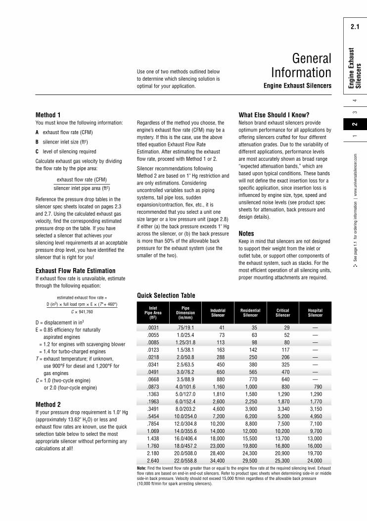
Method 1You must know the following information:
A exhaust flow rate (CFM)
B silencer inlet size (ft2)
C level of silencing required
Calculate exhaust gas velocity by dividingthe flow rate by the pipe area:
Reference the pressure drop tables in thesilencer spec sheets located on pages 2.3and 2.7. Using the calculated exhaust gasvelocity, find the corresponding estimatedpressure drop on the table. If you haveselected a silencer that achieves yoursilencing level requirements at an acceptablepressure drop level, you have identified thesilencer that is right for you!
What Else Should I Know?Nelson brand exhaust silencers provideoptimum performance for all applications byoffering silencers crafted for four differentattenuation grades. Due to the variability ofdifferent applications, performance levelsare most accurately shown as broad range“expected attenuation bands,” which arebased upon typical conditions. These bandswill not define the exact insertion loss for aspecific application, since insertion loss isinfluenced by engine size, type, speed andunsilenced noise levels (see product specsheets for attenuation, back pressure anddesign details).
NotesKeep in mind that silencers are not designedto support their weight from the inlet oroutlet tube, or support other components ofthe exhaust system, such as stacks. For themost efficient operation of all silencing units,proper mounting attachments are required.
GeneralInformation
Engine Exhaust Silencers
exhaust flow rate (CFM)
silencer inlet pipe area (ft2)
Exhaust Flow Rate EstimationIf exhaust flow rate is unavailable, estimatethrough the following equation:
D = displacement in in3
E = 0.85 efficiency for naturally aspirated engines
= 1.2 for engines with scavenging blower= 1.4 for turbo-charged engines
T = exhaust temperature; if unknown, use 900°F for diesel and 1,200°F for gas engines
C = 1.0 (two-cycle engine) or 2.0 (four-cycle engine)
estimated exhaust flow rate =
D (in3) � full load rpm � E � (T°� 460°)
C � 941,760
.0031
Inlet Pipe Area
(ft2)
.0055
.0085
.0123
.0218
.0341
.0491
.0668
.0873
.1363
.1963
.3491
.5454
.78541.0691.4381.7602.1802.640
.75/19.11.0/25.41.25/31.81.5/38.12.0/50.82.5/63.53.0/76.23.5/88.94.0/101.65.0/127.06.0/152.48.0/203.210.0/254.012.0/304.814.0/355.616.0/406.418.0/457.220.0/508.022.0/558.8
4173
113163288450650880
1,1601,8102,6004,6007,200
10,20014,00018,00023,00028,40034,400
356398
142250380565770
1,0001,5802,2503,9006,2008,800
12,00015,50019,80024,30029,500
295280
117206325470640830
1,2901,8703,3405,2007,500
10,20013,70016,80020,90025,300
————————790
1,2901,7703,1504,9507,1009,700
13,00016,00019,70024,000
Pipe Dimension
(in/mm)
IndustrialSilencer
ResidentialSilencer
CriticalSilencer
HospitalSilencer
Quick Selection Table
Note: Find the lowest flow rate greater than or equal to the engine flow rate at the required silencing level. Exhaustflow rates are based on end-in end-out silencers. Refer to product spec sheets when determining side-in or middleside-in back pressure. Velocity should not exceed 15,000 ft/min regardless of the allowable back pressure(10,000 ft/min for spark arresting silencers).
Method 2If your pressure drop requirement is 1.0" Hg(approximately 13.62" H2O) or less andexhaust flow rates are known, use the quickselection table below to select the mostappropriate silencer without performing anycalculations at all!
Use one of two methods outlined belowto determine which silencing solution isoptimal for your application.
Regardless of the method you choose, theengine’s exhaust flow rate (CFM) may be amystery. If this is the case, use the abovetitled equation Exhaust Flow RateEstimation. After estimating the exhaustflow rate, proceed with Method 1 or 2.
Silencer recommendations followingMethod 2 are based on 1" Hg restriction andare only estimations. Consideringuncontrolled variables such as pipingsystems, tail pipe loss, suddenexpansion/contraction, flex, etc., it isrecommended that you select a unit onesize larger or a low pressure unit (page 2.8)if either (a) the back pressure exceeds 1" Hgacross the silencer, or (b) the back pressureis more than 50% of the allowable backpressure for the exhaust system (use thesmaller of the two).
Rota
ry P
ositi
ve
Blow
er S
ilenc
ers
2.2
Engi
ne E
xhau
stSi
lenc
ers
43
2.2
See
page
1.1
for
ord
erin
g in
form
atio
n |
ww
w.u
nive
rsal
sile
ncer
.com
21
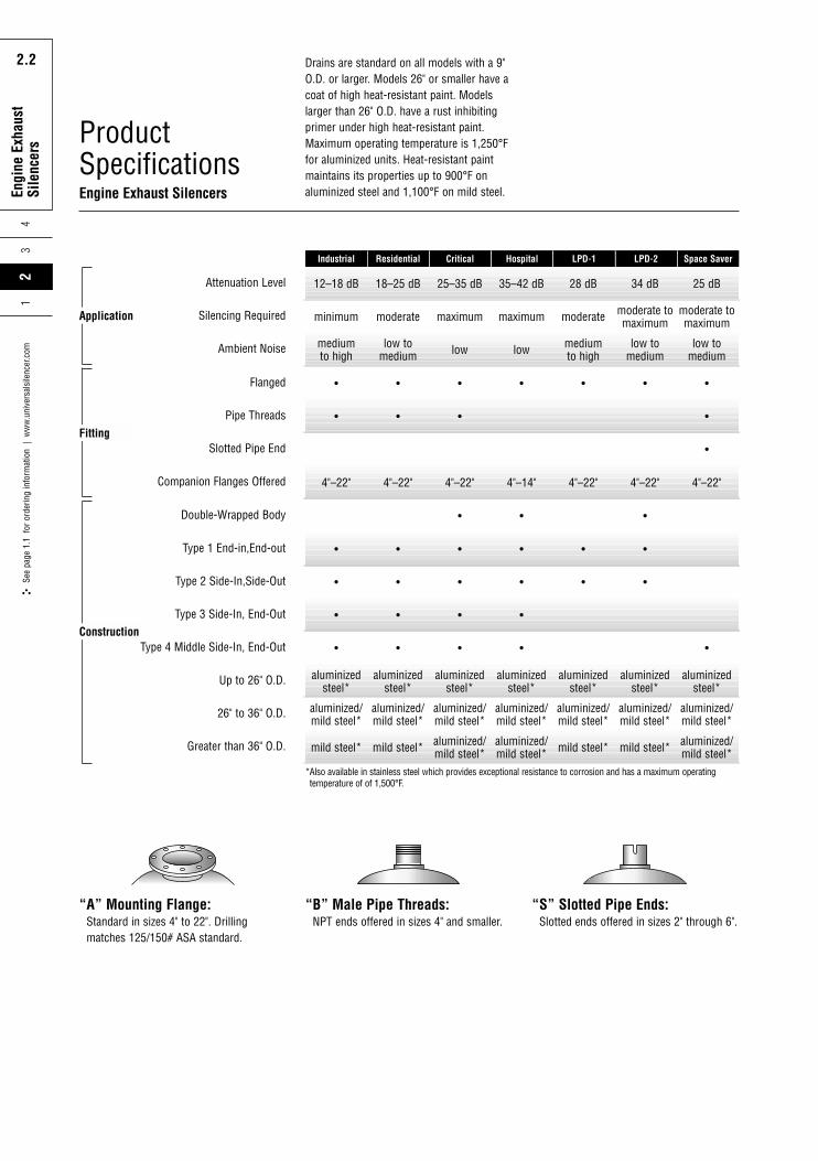
ProductSpecificationsEngine Exhaust Silencers
12–18 dB 18–25 dB 25–35 dB 35–42 dB 28 dB 34 dB 25 dB
minimum moderate maximum maximum moderate moderate tomaximum
moderate tomaximum
medium to high
4"–22" 4"–22" 4"–22" 4"–14" 4"–22" 4"–22" 4"–22"
• • • • • •
• • • • • •
• • • •
• • •
aluminizedsteel*
aluminized/mild steel*
mild steel*
aluminizedsteel*
aluminized/mild steel*
mild steel*
aluminizedsteel*
aluminized/mild steel*
aluminized/mild steel*
aluminizedsteel*
aluminized/mild steel*
aluminized/mild steel*
aluminizedsteel*
aluminized/mild steel*
mild steel*
aluminizedsteel*
aluminized/mild steel*
mild steel*
aluminizedsteel*
aluminized/mild steel*
aluminized/mild steel*
low tomedium low low medium
to highlow to
mediumlow to
medium
Residential Critical Hospital LPD-1 LPD-2 Space Saver
Attenuation Level
Silencing Required
Ambient Noise
Type 1 End-in,End-out
•Slotted Pipe End
• • • •Pipe Threads
• • • • • • •Flanged
Type 2 Side-In,Side-Out
Type 3 Side-In, End-Out
• • • • •Type 4 Middle Side-In, End-Out
Double-Wrapped Body
Companion Flanges Offered
Up to 26" O.D.
26" to 36" O.D.
Greater than 36" O.D.
Industrial
Application
Fitting
Construction
“A” Mounting Flange:Standard in sizes 4" to 22". Drillingmatches 125/150# ASA standard.
“B” Male Pipe Threads:NPT ends offered in sizes 4" and smaller.
“S” Slotted Pipe Ends:Slotted ends offered in sizes 2" through 6".
Drains are standard on all models with a 9"O.D. or larger. Models 26" or smaller have acoat of high heat-resistant paint. Modelslarger than 26" O.D. have a rust inhibitingprimer under high heat-resistant paint.Maximum operating temperature is 1,250°Ffor aluminized units. Heat-resistant paintmaintains its properties up to 900°F onaluminized steel and 1,100°F on mild steel.
*Also available in stainless steel which provides exceptional resistance to corrosion and has a maximum operatingtemperature of of 1,500°F.
Rota
ry P
ositi
ve
Blow
er S
ilenc
ers
2.3
Engi
ne E
xhau
stSi
lenc
ers
24
3
2.3
See
page
1.1
for
ord
erin
g in
form
atio
n |
ww
w.u
nive
rsal
sile
ncer
.com
1
40
31.5 63 125 250 500
51015
0
20253035
Octave Band Center Frequency, Hz
Insertion Loss, dB
Typical Attenuation Curves,Standard and Puck-Style Units
1K 2K 4K 8K
24
0 1 2 3 4 5 6 7 8 9 10 11 12 13 14
4
0
8
12
16
20
Exhaust Gas Velocity in Thousands (ft./min.)
Estimated Pressure Drop
(Inches of Water)
Pressure Drop, Standard Units
40
31.5 63 125 250 500
51015
0
20253035
Octave Band Center Frequency, Hz
Insertion Loss, dB
1K 2K 4K 8K
24
0 1 2 3 4 5 6 7 8 9 10 11 12 13 14
4
0
8
12
16
20
Exhaust Gas Velocity in Thousands (ft./min.)
Estimated Pressure Drop
(Inches of Water)
40
31.5 63 125 250 500
51015
0
20253035
Octave Band Center Frequency, Hz
Insertion Loss, dB
1K 2K 4K 8K
24
0 1 2 3 4 5 6 7 8 9 10 11 12 13 14
4
0
8
12
16
20
Exhaust Gas Velocity in Thousands (ft./min.)
Estimated Pressure Drop
(Inches of Water)
40
31.5 63 125 250 500
51015
0
20253035
Octave Band Center Frequency, Hz
Insertion Loss, dB
1K 2K 4K 8K
24
0 1 2 3 4 5 6 7 8 9 10 11 12 13 14
4
0
8
12
16
20
Exhaust Gas Velocity in Thousands (ft./min.)
Estimated Pressure Drop
(Inches of Water)
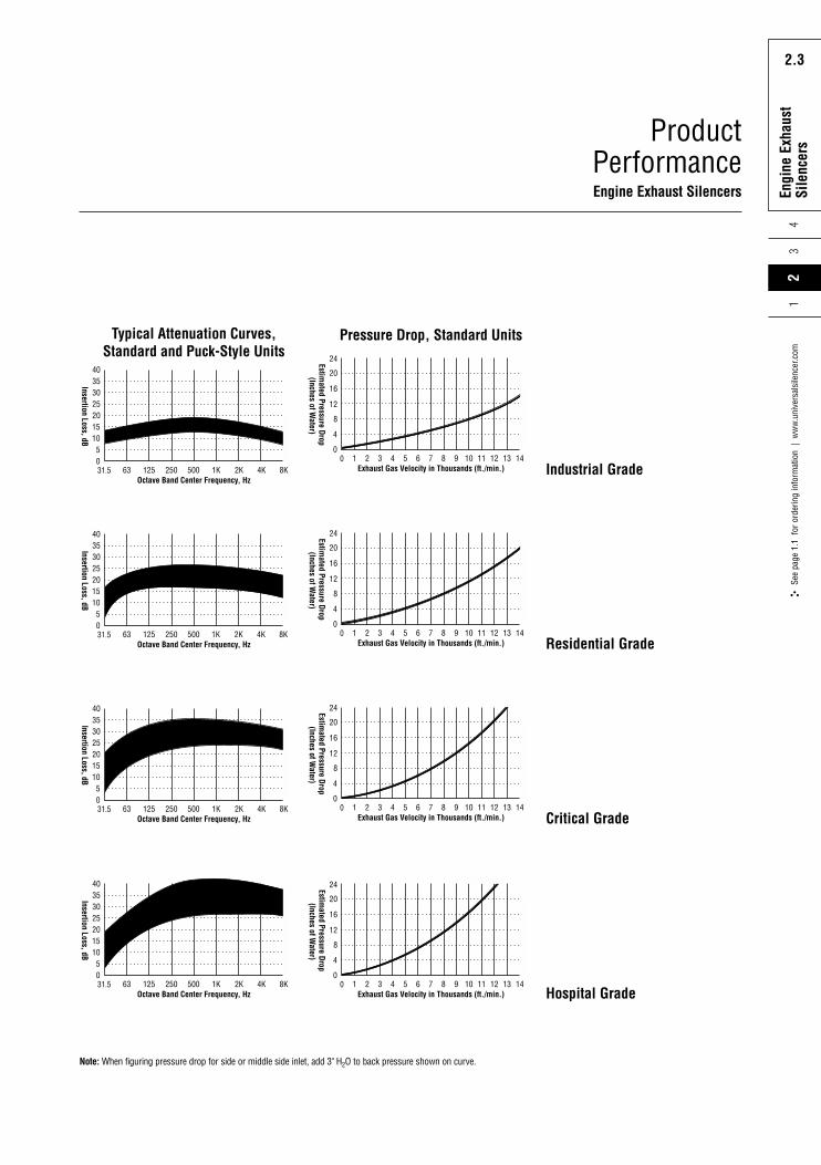
ProductPerformanceEngine Exhaust Silencers
Residential Grade
Critical Grade
Hospital Grade
Industrial Grade
Note: When figuring pressure drop for side or middle side inlet, add 3" H2O to back pressure shown on curve.
Rota
ry P
ositi
ve
Blow
er S
ilenc
ers
2.4
Engi
ne E
xhau
stSi
lenc
ers-
Puck
43
2.4
See
page
1.1
for
ord
erin
g in
form
atio
n |
ww
w.u
nive
rsal
sile
ncer
.com
21
Puck-StyleEngine Exhaust Silencers
L
Y
P
N
D
K
P
LY
P
D
C
J/2C/2
K
N
LY
P
D
C
J
J/2C/2
K
A
A
N
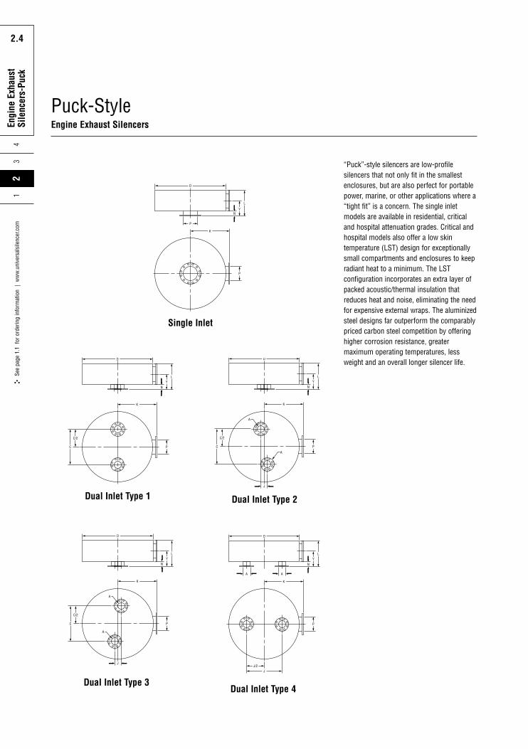
“Puck”-style silencers are low-profilesilencers that not only fit in the smallestenclosures, but are also perfect for portablepower, marine, or other applications where a“tight fit” is a concern. The single inletmodels are available in residential, criticaland hospital attenuation grades. Critical andhospital models also offer a low skintemperature (LST) design for exceptionallysmall compartments and enclosures to keepradiant heat to a minimum. The LSTconfiguration incorporates an extra layer ofpacked acoustic/thermal insulation thatreduces heat and noise, eliminating the needfor expensive external wraps. The aluminizedsteel designs far outperform the comparablypriced carbon steel competition by offeringhigher corrosion resistance, greatermaximum operating temperatures, lessweight and an overall longer silencer life.
Single Inlet
LY
P
D
C
J
J/2C/2
K
A
A
N
P
D
JJ/2
K
A A
LY
N
Dual Inlet Type 1
Dual Inlet Type 3Dual Inlet Type 4
Dual Inlet Type 2
Rota
ry P
ositi
ve
Blow
er S
ilenc
ers
2.5
Engi
ne E
xhau
stSi
lenc
ers-
Puck
24
3
2.5
See
page
1.1
for
ord
erin
g in
form
atio
n |
ww
w.u
nive
rsal
sile
ncer
.com
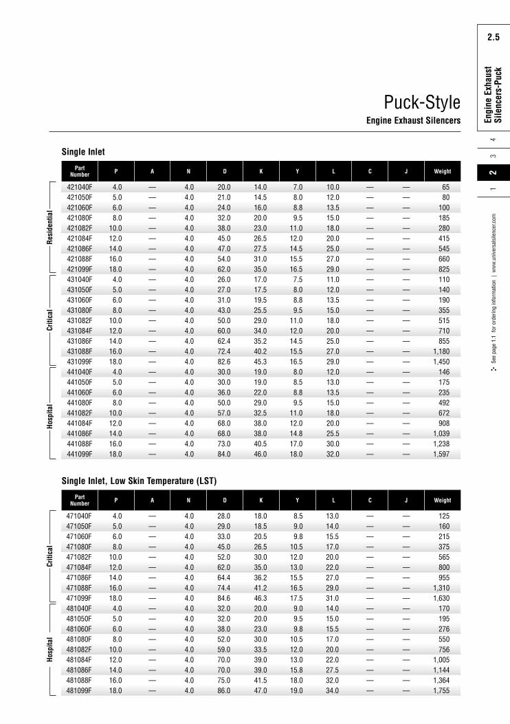
1Part
Number P A N D K Y L C J Weight
Criti
cal
Hosp
ital
471040F471050F471060F471080F471082F471084F471086F471088F471099F481040F481050F481060F481080F481082F481084F481086F481088F481099F
4.05.06.08.0
10.012.014.016.018.04.05.06.08.0
10.012.014.016.018.0
——————————————————
4.04.04.04.04.04.04.04.04.04.04.04.04.04.04.04.04.04.0
28.029.033.045.052.062.064.474.484.632.032.038.052.059.070.070.075.086.0
18.018.520.526.530.035.036.241.246.320.020.023.030.033.539.039.041.547.0
8.59.09.8
10.512.013.015.516.517.59.09.59.8
10.512.013.015.818.019.0
13.014.015.517.020.022.027.029.031.014.015.015.517.020.022.027.532.034.0
——————————————————
——————————————————
125160215375565800955
1,3101,630
170195276550756
1,0051,1441,3641,755
Single Inlet, Low Skin Temperature (LST)
Single Inlet
PartNumber P A N D K Y L C J Weight
Resi
dent
ial
Criti
cal
Hosp
ital
421040F421050F421060F421080F421082F421084F421086F421088F421099F431040F431050F431060F431080F431082F431084F431086F431088F431099F441040F441050F441060F441080F441082F441084F441086F441088F441099F
4.05.06.08.0
10.012.014.016.018.04.05.06.08.0
10.012.014.016.018.04.05.06.08.0
10.012.014.016.018.0
———————————————————————————
4.04.04.04.04.04.04.04.04.04.04.04.04.04.04.04.04.04.04.04.04.04.04.04.04.04.04.0
20.021.024.032.038.045.047.054.062.026.027.031.043.050.060.062.472.482.630.030.036.050.057.068.068.073.084.0
14.014.516.020.023.026.527.531.035.017.017.519.525.529.034.035.240.245.319.019.022.029.032.538.038.040.546.0
7.08.08.89.5
11.012.014.515.516.57.58.08.89.5
11.012.014.515.516.58.08.58.89.5
11.012.014.817.018.0
10.012.013.515.018.020.025.027.029.011.012.013.515.018.020.025.027.029.012.013.013.515.018.020.025.530.032.0
———————————————————————————
———————————————————————————
6580
100185280415545660825110140190355515710855
1,1801,450
146175235492672908
1,0391,2381,597
Puck-StyleEngine Exhaust Silencers
Rota
ry P
ositi
ve
Blow
er S
ilenc
ers
2.6
Engi
ne E
xhau
stSi
lenc
ers-
Puck
43
2.6
See
page
1.1
for
ord
erin
g in
form
atio
n |
ww
w.u
nive
rsal
sile
ncer
.com
21
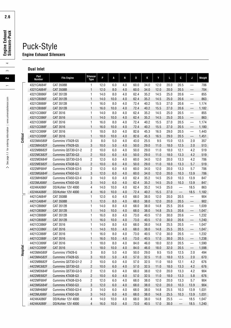
Puck-StyleEngine Exhaust Silencers
PartNumber Fits Engine Silencer
Type P A N D K Y L C J Weight
4321CA684F4321CA884F4321CB886F4321CB086F4321CB888F4321CB088F4321CC886F4321CC086F4321CC888F4321CC088F4321CC899F4321CC099F4323MA580F4323MA582F4322MB682F4322MC682F4322MD684F4322ME682F4322MF684F4323MG684F4323MH686F4323MJ686F4324KA086F4324KA088F4421CA684F4421CA884F4421CB886F4421CB086F4421CB888F4421CB088F4421CC886F4421CC086F4421CC888F4421CC088F4421CC899F4421CC099F4423MA580F4423MA582F4422MB682F4422MC682F4422MD684F4422ME682F4422MF684F4423MG684F4423MH686F4423MJ686F4424KA086F4424KA088F
CAT 3508BCAT 3508BCAT 3512BCAT 3512BCAT 3512BCAT 3512BCAT 3516CAT 3516CAT 3516CAT 3516CAT 3516CAT 3516Cummins VTA28-G5Cummins VTA28-G5Cummins QST30-G1-2Cummins QST30-G3Cummins QST30-G3-5Cummins KTA38-G3Cummins KTA38-G3-5Cummins KTA50-G3Cummins KTA50-G3-4Cummins KTA50-G9DD/Kohler 12V 4000DD/Kohler 12V 4000CAT 3508BCAT 3508BCAT 3512BCAT 3512BCAT 3512BCAT 3512BCAT 3516CAT 3516CAT 3516CAT 3516CAT 3516CAT 3516Cummins VTA28-GCummins VTA28-G5Cummins QST30-G1-2Cummins QST30-G3Cummins QST30-G3-5Cummins KTA38-G3Cummins KTA38-G3-5Cummins KTA50-G3Cummins KTA50-G3-4Cummins KTA50-G9DD/Kohler 12V 4000DD/Kohler 12V 4000
111111111111332222233344111111111111332222233344
12.012.014.014.016.016.014.014.016.016.018.018.08.0
10.010.010.012.010.012.012.014.014.014.016.012.012.014.014.016.016.014.014.016.016.018.018.08.0
10.010.010.012.010.012.012.014.014.014.016.0
6.08.08.0
10.08.0
10.08.0
10.08.0
10.08.0
10.05.05.06.06.06.06.06.06.06.06.0
10.010.06.08.08.0
10.08.0
10.08.0
10.08.0
10.08.0
10.05.05.06.06.06.06.06.06.06.06.0
10.010.0
4.04.04.04.04.04.04.04.04.04.04.04.04.04.04.04.04.04.04.04.04.04.04.04.04.04.04.04.04.04.04.04.04.04.04.04.04.04.04.04.04.04.04.04.04.04.04.04.0
60.060.062.462.472.472.462.462.472.472.482.682.643.050.050.050.060.050.060.060.062.462.462.472.468.068.068.068.073.073.068.068.073.073.084.084.050.057.057.057.068.057.068.068.068.068.068.073.0
34.034.035.235.240.240.235.235.240.240.245.345.325.529.029.029.034.029.034.034.035.235.235.240.238.038.038.038.040.540.538.038.040.540.546.046.029.032.532.532.538.032.538.038.038.038.038.040.5
12.012.014.514.515.515.514.514.515.515.516.516.59.5
11.011.011.012.011.012.012.014.514.514.515.512.012.014.814.817.017.014.814.817.017.018.018.09.5
11.011.011.012.011.012.012.014.814.814.817.0
20.020.025.025.027.027.025.025.027.027.029.029.015.018.018.018.020.018.020.020.025.025.025.027.020.020.025.525.530.030.025.525.530.030.032.032.015.018.018.018.020.018.020.020.025.525.525.530.0
20.520.520.620.620.620.620.520.520.520.520.520.512.512.512.113.313.313.313.310.310.310.3——
20.520.520.620.620.620.620.520.520.520.520.520.512.512.512.113.313.313.313.310.310.310.3——
————————————2.02.04.24.24.25.75.7
13.913.913.918.518.5————————————2.02.04.24.24.25.85.7
13.913.913.918.518.5
706704855863
1,1741,182
855863
1,1741,1801,4431,451
357513519519706519706706847847863
1,182904902
1,0391,0471,2321,2401,0471,0471,2321,2381,5901,598
494670676676904676904904
1,0311,0311,0471,240
Dual Inlet
Criti
cal
Hosp
ital
Rota
ry P
ositi
ve
Blow
er S
ilenc
ers
2.7
Engi
ne E
xhau
stSi
lenc
ers-
Puck
24
3
2.7
See
page
1.1
for
ord
erin
g in
form
atio
n |
ww
w.u
nive
rsal
sile
ncer
.com
1
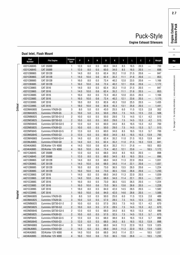
Puck-StyleEngine Exhaust Silencers
PartNumber Fits Engine Silencer
Type P A N D K Y L C J Weight
4321CA684S4321CA884S4321CB886S4321CB086S4321CB888S4321CB088S4321CC886S4321CC086S4321CC888S4321CC088S4321CC899S4321CC099S4323MA580S4323MA582S4322MB682S4322MC682S4322MD684S4322ME682S4322MF684S4323MG684S4323MH686S4323MJ686S4324KA086S4324KA088S4421CA684S4421CA884S4421CB886S4421CB086S4421CB888S4421CB088S4421CC886S4421CC086S4421CC888S4421CC088S4421CC899S4421CC099S4423MA580S4423MA582S4422MB682S4422MC682S4422MD684S4422ME682S4422MF684S4423MG684S4423MH686S4423MJ686S4424KA086S4424KA088S
CAT 3508BCAT 3508BCAT 3512BCAT 3512BCAT 3512BCAT 3512BCAT 3516CAT 3516CAT 3516CAT 3516CAT 3516CAT 3516Cummins VTA28-G5Cummins VTA28-G5Cummins QST30-G1-2Cummins QST30-G3Cummins QST30-G3-5Cummins KTA38-G3Cummins KTA38-G3-5Cummins KTA50-G3Cummins KTA50-G3-4Cummins KTA50-G9DD/Kohler 12V 4000DD/Kohler 12V 4000CAT 3508BCAT 3508BCAT 3512BCAT 3512BCAT 3512BCAT 3512BCAT 3516CAT 3516CAT 3516CAT 3516CAT 3516CAT 3516Cummins VTA28-G5Cummins VTA28-G5Cummins QST30-G1-2Cummins QST30-G3Cummins QST30-G3-5Cummins KTA38-G3Cummins KTA38-G3-5Cummins KTA50-G3Cummins KTA50-G3-4Cummins KTA50-G9DD/Kohler 12V 4000DD/Kohler 12V 4000
111111111111332222233344111111111111332222233344
12.012.014.014.016.016.014.014.016.016.018.018.08.0
10.010.010.012.010.012.012.014.014.014.016.012.012.014.014.016.016.014.014.016.016.018.018.08.0
10.010.010.012.010.012.012.014.014.014.016.0
6.08.08.0
10.08.0
10.08.0
10.08.0
10.08.0
10.05.05.06.06.06.06.06.06.06.06.0
10.010.06.08.08.0
10.08.0
10.08.0
10.08.0
10.08.0
10.05.05.06.06.06.06.06.06.06.06.0
10.010.0
0.50.50.50.60.50.60.50.60.50.60.50.60.50.50.50.50.50.50.50.50.50.50.60.60.50.50.50.60.50.60.50.60.50.60.50.60.50.50.50.50.50.50.50.50.50.50.60.6
60.060.062.462.472.472.462.462.472.472.482.682.643.050.050.050.060.050.060.060.062.462.462.472.468.068.068.068.073.073.068.068.073.073.084.084.050.057.057.057.068.057.068.068.068.068.068.073.0
34.034.035.235.240.240.235.235.240.240.245.345.325.529.029.029.034.029.034.034.035.235.235.240.234.034.034.034.036.536.534.034.036.536.542.042.025.028.528.528.534.032.538.034.034.034.034.036.5
8.58.511.011.112.012.111.011.112.012.113.013.16.07.57.57.58.57.58.58.511.011.011.112.18.58.511.311.413.513.611.311.413.513.614.514.66.07.57.57.58.57.58.58.511.311.311.413.6
16.516.521.521.623.523.621.521.623.523.625.525.611.514.514.514.516.514.516.516.521.521.521.623.616.516.522.022.126.526.622.022.126.526.628.528.611.514.514.514.516.514.516.516.522.022.022.126.6
20.520.520.620.620.620.620.520.520.520.520.520.512.512.512.113.313.313.313.310.310.310.3——
20.520.520.620.620.620.620.520.520.520.520.520.512.512.512.113.313.313.313.310.310.310.3——
————————————2.02.04.24.24.25.75.7
13.913.913.918.518.5————————————2.02.04.24.24.25.75.7
13.913.913.918.518.5
700698847853
1,1661,172
847853
1,1661,1701,4351,441
352508513513700513700700841841853
1,172898896
1,0311,0371,2241,2301,0391,0371,2241,2281,5821,588
489665670670898670898898
1,0251,0251,0371,230
Dual Inlet, Flush Mount
Criti
cal
Hosp
ital

Rota
ry P
ositi
ve
Blow
er S
ilenc
ers
2.8
Engi
ne E
xhau
stSi
lenc
ers-
Puck
43
2.8
See
page
1.1
for
ord
erin
g in
form
atio
n |
ww
w.u
nive
rsal
sile
ncer
.com
21
Puck-StyleEngine Exhaust Silencers
PartNumber Fits Engine Silencer
Type P A N D K Y L C J Weight
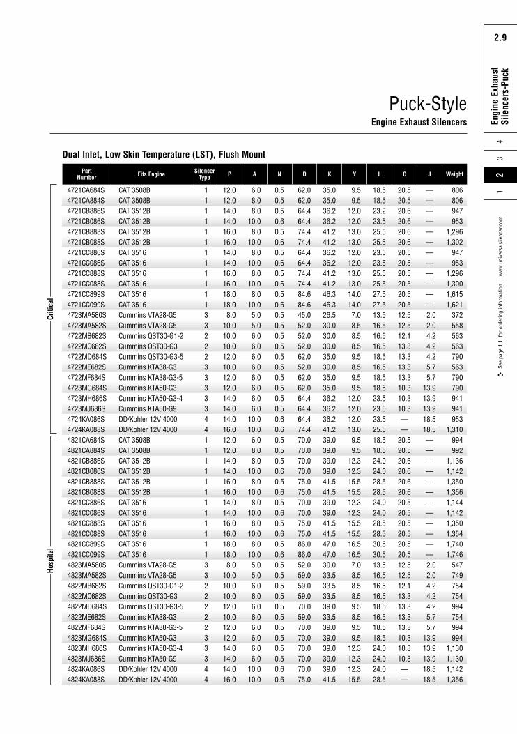
4721CA684F4721CA884F4721CB886F4721CB086F4721CB888F4721CB088F4721CC886F4721CC086F4721CC888F4721CC088F4721CC899F4721CC099F4723MA580F4723MA582F4722MB682F4722MC682F4722MD684F4722ME682F4722MF684F4723MG684F4723MH686F4723MJ686F4724KA086F4724KA088F4821CA684F4821CA884F4821CB886F4821CB086F4821CB888F4821CB088F4821CC886F4821CC086F4821CC888F4821CC088F4821CC899F4821CC099F4823MA580F4823MA582F4822MB682F4822MC682F4822MD684F4822ME682F4822MF684F4823MG684F4823MH686F4823MJ686F4824KA086F4824KA088F
CAT 3508BCAT 3508BCAT 3512BCAT 3512BCAT 3512BCAT 3512BCAT 3516CAT 3516CAT 3516CAT 3516CAT 3516CAT 3516Cummins VTA28-G5Cummins VTA28-G5Cummins QST30-G1-2Cummins QST30-G3Cummins QST30-G3-5Cummins KTA38-G3Cummins KTA38-G3-5Cummins KTA50-G3Cummins KTA50-G3-4Cummins KTA50-G9DD/Kohler 12V 4000DD/Kohler 12V 4000CAT 3508BCAT 3508BCAT 3512BCAT 3512BCAT 3512BCAT 3512BCAT 3516CAT 3516CAT 3516CAT 3516CAT 3516CAT s3516Cummins VTA28-G5Cummins VTA28-G5Cummins QST30-G1-2Cummins QST30-G3Cummins QST30-G3-5Cummins KTA38-G3Cummins KTA38-G3-5Cummins KTA50-G3Cummins KTA50-G3-4Cummins KTA50-G9DD/Kohler 12V 4000DD/Kohler 12V 4000
111111111111332222233344111111111111332222233344
1212141416161414161618188
10101012101212141414161212141416161414161618188
1010101210121214141416
688
108
108
108
108
105566666666
1010688
108
108
108
108
105566666666
1010
4.04.04.04.04.04.04.04.04.04.04.04.04.04.04.04.04.04.04.04.04.04.04.04.04.04.04.04.04.04.04.04.04.04.04.04.04.04.04.04.04.04.04.04.04.04.04.04.0
62.062.064.464.474.474.464.464.474.474.484.684.645.052.052.052.062.052.060.062.064.464.464.474.470.070.070.070.075.075.070.070.075.075.086.086.052.059.059.059.070.059.070.070.070.070.070.075.0
35.035.036.236.241.241.236.236.241.241.246.346.326.530.030.030.035.030.035.035.036.236.236.241.239.039.039.039.041.541.539.039.041.541.547.047.030.033.533.533.539.033.539.039.039.039.039.041.5
13.013.015.015.516.516.515.515.516.516.517.517.510.512.012.012.013.012.013.013.015.515.515.516.513.013.015.815.818.018.015.815.818.018.019.019.010.512.012.012.013.012.013.013.015.815.815.818.0
22.022.027.027.029.029.027.027.029.029.031.031.017.020.020.020.022.020.022.022.027.027.027.029.022.022.027.527.532.032.027.527.532.032.034.034.017.020.020.020.022.020.022.022.027.527.527.532.0
20.520.520.620.620.620.620.520.520.520.520.520.512.512.512.113.313.313.313.310.310.310.3——
20.520.520.620.620.620.620.520.520.520.520.520.512.512.512.113.313.313.313.310.310.310.3——
————————————2.02.04.24.24.25.75.7
13.913.913.918.518.5————————————2.02.04.24.24.25.75.7
13.913.913.918.518.5
796790955963
1,3041,312
955963
1,3041,3101,6231,631
377563569569796569796796947947963
1,3121,0001,0001,1441,1521,3581,3661,1521,1521,3581,3641,7481,756
552754760760
1,000760
1,0001,0001,1361,1361,1521,366
Dual Inlet, Low Skin Temperature (LST)
Criti
cal
Hosp
ital
Rota
ry P
ositi
ve
Blow
er S
ilenc
ers
2.9
Engi
ne E
xhau
stSi
lenc
ers-
Puck
24
3
2.9
See
page
1.1
for
ord
erin
g in
form
atio
n |
ww
w.u
nive
rsal
sile
ncer
.com
1
Puck-StyleEngine Exhaust Silencers
PartNumber Fits Engine Silencer
Type P A N D K Y L C J Weight
4721CA684S4721CA884S4721CB886S4721CB086S4721CB888S4721CB088S4721CC886S4721CC086S4721CC888S4721CC088S4721CC899S4721CC099S4723MA580S4723MA582S4722MB682S4722MC682S4722MD684S4722ME682S4722MF684S4723MG684S4723MH686S4723MJ686S4724KA086S4724KA088S4821CA684S4821CA884S4821CB886S4821CB086S4821CB888S4821CB088S4821CC886S4821CC086S4821CC888S4821CC088S4821CC899S4821CC099S4823MA580S4823MA582S4822MB682S4822MC682S4822MD684S4822ME682S4822MF684S4823MG684S4823MH686S4823MJ686S4824KA086S4824KA088S
CAT 3508BCAT 3508BCAT 3512BCAT 3512BCAT 3512BCAT 3512BCAT 3516CAT 3516CAT 3516CAT 3516CAT 3516CAT 3516Cummins VTA28-G5Cummins VTA28-G5Cummins QST30-G1-2Cummins QST30-G3Cummins QST30-G3-5Cummins KTA38-G3Cummins KTA38-G3-5Cummins KTA50-G3Cummins KTA50-G3-4Cummins KTA50-G9DD/Kohler 12V 4000DD/Kohler 12V 4000CAT 3508BCAT 3508BCAT 3512BCAT 3512BCAT 3512BCAT 3512BCAT 3516CAT 3516CAT 3516CAT 3516CAT 3516CAT 3516Cummins VTA28-G5Cummins VTA28-G5Cummins QST30-G1-2Cummins QST30-G3Cummins QST30-G3-5Cummins KTA38-G3Cummins KTA38-G3-5Cummins KTA50-G3Cummins KTA50-G3-4Cummins KTA50-G9DD/Kohler 12V 4000DD/Kohler 12V 4000
111111111111332223333344111111111111332222233344
12.012.014.014.016.016.014.014.016.016.018.018.08.0
10.010.010.012.010.012.012.014.014.014.016.012.012.014.014.016.016.014.014.016.016.018.018.08.0
10.010.010.012.010.012.012.014.014.014.016.0
6.08.08.0
10.08.0
10.08.0
10.08.0
10.08.0
10.05.05.06.06.06.06.06.06.06.06.0
10.010.06.08.08.0
10.08.0
10.08.0
10.08.0
10.08.0
10.05.05.06.06.06.06.06.06.06.06.0
10.010.0
0.50.50.50.60.50.60.50.60.50.60.50.60.50.50.50.50.50.50.50.50.50.50.60.60.50.50.50.60.50.60.50.60.50.60.50.60.50.50.50.50.50.50.50.50.50.50.60.6
62.062.064.464.474.474.464.464.474.474.484.684.645.052.052.052.062.052.062.062.064.464.464.474.470.070.070.070.075.075.070.070.075.075.086.086.052.059.059.059.070.059.070.070.070.070.070.075.0
35.035.036.236.241.241.236.236.241.241.246.346.326.530.030.030.035.030.035.035.036.236.236.241.239.039.039.039.041.541.539.039.041.541.547.047.030.033.533.533.539.033.539.039.039.039.039.041.5
9.59.5
12.012.013.013.012.012.013.013.014.014.07.08.58.58.59.58.59.59.5
12.012.012.013.09.59.5
12.312.315.515.512.312.315.515.516.516.57.08.58.58.59.58.59.59.5
12.312.312.315.5
18.518.523.223.525.525.523.523.525.525.527.527.513.516.516.516.518.516.518.518.523.523.523.525.518.518.524.024.028.528.524.024.028.528.530.530.513.516.516.516.518.516.518.518.524.024.024.028.5
20.520.520.620.620.620.620.520.520.520.520.520.512.512.512.113.313.313.313.310.310.310.3——
20.520.520.620.620.620.620.520.520.520.520.520.512.512.512.113.313.313.313.310.310.310.3——
————————————2.02.04.24.24.25.75.7
13.913.913.918.518.5————————————2.02.04.24.24.25.75.7
13.913.913.918.518.5
806806947953
1,2961,302
947953
1,2961,3001,6151,621
372558563563790563790790941941953
1,310994992
1,1361,1421,3501,3561,1441,1421,3501,3541,7401,746
547749754754994754994994
1,1301,1301,1421,356
Dual Inlet, Low Skin Temperature (LST), Flush Mount
Criti
cal
Hosp
ital
3Se
e pa
ge 1
.1 f
or o
rder
ing
info
rmat
ion
| w
ww
.uni
vers
alsi
lenc
er.c
om2
14
Rota
ry P
ositi
ve
Blow
er S
ilenc
ers
2.10
Engi
ne E
xhau
stSi
lenc
ers
2.10
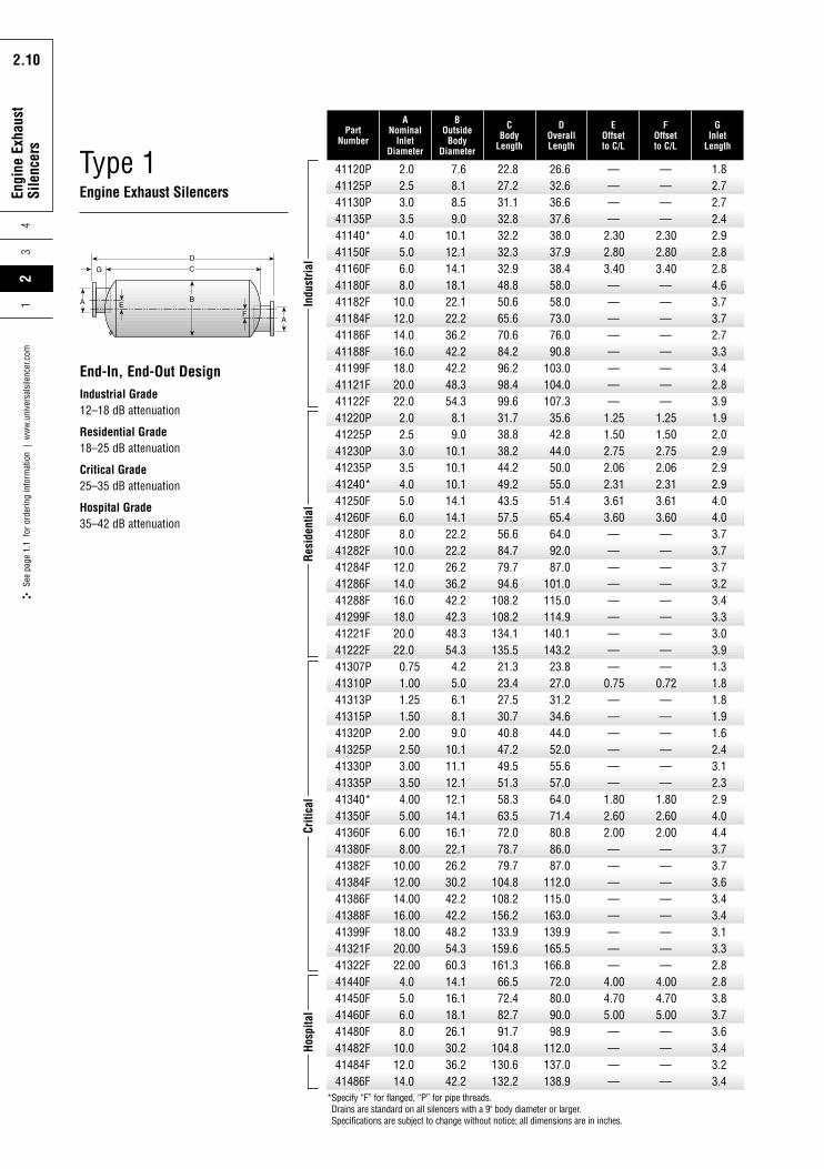
Type 1Engine Exhaust Silencers
41120P41125P41130P41135P41140*41150F41160F41180F41182F41184F41186F41188F41199F41121F41122F41220P41225P41230P41235P41240*41250F41260F41280F41282F41284F41286F41288F41299F41221F41222F41307P41310P41313P41315P41320P41325P41330P41335P41340*41350F41360F41380F41382F41384F41386F41388F41399F41321F41322F41440F41450F41460F41480F41482F41484F41486F
2.02.53.03.54.05.06.08.0
10.012.014.016.018.020.022.02.02.53.03.54.05.06.08.0
10.012.014.016.018.020.022.00.751.001.251.502.002.503.003.504.005.006.008.00
10.0012.0014.0016.0018.0020.0022.004.05.06.08.0
10.012.014.0
7.68.18.59.0
10.112.114.118.122.122.236.242.242.248.354.38.19.0
10.110.110.114.114.122.222.226.236.242.242.348.354.34.25.06.18.19.0
10.111.112.112.114.116.122.126.230.242.242.248.254.360.314.116.118.126.130.236.242.2
22.827.231.132.832.232.332.948.850.665.670.684.296.298.499.631.738.838.244.249.243.557.556.684.779.794.6
108.2108.2134.1135.521.323.427.530.740.847.249.551.358.363.572.078.779.7
104.8108.2156.2133.9159.6161.366.572.482.791.7
104.8130.6132.2
26.632.636.637.638.037.938.458.058.073.076.090.8
103.0104.0107.335.642.844.050.055.051.465.464.092.087.0
101.0115.0114.9140.1143.223.827.031.234.644.052.055.657.064.071.480.886.087.0
112.0115.0163.0139.9165.5166.872.080.090.098.9
112.0137.0138.9
————
2.302.803.40————————
1.251.502.752.062.313.613.60—————————
0.75——————
1.802.602.00————————
4.004.705.00————
————
2.302.803.40————————
1.251.502.752.062.313.613.60—————————
0.72——————
1.802.602.00————————
4.004.705.00————
1.82.72.72.42.92.82.84.63.73.72.73.33.42.83.91.92.02.92.92.94.04.03.73.73.73.23.43.33.03.91.31.81.81.91.62.43.12.32.94.04.43.73.73.63.43.43.13.32.82.83.83.73.63.43.23.4
PartNumber
ANominal
InletDiameter
BOutside
BodyDiameter
CBody
Length
DOverallLength
EOffsetto C/L
FOffsetto C/L
GInlet
Length
Indu
stria
lRe
side
ntia
lCr
itica
lHo
spita
l
*Specify “F” for flanged, “P” for pipe threads. Drains are standard on all silencers with a 9" body diameter or larger.Specifications are subject to change without notice; all dimensions are in inches.
End-In, End-Out DesignIndustrial Grade12–18 dB attenuation
Residential Grade18–25 dB attenuation
Critical Grade25–35 dB attenuation
Hospital Grade35–42 dB attenuation
23
See
page
1.1
for
ord
erin
g in
form
atio
n |
ww
w.u
nive
rsal
sile
ncer
.com
14
Rota
ry P
ositi
ve
Blow
er S
ilenc
ers
2.11
Engi
ne E
xhau
stSi
lenc
ers
2.11
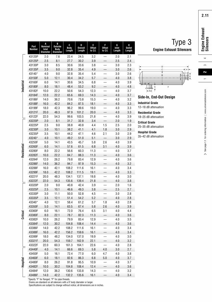
43120P43125P43130P43135P43140*43150F43160F43180F43182F43184F43186F43188F43199F43121F43122F43220P43225P43230P43235P43240*43250F43260F43280F43282F43284F43286F43288F43299F43221F43222F43320P43325P43330P43335P43340*43350F43360F43380F43382F43384F43386F43388F43399F43321F43322F43440F43450F43460F43480F43482F43484F43486F
2.02.53.03.54.05.06.08.0
10.012.014.016.018.020.022.02.02.53.03.54.05.06.08.0
10.012.014.016.018.020.022.02.02.53.03.54.05.06.08.0
10.012.014.016.018.020.022.04.05.06.08.0
10.012.014.0
7.68.18.59.09.0
12.114.118.122.222.236.242.242.348.354.38.19.0
10.110.110.114.114.122.222.226.236.242.142.248.354.39.0
10.111.112.112.114.116.122.126.230.242.242.248.254.360.314.116.118.126.230.236.242.2
22.427.730.632.832.830.430.648.450.665.670.684.296.297.999.631.738.838.244.249.243.557.656.684.779.894.7
108.2108.2134.1135.640.846.650.051.458.463.572.078.779.9
104.8108.2156.2134.0159.7161.366.672.482.691.8
104.8130.6132.2
24.530.233.635.435.434.234.553.254.369.373.887.599.6
101.2103.532.840.841.147.151.045.761.560.388.383.497.9
111.6111.5137.1139.442.449.352.854.261.267.476.482.383.4
108.4111.6159.6137.0162.9164.169.377.086.395.5
108.4133.8135.6
3.23.93.84.95.45.76.89.2
12.314.315.318.119.020.021.83.44.44.14.65.15.86.8
11.311.312.915.316.119.119.821.83.93.84.55.25.75.86.5
11.312.914.416.116.119.922.122.65.86.06.8
10.912.414.316.1
————————————————1.51.82.1—2.63.1————————————1.82.63.1————————4.04.75.0————
2.02.53.03.03.04.04.04.04.04.04.04.04.04.04.02.02.53.03.03.04.04.04.04.04.04.04.04.04.04.02.02.53.04.04.04.04.04.04.04.04.04.04.04.04.03.04.04.04.04.04.04.0
2.12.42.32.62.63.83.94.83.73.73.23.33.33.33.91.92.02.92.92.93.93.93.73.63.63.23.43.33.03.81.62.72.82.82.83.94.43.63.53.63.43.43.03.22.82.73.83.73.73.63.23.4
PartNumber
ANominal
InletDiameter
BOutside
BodyDiameter
CBody
Length
DOverallLength
EOffsetto C/L
FOffsetto C/L
GInlet
Length
HOutletLength
Indu
stria
lRe
side
ntia
lCr
itica
lHo
spita
l
*Specify “F” for flanged, “P” for pipe threads. Drains are standard on all silencers with a 9" body diameter or larger.Specifications are subject to change without notice; all dimensions are in inches.
F
F
G
H
Type 3Engine Exhaust Silencers
Side-In, End-Out DesignIndustrial Grade12–18 dB attenuation
Residential Grade18–25 dB attenuation
Critical Grade25–35 dB attenuation
Hospital Grade35–42 dB attenuation
Rota
ry P
ositi
ve
Blow
er S
ilenc
ers
2.12
Engi
ne E
xhau
stSi
lenc
ers
43
2.12
See
page
1.1
for
ord
erin
g in
form
atio
n |
ww
w.u
nive
rsal
sile
ncer
.com
21
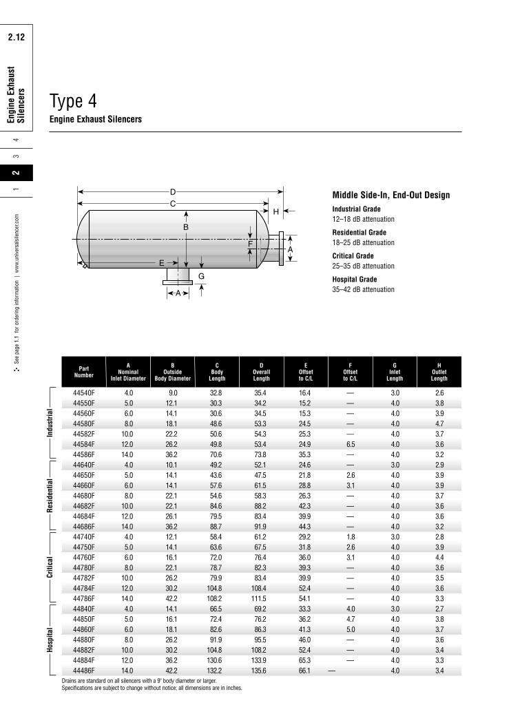
44540F44550F44560F44580F44582F44584F44586F44640F44650F44660F44680F44682F44684F44686F44740F44750F44760F44780F44782F44784F44786F44840F44850F44860F44880F44882F44884F44486F
4.05.06.08.0
10.012.014.04.05.06.08.0
10.012.014.04.05.06.08.0
10.012.014.04.05.06.08.0
10.012.014.0
9.012.114.118.122.226.236.210.114.114.122.122.126.136.212.114.116.122.126.230.242.214.116.118.126.230.236.242.2
32.830.330.648.650.649.870.649.243.657.654.684.679.588.758.463.672.078.779.9
104.8108.266.572.482.691.9
104.8130.6132.2
35.434.234.553.354.353.473.852.147.561.558.388.283.491.961.267.576.482.383.4
108.4111.569.276.286.395.5
108.2133.9135.6
16.415.215.324.525.324.935.324.621.828.826.342.339.944.329.231.836.039.339.952.454.133.336.241.346.052.465.366.1
—————6.5——2.63.1————1.82.63.1————4.04.75.0———
—
3.04.04.04.04.04.04.03.04.04.04.04.04.04.03.04.04.04.04.04.04.03.04.04.04.04.04.04.0
2.63.83.94.73.73.63.22.93.93.93.73.63.63.22.83.94.43.63.53.63.32.73.83.73.63.43.33.4
PartNumber
ANominal
Inlet Diameter
BOutside
Body Diameter
CBody
Length
DOverallLength
EOffsetto C/L
FOffsetto C/L
GInlet
Length
HOutletLength
Drains are standard on all silencers with a 9" body diameter or larger.Specifications are subject to change without notice; all dimensions are in inches.
Indu
stria
lRe
side
ntia
lCr
itica
lHo
spita
l
Type 4Engine Exhaust Silencers
Middle Side-In, End-Out DesignIndustrial Grade12–18 dB attenuation
Residential Grade18–25 dB attenuation
Critical Grade25–35 dB attenuation
Hospital Grade35–42 dB attenuation
Rota
ry P
ositi
ve
Blow
er S
ilenc
ers
2.13
Engi
ne E
xhau
stSi
lenc
ers
24
3
2.13
See
page
1.1
for
ord
erin
g in
form
atio
n |
ww
w.u
nive
rsal
sile
ncer
.com
1
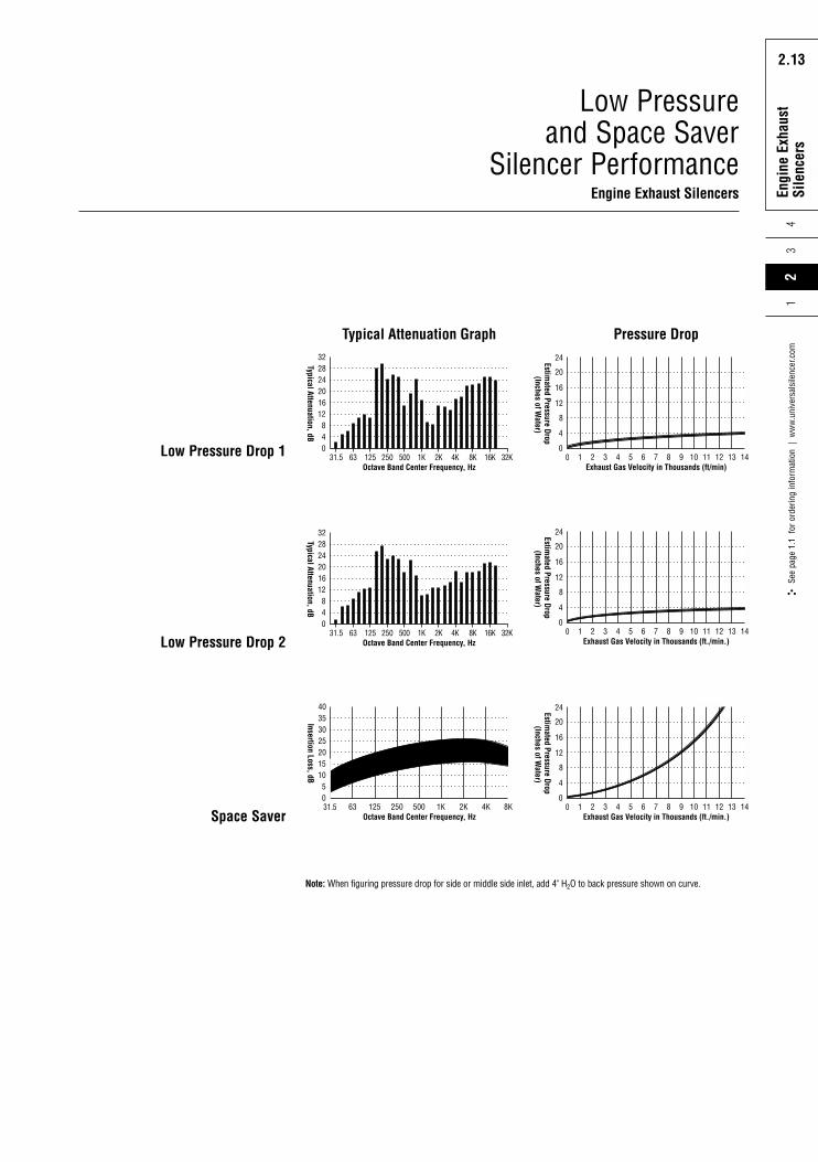
Low Pressure and Space Saver
Silencer PerformanceEngine Exhaust SilencersEx
haus
t Sile
ncer
s
31.5 63 125 250 500 1K 2K 4K 8K 16K 32KOctave Band Center Frequency, Hz
Typical Attenuation, dB
32
48
12
0
16202428
Typical Attenuation Graph24
0 1 2 3 4 5 6 7 8 9 10 11 12 13 14
4
0
8
12
16
20
Exhaust Gas Velocity in Thousands (ft/min)
Estimated Pressure Drop
(Inches of Water)
Pressure Drop
31.5 63 125 250 500 1K 2K 4K 8K 16K 32KOctave Band Center Frequency, Hz
Typical Attenuation, dB
32
48
12
0
16202428
24
0 1 2 3 4 5 6 7 8 9 10 11 12 13 14
4
0
8
12
16
20
Exhaust Gas Velocity in Thousands (ft./min.)
Estimated Pressure Drop
(Inches of Water)
40
31.5 63 125 250 500 1K 2K 4K 8K
51015
0
20253035
Octave Band Center Frequency, Hz
Insertion Loss, dB
24
0 1 2 3 4 5 6 7 8 9 10 11 12 13 14
4
0
8
12
16
20
Exhaust Gas Velocity in Thousands (ft./min.)
Estimated Pressure Drop
(Inches of Water)
Low Pressure Drop 2
Space Saver
Low Pressure Drop 1
Note: When figuring pressure drop for side or middle side inlet, add 4" H2O to back pressure shown on curve.
3Se
e pa
ge 1
.1 f
or o
rder
ing
info
rmat
ion
| w
ww
.uni
vers
alsi
lenc
er.c
om2
14
Rota
ry P
ositi
ve
Blow
er S
ilenc
ers
2.14
Engi
ne E
xhau
stSi
lenc
ers
2.14
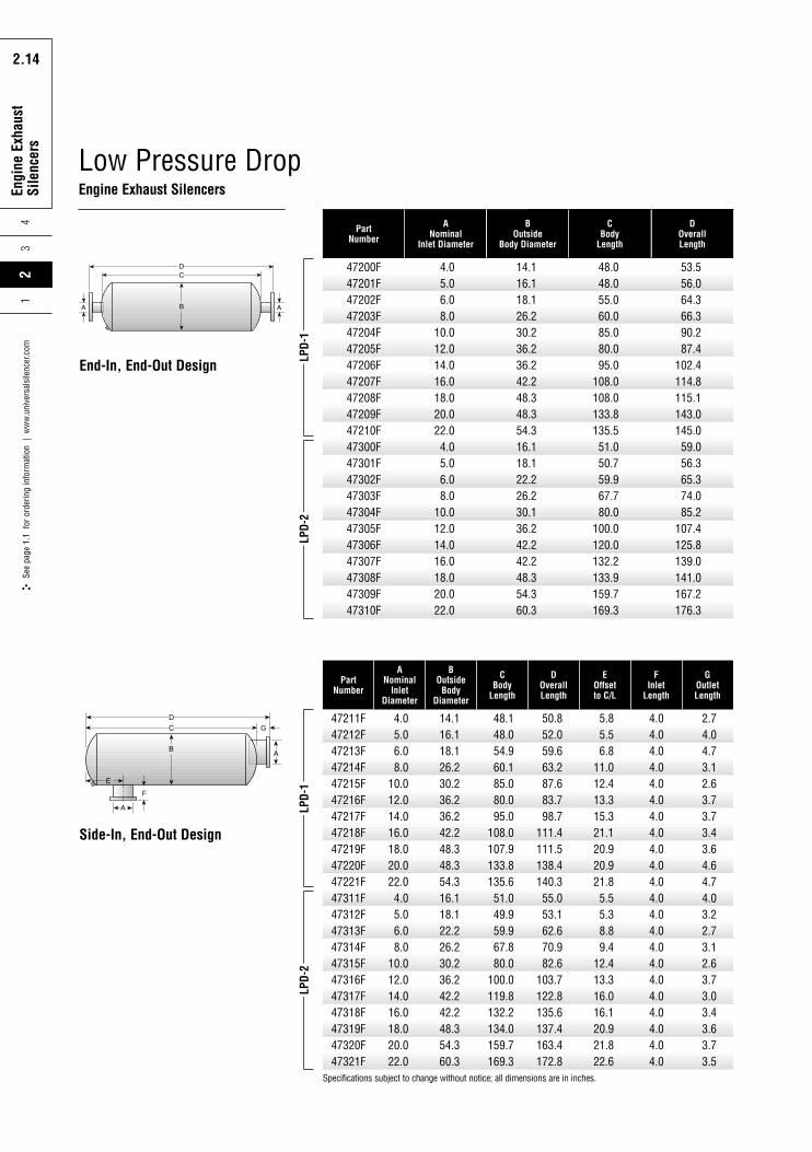
Low Pressure DropEngine Exhaust Silencers
47200F47201F47202F47203F47204F47205F47206F47207F47208F47209F47210F47300F47301F47302F47303F47304F47305F47306F47307F47308F47309F47310F
4.05.06.08.0
10.012.014.016.018.020.022.04.05.06.08.0
10.012.014.016.018.020.022.0
14.116.118.126.230.236.236.242.248.348.354.316.118.122.226.230.136.242.242.248.354.360.3
48.048.055.060.085.080.095.0
108.0108.0133.8135.551.050.759.967.780.0
100.0120.0132.2133.9159.7169.3
PartNumber
ANominal
Inlet Diameter
BOutside
Body Diameter
CBody
Length
53.556.064.366.390.287.4
102.4114.8115.1143.0145.059.056.365.374.085.2
107.4125.8139.0141.0167.2176.3
DOverallLength
LPD-
1LP
D-2
47211F47212F47213F47214F47215F47216F47217F47218F47219F47220F47221F47311F47312F47313F47314F47315F47316F47317F47318F47319F47320F47321F
4.05.06.08.0
10.012.014.016.018.020.022.04.05.06.08.0
10.012.014.016.018.020.022.0
14.116.118.126.230.236.236.242.248.348.354.316.118.122.226.230.236.242.242.248.354.360.3
48.148.054.960.185.080.095.0
108.0107.9133.8135.651.049.959.967.880.0
100.0119.8132.2134.0159.7169.3
50.852.059.663.287.683.798.7
111.4111.5138.4140.355.053.162.670.982.6
103.7122.8135.6137.4163.4172.8
5.85.56.8
11.012.413.315.321.120.920.921.85.55.38.89.4
12.413.316.016.120.921.822.6
4.04.04.04.04.04.04.04.04.04.04.04.04.04.04.04.04.04.04.04.04.04.0
2.74.04.73.12.63.73.73.43.64.64.74.03.22.73.12.63.73.03.43.63.73.5
PartNumber
ANominal
InletDiameter
BOutside
BodyDiameter
CBody
Length
DOverallLength
EOffsetto C/L
FInlet
Length
GOutletLength
LPD-
1LP
D-2
Specifications subject to change without notice; all dimensions are in inches.
F
G
End-In, End-Out Design
Side-In, End-Out Design
Rota
ry P
ositi
ve
Blow
er S
ilenc
ers
2.15
Engi
ne E
xhau
stSi
lenc
ers
24
3
2.15
See
page
1.1
for
ord
erin
g in
form
atio
n |
ww
w.u
nive
rsal
sile
ncer
.com
1
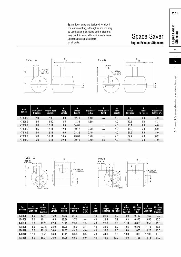
47820S
PartNumber
47825S47830S47835S47840S47850S47860S
2.02.53.03.54.05.06.0
7.008.50
12.1112.1112.1116.1116.11
8.08.59.3
12.016.016.522.0
12.7013.3314.6519.4223.3223.8929.49
1.101.60
—2.702.403.702.50
——————
1.5
4.04.04.04.04.04.04.0
12.012.513.118.021.922.428.0
4.04.03.96.05.95.96.0
4.04.34.66.08.08.2
11.0
AInlet-OutletDiameter
BOutside Body
Diameter
CBody
Length
DOverallLength
EInlet Offset
to C/L
FOutlet Offset
to C/L
GInlet
Length
HLength
to Flange
IFlange
to Flange
JOffset Seamto Inlet C/L
47840F
PartNumber
47850F47860F47880F47882F47884F47886F
4.05.06.08.0
10.012.014.0
12.1116.1116.1122.1526.1530.2136.21
16.016.522.025.030.036.036.0
23.3223.8929.4936.2841.8748.4151.29
2.403.702.504.504.423.586.50
——1.53.44.03.55.0
4.04.04.04.04.04.04.0
21.922.428.033.038.044.046.0
5.95.96.08.08.08.0
10.0
8.08.3
11.012.515.018.018.0
AInlet-OutletDiameter
BOutsideBody
Diameter
CBody
Length
DOverallLength
EInlet Offset
to C/L
FOutletOffsetto C/L
GInlet
Length
HLength
to Flange
IFlange
to Flange
JOffset
Seam toInlet C/L
0.7500.8750.8750.8751.0001.0001.125
KMounting
FlangeBolt
7.508.509.50
11.7514.2517.0018.78
LBolt HoleDiameter
9.010.011.013.516.019.021.0
MMounting
FlangeDiameter
Space Saver units are designed for side-inend-out mounting, although either end maybe used as an inlet. Using end-in side-outmay result in lower attenuation reductions.Condensate drains standardon all units.
Space SaverEngine Exhaust Silencers
Rota
ry P
ositi
ve
Blow
er S
ilenc
ers
2.16
Engi
ne E
xhau
stSi
lenc
ers
43
2.16
See
page
1.1
for
ord
erin
g in
form
atio
n |
ww
w.u
nive
rsal
sile
ncer
.com
21
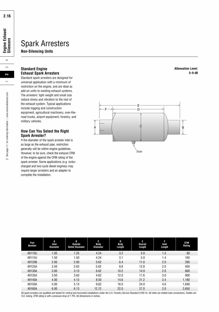
Standard EngineExhaust Spark ArrestersStandard spark arresters are designed foruniversal application with a minimum ofrestriction on the engine, and are ideal asadd-on units to existing exhaust systems.The arresters’ light weight and small sizereduce stress and vibration to the rest ofthe exhaust system. Typical applicationsinclude logging and constructionequipment, agricultural machinery, over-the-road trucks, airport equipment, forestry, andmilitary vehicles.
How Can You Select the RightSpark Arrester?If the diameter of the spark arrester inlet isas large as the exhaust pipe, restrictiongenerally will be within engine guidelines.However, to be sure, check the exhaust CFMof the engine against the CFM rating of thespark arrester. Some applications (e.g. turbo-charged and two-cycle diesel engines) mayrequire larger arresters and an adapter tocomplete the installation.
49110U49115U49120B49125A49130A49135A49140A49150A49160A
1.051.502.002.503.003.504.005.006.00
1.251.502.002.633.133.634.135.136.13
4.244.245.625.626.624.628.509.62
12.12
3.23.16.48.6
10.212.014.616.022.0
5.95.9
11.012.814.917.621.224.027.0
1.31.42.02.02.03.03.44.02.0
80165295450660900
1,1801,8402,650
PartNumber
AInlet
Diameter
BOutside
Outlet Diameter
CBody
Diameter
DBody
Length
EOverallLength
FInlet
Length
CFMRating
All spark arresters are qualified and tested for vertical and horizontal installations under the U.S. Forestry Service Standard 5100-1b. All inlets are slotted tube connections. Outlets areO.D. tubing. CFM rating is with a pressure drop of 1 PSI. All dimensions in inches.
Drain
Attenuation Level:5–9 dB
Spark ArrestersNon-Silencing Units
Rota
ry P
ositi
ve
Blow
er S
ilenc
ers
2.17
Engi
ne E
xhau
stSi
lenc
ers
24
3
2.17
See
page
1.1
for
ord
erin
g in
form
atio
n |
ww
w.u
nive
rsal
sile
ncer
.com
1
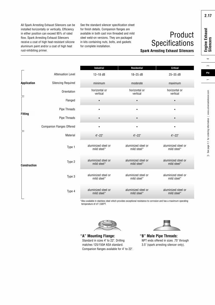
ProductSpecifications
Spark Arresting Exhaust Silencers
12–18 dB 18–25 dB 25–35 dB
minimum moderate maximum
•
4"–22" 4"–22" 4"–22"
aluminized steel ormild steel*
aluminized steel ormild steel*
aluminized steel ormild steel*
aluminized steel ormild steel*
aluminized steel ormild steel*
aluminized steel ormild steel*
aluminized steel ormild steel*
aluminized steel ormild steel*
aluminized steel ormild steel*
aluminized steel ormild steel*
aluminized steel ormild steel*
aluminized steel ormild steel*
• •
Residential Critical
Attenuation Level
Silencing Required
horizontal orvertical
horizontal orvertical
horizontal orvertical
Orientation
Flanged
• • •Companion Flanges Offered
• • •Pipe Threads
• • •Pipe Threads
Type 1
Type 2
Type 3
Type 4
Material
Industrial
Application
Fitting
Construction
All Spark Arresting Exhaust Silencers can beinstalled horizontally or vertically. Efficiencyin either position can exceed 95% of ratedflow. Spark Arresting Exhaust Silencersreceive a coat of high heat-resistant siliconealuminum paint and/or a coat of high heatrust-inhibiting primer.
“A” Mounting Flange:Standard in sizes 4" to 22". Drillingmatches 125/150# ASA standard.Companion flanges available for 4" to 22".
“B” Male Pipe Threads:NPT ends offered in sizes .75" through3.5" (spark arresting silencer only).
*Also available in stainless steel which provides exceptional resistance to corrosion and has a maximum operatingtemperature of of 1,500°F.
See the standard silencer specification sheetfor finish details. Companion flanges areavailable in both cast iron threaded and mildsteel weld-on versions. They are packagedin kits containing nuts, bolts, and gasketsfor complete installation.
Rota
ry P
ositi
ve
Blow
er S
ilenc
ers
2.18
Engi
ne E
xhau
stSi
lenc
ers
43
2.18
See
page
1.1
for
ord
erin
g in
form
atio
n |
ww
w.u
nive
rsal
sile
ncer
.com
21
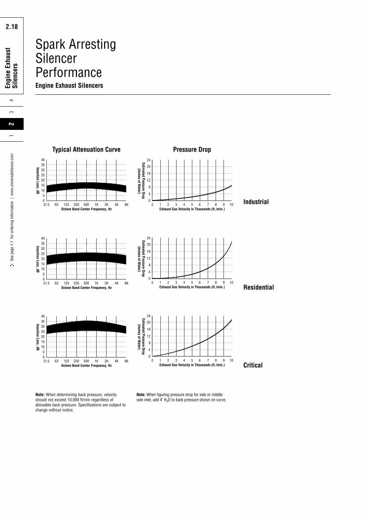
Spark ArrestingSilencerPerformanceEngine Exhaust Silencers
40
31.5 63 125 250 500
51015
0
20253035
Octave Band Center Frequency, Hz
Insertion Loss, dB
1K 2K 4K 8K
Critical
Residential
Typical Attenuation Curve24
0 1 2 3 4 5 6 7 8 9 10
4
0
8
12
16
20
Exhaust Gas Velocity in Thousands (ft./min.)
Estimated Pressure Drop
(Inches of Water)
Pressure Drop
40
31.5 63 125 250 500
51015
0
20253035
Octave Band Center Frequency, Hz
Insertion Loss, dB
1K 2K 4K 8K
Critical
24
0 1 2 3 4 5 6 7 8 9 10
4
0
8
12
16
20
Exhaust Gas Velocity in Thousands (ft./min.)
Estimated Pressure Drop
(Inches of Water)
40
31.5 63 125 250 500
51015
0
20253035
Octave Band Center Frequency, Hz
Insertion Loss, dB
1K 2K 4K 8K
Residential
24
0 1 2 3 4 5 6 7 8 9 10
4
0
8
12
16
20
Exhaust Gas Velocity in Thousands (ft./min.)
Estimated Pressure Drop
(Inches of Water)
Residential
Critical
Industrial
Note: When figuring pressure drop for side or middleside inlet, add 4" H2O to back pressure shown on curve.
Note: When determining back pressure, velocityshould not exceed 10,000 ft/min regardless ofallowable back pressure. Specifications are subject tochange without notice.
Rota
ry P
ositi
ve
Blow
er S
ilenc
ers
2.19
Engi
ne E
xhau
stSi
lenc
ers
24
3
2.19
See
page
1.1
for
ord
erin
g in
form
atio
n |
ww
w.u
nive
rsal
sile
ncer
.com
1
49325U49330U49335U49340U49350U49360U49380U49382U49384U49386U49388U49399U49321U49322U49415U49420U49425U49430U49435U49440U49450U49460U49480U49482U49484U49486U49540U49550U49560U49580U49582U49584U
2.53.03.54.05.06.08.0
10.012.014.016.018.020.022.01.52.02.53.03.54.05.06.08.0
10.012.014.04.05.06.08.0
10.012.0
9.009.009.00
10.1212.1214.1218.1222.1226.1236.2136.1842.1248.1254.127.008.129.63
10.1211.1212.1214.1216.1218.1222.1226.1236.2114.1216.1218.1222.1226.1230.18
21.824.323.823.728.331.548.352.667.772.280.692.2
103.9115.516.420.725.031.233.035.341.545.562.374.686.790.241.547.052.766.672.186.8
25.029.529.131.535.538.056.060.074.077.090.0
100.0109.9123.120.025.030.036.038.042.048.055.072.082.093.095.048.054.062.076.086.192.0
1.92.72.63.93.62.73.83.23.12.44.73.93.03.81.62.12.22.22.93.13.34.54.93.73.12.03.23.85.13.03.42.9
1.92.72.63.93.62.73.83.23.12.44.73.93.03.81.62.12.22.22.93.13.34.54.93.73.12.03.23.85.13.03.42.9
PartNumber
ANominal
Inlet Diameter
BOutside
Body Diameter
CBody
Length
DOverallLength
EInlet
Length
FOutletLength
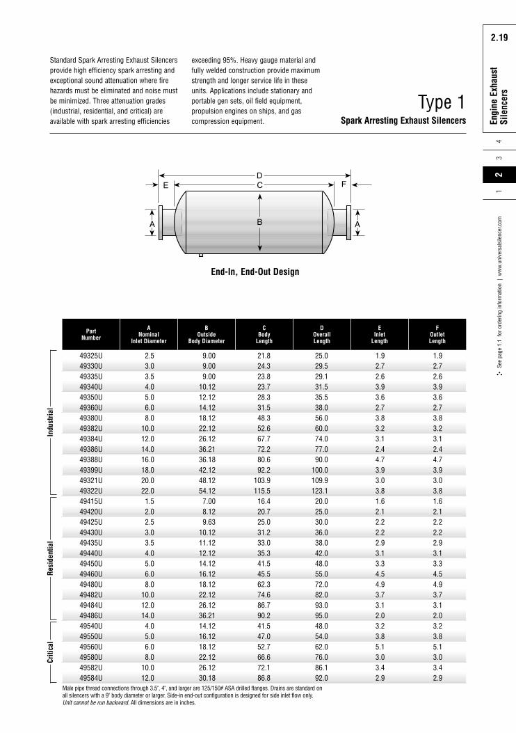
Male pipe thread connections through 3.5", 4", and larger are 125/150# ASA drilled flanges. Drains are standard onall silencers with a 9" body diameter or larger. Side-in end-out configuration is designed for side inlet flow only.Unit cannot be run backward. All dimensions are in inches.
Indu
stria
lRe
side
ntia
lCr
itica
lStandard Spark Arresting Exhaust Silencersprovide high efficiency spark arresting andexceptional sound attenuation where firehazards must be eliminated and noise mustbe minimized. Three attenuation grades(industrial, residential, and critical) areavailable with spark arresting efficiencies
Type 1Spark Arresting Exhaust Silencers
exceeding 95%. Heavy gauge material andfully welded construction provide maximumstrength and longer service life in theseunits. Applications include stationary andportable gen sets, oil field equipment,propulsion engines on ships, and gascompression equipment.
End-In, End-Out Design
Rota
ry P
ositi
ve
Blow
er S
ilenc
ers
2.20
Engi
ne E
xhau
stSi
lenc
ers
43
2.20
See
page
1.1
for
ord
erin
g in
form
atio
n |
ww
w.u
nive
rsal
sile
ncer
.com
21
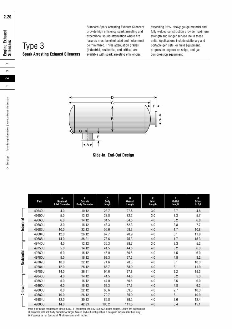
Type 3Spark Arresting Exhaust Silencers
49640U49650U49660U49680U49682U49684U49686U49740U49750U49760U49780U49782U49784U49786U49840U49850U49860U49880U49882U49884U49886U
4.05.06.08.0
10.012.014.04.05.06.08.0
10.012.014.04.05.06.08.0
10.012.014.0
10.1212.1214.1218.1222.1226.1236.2112.1214.1216.1218.1222.1226.1236.2114.1216.1218.1222.1226.1230.1242.23
23.728.831.548.356.667.773.635.341.546.062.374.685.794.641.547.052.366.679.786.8
108.2
27.832.234.852.358.370.975.338.744.850.567.378.388.997.844.850.557.369.385.989.2
111.6
3.03.04.04.04.04.04.03.04.04.04.04.04.04.04.04.04.04.04.04.04.0
3.73.33.23.81.73.11.73.33.24.54.83.13.13.23.23.54.82.76.12.63.4
PartA
NominalInlet Diameter
BOutside
Body Diameter
CBody
Length
DOverallLength
EInlet
Length
FOutletLength
4.85.76.87.7
10.811.915.35.26.36.08.2
10.311.915.35.36.06.2
10.310.912.415.1
GOffsetto C/L
Indu
stria
lRe
side
ntia
lCr
itica
lStandard Spark Arresting Exhaust Silencersprovide high efficiency spark arresting andexceptional sound attenuation where firehazards must be eliminated and noise mustbe minimized. Three attenuation grades(industrial, residential, and critical) areavailable with spark arresting efficiencies
Male pipe thread connections through 3.5", 4", and larger are 125/150# ASA drilled flanges. Drains are standard onall silencers with a 9" body diameter or larger. Side-in end-out configuration is designed for side inlet flow only.Unit cannot be run backward. All dimensions are in inches.
exceeding 95%. Heavy gauge material andfully welded construction provide maximumstrength and longer service life in theseunits. Applications include stationary andportable gen sets, oil field equipment,propulsion engines on ships, and gascompression equipment.
Side-In, End-Out Design
Rota
ry P
ositi
ve
Blow
er S
ilenc
ers
2.21
Engi
ne E
xhau
stSi
lenc
ers
24
3
2.21
See
page
1.1
for
ord
erin
g in
form
atio
n |
ww
w.u
nive
rsal
sile
ncer
.com
1
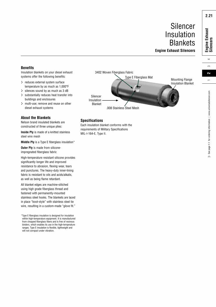
SilencerInsulation
BlanketsEngine Exhaust Silencers
3402 Woven Fiberglass Fabric
.008 Stainless Steel Mesh
Type E Fiberglass MatMounting FlangeInsulation Blanket
SilencerInsulation
Blanket
BenefitsInsulation blankets on your diesel exhaustsystems offer the following benefits:
reduces external system surfacetemperature by as much as 1,000°Fsilences sound by as much as 3 dBsubstantially reduces heat transfer intobuildings and enclosuresmulti-use; remove and reuse on otherdiesel exhaust systems
About the BlanketsNelson brand insulated blankets areconstructed of three unique plies:
Inside Ply is made of a knitted stainlesssteel wire mesh
Middle Ply is a Type E fiberglass insulation*
Outer Ply is made from silicone-impregnated fiberglass fabric
High-temperature resistant silicone providessignificantly longer life and improvedresistance to abrasion, flexing wear, tearsand punctures. The heavy-duty inner-liningfabric is resistant to oils and acids/alkalis,as well as being flame retardant.
All blanket edges are machine-stitchedusing high grade fiberglass thread andfastened with permanently-mountedstainless steel hooks. The blankets are lacedin place “boot-style” with stainless steel tiewire, resulting in a custom-made “glove fit.”
*Type E fiberglass insulation is designed for insulationwithin high-temperature equipment. It is manufacturedfrom chopped fiberglass fibers and is free of resinousbinders, which enables its use in the high-temperatureranges. Type E insulation is flexible, lightweight andwill not compact under vibration.
SpecificationsEach insulation blanket conforms with therequirements of Military Specifications MIL-I-164-E, Type II.
Rota
ry P
ositi
ve
Blow
er S
ilenc
ers
2.22
Engi
ne E
xhau
stSi
lenc
ers
43
2.22
See
page
1.1
for
ord
erin
g in
form
atio
n |
ww
w.u
nive
rsal
sile
ncer
.com
21
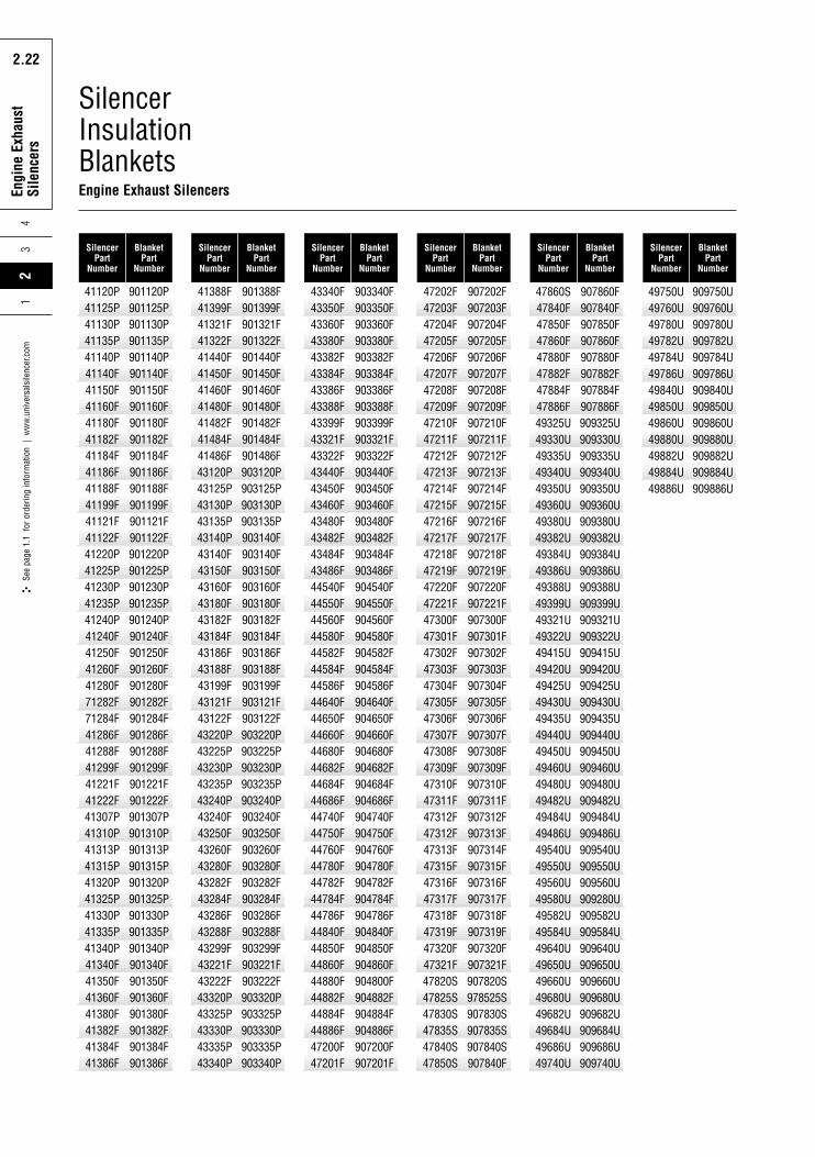
Silencer InsulationBlanketsEngine Exhaust Silencers
SilencerPart
Number
BlanketPart
Number
SilencerPart
Number
BlanketPart
Number
SilencerPart
Number
BlanketPart
Number
SilencerPart
Number
BlanketPart
Number
SilencerPart
Number
BlanketPart
Number
SilencerPart
Number
BlanketPart
Number
41120P41125P41130P41135P41140P41140F41150F41160F41180F41182F41184F41186F41188F41199F41121F41122F41220P41225P41230P41235P41240P41240F41250F41260F41280F71282F71284F41286F41288F41299F41221F41222F41307P41310P41313P41315P41320P41325P41330P41335P41340P41340F41350F41360F41380F41382F41384F41386F
901120P901125P901130P901135P901140P901140F901150F901160F901180F901182F901184F901186F901188F901199F901121F901122F901220P901225P901230P901235P901240P901240F901250F901260F901280F901282F901284F901286F901288F901299F901221F901222F901307P901310P901313P901315P901320P901325P901330P901335P901340P901340F901350F901360F901380F901382F901384F901386F
41388F41399F41321F41322F41440F41450F41460F41480F41482F41484F41486F43120P43125P43130P43135P43140P43140F43150F43160F43180F43182F43184F43186F43188F43199F43121F43122F43220P43225P43230P43235P43240P43240F43250F43260F43280F43282F43284F43286F43288F43299F43221F43222F43320P43325P43330P43335P43340P
901388F901399F901321F901322F901440F901450F901460F901480F901482F901484F901486F903120P903125P903130P903135P903140F903140F903150F903160F903180F903182F903184F903186F903188F903199F903121F903122F903220P903225P903230P903235P903240P903240F903250F903260F903280F903282F903284F903286F903288F903299F903221F903222F903320P903325P903330P903335P903340P
43340F43350F43360F43380F43382F43384F43386F43388F43399F43321F43322F43440F43450F43460F43480F43482F43484F43486F44540F44550F44560F44580F44582F44584F44586F44640F44650F44660F44680F44682F44684F44686F44740F44750F44760F44780F44782F44784F44786F44840F44850F44860F44880F44882F44884F44886F47200F47201F
903340F903350F903360F903380F903382F903384F903386F903388F903399F903321F903322F903440F903450F903460F903480F903482F903484F903486F904540F904550F904560F904580F904582F904584F904586F904640F904650F904660F904680F904682F904684F904686F904740F904750F904760F904780F904782F904784F904786F904840F904850F904860F904800F904882F904884F904886F907200F907201F
47202F47203F47204F47205F47206F47207F47208F47209F47210F47211F47212F47213F47214F47215F47216F47217F47218F47219F47220F47221F47300F47301F47302F47303F47304F47305F47306F47307F47308F47309F47310F47311F47312F47312F47313F47315F47316F47317F47318F47319F47320F47321F47820S47825S47830S47835S47840S47850S
907202F907203F907204F907205F907206F907207F907208F907209F907210F907211F907212F907213F907214F907215F907216F907217F907218F907219F907220F907221F907300F907301F907302F907303F907304F907305F907306F907307F907308F907309F907310F907311F907312F907313F907314F907315F907316F907317F907318F907319F907320F907321F907820S978525S907830S907835S907840S907840F
47860S47840F47850F47860F47880F47882F47884F47886F49325U49330U49335U49340U49350U49360U49380U49382U49384U49386U49388U49399U49321U49322U49415U49420U49425U49430U49435U49440U49450U49460U49480U49482U49484U49486U49540U49550U49560U49580U49582U49584U49640U49650U49660U49680U49682U49684U49686U49740U
907860F907840F907850F907860F907880F907882F907884F907886F909325U909330U909335U909340U909350U909360U909380U909382U909384U909386U909388U909399U909321U909322U909415U909420U909425U909430U909435U909440U909450U909460U909480U909482U909484U909486U909540U909550U909560U909280U909582U909584U909640U909650U909660U909680U909682U909684U909686U909740U
49750U49760U49780U49782U49784U49786U49840U49850U49860U49880U49882U49884U49886U
909750U909760U909780U909782U909784U909786U909840U909850U909860U909880U909882U909884U909886U
Rota
ry P
ositi
ve
Blow
er S
ilenc
ers
2.23
Engi
ne E
xhau
stSi
lenc
ers
24
3
2.23
See
page
1.1
for
ord
erin
g in
form
atio
n |
ww
w.u
nive
rsal
sile
ncer
.com
1
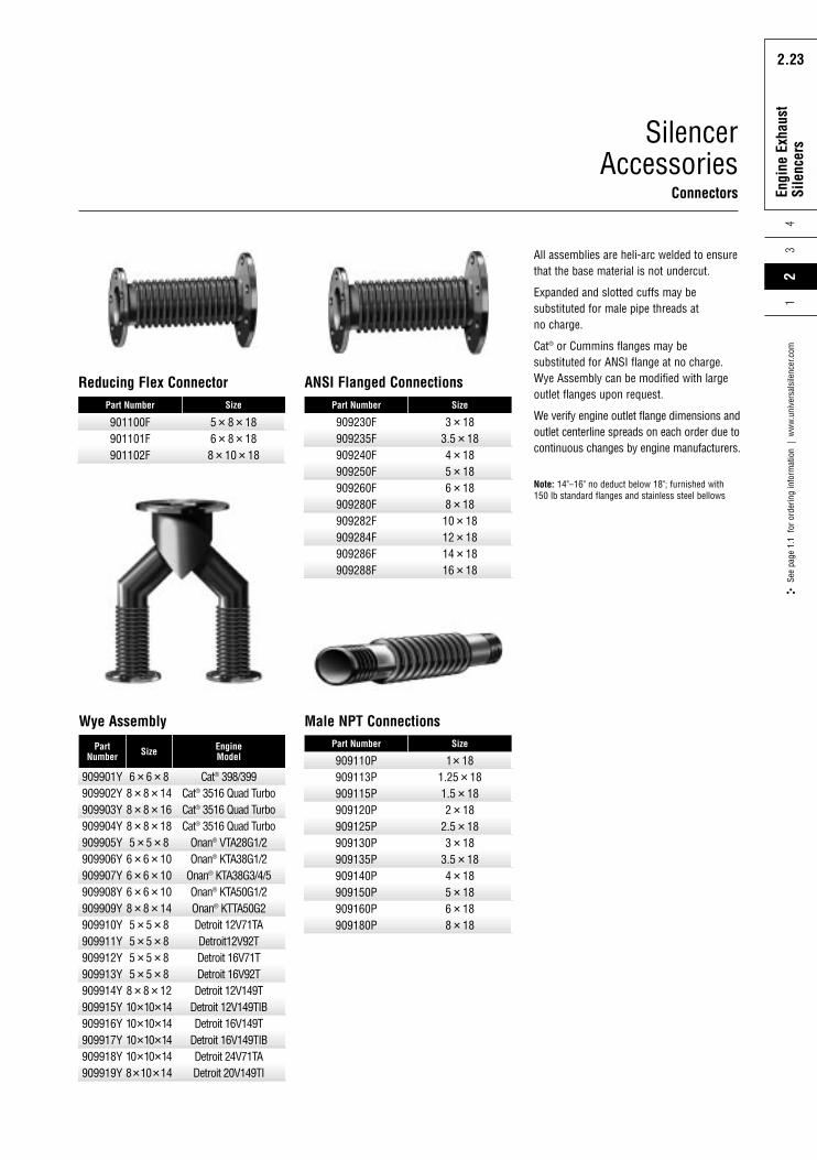
SilencerAccessories
Connectors
909901Y909902Y909903Y909904Y909905Y909906Y909907Y909908Y909909Y909910Y909911Y909912Y909913Y909914Y909915Y909916Y909917Y909918Y909919Y
6�6�88�8�148�8�168�8�185�5�86�6�106�6�106�6�108�8�145�5�85�5�85�5�85�5�88�8�1210�10�1410�10�1410�10�1410�10�148�10�14
PartNumber Size
Cat® 398/399Cat® 3516 Quad TurboCat® 3516 Quad TurboCat® 3516 Quad Turbo
Onan® VTA28G1/2Onan® KTA38G1/2
Onan® KTA38G3/4/5Onan® KTA50G1/2Onan® KTTA50G2Detroit 12V71TADetroit12V92TDetroit 16V71TDetroit 16V92TDetroit 12V149T
Detroit 12V149TIBDetroit 16V149T
Detroit 16V149TIBDetroit 24V71TADetroit 20V149TI
EngineModel
Wye Assembly
901100F901101F901102F
5� 8� 186� 8� 188� 10� 18
Part Number Size
Reducing Flex Connector
909110P909113P909115P909120P909125P909130P909135P909140P909150P909160P909180P
1� 181.25 � 181.5 � 182 � 18
2.5 � 183 � 18
3.5 � 184 � 185 � 186 � 188 � 18
Part Number Size
Male NPT Connections
909230F909235F909240F909250F909260F909280F909282F909284F909286F909288F
3 � 183.5 � 184 � 185 � 186 � 188 � 1810 � 1812 � 1814 � 1816 � 18
Part Number Size
ANSI Flanged Connections
All assemblies are heli-arc welded to ensurethat the base material is not undercut.
Expanded and slotted cuffs may besubstituted for male pipe threads at no charge.
Cat® or Cummins flanges may besubstituted for ANSI flange at no charge.Wye Assembly can be modified with largeoutlet flanges upon request.
We verify engine outlet flange dimensions andoutlet centerline spreads on each order due tocontinuous changes by engine manufacturers.
Note: 14"–16" no deduct below 18"; furnished with 150 lb standard flanges and stainless steel bellows
Rota
ry P
ositi
ve
Blow
er S
ilenc
ers
2.24
Engi
ne E
xhau
stSi
lenc
ers
43
2.24
See
page
1.1
for
ord
erin
g in
form
atio
n |
ww
w.u
nive
rsal
sile
ncer
.com
21
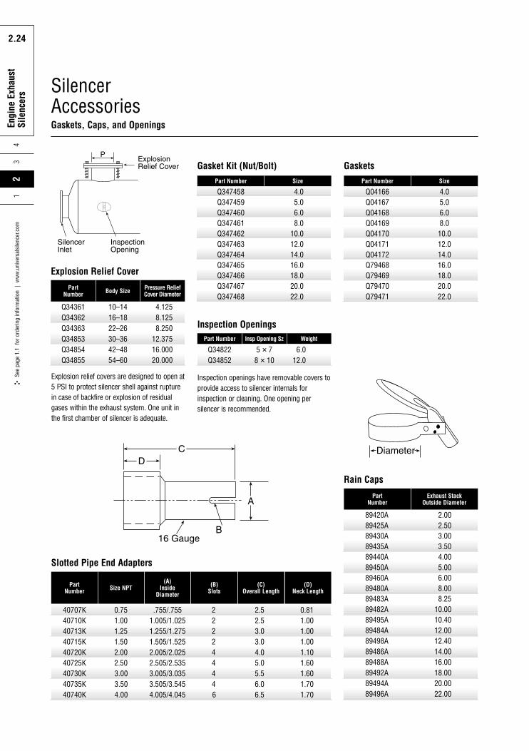
SilencerAccessoriesGaskets, Caps, and Openings
Q34361Q34362Q34363Q34853Q34854Q34855
10–1416–1822–2630–3642–4854–60
PartNumber Body Size
4.1258.1258.250
12.37516.00020.000
Pressure ReliefCover Diameter
Explosion Relief Cover
Explosion relief covers are designed to open at5 PSI to protect silencer shell against rupturein case of backfire or explosion of residualgases within the exhaust system. One unit inthe first chamber of silencer is adequate.
Inspection openings have removable covers toprovide access to silencer internals forinspection or cleaning. One opening persilencer is recommended.
Q34822Q34852
5 � 78 � 10
Part Number Insp Opening Sz
6.012.0
Weight
Inspection Openings
Q04166Q04167Q04168Q04169Q04170Q04171Q04172Q79468Q79469Q79470Q79471
4.05.06.08.010.012.014.016.018.020.022.0
Part Number Size
Gaskets
Q347458Q347459Q347460Q347461Q347462Q347463Q347464Q347465Q347466Q347467Q347468
4.05.06.08.0
10.012.014.016.018.020.022.0
Part Number Size
Gasket Kit (Nut/Bolt)
40707K40710K40713K40715K40720K40725K40730K40735K40740K
3.003.504.00
3.005/3.0353.505/3.5454.005/4.045
446
5.56.06.5
1.601.701.70
0.751.001.251.502.002.50
.755/.7551.005/1.0251.255/1.2751.505/1.5252.005/2.0252.505/2.535
222244
2.52.53.03.04.05.0
PartNumber Size NPT
(A) Inside
Diameter
(B)Slots
(C)Overall Length
0.811.001.001.001.101.60
(D)Neck Length
Slotted Pipe End Adapters
89420A89425A89430A89435A89440A89450A89460A89480A89483A89482A89495A89484A89498A89486A89488A89492A89494A89496A
2.002.503.003.504.005.006.008.008.25
10.0010.4012.0012.4014.0016.0018.0020.0022.00
PartNumber
Exhaust StackOutside Diameter
Rain Caps
Rota
ry P
ositi
ve
Blow
er S
ilenc
ers
2.25
Engi
ne E
xhau
stSi
lenc
ers
24
3
2.25
See
page
1.1
for
ord
erin
g in
form
atio
n |
ww
w.u
nive
rsal
sile
ncer
.com
1
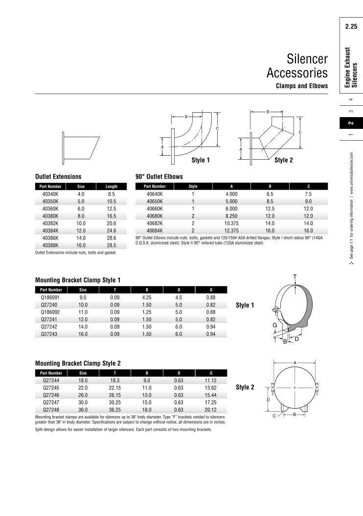
SilencerAccessories
Clamps and ElbowsExha
ust S
ilenc
ers
40340K40350K40360K40380K40382K40384K40386K40388K
4.05.06.08.010.012.014.016.0
Part Number Size
8.510.512.516.520.624.628.628.5
Length
Outlet Extensions
40640K40650K40660K40680K40682K40684K
111222
4.0005.0006.0008.25010.37512.375
6.58.512.512.014.016.0
7.59.012.012.014.016.0
Part Number Style A B C
90° Outlet Elbows
Q186091Q27240Q186092Q27241Q27242Q27243
9.010.011.012.014.016.0
0.090.090.090.090.090.09
4.251.501.251.501.501.50
4.55.05.05.06.06.0
Part Number Size T B D
0.880.820.880.820.940.94
G
Mounting Bracket Clamp Style 1
Q27244Q27245Q27246Q27247Q27248
18.022.026.030.036.0
18.322.1526.1530.2536.25
9.011.013.015.018.0
0.630.630.630.630.63
11.1213.6215.4417.2520.12
Part Number Size T B D G
Mounting Bracket Clamp Style 2
Mounting bracket clamps are available for silencers up to 36" body diameter. Type “F” brackets welded to silencersgreater than 36" in body diameter. Specifications are subject to change without notice, all dimensions are in inches.
Split design allows for easier installation of larger silencers. Each part consists of two mounting brackets.
90° Outlet Elbows include nuts, bolts, gaskets and 125/150# ASA drilled flanges; Style I short radius 90° (14GAD.Q.S.K. aluminized steel); Style II 90° mitered tube (12GA aluminized steel)
Outlet Extensions include nuts, bolts and gasket.
Style 1
Style 2
Style 1 Style 2
Rota
ry P
ositi
ve
Blow
er S
ilenc
ers
2.26
Engi
ne E
xhau
stSi
lenc
ers
43
2.26
See
page
1.1
for
ord
erin
g in
form
atio
n |
ww
w.u
nive
rsal
sile
ncer
.com
21
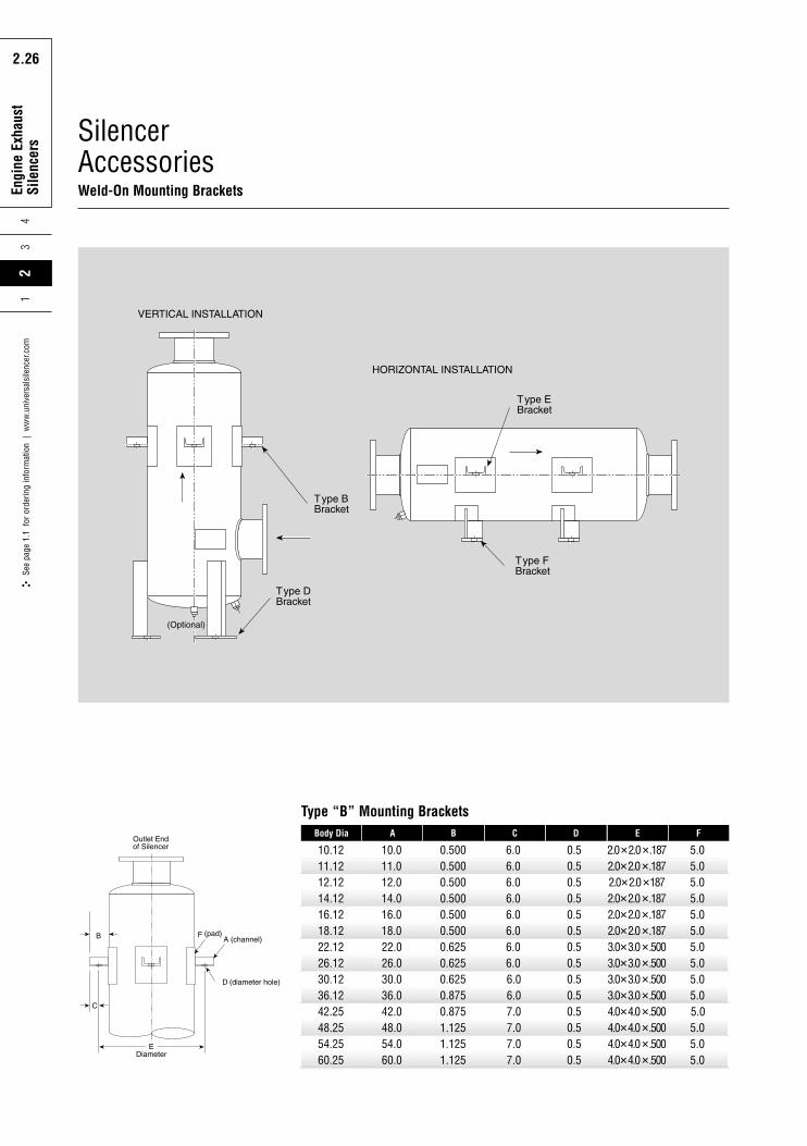
SilencerAccessoriesWeld-On Mounting Brackets Ex
haus
t Sile
ncer
s
10.1211.1212.1214.1216.1218.1222.1226.1230.1236.1242.2548.2554.2560.25
22.026.030.036.042.048.054.060.0
0.6250.6250.6250.8750.8751.1251.1251.125
6.06.06.06.07.07.07.07.0
0.50.50.50.50.50.50.50.5
3.0�3.0�.5003.0�3.0�.5003.0�3.0�.5003.0�3.0�.5004.0�4.0�.5004.0�4.0�.5004.0�4.0�.5004.0�4.0�.500
5.05.05.05.05.05.05.05.0
10.011.012.014.016.018.0
0.5000.5000.5000.5000.5000.500
6.06.06.06.06.06.0
0.50.50.50.50.50.5
Body Dia A B C D
2.0�2.0�.1872.0�2.0�.1872.0�2.0�1872.0�2.0�.1872.0�2.0�.1872.0�2.0�.187
5.05.05.05.05.05.0
E F
Type “B” Mounting Brackets
Rota
ry P
ositi
ve
Blow
er S
ilenc
ers
2.27
Engi
ne E
xhau
stSi
lenc
ers
24
3
2.27
See
page
1.1
for
ord
erin
g in
form
atio
n |
ww
w.u
nive
rsal
sile
ncer
.com
1
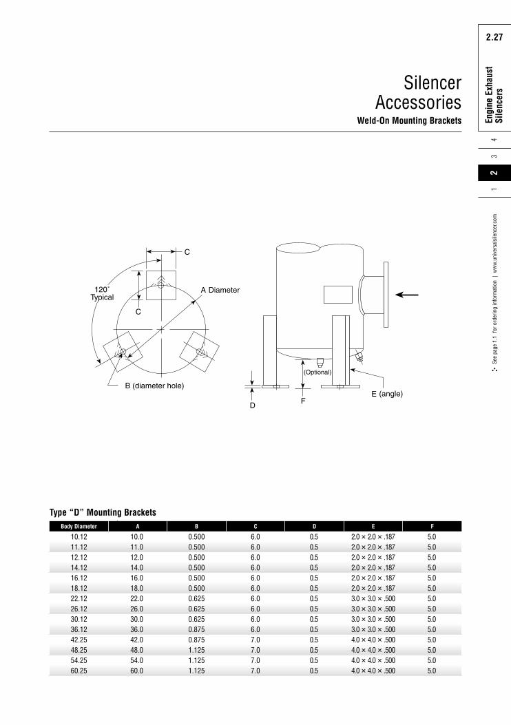
SilencerAccessories
Weld-On Mounting BracketsExha
ust S
ilenc
ers
10.1211.1212.1214.1216.1218.1222.1226.1230.1236.1242.2548.2554.2560.25
Body Diameter
Type “D” Mounting Brackets
10.011.012.014.016.018.022.026.030.036.042.048.054.060.0
A
0.5000.5000.5000.5000.5000.5000.6250.6250.6250.8750.8751.1251.1251.125
B
6.06.06.06.06.06.06.06.06.06.07.07.07.07.0
C
0.50.50.50.50.50.50.50.50.50.50.50.50.50.5
D
2.0 � 2.0 � .1872.0 � 2.0 � .1872.0 � 2.0 � .1872.0 � 2.0 � .1872.0 � 2.0 � .1872.0 � 2.0 � .1873.0 � 3.0 � .5003.0 � 3.0 � .5003.0 � 3.0 � .5003.0 � 3.0 � .5004.0 � 4.0 � .5004.0 � 4.0 � .5004.0 � 4.0 � .5004.0 � 4.0 � .500
E
5.05.05.05.05.05.05.05.05.05.05.05.05.05.0
F
Rota
ry P
ositi
ve
Blow
er S
ilenc
ers
2.28
Engi
ne E
xhau
stSi
lenc
ers
43
2.28
See
page
1.1
for
ord
erin
g in
form
atio
n |
ww
w.u
nive
rsal
sile
ncer
.com
21
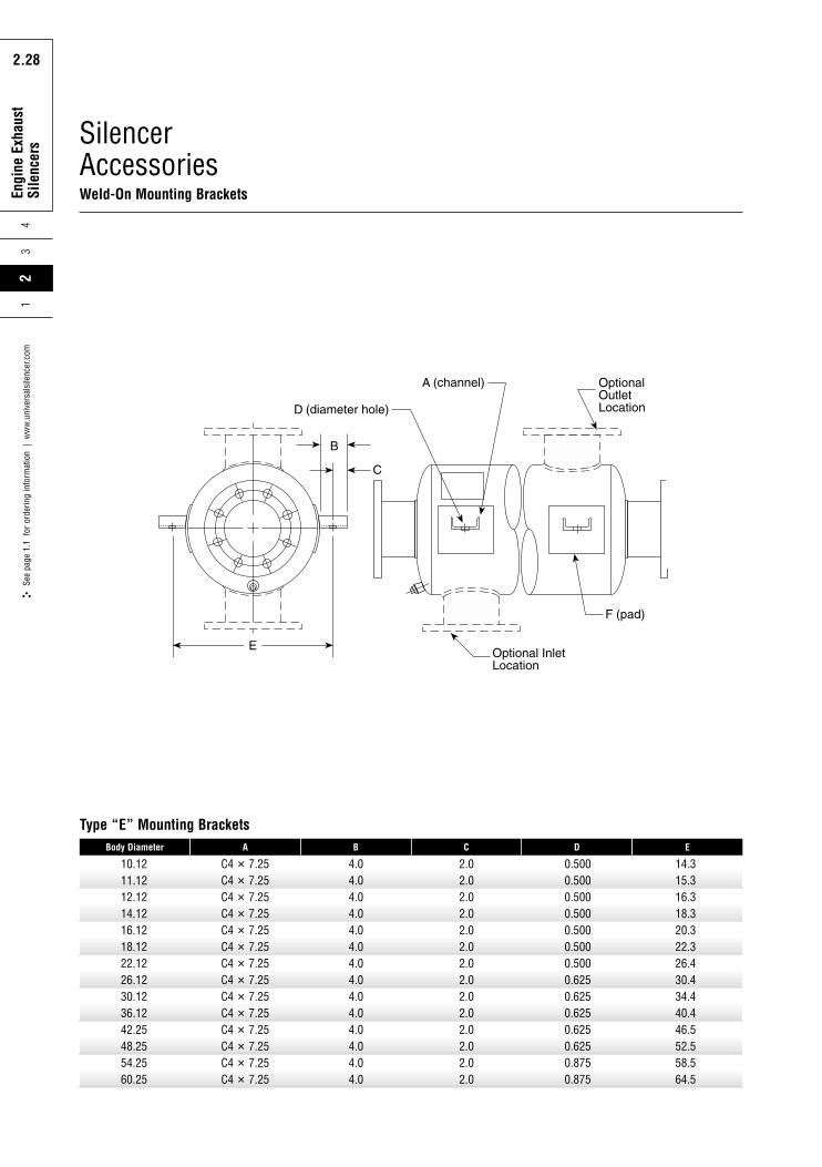
SilencerAccessoriesWeld-On Mounting Brackets Ex
haus
t Sile
ncer
s
10.1211.1212.1214.1216.1218.1222.1226.1230.1236.1242.2548.2554.2560.25
Body Diameter
Type “E” Mounting Brackets
C4 � 7.25C4 � 7.25C4 � 7.25C4 � 7.25C4 � 7.25C4 � 7.25C4 � 7.25C4 � 7.25C4 � 7.25C4 � 7.25C4 � 7.25C4 � 7.25C4 � 7.25C4 � 7.25
A
4.04.04.04.04.04.04.04.04.04.04.04.04.04.0
B
2.02.02.02.02.02.02.02.02.02.02.02.02.02.0
C
0.5000.5000.5000.5000.5000.5000.5000.6250.6250.6250.6250.6250.8750.875
D
14.315.316.318.320.322.326.430.434.440.446.552.558.564.5
E
Rota
ry P
ositi
ve
Blow
er S
ilenc
ers
2.29
Engi
ne E
xhau
stSi
lenc
ers
24
3
2.29
See
page
1.1
for
ord
erin
g in
form
atio
n |
ww
w.u
nive
rsal
sile
ncer
.com
1
SilencerAccessories
Weld-On Mounting Brackets
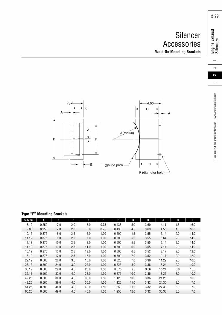
8.129.00
10.1211.1212.1214.1216.1218.1222.1226.1230.1236.1242.2548.2554.2560.25
0.3750.3750.5000.5000.5000.5000.5000.5000.5000.500
15.017.020.024.029.032.034.039.044.049.0
2.52.53.03.04.04.04.04.04.04.0
13.015.018.022.026.028.030.035.040.045.0
1.001.001.001.001.501.501.501.501.501.50
0.5000.5000.6250.6250.8750.8751.1251.1251.2501.250
0.2500.2500.3750.3750.3750.375
7.07.08.09.0
10.013.0
2.02.02.52.52.52.5
5.05.06.07.08.0
11.0
Body Dia. A B C D
0.750.751.001.001.001.00
0.4380.4380.5000.5000.5000.500
E F
6.57.07.08.09.0
10.010.011.011.012.0
5.04.51.55.05.56.0
G
3.523.523.363.363.363.363.363.323.323.32
3.693.693.553.553.553.55
H
8.179.17
11.2213.2415.2418.2621.2624.3027.3330.33
4.114.555.145.646.147.14
J
2.02.02.02.03.03.03.03.03.03.0
1.51.52.02.02.02.0
K
12.012.010.010.010.010.010.07.07.07.0
16.016.014.014.014.014.0
L
Type “F” Mounting Brackets
Rota
ry P
ositi
ve
Blow
er S
ilenc
ers
2.30
Engi
ne E
xhau
stSi
lenc
ers
43
2.30
See
page
1.1
for
ord
erin
g in
form
atio
n |
ww
w.u
nive
rsal
sile
ncer
.com
21
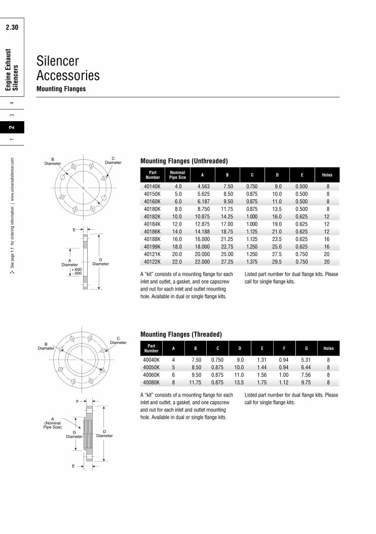
SilencerAccessoriesMounting Flanges
40140K40150K40160K40180K40182K40184K40186K40188K40199K40121K40122K
14.016.018.020.022.0
14.18816.00018.00020.00022.000
18.7521.2522.7525.0027.25
1.1251.1251.2501.2501.375
21.023.525.027.529.5
0.6250.6250.6250.7500.750
4.05.06.08.0
10.012.0
4.5635.6256.1878.750
10.87512.875
7.508.509.50
11.7514.2517.00
0.7500.8750.8750.8751.0001.000
PartNumber
NominalPipe Size A B C
9.010.011.013.516.019.0
0.5000.5000.5000.5000.6250.625
D E
1216162020
8888
1212
Holes
Mounting Flanges (Unthreaded)
Listed part number for dual flange kits. Pleasecall for single flange kits.
40040K40050K40060K40080K
4568
7.508.509.50
11.75
0.7500.8750.8750.875
9.010.011.013.5
PartNumber A B C D
1.311.441.561.75
0.940.941.001.12
E F
5.316.447.569.75
G
8888
Holes
Mounting Flanges (Threaded)
Listed part number for dual flange kits. Pleasecall for single flange kits.
A “kit” consists of a mounting flange for eachinlet and outlet, a gasket, and one capscrewand nut for each inlet and outlet mountinghole. Available in dual or single flange kits.
A “kit” consists of a mounting flange for eachinlet and outlet, a gasket, and one capscrewand nut for each inlet and outlet mountinghole. Available in dual or single flange kits.
Rota
ry P
ositi
ve
Blow
er S
ilenc
ers
3.1
Emis
sion
s So
lutio
ns
3.1
34
See
page
1.1
for
ord
erin
g in
form
atio
n |
ww
w.u
nive
rsal
sile
ncer
.com
12
EmissionsSolutions
Combination Silencer/CatalystThe combination silencer/catalyst is a uniquevariation of a standard heavy-duty engineexhaust silencer, extended slightly to allowroom for catalyst insertion. This newsolution utilizes one of two catalystcapturing techniques within the silencershell. The first employs a gasket-wrappedcatalyst module, which fits tightly betweeninternal guide rails. The second uses atorturous path configuration, which usesserpentine interlocks around the catalyst toprevent gas bypass. Both designscompletely seal the silencer and ensure thatexhaust gas passes through the catalyst. For the greatest emissions reduction results,special care is given to enable exhaust gasuniformity prior to passing through thecatalyst. The combination silencer/catalystsolutions are available in four performancegrades, with overall attenuation to 40 dB.
pass tubes
catalyst
Catalyst Housing PackagesBase catalyst housing packages are largeend-in, end-out configured units with aflanged inlet and outlet connection. Conicalsections (top right) or standard dishedsilencer heads are used, depending on thepressure drop requirements of the unit. Thecylindrical housing body can incorporateeither of the catalyst capturing designs asthe combination silencer/catalyst units. Thiscomplete catalyst package includes multiplepressure, temperature and other measuringports, and is available in various stainlesssteels or standard carbon steel.
Available emissions solutions includethe following:
soot filters
diesel oxidation catalysts
catalyst housings
combination silencer/catalyst
custom applications
silencer/catalyst
conical catalyst housingconical catalyst housing
upright catalyst housingupright catalyst housing
silencer/catalyst
Engineered SolutionsNelson designs and validates both standardand custom noise control and air filtrationsolutions to meet the most challengingcustomer requirements. Nelson’sattenuation and filtration system design anddevelopment is supported by in-houseacoustic, filtration, emission and dynamictesting laboratories. These in-housetechnical centers, coupled with thecompany’s more than 65 years of designand manufacturing experience, enableNelson to engineer efficient and effectivesolutions for all applications—from themost basic to the most complex.
Nelson challenges any noise controlengineer to match its wide and variedselection of intake and exhaust productsand services. Nelson makes this solutionsportfolio available through the use of itsextensive in-house acoustic expertise andadvanced engineering technologies. Theresulting products are an unparalleled lineof standard and custom-designed silencers,spark arresters, filter housings, elements,connectors, tube assemblies, catalystdesigns, or any combination desired. Eachproduct includes a complete range ofoptions and accessories, such as specialmaterials, insulation, custom inlet and outletconnections and multiple mounting options.Nelson’s solutions are more than just afabricated stand-alone product; they areintegrated components of a complete noisecontrol solution, from intake to exhaust.
Nelson’s noise control and air filtrationsolutions are used in many differentindustries, including industrial process,power generation, oil and gas, marineand emissions.
Why are in-house capabilities important toNelson customers? Simply consider thebenefits Nelson boasts over a fabricator:
TechnicalCapabilities
4Se
e pa
ge 1
.1 f
or o
rder
ing
info
rmat
ion
| w
ww
.uni
vers
alsi
lenc
er.c
om1
23
Rota
ry P
ositi
ve
Blow
er S
ilenc
ers
4.1
Tech
nica
lCa
pabi
litie
s
4.1
A complete range of sizes, materials
and configurations
Standard and custom designs
Complete in-house acoustic, filtration
and emissions testing facilities
Acoustic site surveys and analysis
More than 65 years of design and
manufacturing experience
Fast response to customer needs
Full after-sales engineering support
Technical CenterThe Nelson Technical Center contains acomplete acoustic laboratory whereperformance testing on engine, blower andfan silencers can be carried out. Theacoustic lab consists of a sound analysisroom, two semi-anechoic chambers andmultiple testing cells. Key measurements,such as sound level, exhaust restriction,temperature, horsepower and fuelconsumption can be performedsimultaneously in these cells. All phases oftesting are computer controlled, includingequipment operation, data acquisition andstorage, frequency analysis and reportgeneration. This acoustic lab enables Nelsonengineers to optimize all aspects of productperformance before it is put into the field.
Prototype DevelopmentThe Prototype Development Department(PDD) engineers and produces silencer andfilter samples for testing and development.The PDD works closely with the EquipmentDevelopment Department (EDD) to buildtest equipment used in all the technicalcenters. Nelson’s Quality Assurance teaminspects all parts before and after assemblyto ensure optimal performance andcustomer satisfaction.
Dynamic TestingThe Dynamics Laboratory houses facilitiesfor exhaust product structural andvibration testing. This allows Nelson toscrutinize the structural integrity of exhaustsystems through the simulation of actualoperating conditions. By directing engineexhaust gases through a product duringvibration testing, Nelson engineers are ableto operate within a continuousimprovement environment.
Material TestingEnvironmental, physical and chemicaltesting is performed in the MaterialEvaluation and Analytical Laboratories(MEAL). Protective coating and corrosionresistance performance are assessedthrough methods such as salt spray tests.
Engineering ServicesAgain, look to Nelson for these technical needs:
Site acoustic surveys
Standard and custom acoustic design
Specification support and preparation
Structural design
System inspection
Field dimension verification
Complete project management
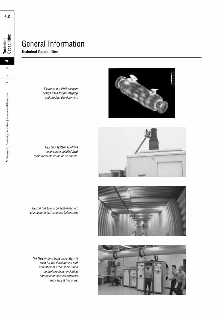
Rota
ry P
ositi
ve
Blow
er S
ilenc
ers
4.2
Tech
nica
lCa
pabi
litie
s
4.2
See
page
1.1
for
ord
erin
g in
form
atio
n |
ww
w.u
nive
rsal
sile
ncer
.com
41
23
General InformationTechnical Capabilities
Nelson’s system solutionsincorporate detailed field
measurements at the noise source.
Nelson has two large semi-anechoicchambers in its Acoustics Laboratory.
Example of a ProE silencerdesign used for prototyping
and product development.
The Nelson Emissions Laboratory isused for the development and
evaluation of exhaust emissioncontrol products, including
combination silencer/catalystsand catalyst housings.
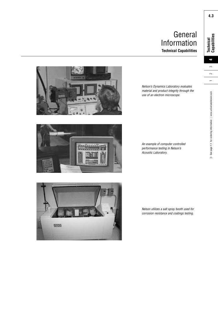
Rota
ry P
ositi
ve
Blow
er S
ilenc
ers
4.3
Tech
nica
lCa
pabi
litie
s
4.3
4Se
e pa
ge 1
.1 f
or o
rder
ing
info
rmat
ion
| w
ww
.uni
vers
alsi
lenc
er.c
om1
23
GeneralInformationTechnical Capabilities
Nelson’s Dynamics Laboratory evaluatesmaterial and product integrity through theuse of an electron microscope.
An example of computer controlledperformance testing in Nelson’s Acoustic Laboratory.
Nelson utilizes a salt spray booth used forcorrosion resistance and coatings testing.

Your markets,our solutions
P.O. Box 411 | 1925 Highway 51/138Stoughton | Wisconsin 53589 USA888.300.4272 | Fax 608.873.4298
www.universalsilencer.com