Welcome to the course in Heat Transfer (MMV031) – L1 · students to focus on theory (lectures)...
57
Welcome to the course in Heat Transfer (MMV031) – L1 Martin Andersson & Zan Wu
Transcript of Welcome to the course in Heat Transfer (MMV031) – L1 · students to focus on theory (lectures)...

Welcome to the course in Heat Transfer (MMV031) – L1Martin Andersson & Zan Wu

Agenda
• Organisation
• Introduction to Heat Transfer
• Heat Exchangers (Ex 108)

Course improvement compared to last years
• 2016: The lectures and tutorial sessions are integrated, mainly because it is hard for most students to focus on theory (lectures) for 90 minutes.
• 2015: Exercises where students are expected to solve problems themselves or in small groups are added. Instead the amount of tutorial sessions (where the teacher solved problems) are decreased.
• 2014: 3 DLs for home assignments was implemented (instead of 1)

Contents of the course
• Heat Conduction• Convection• Thermal Radiation• Condensation• Evaporation, Boiling• Heat Exchangers

Organisation
• Lectures with tutorials• Guest lectures• Exercises
• Mandatory home assignments
• Exam (mandatory)

Organisation
• Examiner: Associate Professor Martin Andersson
• Teachers: Martin Andersson and Zan Wu (offices at 5th
floor M-building)
• Course administrator: Elna Andersson (office at 5th floor M-building)
Organisation
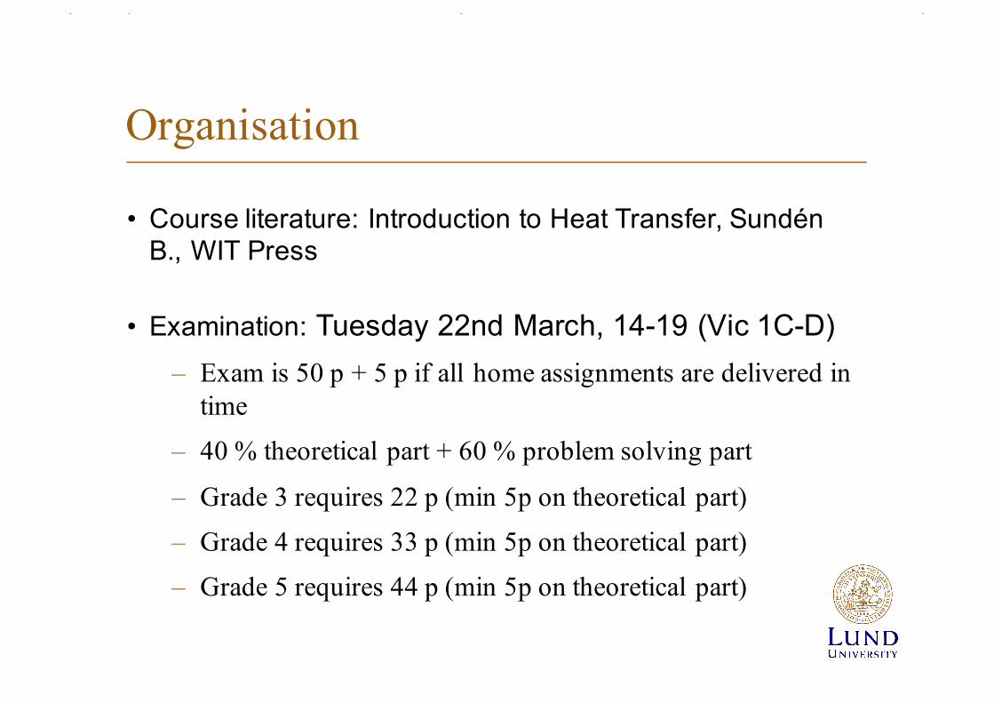
• Course literature: Introduction to Heat Transfer, SundénB., WIT Press
• Examination: Tuesday 22nd March, 14-19 (Vic 1C-D) – Exam is 50 p + 5 p if all home assignments are delivered in
time
– 40 % theoretical part + 60 % problem solving part
– Grade 3 requires 22 p (min 5p on theoretical part)
– Grade 4 requires 33 p (min 5p on theoretical part)
– Grade 5 requires 44 p (min 5p on theoretical part)

Guest lectures and Study Visit
• Alfa Laval (study visit)– World leading company in plate heat exchangers
• Guest lecture(s):– John Weisend, ESS
– Fredrik Nilsson, Heatex– Magnus Genrup, LTH (guru in turbines)
– Mats Annerfeldt, Siemens (date not confirmed)

Introduction
• Heat is energy passing a system boundary due to a temperature difference
• Heat is a form of energy in transition.
• Heat conduction• Heat convection (natural (no pump, fan etc) or forced)• Thermal radiation

Introduction

Introduction

Heat conduction
T1T2
T1 > T2
qThickness b
λ
q = λ(T1-T2)/b

Heat conduction

Solids Carbon Steel λ = 15- 50 W/mK
Polymers, λ = 0.1-0.5 W/mK
Liquids
Water λ = 0.6 W/mK
Oil λ = 0.15 W/mK
Gases
Air λ = 0.025 W/mK
H2 (hydrogen) λ = 0.2 W/mK
Thermal conductivity (examples)

Convection
q = α(TS-T∞) = h(TS-T∞)
Tsq
U∞ T∞ Ts > T∞

How to determine α or h
• Depends on: – Flow velociy– Fluid (gas or liquid)– Geometry – sometimes on temperature– Forced convection, Natural convection, Mixed convection
• Nu = αL/λf = function (Re=UL/ν, Pr=µcp/λf , geometry) or• Nu = αL/λf = function (Gr=gβΔΤL3/ν2, Pr=µcp/λf , geometry) or• Nu = αL/λf = function (Re, Gr, Pr, geometry)

Thermal Radiation
Qnet = A1F12εeff (T14-T2
4)
q1
q2 T2
T1


Introduction to heat exchangers (ch 15)

What is a Heat Exchanger?
A heat exchanger is a device that is used to transfer thermal energy (enthalpy) between two or more fluids, between a solid surface and a fluid,
or between solid particulates and a fluid,at different temperaturesand in thermal contact.

Classification of heat exchangers

• Transfer process• Number of fluids• Degree of surface contact• Design features• Flow arrangements • Heat transfer mechanisms
Classification of heat exchangers

Fig. 1 Heat transfer surface area density spectrum ofexchanger surfaces ( Shah, 1981).
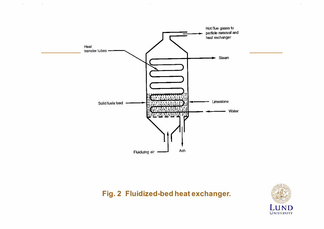
Fig. 2 Fluidized-bed heat exchanger.

Fig. 3 (a) Shell-and- tube exchanger with one shell passand one tube pass;
(b) shell-and- tube exchanger with one shell pass and two tube passes.

Fig. 4 Standard shell types and front- andrear-end head types (From TEMA, 1999).

Fig. 5 Gasketed plate-and-frame heat exchanger.

Fig. 6 Plates showing gaskets around the ports (Shah and Focke, 1988).

Fig. 7 Section of a welded plate heat exchanger.

Fig. 9 Spiral plate heat exchanger with both fluids in spiral counter flow.

Fig. 10 (a) Lamella heat exchanger;(b) cross section of a lamella heat exchanger,(c) lamellas

Fig. 11 Printed-circuit cross flow exchanger
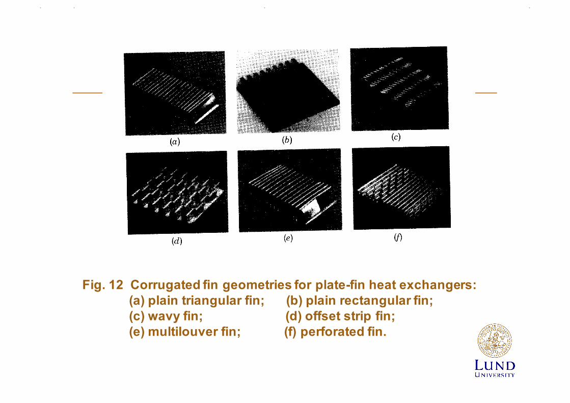
Fig. 12 Corrugated fin geometries for plate-fin heat exchangers:(a) plain triangular fin; (b) plain rectangular fin; (c) wavy fin; (d) offset strip fin; (e) multilouver fin; (f) perforated fin.

Fig. 13 (a) Individually finned tubes;(b) flat (continuous) fins on an array of tubes.

Fig. 14 Individually fin tubes.

Fig. 15 Heat wheel or a rotary regenerator madefrom a polyester film.

Classification according to transfer process
Indirect contact type Direct contact type
Direct transfer Storage Fluidized bed Immiscible fluids
Gas-liquid Liquid-vapour
Single-phase Multiphase
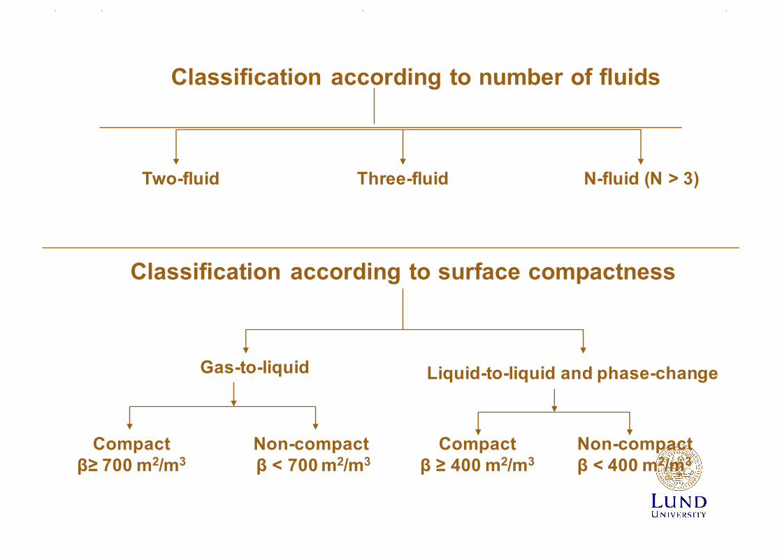
Classification according to number of fluids
Two-fluid Three-fluid N-fluid (N > 3)
Classification according to surface compactness
Gas-to-liquid Liquid-to-liquid and phase-change
Compactβ≥ 700 m2/m3
Non-compactβ < 700 m2/m3
Compactβ ≥ 400 m2/m3
Non-compactβ < 400 m2/m3

Classification according to design or type
Tubular Plate-type Extended surface Regenerative
PHE Spiral Plate coil Printed circuit
Gasketed Welded Brazed
Double-pipe Shell-and-tube Spiral tube Pipe coils
Cross-flow to tubes
Parallel flowto tubes
Plate-fin Tube-fin
Ordinary Separatingwall
Heat-pipewall
Rotary Fixed-matrix Rotatinghoods

Classification according to flow arrangements
Single-pass Multipass
Counter flow Parallel flow Cross flow Split flow Divided flow
Extended surface
Cross-Counter flow
Cross-parallel flow
Compound flow
Shell-and-tube Plate
Parallel counter flowm-shell passesn-tube passes
split-flow Divided-flow
Fluid 1 m passesFluid 2 n passes

Classification according to heat transfer mechanisms
Single-phase convection on both sides
Single-phase convection on one side, Two-phase convection on other side
Two-phase convection on both sides
Combined convection and radiative heat transfer

Classification according to process function
Condensers Liquid-to-vaporphase-changeexchangers
Heaters Coolers Chillers

Convective heat transfer
vägg
Fluid1
Fluid2

Overall heat transfer coefficient
mm1 tTR
tUAQ Δ⋅=Δ⋅=!

Expression for overall thermal resistance
oóoFvlw
w
iiFii
1111
oAAA
bAA
TRα
+α
+λ
+α
+α
=

Values of the heat transfer coefficient W/m2K
• Air atmospheric pressure 5-75• Air pressurized 100 - 400• Water, liquid 500-20 000• Organic liquids 50 000• Boiling 2 500 -100 000• Condensation 3 000-100 000

Correlations for the heat transfer coefficient
• Nu = hL/k = function (flow velocity, physical properties, geometry) = function (Re, Pr, geometry)

General research needs
• How to achieve more compact heat exchangers• High thermal efficiency
• Balance between enhanced heat transfer and accompanied pressure drop
• Material issues especially for high temperature applications• Manufacturing methodology
• Fouling
• Non-steady operation
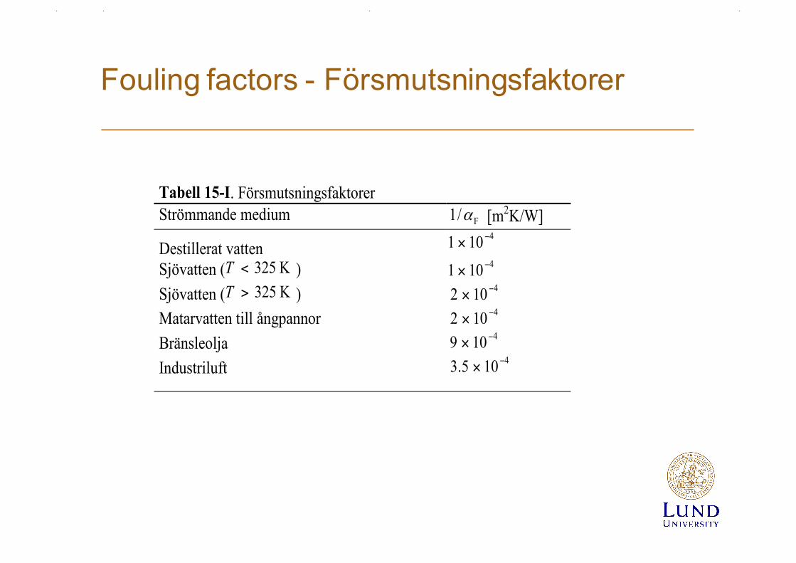
Fouling factors - Försmutsningsfaktorer
Tabell 15-I. FörsmutsningsfaktorerStrömmande medium F/1 α [m2K/W]
Destillerat vatten4101 −×
Sjövatten ( K 325<T ) 4101 −×
Sjövatten ( K 325>T ) 4102 −×
Matarvatten till ångpannor 4102 −×
Bränsleolja 4109 −×
Industriluft 4105.3 −×
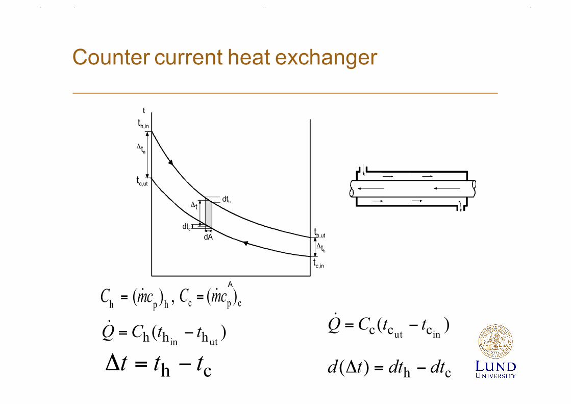
Counter current heat exchanger
t
A
dth
dtcdA
Δt
th,in
tc,ut
th,ut
tc,in
Δtb
Δta
)(utin hhh ttCQ −=! )(
inut ccc ttCQ −=!
ch ttt −=Δ ch)( dtdttd −=Δ
hph )( cmC != , cpc )( cmC !=

Counter current Hex
⎟⎟⎠
⎞⎜⎜⎝
⎛−⋅=Δ
hc
11)(CC
Qdtd !
⎟⎟⎠
⎞⎜⎜⎝
⎛−Δ=Δ
hc
11)(CC
tdAUtd
⎟⎟⎠
⎞⎜⎜⎝
⎛−=
Δ
Δ
hc
11)(CC
dAUttd
ccphhp )()( dtcmdtcmtdAUQd !!! −=−=Δ⋅=

Counter current Hex
∫∫ ⎟⎟⎠
⎞⎜⎜⎝
⎛−=
ΔΔ
Δ
Δ
A
CCdAU
ttd
0 hc
t
t
11)(b
a
⎟⎟⎠
⎞⎜⎜⎝
⎛−=
ΔΔ
hca
b 11lnCC
UAtt
⎟⎟⎠
⎞⎜⎜⎝
⎛ −−
−
Δ=
Δ
Δ
Q
tt
Q
tt
tQ
tt
!!! )()(
ln utininut hhcc
ma
b
a
b
abm
lntttt
LMTDt
Δ
ΔΔ−Δ
==Δ
)(
)(ln
)()(
utin
inut
utininut
ch
ch
chchm
tt
tttttt
LMTDt
−
−
−−−==Δ

Expression for overall thermal resistance

Parallel flow Hex,Co-Current Hex
)(
)(ln
)()(
utut
inin
ututinin
ch
ch
chchm
tt
tttttt
t
−
−
−−−=Δ
a
b
abm
lntttt
t
Δ
ΔΔ−Δ
=Δ
t
A
dth
dtcdA
Δt
th,in
tc,in
th,ut
tc,ut
ΔtbΔta

Arbitrary Hex
LMTDFUAQ ⋅⋅=!
F korrektionsfaktor som beror av två parametrar P och R;
F correction factor depending on two parameters P and R
inin
inut
ch
cc
tt
ttP
−
−=
hp
cp
)(
)(
cm
cmR
!
!=
R kan också skrivas; R can also be written
inut
utin
cc
hh
tt
ttR
−
−=

F vs P och/and R; Shell-and-tube heat exchanger; one shell pass, two tube passes
0 0.1 0.2 0.3 0.4 0.5 0.6 0.7 0.8 0.9 10.5
0.6
0.7
0.8
0.9
1.0
P
Korre
ktio
nsfa
ktor
, F
R =
6.0
4.0
3.0
2.0 1.5
1.0
0.8
0.6
0.4
0.2
0.1
tc,in
tc,ut
th,ut
th,in
inin
inut
ch
cc
tt
ttP
−
−=
inut
utin
cc
hh
tt
ttR
−
−=