Welcome to Solid Edge University 2015 - Siemens PLM...
59
Restricted © Siemens AG 2015 Realize innovation. Welcome to Solid Edge University 2015 Siemens PLM Software #SEU15
Transcript of Welcome to Solid Edge University 2015 - Siemens PLM...

Restricted © Siemens AG 2015 Realize innovation.
Welcome to Solid Edge University 2015Siemens PLM Software
#SEU15

Restricted © Siemens AG 2015
2015-10-27Page 2 Siemens PLM Software
• What are some new modeling tools in ST8 that will help
me do my job faster and easier?
• Tools and techniques in the Ordered environment you
may have never considered using.
Part Modeling: A Hands-on Experience

Restricted © Siemens AG 2015
2015-10-27Page 3 Siemens PLM Software
New Modeling Tools in Solid Edge ST8
• Pattern by Table
• Can be used for replicating features in a Synchronous or Ordered part
that does not conform to a rectangular or circular pattern.
• Can be used to drive patterns of features in mating parts that can
be linked to the same spreadsheet for their pattern locations.

Restricted © Siemens AG 2015
2015-10-27Page 4 Siemens PLM Software
Pattern by Table
• The Pattern Table (Microsoft Excel spreadsheet):
• The columns of the table are used for
location and orientation
• Column A = +/- Coordinate along the “X” axis
• Column B = +/- Coordinate along the “Y” axis
• Column C = +/- Angle relative to the parent instance
• +/- “X” and +/- “Y” Axis directions are set by selecting a predefined
coordinate system as part of the patterning steps
• Row 1 is always the coordinates for
the feature/features to the pattern.
• Spreadsheet Restrictions:
• No Header/Title row for columns
is permitted.
• Only columns A, B and C
may contain +/- numeric values.

Restricted © Siemens AG 2015
2015-10-27Page 5 Siemens PLM Software
Pattern by Table
• Open CONTROLLER.asm from the 01-Controller folder.
• Change the configuration to 02-All to see the button pad.
• The layout of the buttons in the button pad are already linked to
a Pattern by Table driving spreadsheet.

Restricted © Siemens AG 2015
2015-10-27Page 6 Siemens PLM Software
Pattern by Table
• Select the BODY-FRONT part to edit in place.
• Note the slot for the first button in the upper left.
• This will be the slot we will use as the parent to
pattern the remaining button slots using a spreadsheet.
• Open BUTTON_LOCATIONS.xlsx from the Controller folder
• Remember the first row is the “X” & “Y” locations of the
parent instance.
• HINT: A value of 0,0,0 indicates the rest of the
coordinates are being measured from the
parent instance.
Restricted © Siemens AG 2015
2015-10-27Page 7 Siemens PLM Software
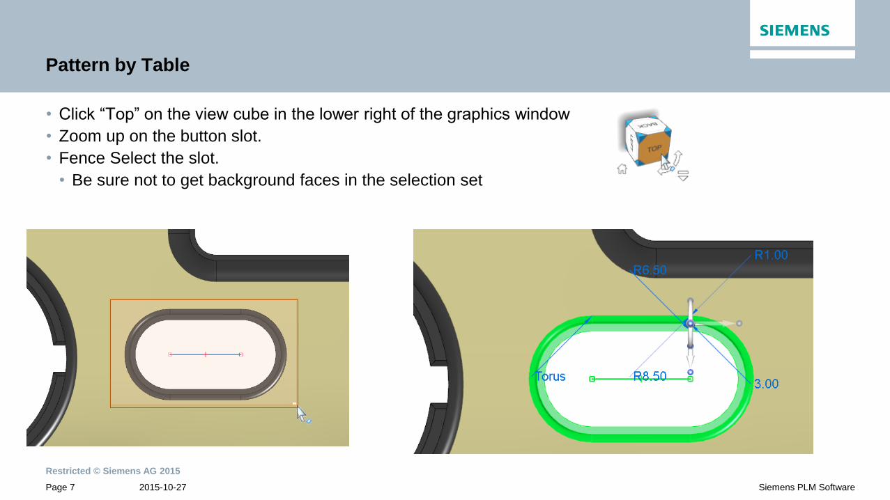
Pattern by Table
• Click “Top” on the view cube in the lower right of the graphics window
• Zoom up on the button slot.
• Fence Select the slot.
• Be sure not to get background faces in the selection set

Restricted © Siemens AG 2015
2015-10-27Page 8 Siemens PLM Software
Pattern by Table
• On the drop-down menu for Pattern, select the Pattern by Table command.
• The first step is to identify the coordinate system that will determine
the +/- “X” and “Y” directions.
• Select the Base coordinate system

Restricted © Siemens AG 2015
2015-10-27Page 9 Siemens PLM Software
Pattern by Table
• In the Instance Table, Browse to the BUTTON_LOCATIONS.xlsx

Restricted © Siemens AG 2015
2015-10-27Page 10 Siemens PLM Software
Pattern by Table
• In the Instance Table, change the Reference Point option to Selected Keypoint.
• In this example, the locations specified in the spreadsheet are originated from the center of the slot
feature that we are patterning.
• Remember the feature to pattern location is the first row in the spreadsheet.
• If the locations were measured from the coordinate system, the first row “x, y” locations would contain
non-zero values

Restricted © Siemens AG 2015
2015-10-27Page 11 Siemens PLM Software
Pattern by Table
• In the QuickBar, change the keypoint option to locate Midpoints.
• Select the midpoint of the centerline sketch for the slot
feature we are patterning.
• Note the pattern preview update.
• Click the green checkmark to accept the pattern

Restricted © Siemens AG 2015
2015-10-27Page 12 Siemens PLM Software
Pattern by Table
• Hide all sketches and coordinate systems from the Right Mouse Button context menu.
• Now let’s make a change to the button locations via the
spreadsheet locations and orientations.
• Note the colored rows in the spreadsheet correlate to the columns
of buttons in our model.
• This is not required and is simply
being used to help us visualize
our goals.

Restricted © Siemens AG 2015
2015-10-27Page 13 Siemens PLM Software
Pattern by Table
• We want to first eliminate the center 2 rows of slots in each column.
• Select the middle instances in each column in the spreadsheet
• Press the CTL key while selecting each row to add to the select set to delete.
• Rows 2, 3, 6, 7, 10, 11, 14 and 15
• Right Mouse click and select Delete

Restricted © Siemens AG 2015
2015-10-27Page 14 Siemens PLM Software
Pattern by Table
• After deleting the rows, Save the spreadsheet.
• Mouse over the Solid Edge graphics window and the pattern will update automatically

Restricted © Siemens AG 2015
2015-10-27Page 15 Siemens PLM Software
Pattern by Table
• Next we want to centralize the middle columns of buttons to form a circular looking pattern.
• We need to move the top two buttons down (11.00 mm) and rotate them to the opposite direction of their
current rotation.
• Edit columns B (“Y” value) and C (Rotation Angle) of rows 3 and 5
• We need to move the bottom 2 buttons straight up 11.00 mm.
• Edit column B (“Y” value) of rows 4 and 6

Restricted © Siemens AG 2015
2015-10-27Page 16 Siemens PLM Software
Pattern by Table
• Subtract 11.00 mm from cells 3B and 5B = -11
• Change the –20 to a +20 for cell 3C
• Change the +20 to a -20 for cell 5C
• Add 11.00 mm to cells 4B and 6B = -55
• SAVE the spreadsheet and mouse over
to the Solid Edge window to see the update

Restricted © Siemens AG 2015
2015-10-27Page 17 Siemens PLM Software
Pattern by Table
• Next we want to add a new horizontal button directly in the center of the pattern.
• This will be a new column in the pattern = a new row in the spreadsheet.
• Right Click on row 5 and click Insert to add a new row 5 to the spreadsheet.
• Highlight the 3 cells in the new row (5) and Right Click again and click Format Cells.
• Change the Background Color on the Fill tab to a shade of pink to differentiate it is a new column.
• Again, this is not required and is used just for clarity.

Restricted © Siemens AG 2015
2015-10-27Page 18 Siemens PLM Software
Pattern by Table
• To add a new button the middle we need to fill in the “X”, “Y”, and orientations fields.
• Cell 5A = (126/2) = 63 for “X” value
• Cell 5B = (-66/2) = -33 for “Y” value
• Cell 5C = same as the parent orientation = 0
• Save the spreadsheet and mouse over to the Solid Edge window to update the model

Restricted © Siemens AG 2015
2015-10-27Page 19 Siemens PLM Software
Pattern by Table
• Close and return back to the assembly.
• Notice the button pad is out of date to the spreadsheet changes.
• To update the changes in the BUTTON PAD, simply select the
part and click Edit In Place and it will update automatically.

Restricted © Siemens AG 2015
2015-10-27Page 20 Siemens PLM Software
Pattern by Table
• Close and return back to the assembly
to see the final design!

Restricted © Siemens AG 2015
2015-10-27Page 21 Siemens PLM Software
New Modeling Tools in Solid Edge ST8
• “Like Me” Pattern – Pattern Recognition
• Automatically recognizes patterns of selected geometry in a synchronous model.
• Perfect for editing geometry on an imported “dumb” model!

Restricted © Siemens AG 2015
2015-10-27Page 22 Siemens PLM Software
Pattern Recognition (synchronous only)
• Open DH2-00131_A.par from the 02-LikeMe folder.
• This is a real part from a customer who allowed us to
use this for demonstration.
• Notice this is an imported part and that there are no
features listed in the PathFinder.
• Also notice the holes in the center ring and slots are
spaced between the outer retainer arched features.

Restricted © Siemens AG 2015
2015-10-27Page 23 Siemens PLM Software
Pattern Recognition (synchronous only)
• First we want to recognize the cylinders as Hole features so we can modify them.
• Under Hole on the Home Tab, click Recognize Holes
• The center 52.00 mm diameter bore is recognized along with the
twelve 4.83 mm diameter holes.
• Placing your mouse over a row will highlight the corresponding
holes in the model.

Restricted © Siemens AG 2015
2015-10-27Page 24 Siemens PLM Software
Pattern Recognition (synchronous only)
• Let’s change the simple hole type of the 12 holes to tapped holes by clicking on the Hole Options icon.
• Set the standard to ISO Metric
• Change the type to Threaded
• Change the size from the list to M6 x 0.5
• Change depth to Finite Extent
• Set the hole depth to 20.00 mm
• V bottom angle
• Change the Thread extent option: To hole extent.

Restricted © Siemens AG 2015
2015-10-27Page 25 Siemens PLM Software
Pattern Recognition (synchronous only)
• Let’s rename the Holes to:
• M6 Threaded Holes
• Center Bore
• Click OK to dismiss the
Hole Options and
Hole Recognition dialogs
• Now there is a list of 12
individual threaded holes.
Restricted © Siemens AG 2015
2015-10-27Page 26 Siemens PLM Software
Pattern Recognition (synchronous only)
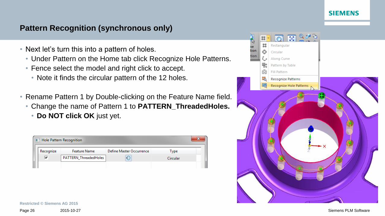
• Next let’s turn this into a pattern of holes.
• Under Pattern on the Home tab click Recognize Hole Patterns.
• Fence select the model and right click to accept.
• Note it finds the circular pattern of the 12 holes.
• Rename Pattern 1 by Double-clicking on the Feature Name field.
• Change the name of Pattern 1 to PATTERN_ThreadedHoles.
• Do NOT click OK just yet.

Restricted © Siemens AG 2015
2015-10-27Page 27 Siemens PLM Software
Pattern Recognition (synchronous only)
• Before accepting the pattern, we want to redefine the master occurrence
• Rotate the model like shown below – near to a top view
• Select the Define Master Occurrence icon from the dialog box.
• Select the edge of the hole opposite the Y axis
arrow direction and just to the right as shown.
• After selecting it, hover your cursor over the icon again
in the dialog and you should see the indication of the
master occurrence.
• Click OK to accept the pattern definition.

Restricted © Siemens AG 2015
2015-10-27Page 28 Siemens PLM Software
Pattern Recognition (synchronous only)
• Not only can Solid Edge ST8 recognize patterns of holes, it can also recognize patterns of selected
geometry.
• Hide the PMI dimensions by unchecking it in PathFinder.
• From the top view, fence select the same slot shown in the image below.

Restricted © Siemens AG 2015
2015-10-27Page 29 Siemens PLM Software
Pattern Recognition (synchronous only)
• Under Pattern on the Home tab click Recognize Patterns.
• Rename the Pattern 2 by Double-clicking on the Feature Name field.
• Change the name of Pattern 2 to PATTERN_Slots
• Click OK to accept the pattern definition
• Hide the PMI dimensions

Restricted © Siemens AG 2015
2015-10-27Page 30 Siemens PLM Software
Pattern Recognition (synchronous only)
• Finally, lets recognize the retainer geometry:
• From the Top view again, fence select the bottom arched geometry and
rounding shown in the image.

Restricted © Siemens AG 2015
2015-10-27Page 31 Siemens PLM Software
Pattern Recognition (synchronous only)
• Once again, under Pattern on the Home tab, click Recognize Patterns.
• Rename the Pattern 3 by Double-clicking on the Feature Name field.
• Change the name of Pattern 3 to PATTERN_Retainers
• Click OK to accept the pattern definition
• Hide the PMI dimensions

Restricted © Siemens AG 2015
2015-10-27Page 32 Siemens PLM Software
Pattern Recognition (synchronous only)
• We can make changes to the pattern occurrences via the Variable Table
• From the Tools tab, click on Variables command.
• Scroll to find the Pattern Variable “…XCount” entries
• Notice that the Threaded Holes and Retainer features have equal occurrences and that the number of
Slot features is ½ the number of occurrences as the others.
• Note: The variables in the table may not be in the same order as shown below.

Restricted © Siemens AG 2015
2015-10-27Page 33 Siemens PLM Software
Pattern Recognition (synchronous only)
• Let’s relate these variables together:
• Double click on the PATTERN_Retainers_XCount variable name.
• Select the entire text string and right click to copy it to the clipboard. (Ctrl+C)
• Double click into the Formula cell of the PATTERN_ThreadedHoles_XCount row, right click and paste
in the variable name to make them equal. (Ctrl+V)

Restricted © Siemens AG 2015
2015-10-27Page 34 Siemens PLM Software
Pattern Recognition (synchronous only)
• Double click into the Formula cell in the PATTERN_Slots_XCount row and paste the variable name
followed by: /2
• Change the value of the PATTERN_Retainers_XCount value from 12.00 to 8.00
• The formulas will recalculate and update the model accordingly.
• Dismiss the Variable Table

Restricted © Siemens AG 2015
2015-10-27Page 35 Siemens PLM Software
Pattern Recognition (synchronous only)
• Note that originally the slots and threaded holes were centered between the retainer features so let’s fix
that using synchronous technology.
• Select the parent slot feature and threaded hole.
• Fence select the slot and then select the
threaded hole.
• Shift+Click the origin (center) of the steering wheel
and drag it to the edge of the large center bore.
• It will snap to the center and click to place it.

Restricted © Siemens AG 2015
2015-10-27Page 36 Siemens PLM Software
Pattern Recognition (synchronous only)
• Shift+Click the bearing knob on the end of the right arrow
to start to rotate the steering wheel.
• Select the center of the threaded hole so that the arrow points
directly at it.

Restricted © Siemens AG 2015
2015-10-27Page 37 Siemens PLM Software
Pattern Recognition (synchronous only)
• Select the torus of the steering wheel to initiate rotating the selected geometry.
• Change the keypoint filter to locate Midpoints.
• Select the midpoint of an arc edge
between the retainer features.

Restricted © Siemens AG 2015
2015-10-27Page 38 Siemens PLM Software
Pattern Recognition (synchronous only)
• Notice how the pattern locations update
and we get the final result we are looking for.
• How could you even begin to do this
in an Ordered model without recreating it?

Restricted © Siemens AG 2015
2015-10-27Page 39 Siemens PLM Software
Other Modeling Tools in Solid Edge
• Let’s explore under-utilized tools for modeling complex parts in Solid Edge.
• Cross-Curves
• Multi-body
• Convert to curve
• Replace face
• Redefine surface

Restricted © Siemens AG 2015
2015-10-27Page 40 Siemens PLM Software
Modeling Tools for Complex Parts
• Open 5086955-A.par from the 03-Complex Shapes folder.
• Collapse the Sync feature tree.
• Expand sync sketches.
• Show the first sketch (Paddle Profile).
• Sketch of the Paddle Arm from the top view.
• Show the second sketch (Paddle Step Profile).
• Sketch of the Paddle Arm from a side view.

Restricted © Siemens AG 2015
2015-10-27Page 41 Siemens PLM Software
Modeling Tools for Complex Parts
• Create a Cross curve from the Black sketch elements from the first sketch
and the second sketch.
• Use the “Select from Sketch” selection option for both curves.
• Hide the Paddle Step Profile sync sketch.
• Show the Synchronous curves to display the
top inside guide curve.

Restricted © Siemens AG 2015
2015-10-27Page 42 Siemens PLM Software
Modeling Tools for Complex Parts
• Create a sketch.
• Use Plane Normal to Curve and select the 31.00 mm radius arc.
• Drag to about .50 along the arc and click to place the sketch plane.
• Zoom out and rotate the model slightly to see the sketch elements.

Restricted © Siemens AG 2015
2015-10-27Page 43 Siemens PLM Software
Modeling Tools for Complex Parts
• Create a closed profile by creating 4 lines connecting to the 4 pierce points of the outer arcs on the
Paddle profile sketch and the pierce points of the cross and derived curves.
• Accept and finish the sketch profile.
• Show the remaining Ordered sketches (5) by clicking the checkbox for
each one in the Pathfinder.
• These sketches were created the same way.

Restricted © Siemens AG 2015
2015-10-27Page 44 Siemens PLM Software
Modeling Tools for Complex Parts
• You can use Multi-Body technique for modeling complex parts in sections.
• Add Body
• Add Part body option
• MixerPaddle-Arm

Restricted © Siemens AG 2015
2015-10-27Page 45 Siemens PLM Software
Modeling Tools for Complex Parts
• Create a Loft between the closed sketch profiles (6).
• Be sure to select each profile such that the origin for each
lofted profile is the same relative corner (upper left).
• Right click to Preview.
• DO NOT CLICK FINISH

Restricted © Siemens AG 2015
2015-10-27Page 46 Siemens PLM Software
Modeling Tools for Complex Parts
• Go to the Guide Path step and select the paths connected to each corner.
• Right click to accept between each selections.
• Preview and Finish.
• MixerPaddle-Arm is added to the Design Bodies
in PathFinder.
• Hide all sketches and curves.

Restricted © Siemens AG 2015
2015-10-27Page 47 Siemens PLM Software
Modeling Tools for Complex Parts
• Add a 3.00 mm Constant Width Blend to the upper edges.
• Selecting the top face and one side face.
• Preview and Finish but stay in the command.
• Select the top face and the opposite side – make 3.00 mm.
• Finish the command

Restricted © Siemens AG 2015
2015-10-27Page 48 Siemens PLM Software
Modeling Tools for Complex Parts
• From the Surfacing tab, select the Replace Face command to redefine the end face
of the arm to match up with the inside cylinder of the original body.
• Add a 5.00 mm round to the corner on the arm.

Restricted © Siemens AG 2015
2015-10-27Page 49 Siemens PLM Software
Modeling Tools for Complex Parts
• Use Replace Face command again to redefine the 5.00 round of the arm to match up with the inside round
of the original body.
• Now the end of the arm perfectly matches the inside surface of the original body.

Restricted © Siemens AG 2015
2015-10-27Page 50 Siemens PLM Software
Modeling Tools for Complex Parts
• Next we can cutaway the Original body where the arm will connect.
• Use the Subtract command to subtract the
MixerPaddle-Arm from the MixerPaddle-Body.
• MixerPaddle-Body is the Target body.
• MixerPaddle-Arm is the Tool body.

Restricted © Siemens AG 2015
2015-10-27Page 51 Siemens PLM Software
Modeling Tools for Complex Parts
• Hide the MixerPaddle-Body and MixerPaddle-Arm by unchecking
them in the PathFinder.
• Show the MixerPaddle Construction body by checking it in the Pathfinder
• Right mouse click on the MixerPaddle body and toggle it to a design body.
• Double click on it to make
it the Active body.

Restricted © Siemens AG 2015
2015-10-27Page 52 Siemens PLM Software
Modeling Tools for Complex Parts
• Let’s add contour to the bottom flat face of the Paddle.
• Select the Redefine command from the Surfacing tab.
• In the options be sure Replace faces on solid body is checked
• Select bottom face of Paddle.
• Select the Insert Sketch option using Plane Normal To Curve.
• Use the bottom edge to place a curve near the middle of the surface.
• Click Next and Finish

Restricted © Siemens AG 2015
2015-10-27Page 53 Siemens PLM Software
Modeling Tools for Complex Parts
• Note the defining sketch is added just above the Redefine surface feature.
• Select the sketch and click the Dynamic edit button.
• Drag the center node down to add a concave contour to the surface.

Restricted © Siemens AG 2015
2015-10-27Page 54 Siemens PLM Software
Modeling Tools for Complex Parts
• Hide the sketch and show the MixerPaddle-Arm body.
• Double click the MixerPaddle-Arm body to make it active.
• Once again use Replace Face to match the end face of the arm to the concave face of the MixerPaddle.

Restricted © Siemens AG 2015
2015-10-27Page 55 Siemens PLM Software
Modeling Tools for Complex Parts
• Next we will subtract the Arm from the Paddle where they intersect.
• Use the Subtract command to subtract the MixerPaddle-Arm from the MixerPaddle.
• MixerPaddle is the Target body.
• MixerPaddle-Arm is the Tool body.

Restricted © Siemens AG 2015
2015-10-27Page 56 Siemens PLM Software
Modeling Tools for Complex Parts
• Create a Thin wall feature in the Arm and open the bottom and end faces.
• Set wall thickness to 2.00 mm

Restricted © Siemens AG 2015
2015-10-27Page 57 Siemens PLM Software
Modeling Tools for Complex Parts
• Turn on the display of all 3 design bodies
• Using the Union command, unite all 3 bodies
into one Design body.
• Select the active body as the Target
• Select the other 2 bodies as the Tool and accept.

Restricted © Siemens AG 2015
2015-10-27Page 58 Siemens PLM Software
Modeling Tools for Complex Parts
• Complete the design by adding 3.00 mm rounding at the intersecting edges.

Restricted © Siemens AG 2015
2015-10-27Page 59 Siemens PLM Software
Doug Stainbrook
Global Technical Business Development
Mainstream Engineering/Siemens PLM Software Inc.
Digital Factory Division
675 Discovery Drive
Huntsville, AL 35806 United States
Tel. :+1 (256) 705-2524
Fax :+1 (256) 705-2690
Mobile :+1 (256) 361-6582
E-mail:
Contact
Realize innovation.