WEBINAR Design Strategies and Applications Combining ISCO ...

asnt.org / learn
Welcome!“NDT Applications” Webinar Series
February 11, 2021
Host: Toni Bailey
Owner, TB3 NDT Consulting LLC

“Using Eddy Current Arrays to Augment MT and PT”
Guest speaker:
Nicholas Cardillo, Zetec Inc.

Nicholas CardilloSales Engineering Director (ECT), Zetec Inc.

• For decades, well-established standards such as the:• ASNT International
• American Society of Mechanical Engineers ASME
• International Standards Organization ISO
• Determine the appropriate Surface-Breaking Defect Inspection methods, such as:• Magnetic particle testing (MT)
• Liquid penetrant testing (PT)
• Eddy current testing (ECT)
• To inspect all kinds of metallic components from different assets.
Conventional Surface Inspection Techniques

Magnetic Particle Testing (MT)
• Surface and shallow subsurface in ferrous materials
• Magnetic field is applied to the part
• Discontinuities in the material allowthe magnetic flux to leak
• Dry or wet ferrous particles are applied to a part
• Particles are attracted to the flux leakage and will form around the discontinuity
Magnetic Particle Testing (MT)
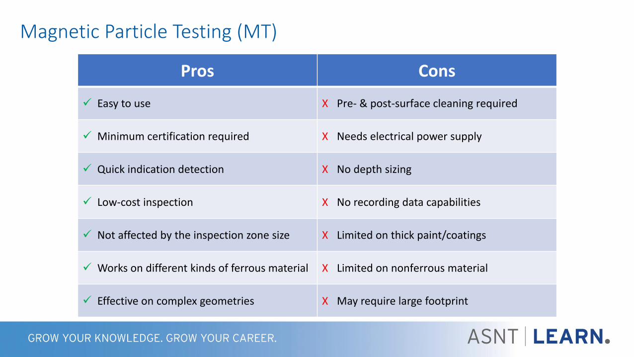
Pros Cons
✓ Easy to use X Pre- & post-surface cleaning required
✓ Minimum certification required X Needs electrical power supply
✓ Quick indication detection X No depth sizing
✓ Low-cost inspection X No recording data capabilities
✓ Not affected by the inspection zone size X Limited on thick paint/coatings
✓ Works on different kinds of ferrous material X Limited on nonferrous material
✓ Effective on complex geometries X May require large footprint

Liquid or Dry Penetrant Testing (PT)
• Surface-breaking in nonporous materials
• Applied penetrant is drawn into the surface- breaking defects
• Defects become visible from the dye or under UV light

Liquid Penetrant Testing (PT)
Pros Cons
✓ Easy to use X Pre- & post-surface cleaning required
✓ Minimum certification required X Limited on nonporous surface
✓ Show small surface-breaking defects X No depth sizing
✓ Low-cost inspection X No recording data capabilities
✓ Not affected by the inspection zone size X Limited sensitivity on rough surfaces
✓ Works on many types of materials X Chemical product handling
X May require large footprint

Eddy Current Testing (ECT)
• Surface-breaking in ferrous, surface and sub-surface in nonferrous metals
• Conductive metals
• Magnetic field from ECT probe induces small eddy currents in metal
• Discontinuities disturb the flow of eddy currents
• The “change” of current flow is detected and measured by instrumentation

Eddy Current Testing
Pros Cons
✓ Sensitive to surface and subsurface defects X Affected by magnetic permeability variations
✓ Capable of detection through multilayeredstructures
X Only effective on conductive materials
✓ Can detect through thin nonconductive surface coatings
X Careful acquisition technique
✓ Little pre-cleaning necessary X Signal interpretation requires skill
✓ Data can be recorded X Requires ECT instrumentation ($)

Eddy Current Array (ECA)
• Series of single ECT coils arranged in a single probe working as one
• One large probe as compared to a small, single-coil probe
• Coils are multiplexed to get specific data from each coil
• Individual coil data is combined in software to create 2D and 3D C-scan imaging
Single coil: slow n coils: n times faster

Eddy Current Array
Pros Cons
✓ Higher sensitivity on surface and subsurface defects X Affected by magnetic permeability variations
✓ Higher POD X Only effective on conductive materials
✓ Faster inspection X Operator dependent
✓ Wider coverage in a single-pass (higher resolution) X Signal interpretation requires skill
✓ Recording data for optional post-analysis and historicaltrending X Higher upfront cost ($$)
✓ Small footprint

How Does it Work?
32161
R
R
T
R
R
R
T
R
R
R
T
R
R
R
T
R
R
R
T
R
R
R
T
R
R
R
T
R
R
R
T
R
R
R
T
R
R
R
T
R
R
R
T
R
R
R
T
R
This combination is repeated in sequence
across the array of coils in the probe
Transmit Coil
T
Transverse
Receiver
R
Two Axial
Receivers
RR
Sca
n D
irec
tion

• Ability to have separate axial and transverse sensitive channels
Easy to Analyze
Axial sensitive channel
Transverse sensitive channel

• Channels can be combined into a single “merged” channel• Allows for fast data screening for 360° coverage
Merge Channel
Axial & transverse “merge” channel
Axial channel
Transverse channel

• 2019 ASME Section V, Article 8
• New appendices for ECA:• Appendix IX:
“Eddy current array (ECA) examination of ferromagnetic and nonferromagnetic MATERIALS for the detection of surface- breaking flaws”
• Appendix X:
“Eddy current array (ECA) examination of ferromagnetic and nonferromagnetic WELDS for the detection of surface-breaking flaws”
ASME Code Adoption

• General Requirements – Procedure and personnel qualification
• Equipment – Instrument, probes, standards
• Application reqs. – Speed, coated surface, data screening
• Technique – Essential variables, color palette, channels
• Calibration – Equipment and system
• Examination - Acquisition
• Evaluation - Analysis
• Documentation - Reporting
ASME Code Adoption

• Test panels are used to test system’s overall performance• Known as TAM Panels
• Also known as Sherwin or Magnaflux Test Panels
• Stainless steel 0.25 cm thick, 15 cm wide, 10 cm tall
• Strip of chrome plating has five variable size crack centers
• Other half has an oxide grit-blasted surface to monitor background fluorescence
TAM Panel

• Largest crack pattern is readily visible with low-sensitivity penetrant materials
• Smallest crack pattern is visible with high-sensitivity penetrant materials
• Can require more than one penetrant type to cover the full inspection
• This also translates to field testing limitations and POD
TAM Panel Example

• Largest crack pattern is clearly visible
• Smallest crack pattern is also visible with a high POD
• Only one scan is needed to cover the full inspection
• This translates to field testing capability of detection
TAM Panel Using ECA
Largest Crack Pattern
Smallest Crack Pattern

• Custom palette options give the user the ability to produce a large variety shadingcolor schemes using variations of red, gray, green, blue, and purple.
• Thresholds can be assigned to designate which voltage breaks in the color gradientoccur. This can be used to highlight flaws of interest and downplay other signals.
PT & MT Familiarity

Side by side examples

• Base metal crack
• Base metal root crack
• Wet fluorescent particle
Carbon Steel Weld

• Great detectability
• Excellent SNR
ECA Results

MT-Like Palette

• Aircraft stringer
• Wrought
• Stress crack
• Fluorescent dye
Aluminum

Stress Crack

• Aircraft stringer
• Wrought
• Long crack between holes
• Fluorescent dye
Aluminum

Long Axial Crack

• Wing spar
• Wrought
• Corrosion & cracking
• Visual
Aluminum

Corrosion
Axial Channel Transverse Channel
Both channels have like indications => Corrosion

Corrosion and Transverse Cracks
Axial Channel Transverse Channel
Transverse cracking in corrosion

• Engine ring
• Forged & rolled
• Machine tear
• Wet fluorescent particle
Stainless Steel

Machine Tear

• Small engine blade
• Cast & weld
• Tip crack
• Porosity on pressure side
• Fluorescent dye
Titanium

Porosity

Tip Crack
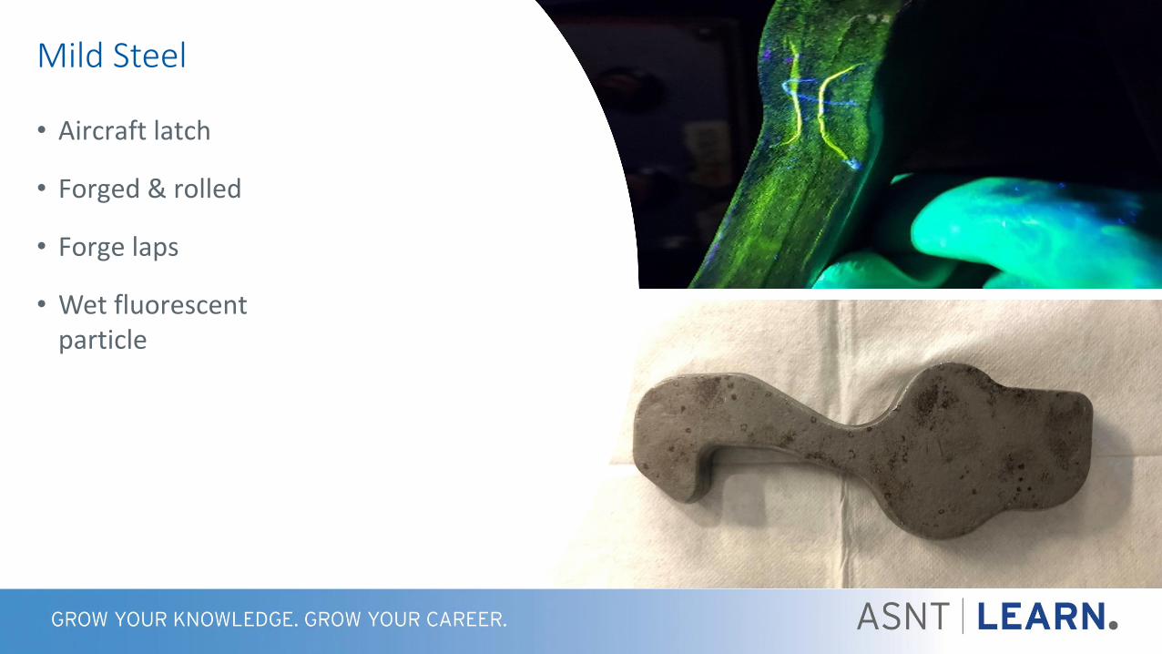
• Aircraft latch
• Forged & rolled
• Forge laps
• Wet fluorescent particle
Mild Steel

Forging Laps

• Wrought forging
• Forging lap
• Forging burst
• Fluorescent dye
Inconel 718

Forging Lap

Forging Burst

ECA Applications

• Widespread corrosion throughout
• Significant axial cracking
SCC in Carbon Steel

• Widespread corrosion throughout
• Significant axial cracking
SCC in Carbon Steel

Multimodal Damage
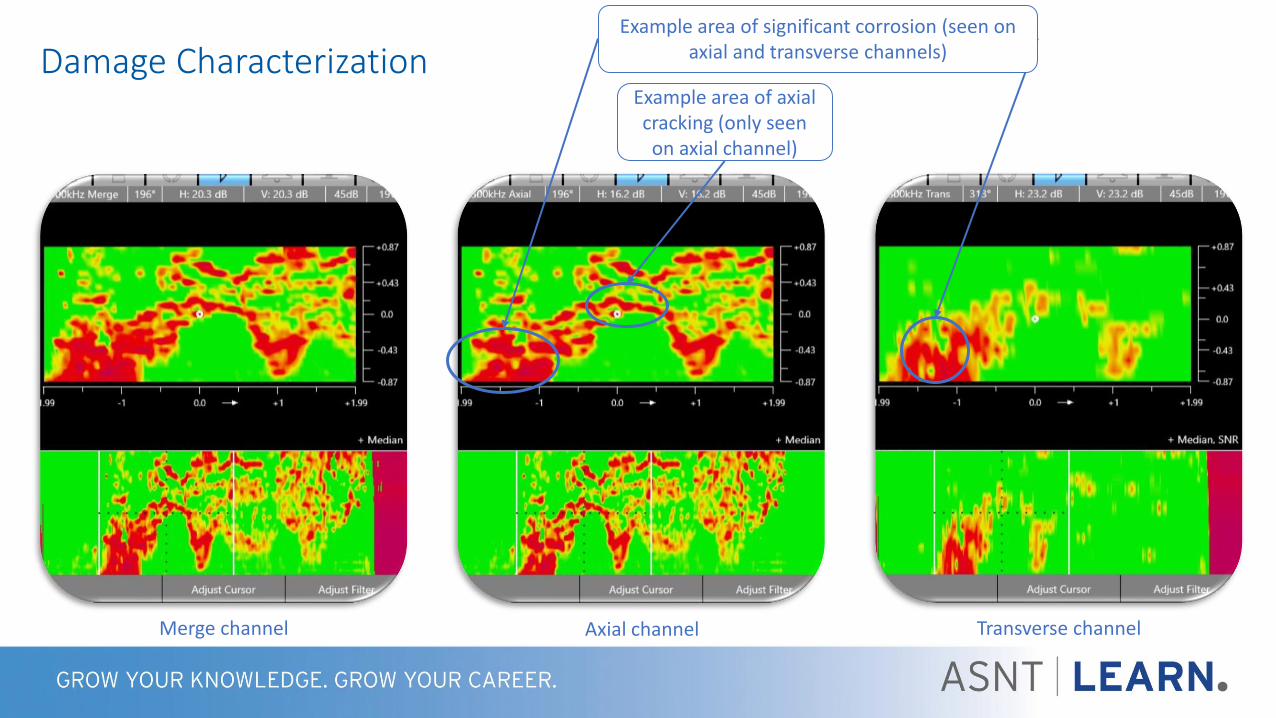
Damage Characterization
Axial channel Transverse channelMerge channel
Example area of axial cracking (only seen on axial channel)
Example area of significant corrosion (seen on axial and transverse channels)

• Replace MT/PT
• Inspect wheel contour in 3 passes or less
Train Wheels

• Tape probe with custom probe forms
• UHMW wear surface
• Customized color palette
Train Wheels

50

• 1087 reference standard
• 0.19 in. (4.8 mm) combined thickness
• 0.25 in. (6.35 mm) notch length
• Subsurface cracks stemming from rivets
Aircraft Multi-Layer Structures


Notches A & B
Rivet signal in view Rivet signals removed

• Aircraft corrosion
• Helicopter rotors
• Inspecting rows of fasteners in aircraft
• Chem mill cracking on airframes
• Ask yourself if a MT/PT inspection can be augmented by ECA?• Augment example: Perform ECA over large surface. Follow up with MT/PT in small areas
discovered by ECA.
And Many More….

Technique Comparison
MT PT ECT ECA
Effective on coating/paint surface No Limited Yes Yes
Pre & post cleaning Yes Yes No No
Chemical/consumables Yes Yes No No
Inspection speed Low Low Medium Very High
Sizing capabilities No No Yes Yes
Recording data No No Yes Yes
Post inspection data analysis No No Yes Yes
Trending capabilities No No Limited Yes
3D Imaging No No No Yes

Remember - eddy current is eddy current!
1. What is the minimum flaw size?
2. What is the frequency range?
3. Can I just use the C-scan?
4. How deep into the material can you detect flaws?
5. What is the sizing accuracy?
FAQ

• ECA can be used to bolster MT/PT inspections, especially for mission critical assets
• ASME code now allows for the use of ECA
• ECA has been demonstrated to provide superior results on a variety of materials andapplications
• Details such as flaw morphology can be analyzed and saved for historical tracking
• POD is higher as compared to conventional ECT
Conclusions

Thanks!
www.tb3ndt.com
Toni BaileyASNT & NAS 410 NDT Level III 92638Nital Etch, MT, PT, ET, UT, IRRSPASNT Region 2 – Directorwww.tb3ndt.com
Many thanks to Toni Bailey for providing samples and MT/PT results!

Additional Questions?Contact:
Nick Cardillo
Toni Bailey
www.tb3ndt.com

Thank you for participating!The American Society for Nondestructive Testing
1711 Arlingate LaneColumbus, Ohio 43228-0518
(614) 274-6003 | (800) 222-2768www.asnt.org
ASNT … Creating a Safer World!®