Week 8---Stress+Strian
42
CONCEPT OF STRESS CONCEPT OF STRESS normal (axial) and shear stresses normal (axial) and shear stresses
description
UNSW CVEN1300
Transcript of Week 8---Stress+Strian

CONCEPT OF STRESSCONCEPT OF STRESSnormal (axial) and shear stressesnormal (axial) and shear stresses
NORMAL STRESS NORMAL STRESS AND SHEAR STRESSAND SHEAR STRESS
Objectives:Objectives:a)a) Understand the concepts of normal and shear stressUnderstand the concepts of normal and shear stressb)b) U d t d th t f l t iU d t d th t f l t ib)b) Understand the concepts of normal strainsUnderstand the concepts of normal strainsc)c) Hooke’s LawHooke’s Law
Shear

PREDICTION OF PREDICTION OF STRUCTURAL BEHAVIOURSTRUCTURAL BEHAVIOUR
The behaviour of the whole structure is deduced The behaviour of the whole structure is deduced from the behaviour of its components.from the behaviour of its components.
The resistance of a material to deformation under load and other The resistance of a material to deformation under load and other influences is governed fundamentally by its atomic and molecular influences is governed fundamentally by its atomic and molecular
o t e be av ou o ts co po e ts.o t e be av ou o ts co po e ts.
influences is governed fundamentally by its atomic and molecular influences is governed fundamentally by its atomic and molecular structure.structure.
The material deformation depends on many factors: The material deformation depends on many factors: the load to the load to p yp ywhich it is subjected, whether the load is steady or fluctuating, which it is subjected, whether the load is steady or fluctuating, the duration of loading or heating, etcthe duration of loading or heating, etc..
From a knowledge of the properties of the material we can deriveFrom a knowledge of the properties of the material we can derivethe deformation characteristics of simple structural components. the deformation characteristics of simple structural components. i.e. i.e. BEAMS, COLUMNS, TIEBEAMS, COLUMNS, TIE--RODS, COMPRESSION STRUTSRODS, COMPRESSION STRUTS(commonly referred to as (commonly referred to as members/barsmembers/bars))

PREDICTION OF PREDICTION OF STRUCTURAL BEHAVIOURSTRUCTURAL BEHAVIOUR
In engineering construction elements of aIn engineering construction elements of astructure must exist with definite physical sizes. structure must exist with definite physical sizes.
These elements must be properly proportionedThese elements must be properly proportionedto resist the forces that may be imposed uponto resist the forces that may be imposed uponto resist the forces that may be imposed uponto resist the forces that may be imposed uponthem.them.
In engineering practice, economy is desirableIn engineering practice, economy is desirableWhen selecting materials.When selecting materials.

i.e.i.e. Steel Structures Steel Structures b l bb l b l t t til t t tibeams, columns, beambeams, columns, beam--columns, struts, tiescolumns, struts, ties

FORCESFORCESFORCESFORCESOne important objective in strength of materials is the investigation ofOne important objective in strength of materials is the investigation ofOne important objective in strength of materials is the investigation ofOne important objective in strength of materials is the investigation ofthe internal resistance of a body (i.e. the forces set up internally tothe internal resistance of a body (i.e. the forces set up internally tobalance the externally applied forces)balance the externally applied forces)y pp )y pp )
These are called internal actions.These are called internal actions.
If a body as a whole is in equilibrium any part of it must also be inIf a body as a whole is in equilibrium any part of it must also be inequilibrium. For such parts of a body, however, some of the forcesequilibrium. For such parts of a body, however, some of the forcesq p yq p ynecessary to maintain equilibrium must act at the face of the section. necessary to maintain equilibrium must act at the face of the section. These considerations lead to the following fundamental conclusion:These considerations lead to the following fundamental conclusion:
The externally applied forces to one side of an arbitrary cut mustThe externally applied forces to one side of an arbitrary cut mustbe balanced by the internal forces developed at the cut. be balanced by the internal forces developed at the cut.
The external forces are balanced by the internal forces.The external forces are balanced by the internal forces.

SIMPLY SUPPORTED BEAM SIMPLY SUPPORTED BEAM –– free body diagramfree body diagram
cross-sectionUDL
beamA B
Lx
A B
UDL
MS
MNFBD S – shear stress resultant
N – axial force stress resultantM – bending moment stress
xRA
gresultant

FORCESFORCESExternal forces External forces
FORCESFORCESExternal forces External forces
–– forces imposed on the bodyforces imposed on the body
Internal forcesInternal forces–– act between two different portions of the body under act between two different portions of the body under
consideration. consideration. Imagine any plane within the material, then Imagine any plane within the material, then the force transmitted across this plane is an internal forcethe force transmitted across this plane is an internal forcethe force transmitted across this plane is an internal force.the force transmitted across this plane is an internal force.(recall free body diagram concept)(recall free body diagram concept)
can also occur independently of external forces (can also occur independently of external forces (i e if the i e if the –– can also occur independently of external forces (can also occur independently of external forces (i.e.if the i.e.if the central portion of a bar is heated it tends to expand but is central portion of a bar is heated it tends to expand but is restrained by the surrounding material restrained by the surrounding material –– thus, the central thus, the central
i i i i i ii i i i i ipart will be in compression while the outer par will be in part will be in compression while the outer par will be in tensiontension))

CONCEPT OF STRESSCONCEPT OF STRESSCONCEPT OF STRESSCONCEPT OF STRESSF5F1
yE l f F2
z
External forces acting on a body
F4F3x
yF1 Force
ResultantR
z
F
F2
M
Internal forces acting on a Cross-Section
x F3M
MomentResultant
g

NORMAL and SHEAR STRESSNORMAL and SHEAR STRESS
σz = lim ∆ A 0
∆ Fz∆ A
τzx = lim ∆ A 0
∆ Fx∆ A
τzy = lim ∆ A 0
∆ Fy∆ A
Units: Units: N/mN/m22 ( ( ≡≡ 1 Pa)1 Pa)N/mmN/mm22 ( ( ≡≡ 1 MPa)1 MPa)
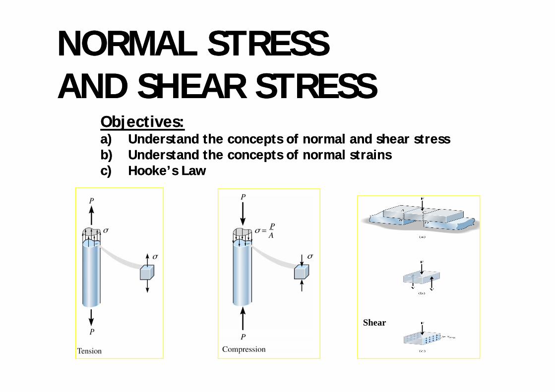
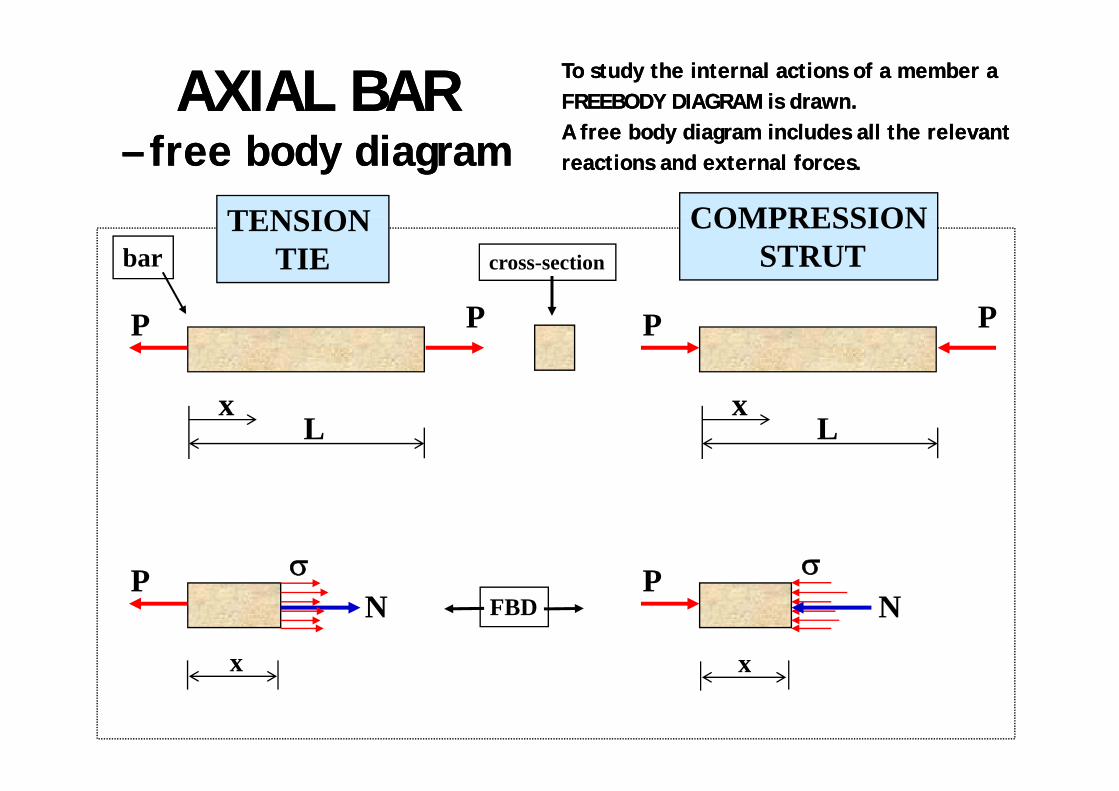
NORMAL AND SHEAR STRESSESNORMAL AND SHEAR STRESSESacting on a Crossacting on a Cross--SectionSection
yF1
Normal (axial) stresses1. NOTE:NOTE:
Force Resultant RForce Resultant R can be can be resolved in 2 components:resolved in 2 components:
zF2
pp
1.1. Acting perpendicular to the cross Acting perpendicular to the cross sectionsection(NORMAL OR AXIAL FORCE)(NORMAL OR AXIAL FORCE)
xF3
2
2.2. Acting parallel to the cross sectionActing parallel to the cross section(SHEAR FORCE)(SHEAR FORCE)
yF1
2.
zF2
xShear
(tangential) stresses F3

AVERAGE NORMAL STRESSAVERAGE NORMAL STRESSAVERAGE NORMAL STRESSAVERAGE NORMAL STRESS
σ = PA

CONCEPT OF NORMAL CONCEPT OF NORMAL AXIAL STRESSAXIAL STRESS
•• A point force is an idealisation we make, in reality forces are A point force is an idealisation we make, in reality forces are applied over a certain area applied over a certain area –– similar to pressure.similar to pressure.
h l h lh l h l•• At a crossAt a cross--section the internal action must have a ‘force resultant’ section the internal action must have a ‘force resultant’ equal to P.equal to P.
•• The internal action can be represented as a point force or as a The internal action can be represented as a point force or as a ‘stress’‘stress’‘stress’.‘stress’.
•• A stress is defined as the intensity over an area of force A stress is defined as the intensity over an area of force –– similar similar to the concept of pressure.to the concept of pressure.Normal or direct stress is produced by a force which is ‘normal’ to Normal or direct stress is produced by a force which is ‘normal’ to •• Normal or direct stress is produced by a force which is ‘normal’ to Normal or direct stress is produced by a force which is ‘normal’ to the plane of the crossthe plane of the cross--section on which the force acts. section on which the force acts. It is denoted s (sigma) and is defined by:It is denoted s (sigma) and is defined by:
dPPδσ lim Units Pascal (Pa) = N/m2
dAAA==
→ δσ
δ 0lim
We use MPa = N/mm2 or 103 kN/m2

CONCEPT OF NORMAL CONCEPT OF NORMAL AXIAL STRESSAXIAL STRESSAXIAL STRESSAXIAL STRESSThe Resultant of the Direct StressThe Resultant of the Direct Stress over the crossover the cross--section must be equal to section must be equal to the internal actionthe internal action, in this , in this
∫= dAP σ
qq ,,case the case the axial force Paxial force P::
∫A
dAP σ
If the stress distribution is If the stress distribution is ‘uniform’‘uniform’ over the over the crosscross--section, thensection, then
AP /=σ(constant over the cross(constant over the cross--section)section)

CONCEPT OF NORMAL AXIAL CONCEPT OF NORMAL AXIAL STRESSSTRESS
PConsider a bar of length Consider a bar of length LLacted by forces acted by forces PP at each end.at each end.
P
σL
σL
PP

CONCEPT OF NORMAL AXIAL CONCEPT OF NORMAL AXIAL STRESSSTRESS
h l l d d h h l hh l l d d h h l h
STRESSSTRESSWhen an element is loaded so that the normal stresses thatWhen an element is loaded so that the normal stresses thatexist are one dimensional this is known as an axial member exist are one dimensional this is known as an axial member (i.e. axially stressed)(i.e. axially stressed)
P P P PTENSION TIE COMPRESSION STRUTP P P P
P Pσ σPN
P
x x
N
NOTE:NOTE: One must investigate buckling when compressive loads are considered. One must investigate buckling when compressive loads are considered. Sl d b h d b kl id d ll Sl d b h d b kl id d ll Slender members have a tendency to buckle sideways and collapse. Slender members have a tendency to buckle sideways and collapse. We will assume our members are chunky or stocky and cannot buckle.We will assume our members are chunky or stocky and cannot buckle.
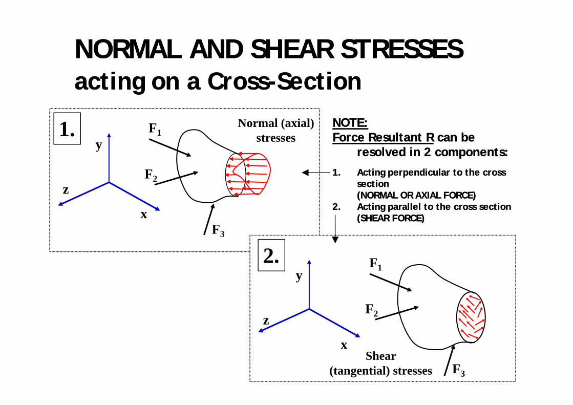
AXIALAXIAL BARBAR To study the internal actions of a member aTo study the internal actions of a member aFREEBODY DIAGRAM is drawn. FREEBODY DIAGRAM is drawn. A f b d di i l d ll th l tA f b d di i l d ll th l t–– free body diagramfree body diagram
TENSION COMPRESSION
A free body diagram includes all the relevantA free body diagram includes all the relevantreactions and external forces.reactions and external forces.
bar cross-section
TENSION TIE
COMPRESSIONSTRUT
P P P P
Lx
Lx
P σP σ P
x
NP
N
x
σFBD
xx

EXAMPLEEXAMPLE
AFD
Average Normal Stress:Average Normal Stress:
PBC 30 (103) N 85 7 MPσBC = PBCA
30 (10 ) N(0.035 m)(0.010 m)
= = 85.7 MPa

CONCEPT OF SHEAR STRESSCONCEPT OF SHEAR STRESSCONCEPT OF SHEAR STRESSCONCEPT OF SHEAR STRESSIf a If a Shear Force ‘S’Shear Force ‘S’ acts on a crossacts on a cross--section the associatedsection the associatedIf a If a Shear Force SShear Force S acts on a crossacts on a cross--section the associatedsection the associatedstresses are tangential to the crossstresses are tangential to the cross--section and are calledsection and are called
“Shear Stresses” “Shear Stresses” denoted by denoted by tt (tau)(tau)“Shear Stresses” “Shear Stresses” denoted by denoted by tt (tau).(tau).
dSS==
δτ limS
τ dAAA→ δδ 0τ
The distribution of shear stresses is The distribution of shear stresses is often complex but we can get an often complex but we can get an AS /=τoften complex, but we can get an often complex, but we can get an average measure from:average measure from:
ASav /=τ
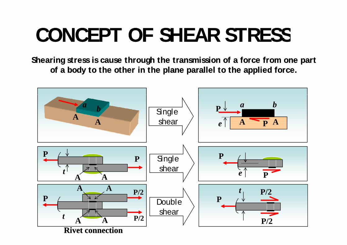
CONCEPT OF SHEAR STRESSCONCEPT OF SHEAR STRESSCONCEPT OF SHEAR STRESSCONCEPT OF SHEAR STRESSShearing stress is cause through the transmission of a force from one part Shearing stress is cause through the transmission of a force from one part
f b d h h i h l ll l h li d ff b d h h i h l ll l h li d fof a body to the other in the plane parallel to the applied force.of a body to the other in the plane parallel to the applied force.
A A
a b P
PA A
a b
eSingle shearA PA Aeshear
P
P
e
Single sheart
A A
P P
Pt P/2
PP/2A A
Double
A A
P/2t P/2A Ashear
Rivet connectionRivet connection

AVERAGE SHEAR STRESSAVERAGE SHEAR STRESSSingle Shear
Double Shear Double Shear

EXAMPLEEXAMPLE
Design for the pins:g p

EXAMPLE (Continued)EXAMPLE (Continued)EXAMPLE (Continued)EXAMPLE (Continued)

STRAIN STRAIN STRAIN STRAIN Objectives:Objectives:jja)a) Understand the concept of normal and shear Understand the concept of normal and shear
strain, andstrain, and,,b)b) Apply the concept to determine the strains for Apply the concept to determine the strains for
various types of problemsvarious types of problemsyp pyp p

Concept of StrainConcept of StrainppIf a body is displaced such that its shape and sizeIf a body is displaced such that its shape and sizey p py p pdoes not change, it has gone a does not change, it has gone a ‘rigid body’‘rigid body’displacementdisplacement
Transverse displacement
displacement.displacement.
- Transverse displacement
- Rotation - Rotation RIGID BODY
MOTION MOTION

Deformation of a bar under Deformation of a bar under an axial forcean axial forceWhen a body undergoes a set of displacements such that itsWhen a body undergoes a set of displacements such that itssize or shape is changedsize or shape is changed then the body has undergone somethen the body has undergone some
Example 1
sort of sort of ‘deformation’‘deformation’..
Example 1 T TExtension of a bar
under an axial (tensile) force(tensile) force
Change in length - elongation
C C Contraction of a bar under an axial
(compressive) force(compressive) force
Change in length - contraction

Concept of StrainConcept of StrainConcept of StrainConcept of Strain“Strain”“Strain” is a quantity which is used tois a quantity which is used to“Strain”“Strain” is a quantity, which is used tois a quantity, which is used to
measure the measure the amountamount and and directiondirection of of the the d f id f ideformation.deformation.
It is defined as It is defined as the ratiothe ratioof of the deformationthe deformation to the to the original sizeoriginal size of the body.of the body.
There are two sorts of strains:There are two sorts of strains:
o o t e de o at ot e de o at o to t e to t e o g al s eo g al s e o t e body.o t e body.
-- NORMAL STRAINNORMAL STRAIN
-- SHEAR STRAIN SHEAR STRAIN

NORMAL (direct) STRAINNORMAL (direct) STRAIN( )( )
The Normal StrainThe Normal Strainis a measure of the change in length. is a measure of the change in length. g gg gIt is denoted by It is denoted by ‘‘εε’ (epsilon)’ (epsilon)..
dde
dx
L eL e
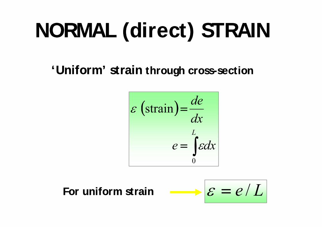
NORMAL (direct) STRAINNORMAL (direct) STRAINNORMAL (direct) STRAINNORMAL (direct) STRAIN
‘Uniform’ strain‘Uniform’ strain through crossthrough cross--sectionsection
( ) = destrainε ( )
∫L
dx
∫= dxe0
ε
Le /=εFor uniform strainFor uniform strain Le /=εFor uniform strainFor uniform strain
MECHANICAL PROPERTIES MECHANICAL PROPERTIES OF MATERIALS OF MATERIALS
Obj ti :Obj ti :Objectives:Objectives:a)a) Understand how to measure the stress and Understand how to measure the stress and a)a) Understand how to measure the stress and Understand how to measure the stress and
strain through experiments, andstrain through experiments, and
b)b) Correlate the behavior of some engineering Correlate the behavior of some engineering materials to the stressmaterials to the stress--strain diagram.strain diagram.
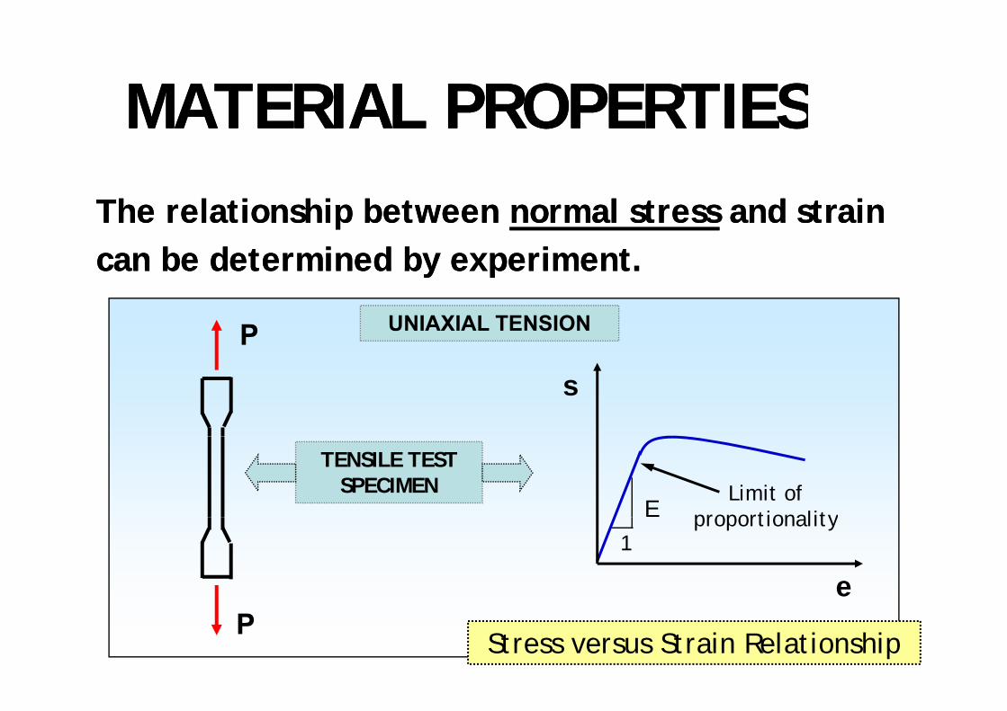
MATERIAL PROPERTIESMATERIAL PROPERTIESMATERIAL PROPERTIESMATERIAL PROPERTIESThe relationship between The relationship between normal stressnormal stress and strainand straincan be determined by experiment.can be determined by experiment.
P UNIAXIAL TENSION
y py p
s
TENSILE TEST SPECIMEN Limit of
proportionalityE proportionality1
eP
Stress versus Strain Relationship

TENSION AND TENSION AND COMPRESSION TESTCOMPRESSION TEST
SpecimenSpecimenSpecimenSpecimen
Equipment

APPLICATIONSAPPLICATIONSAPPLICATIONSAPPLICATIONS

STRESSSTRESS--STRAIN STRAIN DIAGRAMDIAGRAM
It is common practice to plot diagrams on which aIt is common practice to plot diagrams on which arelationship between stress and strain for a particular testrelationship between stress and strain for a particular testrelationship between stress and strain for a particular testrelationship between stress and strain for a particular test
in tension and compression are obtained.in tension and compression are obtained.
These diagrams establish a relationship between stress and strain,These diagrams establish a relationship between stress and strain,and for most practical purposes are assumed to be independent ofand for most practical purposes are assumed to be independent ofthe size of the specimen or its gauge lengththe size of the specimen or its gauge length
Experimentally obtained stressExperimentally obtained stress--strain diagrams depend on:strain diagrams depend on:
the size of the specimen or its gauge length.the size of the specimen or its gauge length.
p yp y g pg p
-- Speed of testSpeed of testT t t hi h t t d t dT t t hi h t t d t d-- Temperature at which test was conductedTemperature at which test was conducted
-- Several other variablesSeveral other variables

ASPECTS of STRESSASPECTS of STRESS--STRAIN DIAGRAMSTRAIN DIAGRAM
BEHAVIOUR OF Stress − σConstant stress-
plastic rangeHardening
rangeMILD STEELσult
σy εy – yield strainProportional
g
Strain ε
y yεsh - strain hardening
Proportional limit
εy Strain − εεsh
Points worth noting on a stressPoints worth noting on a stress--strain diagram include:strain diagram include:Points worth noting on a stressPoints worth noting on a stress strain diagram include:strain diagram include:-- -- PROPORTIONAL LIMIT (yield point)PROPORTIONAL LIMIT (yield point)-- -- ULTIMATE STRENGTHULTIMATE STRENGTH σσ ltlt-- ULTIMATE STRENGTH, ULTIMATE STRENGTH, σσultult
-- -- YIELD STRESS, YIELD STRESS, σσyy

STRESSSTRESS--STRAIN DIAGRAMSTRAIN DIAGRAMSTRESSSTRESS STRAIN DIAGRAMSTRAIN DIAGRAM
Note the critical Note the critical status for strength status for strength specificationspecificationpp•• proportional limitproportional limit•• elastic limitelastic limit•• yield stressyield stressyield stressyield stress•• ultimate stressultimate stress•• fracture stressfracture stress

STRESSSTRESS--STRAIN STRAIN DIAGRAMDIAGRAM
Two types of diagrams can be recognised:Two types of diagrams can be recognised:
-- DUCTILEDUCTILE materials widely used in construction (steel)materials widely used in construction (steel)
BRBR-- BRITTLEBRITTLE materials (concrete, glass)materials (concrete, glass)
BRITTLE (limited deformation)σ
BRITTLE (limited deformation)
DUCTILE (deform considerably)
ε
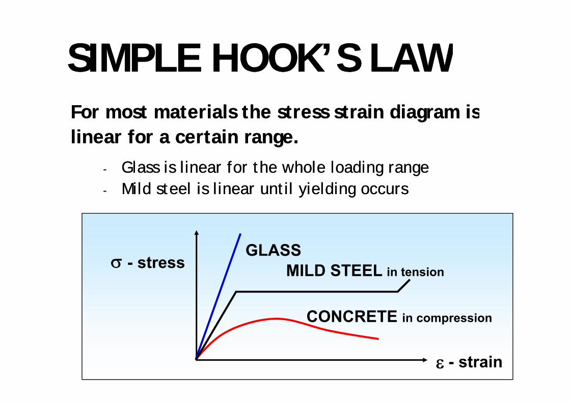
SIMPLE HOOK’S LAWSIMPLE HOOK’S LAWSIMPLE HOOK S LAWSIMPLE HOOK S LAWFor most materials the stress strain diagram isFor most materials the stress strain diagram isFor most materials the stress strain diagram isFor most materials the stress strain diagram islinear for a certain range.linear for a certain range.
-- Glass is linear for the whole loading rangeGlass is linear for the whole loading range-- Mild steel is linear until yielding occursMild steel is linear until yielding occurs
GLASSσ
GLASSMILD STEEL in tension- stress
CONCRETE in compression
ε - strain

SIMPLE HOOK’S LAWSIMPLE HOOK’S LAWSIMPLE HOOK S LAWSIMPLE HOOK S LAWThe stress and strain can be considered linear up to aThe stress and strain can be considered linear up to aThe stress and strain can be considered linear up to aThe stress and strain can be considered linear up to acertain point. certain point. This generalisation is known as This generalisation is known as Hooke’s LawHooke’s Law and states:and states:
εσ /=Eεσ E= The stress is directlyThe stress is directlyproportional to strainproportional to strain
This generalisation is known as This generalisation is known as Hooke s LawHooke s Law and states:and states:
proportional to strainproportional to strain
E is Young’s Modulus, units E is Young’s Modulus, units MPa (N/mmMPa (N/mm22))200 000 200 000 210 000 MPa for Steel210 000 MPa for Steel200,000 200,000 -- 210,000 MPa for Steel210,000 MPa for Steel20,000 20,000 -- 40,000 MPa for Concrete40,000 MPa for Concrete εε is dimensionlessis dimensionless
γτ G=E
For Shear Stresses
( )μ+=12EGG G is the is the Shear ModulusShear Modulus (80,000 MPa for steel)(80,000 MPa for steel)

ELASTICELASTIC--PLASTIC MODEL PLASTIC MODEL for STEELfor STEEL
σ
Yielding
σ
σσy
UnloadingYield Stress
ε
gE
εPermanent Set
Th t t i l ti hiTh t t i l ti hiThe stress strain relationshipThe stress strain relationship is approximated byis approximated bytwo straight lines.two straight lines.

STRESSSTRESS--STRAIN STRAIN DIAGRAMDIAGRAM
σ
Yield Point
ε0.2% offset0. % o se
For materials without a specified yield or proportional limit, For materials without a specified yield or proportional limit, the yield point is specified by taking a 0.2% offset the yield point is specified by taking a 0.2% offset and drawing a parallel to the slope of the curve. and drawing a parallel to the slope of the curve. The elastic limit corresponds closely to the proportional limit of the material.The elastic limit corresponds closely to the proportional limit of the material.

UNIAXIAL STRESSUNIAXIAL STRESSUNIAXIAL STRESSUNIAXIAL STRESS
AP /=σUniform stress:
Le /=εUniform strain: Le /=ε
εσ E
Uniform strain:
Hooke’s Law: εσ E=Hooke s Law:
eEP=∴ eEAP =
PLeEA
=LA
eL EA