Week 3 - cse.buffalo.edustevko/courses/cse490/spring11/files/... · – Enter source code using any...
29
Week 3
Transcript of Week 3 - cse.buffalo.edustevko/courses/cse490/spring11/files/... · – Enter source code using any...

Week 3

Required CAD Tools
• Download and install the Xilinx ISE WebPack
V12.4. The Xilinx download is very large. If you
have any problem downloading the product
let me know !!!let me know !!!
• Go to
http://www.xilinx.com/tools/webpack.htm
• And make sure to download and install ISE
Design Suite - 12.4 Full Product Installation

• Notes:
– When installing the Xilinx ISE WebPack, you can
just perform the standard, default installation, and
choose the free edition.
– Follow the instructions to have the license after
you creating an account.

Unit under test
• Unit under test (UUT) is connected to a test fixture
– Inputs are applied to test fixture
– Outputs monitored– Outputs monitored
• Test Fixture
– Provides for efficient testing of circuit
– Setup in Xilinx as an HDL file
– ISIM (simulator)uses this to know what inputs to apply to the UUT

`timescale 1ns / 1ps
module test1;
// Inputs
reg a;
reg b;
reg c;
// Outputs
wire s;
wire cout;
// Instantiate the Unit Under Test (UUT)
fulladder uut (
.a(a),
module
fulladder(a,b,c,s,cout);
input a,b,c;
output s,cout;
xor #1
g1(w1, a, b),
g2(s, w1, c);
and #1
g3(w2, c, b),.a(a),
.b(b),
.c(c),
.s(s),
.cout(cout)
);
initial begin
// Initialize Inputs
a = 1; b = 0; c = 0;
// Wait 100 ns for global reset to finish
#100;
a = 0;b = 0; c = 0;
end
endmodule
g3(w2, c, b),
g4(w3, c, a),
g5(w4, a, b);
or #1
g6(cout, w2, w3,
w4);
endmodule

Simulation
• The simulation is an event-driven, time-ordered depiction of the circuit’s behavior under the prescribed specifications.
• Structureinitial
beginbegin
Simulation
End
• Assignments– Syntax
• Input_Name = Value;

• Integral Delay– #n;
– Delays action by n time units (as defined by the timescale)
• In other words…
• n time units after the current time, the described event will take place
• Timescale• Timescale– Compiler Directive
– Preceded by `
– ` timescale reference_time_unit / time_precision• Note, this is not an apostrophe
– The integral delay is in units of the reference_time_unit.

Identifiers
• Names given to hardware objects– Wires (busses)
– Registers
– Memories
– Modules
• Alphanumeric
• May Include:• _
• $
• May NOT Start With:• Number
• $
• Examples
- 4’b1011
- 8’hfe902a30
- 2’d37 � Same as 37 (default)
- 4’h a729
- ‘d 62923
- 8’b 1101zzzz
-16’h x
• A bit in the simulation may take one of four values:
- 1 (true)
- 0 (false)
- X (unknown)
-Z (High Impedance)
-Comments
• Single Line Comments• $
Numbers
• Syntax– Sized
• Size’Format Number
• Size
• Number of digits
• Format (Base)– h (Hexadecimal)
– d (Decimal) Default
– o (Octal)
– b (Binary)
• Unsized– ’Format Number
• Number– Number specified
• Single Line Comments
- Comment preceded by //
•Multiple Line Comments
-Comment encapsulated by /* and */
-Vectors
-wire and reg may be declared as multibit
-[expression_1 : expression_2]
-Example : A[3:0]
-Left expression is MSB, right is LSB
-Expression must be constant, but may contain
-Constants
-Operators
-parameters

Example to simulate Fulladder example
initial
begin
#10 a=0; b=0; c=0;
#10 a=1;
#10 b=1;
#10 c=1; a=0;
#10 a=1;
End
module fulladder(a,b,c,s,cout);
input a,b,c;
output s,cout;
xor
g1(w1, a, b),
g2(s, w1, c);
and
g3(w2, c, b),
g4(w3, c, a),
g5(w4, a, b);
or
g6(cout, w2, w3,
w4);
endmodule
Text Output (Icarus Verilog)
# 0 a=x, b=x, c=x, s=x, cout=x
# 10 a=0, b=0, c=0, s=0, cout=0
# 20 a=1, b=0, c=0, s=1, cout=0
Waveform
# 30 a=1, b=1, c=0, s=0, cout=1
# 40 a=0, b=1, c=1, s=0, cout=1
# 50 a=1, b=1, c=1, s=1, cout=1

Same simulation for fullbitadder with # delays, i.e.:
module fulladder() ;wire w1, w2, w3, w4, s, cout;
reg a, b, c;
xor #1
g1(w1, a, b),
g2(s, w1, c);
and #1
g3(w2, c, b),
g4(w3, c, a),
g5(w4, a, b);
or #1
g6(cout, w2, w3, w4);
Text Output (Icarus Verilog)
# 0 a=x, b=x, c=x, s=x, cout=x
# 10 a=0, b=0, c=0, s=x, cout=x
# 12 a=0, b=0, c=0, s=0, cout=0
# 20 a=1, b=0, c=0, s=0, cout=0
# 22 a=1, b=0, c=0, s=1, cout=0
# 30 a=1, b=1, c=0, s=1, cout=0
# 32 a=1, b=1, c=0, s=0, cout=1
# 40 a=0, b=1, c=1, s=0, cout=1
# 41 a=0, b=1, c=1, s=1, cout=1
# 42 a=0, b=1, c=1, s=0, cout=1
# 50 a=1, b=1, c=1, s=0, cout=1
# 52 a=1, b=1, c=1, s=1, cout=1
Simulation
initial
begin
#10 a=0; b=0; c=0;
#10 a=1;
#10 b=1;
#10 c=1; a=0;
#10 a=1;
Endg6(cout, w2, w3, w4);
endmodule
Waveform
Comment
or #1 // Or gate with a delay of one time unit
g6(cout, w2, w3, w4);

module fulladder(a,b,c,s,cout);
input a,b,c;
output s,cout;
xor #1
g1(w1, a, b),
g2(s, w1, c);
and #1
g3(w2, c, b),
g4(w3, c, a),
g5(w4, a, b);
or #1
g6(cout, w2, w3, w4);
endmodule
module fourBitAdder(x,y,s,cout,cin);input [3:0] x,y;output [3:0] s;input cin;output cout;wire c[3:0];fulladder f0 (x[0],y[0],cin,s[0],c[0]);fulladder f1 (x[1],y[1],c[0],s[1],c[1]);fulladder f2 (x[2],y[2],c[1],s[2],c[2]);fulladder f3 (x[3],y[3],c[2],s[3],cout);
endmoduleSimulation
Waveform
initial
begin
#20 a=2; b=3; cin=0;
#20 a=1; b=7; cin=0;
end
Text Output
# 0 a= x, b= x, c=x, s= x, cout=x
# 20 a= 2, b= 3, c=0, s= x, cout=x
# 22 a= 2, b= 3, c=0, s= X, cout=0
# 23 a= 2, b= 3, c=0, s= 5, cout=0
# 40 a= 1, b= 7, c=0, s= 5, cout=0
# 42 a= 1, b= 7, c=0, s= 2, cout=0
# 43 a= 1, b= 7, c=0, s=12, cout=0
# 45 a= 1, b= 7, c=0, s= 0, cout=0
# 47 a= 1, b= 7, c=0, s= 8, cout=0

• iverilog– Available on the CSE systems
• Using iverilog– Enter source code using any editor
– Save using .v exention– Save using .v exention
• Compile– iverilog -t vvp filename.v -o out_filename
– Note that neglecting to specify the output filename (-o out_filename), iverilog will
– output to a.out.
– View Results
– vpp out filename

Simulation in Icarus VerilogTasks
– Monitor
– Monitors & displays the specified entities when the values change
– The extra commas add spaces in the output
– Format
• %b � bit
• %d � decimal
• %h � hexadecimal
time
– Indicates the current time
– The simulation will display the time when an event occurs
– Useful Tips for Simulation in ICARUS Verilog
Examples
initial
begin$monitor($time,,"a=%d, b=%d, c=%b, s=%d, cout=%b",a,b,cin,s,cout);
#20 a=2; b=3; cin=0;
#20 a=1; b=7; cin=0;
$display($time,,"a=%d, b=%d, c=%b, s=%d, cout=%b",a,b,cin,s,cout);
end
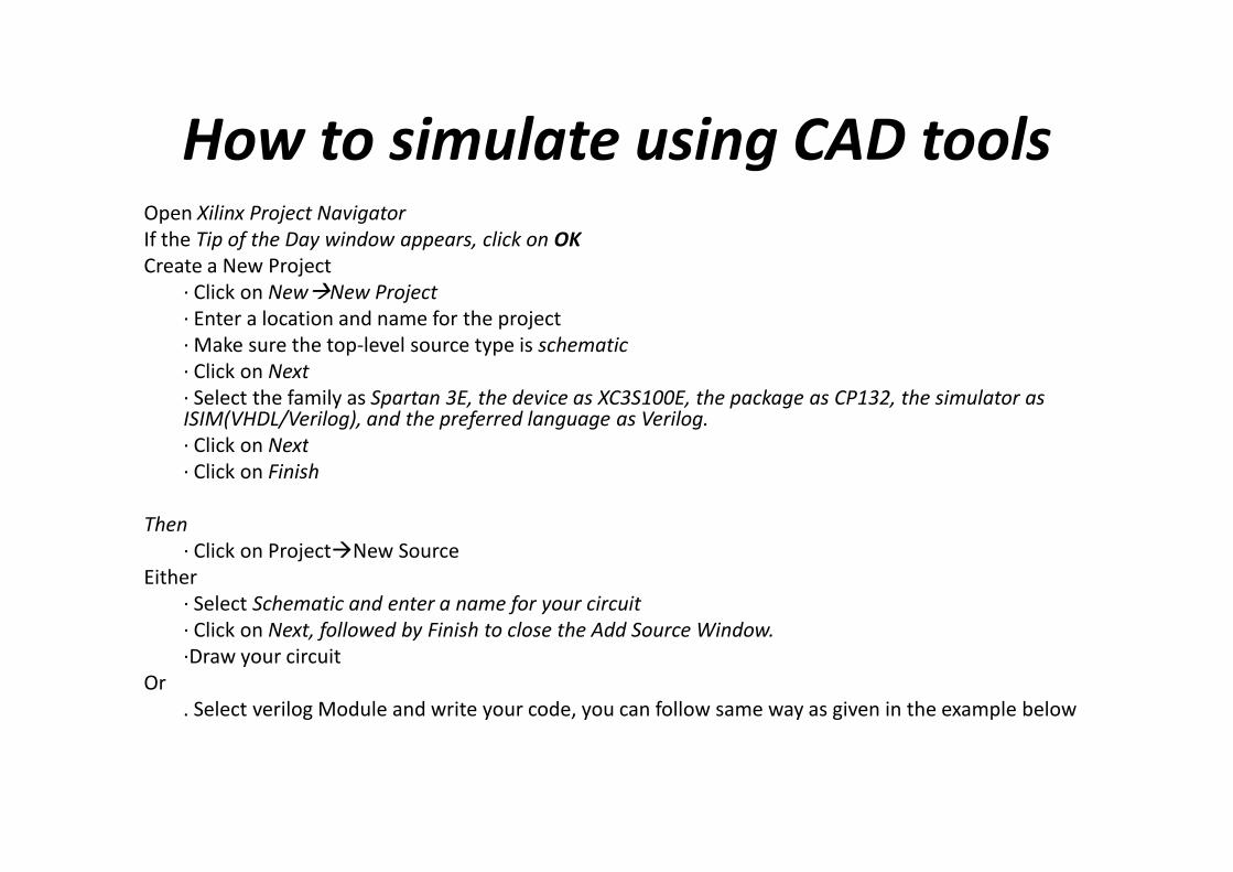
How to simulate using CAD toolsOpen Xilinx Project Navigator
If the Tip of the Day window appears, click on OK
Create a New Project
· Click on New�New Project
· Enter a location and name for the project
· Make sure the top-level source type is schematic
· Click on Next
· Select the family as Spartan 3E, the device as XC3S100E, the package as CP132, the simulator as ISIM(VHDL/Verilog), and the preferred language as Verilog.
· Click on Next· Click on Next
· Click on Finish
Then
· Click on Project�New Source
Either
· Select Schematic and enter a name for your circuit
· Click on Next, followed by Finish to close the Add Source Window.
·Draw your circuit
Or
. Select verilog Module and write your code, you can follow same way as given in the example below

Figure 1: Verilog Module

• Create the Test Fixture by
· Click on Project�New Source
· Select verilog Test Fixture
· choose the test file name and click on Next.
SimulatingtheCircuit
· choose the test file name and click on Next.
·Select the module to be tested, in our case it is the fulladderModule
. Click Next, followed by Finish.
• The test file will be generated automatically, as in the figure below

Figure 2: Verilog Test Fixture

Simulating the Circuit
• Click on the Design tab in the upper left window.
• Select Simulation at the top of the tab.
• Select the test file from the hierarchy tab (if necessary) by clicking on the + to the left of xc3s100e-5cp132.
• In the Processes window, expand the list of options for the ISIM simulator (if necessary) by clicking on the + to the left, ISIM simulator (if necessary) by clicking on the + to the left, double click on behavriol check syntax then double click on simulate behavriol model in the same tab.
• The ISIM will be opened and you can find all the test result.
• To know more about ISIM, refer to the tutorial:– http://www.xilinx.com/support/documentation/sw_manuals/xil
inx11/ug682.pdf

Figure3: ISIM GUI

Behavioral Modeling
Assignment Operator
• Operator: ASSIGN
• Continuous Assignment
• May be omitted for implicit assignments Full Adder Example
Bitwise Logical Operators
• Bitwise AND &
• Bitwise OR |
• Bitwise Invervsion ~
• Putting It All Together– Simple Example
– assign f = ~x & y | x & ~y;
module fulladder(a,b,cin,s,cout);
output s, cout;
input a,b,cin;
s = (~a & ~b & cin) | (~a & b & ~cin) |
(a & ~b & ~cin) | (a & b & cin);
cout = (a & b) | (a & cin) | (b & cin);
endmodule

Can Structural & Behavorial Verilog
be Combined?
Yes, Example
`timescale 1ns / 1ps
module test(f,a,b,s);
output f; // When s=0, f=a or b
input a,b,s; // When s=1, f=a and binput a,b,s; // When s=1, f=a and b
and g1 (w1,a,b);
or g2 (w2,a,b);
mux m1(f,w1,w2,s);
endmodule
module mux(y, d1, d0, s);
output y;
input d1, d0, s;
assign y = s ? d1 : d0;
endmodule

• The Conditional Operator
• Conditional Operator (?:)
– If…then…else switch
– Syntax
• Condition ? Then Assignment : Else Assignment;
• Example
– 2-to-1 Multiplexor
module mux(y, d1, d0, s);
output y;
input d1, d0, s;
assign y = s ? d1 : d0;
endmodule

Behavioral Modeling
• Rules for Synthesizing Sequential Systems– Sensitivity list
• Determines which signals will cause block to be executed
– Sensitivity list should ONLY include clock, reset, preset clock edges!• Why?
– Those are the only times the system is allowed to change!
• Specify reset & preset conditions in always block first
• All registers assigned values in sequential block are clocked flip-flops and will be latched according to the triggering event.– Hence a purely combinational statement stored in a register will be
latched only at the triggering event.

Behavioral Modeling - Event Control
• Always Statement
– “While True” Statement
– Procedural statements in this block are repeatedly
executedexecuted
– Syntaxalways
begin
statement(s);
end

• Wait Statement– Block of statements is executed only after the simulation has waited for the
specified event
– Syntaxwait(event)
begin
statement(s);
end
• Event-Based Timing Control– The event control statement “@” indicated the simulator should suspend
control of the block until a change occurs on the named entities
– Keywords• posedge• posedge
• Negedge
– Multiple events can be specified by separation with the keyword or
– Syntax@(event(s))
– Examplealways @(posedge clk or negedge rst)
begin
statement(s);
end

Modeling Clocked (Sequential) Circuits– Blocking (=) vs. Non-blocking (<=) Assignments
• Non-blocking assignments are used to synchronize assignments so they happen all at once
– First, all values are evaluated concurrently
– Finally, the assignments are made
– In other words, the right hand side of all assignment statements are evaluated (before the triggering event), then all assignments are made once the triggering event occurs.
– Example– ExampleState[1] = State[1] & EN
State[0] = ~State[1]
Initially, ifState[1] = 1
State[0] = 0
EN = 0
Non-BlockingState[0] = 0
State[1] = 0
– Synthesis may work properly, but simulation may not!
BlockingState[0] = 1
State[1] = 0

References
• Michael D. Ciletti, Advanced Digital Design with the Verilog HDL, Pearson Education, Inc.
• (Prentice Hall), 2003
• Donald E. Thomas and Philip R. Moorby, The Verilog Hardware Description Language,
• Kluwer Academic Publishers, 1998
• Samir Palnitkar, Verilog HDL A Guide to Digital Design and Synthesis, Prentice Hall, Inc., 4thInc., 4th
• Edition, 1996
• David R. Smith and Paul D. Franzon, Verilog Styles of Digital Systems, Prentice Hall, Inc.,
• 2000
• Digilent Basys 2 Board Reference Manual, Digilent, Inc., May 25, 2009
• Digilent BASYS 2 System Board Schematics, Digilent, Inc., December 12, 2008
• ISE Simulator (ISim), In-Depth tutorial, 2009