Week 12: Advanced Tools & Design for Assembly
41
Week 12: Advanced Tools & Design for Assembly Concepts ● Using section-view to look for interference ● Applying Gear Relations ● Applying materials and using Mass Properties ● Using the explode view from App Store ● Making edits from Onshape Mobile ● Exporting Solidworks files Models ● Chopper - assembly, documentation & wrap-up
Transcript of Week 12: Advanced Tools & Design for Assembly

Week 12: Advanced Tools & Design for
Assembly
Concepts
● Using section-view to look for interference
● Applying Gear Relations
● Applying materials and using Mass Properties
● Using the explode view from App Store
● Making edits from Onshape Mobile
● Exporting Solidworks files
Models ● Chopper - assembly, documentation & wrap-up

Mini Chopper Finished In this lesson, we are going to complete the Mini Chopper project, and wrap up the course with a few last concepts. We’ll assemble our Mini Chopper and leverage the App Store to create some typical design Documentation in preparation for manufacturing release.
At the end of this lesson, we will know how to apply a gear relation, and use some of the design tools within Onshape such as measuring, applying materials, analyzing Mass Properties, and using cross-section visualization to help us detect interferences between parts in our assembly.
When complete, we should have Full Design Documentation like this:

Cross-Section & Interferences Before we get started, the Mini Chopper design may have been altered as a result of the Concurrent Design exercise from the previous week. If that’s the case, you may restore to the version “Baseline” to follow along closely with this lesson.
1. One of the first things we want to check while we prepare our design for assembly is if there are any interferences between parts, or else our Mini Chopper will not fit together properly. To do this, we will create a cross-section through the center of our design. First, preselect the “Front” plane in the feature tree, and then select “Section view” from the visualization pull-down menu:
2. Once we select it, we should get a section view, where the entire design studio has been cut in half. Here it is, shown in the “Front” view orientation. If we look closely, we’ll notice that several parts interfere with each other, and the interferences are shown in red:

3. Interference is shown between the bushing and the Main Body, and between the Drivetrain Frame and the Main Body. The closer you zoom in, the detail of the interference becomes easier to see:

4. At this point, we have several ways in which we could fix this clearance. Let’s start by updating the design of the Main Body. Edit the “Spillway Sketch” by double-clicking on it in the feature list. Notice how the cross-section remains:

5. Next, update the 0.86 dimension to 0.90, and click on the final button in the dialog box:
6. At first glance, it looks like we may have fixed it, but when we zoom in for a closer look, we see that it’s still not fixed:

7. Let’s fix the clearance once and for all by increasing the dimension to 1.0:
Pro Tip: This is a really smart way to work. By utilizing the cross section view, and the Final button on our sketch dialog box, we can easily and quickly fix any interferences we have in our design. The cross-section section tool makes it easy for us to see interferences by coloring it red, but we still have to zoom in and take a close look at things to make sure there is a proper clearance between our parts.

8. Using the same approach, let’s update the size of the rib in our Drivetrain Frame, and verify that there is no interference. The sketch should be called “Rib Profile”:
Pro Tip: Not all interferences are bad. You may have noticed, but there is another interference in the design, and that is between the button and the spring.

In this case, we will leave it, because in real life, the spring would just compress. In fact, having the spring compress in its normal assembled state is a good thing, because it will create a preload on the button which will prevent it from rattling around!
Measure 9. One thing that the cross-sections won’t easily highlight for us is gaps. As we look at our
cross-section, we should notice that there is a gap between the screw boss on the Main Body, and the surface it should be touching on the Drivetrain Frame:
10. In this case, we need to know exactly how much longer to make the screw boss, and for that we can use the built-in Measure tool in Onshape. Just select the bottom surface of the screw boss, and the top surface of the Drivetrain Frame and the distance will automatically be shown in the bottom-right corner of the graphics screen:

11. If you click on the “up” arrow next to the distance value, Onshape will show you the full distance information. More info on the distance tool can be found here: https://cad.onshape.com/help/#measure-ps.htm.
It also works in assemblies as well. More information on how it works in assemblies can be found here: https://cad.onshape.com/help/#measurement-assembly.htm
12. Now that we know the value, let’s update our Screw Boss to make it longer. Notice the use of an expression and the “final” button in our dialog box:

13. Now that we have fixed all of the clearance and interference issues, let’s prepare this design for production. First, turn off the section view by clicking the visualization pull-down menu again and selecting “Turn off Section view”.
14. Let’s start assembling our Mini Chopper together. Navigate to the Assembly tab of our document, and insert our Mini Chopper Design Studio at the default location. Be sure to insert the entire Part Studio so that the entire chopper comes in at once:

15. Next, let’s fix the Base, Bowl, Bushing, Button, Cover, Drivetrain Frame, Main Body, Pin, Spring, and Top parts:

16. Next, let’s begin to build the gear-driven drivetrain by inserting our motor assembly. For now we can just leave it floating out in space, as we’ll assemble it in a moment. Make sure to grab the whole part studio, so we get both the Motor and the Motor Gear parts:

17. First, let’s create a Revolute Mate between the shaft on the Motor and the Motor Gear, while the geometry is easily accessible:

18. Now, let’s assemble the Motor to the Drivetrain Frame by creating a Fastened Mate between one of the holes in the mounting hole pattern. Reorient the secondary axis as needed to get the Motor in the correct position. Remember that you can click and drag the parts into a more accessible region of the screen, or hide other parts:
19. Next, assemble the double gear using a Revolute Mate (cross-section shown below for clarity):

20. Let’s assemble the final gear, once again using a Revolute Mate. Locate it using the hole in the Bushing. It’ll be easier to mate the two parts if you hide the Shaft. (Note: Make

sure to place the Mate Connector on the gear properly so there is no interference with the Drivetrain Frame, a cross-section is shown below for clarity):
Gear Relation We’ve already had experience with relations, as we created a Screw Relation way back in Week 4. This time, we are going to create a Gear Relation to see realistic motion between the gears and rotating parts of our drivetrain. We just need to keep an eye on the Gear Ratio, to make sure it’s the right value, and in the right “direction.” To get the gear ratio, we divide the number of teeth of one gear by the other (Note the number of teeth in a gear is in the name of the gear

feature by default). It doesn’t matter which gear is on the top of the ratio (the larger or the smaller gear), but it is important to make sure that the gear in the top of the ratio is selected first when creating the gear mate. The following steps will show the correct approach, pay attention to which gears are selected first. More info can be found here: https://cad.onshape.com/help/#materelation-gear.htm
21. Create a Gear Relation, , between the Motor Gear and the double gear. Type “j” if the Mates aren’t showing up. Once the Mates are selected, drag one of the gears to make sure the direction is correct. Reverse if necessary. Note that the Motor Gear (assembled with Revolute 1) has 14 teeth and the double gear (assembled with Revolute 2) has 78 teeth. The gear ratio here is 14/78=0.179, and since 14 is on top of the ratio, Revolute 1 is selected first):
22. Create another Gear Relation between the double gear and the single gear. Note that the smaller gear on the double gear should be used in calculating the gear ratio. Here, the Drivetrain Frame is hidden for clarity:

Animate 23. Now let’s Animate the Gear train! Select Revolute 1 (which assembles the Motor Gear to
the shaft of the Motor) from the Mate list, right-click and select Animate. Orient the drivetrain so you can see all of the gears, and select the play button:
24. Now that we know our gears are working properly, we can finish assembling the rest of the drivetrain. Assemble the Shaft part to the gear using a Fastened Mate. This simulates using a press fit between a shaft and a gear:

25. Finally, let’s assemble the Blade to the Shaft using our existing Blade Mate Connector (The visualization has been set to translucent for clarity):

26. Now that everything is assembled, let’s double check that everything is working. Unhide all the parts, and animate Revolute 2. This time, change the parameters to get the blade spinning faster!

Our assembly is now complete! Let’s document our design and prep it for manufacturing.
App Store: Exploded View An easy way to communicate how something is made, is to show an “exploded view” of an assembly. Typically this is time consuming, but thankfully there is an “Onshape Explode Sample” App in the Onshape App Store.
27. Click on , which is located at the top of the screen. Type “Onshape Explode Sample” in the search bar and select the first result.
28. You should land on a description page. Click on , then . A dialog box should show up. Type in your password.
29. Follow the instructions on the screen.

30. Using the App, create an exploded view similar to the following. Your view might not be exactly the same, but as long as all the parts are visible, any view is good (you can even manually move parts around in your Assembly if you would like):

Materials & Mass Properties Sometimes it is important to put the weight (mass) of a product on the Engineering Drawing. This information can be used to help design manufacturing tooling, determine human factors during assembly processes, and help consider shipping/handling options. Within the Onshape assembly, we’ll assign realistic materials to each part, and then use the corresponding material density to determine the mass of the assembly.
31. Let’s start by navigating to the Mini Chopper Part Studio tab. Right-click on the Base part in the Part List, and select “Assign Material”:

32. From the drop-down menu, select “ABS”, then select the green check mark. Notice how the density value is now populated:
33. Now, with the Base part selected, notice the “scale” icon that pops up on the bottom-right corner of the graphics screen:

34. Click on the scale, and the following Mass Properties screen pops up:

35. Notice how this is the Mass Properties for the Base part. Next, let’s assign material to the rest of the parts, and review the mass properties of the entire assembly. Assign the following materials to the following parts:
Material Part
ABS Top, Main Body, Button
Polycarbonate Bowl, Cover
Aluminum - 6061 Drivetrain Frame
Stainless Steel - 304 Pin, Shaft
Acetal (Delrin) Gear 1, Gear 2
Bronze (8-14% Sn) Bushing
PC/ABS Blade
Stainless Steel - 303 Spring
36. After the materials are set, select all of the parts in the Part List, and then open up the Mass Properties. They should look like this:

37. However, that’s not everything. Now, we have to assign a mass to our Electric Motor Assembly. Navigate over to the Electric Motor Part Studio. Let’s assign generic Steel to both the Motor Gear and the Motor itself.
38. Now, we can navigate to our Assembly, and review the Mass Properties of the Assembly. Highlight all of the parts in the Parts List, and then open up the Mass Properties dialog box:

39. And now that we have that information, we can add it to our Assembly Drawing. (Of course there are some parts, such as electrical wires, missing in this model, but this note can be updated if we were to add more detail to our design in the future):

Importing External Documents & Revision Control As we finalize our design and prepare for production, it is important to organize and prepare all
of our design documents. Since Onshape is cloud-based, it has access to nearly unlimited
storage space. And, unlike traditional CAD tools which need a formal PDM system, Onshape
has the ability to archive and control documents of any file type. More information can be found
here: https://cad.onshape.com/help/#uploadfiles.htm. Let’s upload some typical design
documents…
1. We may import PDF files, such as a Purchase Order for our hardware, or the
specification sheet for our speakers. From the “Files to Import” folder, import the
Mini_Chopper_PO_example.pdf”:
2. Any of these documents can now be revision controlled. For example, right-click on the
Purchase Order document, and select Properties. Enter a description, and change the
Revision to “A”:
Tab Management Now that we have numerous tabs in our document, the bottom of the screen may get a bit
cluttered. To easily find and navigate through the document, click on the Tab Manager Button,
, in the bottom left corner of the screen. From here, you can search, filter by type, rename,
preview, and easily navigate to anywhere in your document. More information about tabs can be
found here: https://cad.onshape.com/help/#elementtabs.htm. Our Tab Manager should look
something like this (yours may not be exact):

Export Solidworks Files Finally, as we further prepare for production, it may be necessary for us to share our design data with others who do not have access to our design in Onshape. For those situations, we may export our assembly. The following section will walk through that process. For more info about exporting files see here: https://cad.onshape.com/help/index.htm#exporting-files.htm
40. Right-click on the Chopper Assembly tab, and select “Export…”

41. From here you have a variety of file types to choose from, including Parasolid® , which is the preferred format when exporting to Solidworks:
Onshape Mobile For our final lesson, let’s think about where CAD is headed in the future. Nowadays, we have
powerful computers everywhere. Not just our laptops and desktops, but also our smartphones
and tablets! As we rely on these mobile devices more and more, we are likely to CAD
increasingly transition to mobile computers too.
Onshape is the first CAD platform to offer a fully functioning CAD app for mobile devices,
including a wide variety of phones and tablets. Traditional CAD tools have only been developed
for desktop and laptop computers, thus constraining designers to a desktop or an otherwise
bulky device. With Onshape, you can create and edit your geometry with full functionality from
your mobile device. A video highlighting the versatility and functionality of Onshape Mobile can
be found here: https://cad.onshape.com/help/index.htm#mobile-devices-video.htm

Modeling on a touch screen isn’t for everyone, but many people use Onshape’s mobile apps
simply to communicate with other designers when on the road! Here is a screenshot of our Mini
Chopper from an Android phone:
Let’s make our bowl a bit taller using Onshape Mobile. You can download the iOS app through
the Apple App Store or the Android App from Google Play. Sign into your account.
1. From the home screen, reveal the feature list by tapping on the arrow in the left side of
the screen. Navigate to the “Bowl Profile” Sketch in the feature list:

2. Click on the 3 vertical dots to the right of the feature name, and select edit:

3. Now, let’s modify the sketch. To make it easier to navigate, let’s lock rotation using the
icon in the top-right corner of the screen:

4. Pan using two fingers, zoom using a two-finger pinching gesture, and rotate using one
finger. Notice that you can do all three gestures with two fingers. Using your fingers,
pan/zoom in to the 3.35” dimension. If you are having trouble selecting things, you can
hold your finger in place, and get “crosshairs” like this:

5. Double tap on the 3.35” dimension, and replace it with the number 5:

6. Once the green checkmark is selected, the sketch should update like this:

7. And finally, tapping on the checkmark at the bottom will completely update the model:

8. Congratulations! Changing the view to isometric should look like this:
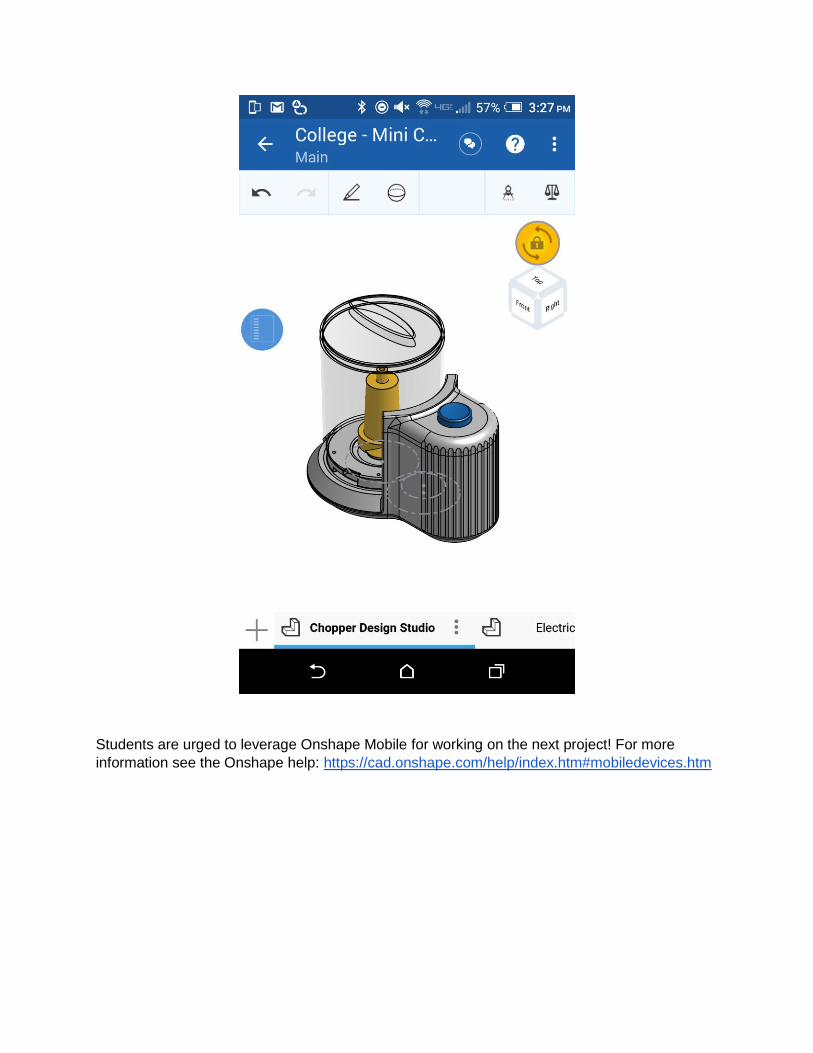
Students are urged to leverage Onshape Mobile for working on the next project! For more
information see the Onshape help: https://cad.onshape.com/help/index.htm#mobiledevices.htm