Webinar: Wellfield Operations and Technologies for ...
59
November 16, 2017 Presenters: Frank Terry (Smith Gardner, Inc.) Mark Hill (DTE Biomass Energy) Webinar: Wellfield Operations and Technologies for Upgrading Landfill Gas
Transcript of Webinar: Wellfield Operations and Technologies for ...
November 16, 2017
Presenters: Frank Terry (Smith Gardner, Inc.) Mark Hill (DTE Biomass Energy)
Webinar: Wellfield Operations and Technologies for
Upgrading Landfill Gas

Welcome
Webinar Agenda
LFG Wellfield Operational Considerations for Pipeline Quality Gas or Vehicle Fuel Projects Frank Terry, Smith Gardner, Inc., contractor to U.S. EPA LMOP
Technologies for Processing LFG into Pipeline Quality Gas or Vehicle Fuel Mark Hill, DTE Biomass Energy
Questions and Answers
Wrap-up & Participant Survey
Mention of any company, association, or product in this presentation is for information purposes only and does not constitute a recommendation of any such
company, association, or product, either express or implied, by the EPA.
LMOP Webinar | November 16, 2017 1

Webinar: Landfill Wellfield Design, Construction and
Operational Considerations for Upgraded LFG Projects November 16, 2017
Presenter: Frank Terry, Project Manager, Smith Gardner, Inc.,
(contractor to U.S. EPA LMOP)

Topics
• Background
• Collection System Design and Construction for High-Btu Wellfields
• High-Btu Wellfield Monitoring and Tuning
LMOP Webinar | November 16, 2017 1

Background
LMOP Webinar | November 16, 2017 2

Background: Low- vs. High-Btu projects Low- and Medium-Btu High-Btu
Heat Content (British thermal unit per standard cubic foot, Btu/scf)
350-550 950-1,000
Uses Boilers, engines, microturbines, turbines, kilns, combined heat and power, greenhouses, and other manufacturing processes that require fuel
Pipeline injection, vehicle fuel (Compressed Natural Gas ([CNG], Liquefied Natural Gas [LNG])
Number of Operational Projects*
483 – electricity 121 – non-Electricity
38 – pipeline injection 5 onsite CNG 1 onsite LNG
First Project Installation*
1974 (Sheldon Arleta, CA) [Demonstration Project]
1975 (Palos Verdes, CA)
Gas Treatment Moisture and contaminant removal (as needed)
Moisture, contaminant and CO2 removal
* These data are from LMOP’s Landfill and Landfill Gas Energy Database as of November 2017LMOP Webinar | November 16, 2017 3
Collection System Design and
Construction for High-Btu Wellfields
LMOP Webinar | November 16, 2017 4

Typical Gas Collection System Components
• Vertical Wells
• Horizontal Collectors
• Leachate Riser Tie-ins
• Header and Lateral Piping
• Piping Components
LMOP Webinar | November 16, 2017 5

Vertical Wells
• Low impact on landfill operations during construction
• Proven performance and lifespan
• Can be tailored to optimize high-Btu production via: Increased well density Bore depth Solid casing depth Location Bore seal integrity and placement Well boots
LMOP Webinar | November 16, 2017 6

Horizontal Collectors
• Inexpensive construction: no specialized equipment
• Effective in supplementing production but also subject to poor reliability, shorter lifespan and intermittent performance due to: Liquid blockage Differential settlement Pipe collapse or pinching Premature use
LMOP Webinar | November 16, 2017 7

Leachate Riser Tie-ins
• Usually can be easily connected to the GCCS
• Typically high flow rates, but notorious for oxygen leaks
• Effective in supplementing production, but also subject to poor reliability and intermittent performance due to: High leachate levels Pump failure Transducer malfunction
LMOP Webinar | November 16, 2017 8

Lateral and Header Piping
• Construction quality matters
Leaks may not be noticeable immediately after installation
Poor construction technique will eventually be revealed under high-Btu extraction conditions
• High Density Polyethylene (HDPE) piping is preferred over polyvinyl chloride (PVC)
Joining and fittings preferences, where possible:
Butt fusion joining is preferred over electrofusion
Molded fittings preferred over fabricated fittings
LMOP Webinar | November 16, 2017 9

Other Piping Components
Control Valves: More is better
Sample Port Risers: Placement for easy access
Condensate traps, sumps, and pump stations
Minimize penetrations
Utilize flanged or threaded connections wherever possible in place of rubber slip couplings
LMOP Webinar | November 16, 2017 10

Typical Problematic Areas for Potential Air Leaks
Sumps
Wellheads
LMOP Webinar | November 16, 2017 11

Pipe Fitting Selection for High-Btu Wellfield Applications
Molded Fitting Fabricated Fitting
LMOP Webinar | November 16, 2017 12

Minimize Potential Air Leaks During Construction
Fabricated fittings will be under stress from differential settlement
LMOP Webinar | November 16, 2017 13

High-Btu Wellfield Monitoring and Tuning
LMOP Webinar | November 16, 2017 14

High-Btu Wellfield Tuning Considerations
• LFG Generation
•Monitoring Objectives
•Analyzers
LMOP Webinar | November 16, 2017 15
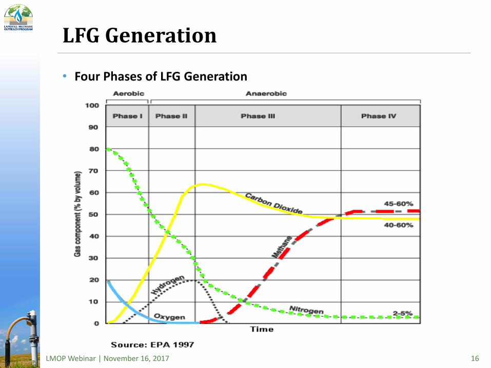
LFG Generation
• Four Phases of LFG Generation
LMOP Webinar | November 16, 2017 16

Inlet Gas Quality: Medium-Btu vs. High-Btu
LMOP Webinar | November 16, 2017 17

Monitoring Objectives for High-Btu* • Define and understand production goals and compliance
requirements Monthly NSPS minimum for compliance
Bi-monthly recommended for production
• Define and categorize collection zones
Identify problematic or sensitive areas
• Determine baseline tuning frequency to maintain consistency Increase monitoring focus where necessary
• Establish call out schedules and troubleshooting procedures to minimize downtime
* Monitoring requirements for a high-Btu project often differ from regulatory monitoring requirements. You are responsible for compliance with applicable regulations.
LMOP Webinar | November 16, 2017 18

Options: LFG Analyzers
Landtec GEM 5000 Elkins Envision
LMOP Webinar | November 16, 2017 19

Options: Analyzers
Gas Chromatograph (e.g., Agilent Micro GC 3000)
LMOP Webinar | November 16, 2017 20
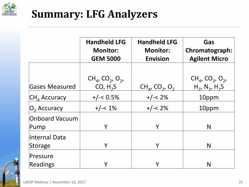
Summary: LFG Analyzers
Handheld LFG Handheld LFG Gas Monitor: Monitor: Chromatograph:
GEM 5000 Envision Agilent Micro
CH4, CO2, O2, CH4, CO2, O2, Gases Measured CO, H2S CH4, CO2, O2 H2, N2, H2S CH4 Accuracy +/-< 0.5% +/-< 2% 10ppm O2 Accuracy +/-< 1% +/-< 2% 10ppm Onboard Vacuum Pump Y Y N Internal Data Storage Y Y N Pressure Readings Y Y N
LMOP Webinar | November 16, 2017 21
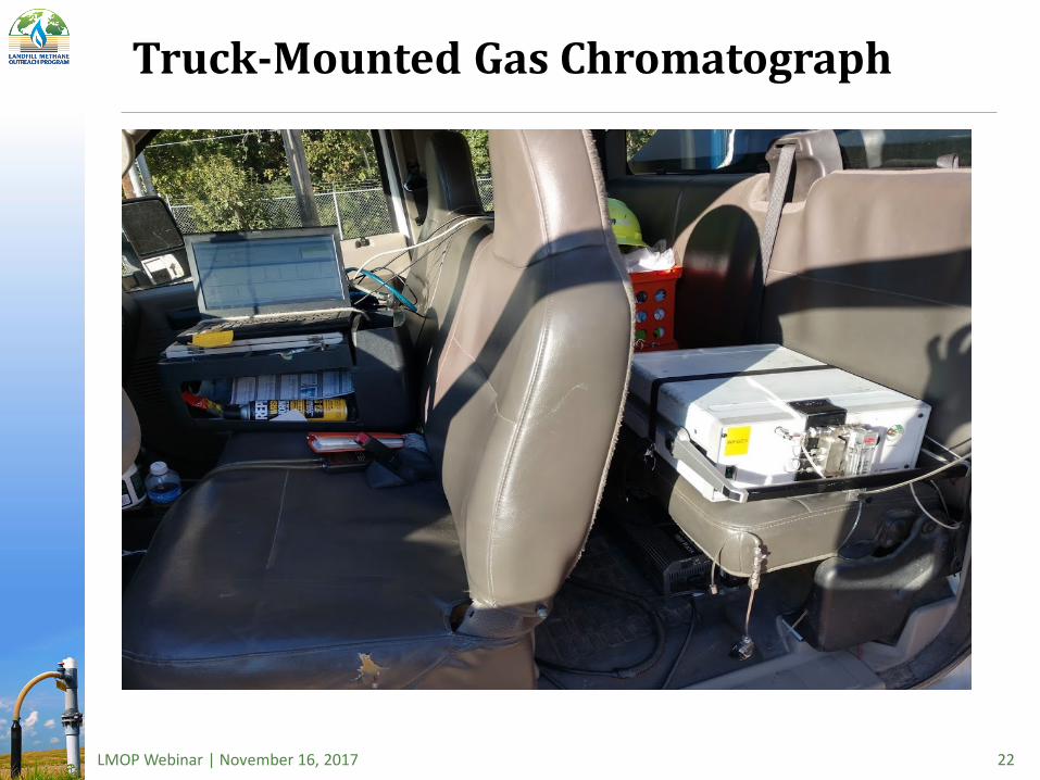
Truck-Mounted Gas Chromatograph
LMOP Webinar | November 16, 2017 22
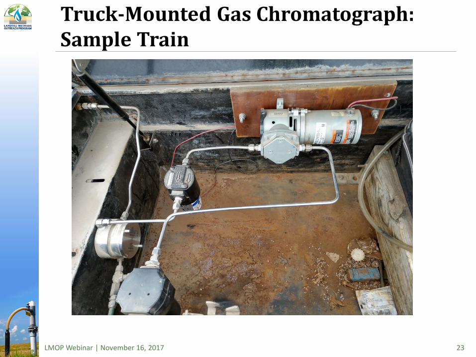
Truck-Mounted Gas Chromatograph: Sample Train
LMOP Webinar | November 16, 2017 23

Conclusion
• Understand the various phases of LFG generation
• Define and balance compliance and production goals
• Develop and apply definitive monitoring objectives based on process plant parameters
• Adjust wellfield design, construction and O&M standards to minimize air intrusion
• Engage and educate equipment operators on their role in high-Btu LFG wellfield management
• Invest in your wellfield technical staff
LMOP Webinar | November 16, 2017 24

Thank you for participating If you have any questions, please contact LMOP at
[email protected] or through our website at
https://www.epa.gov/lmop/forms/contact-us-about-landfill-methane-outreach-program
LMOP Webinar | November 16, 2017 25

Upgrading Landfill Gas to Pipeline Quality Renewable Natural GasEPA – LMOP Webinar
Mark R. Hill – Vice President of OperationsNovember 16, 2017

DTE Biomass Energy is a full scope developer that owns or operates 19 landfill gas to energy projects, including five pipeline-quality (renewable natural gas) facilities
2
Westside (2001) RNG project Other LFGTE project
(Fresh Kills (early 1980’s)
Owned by Dept. of Sanitation NYC)
Fort Bend (2014) Seabreeze (Q1 ‘18) Pinnacle (2002)

Agenda
3
Value drivers in the market today
Choosing the right technology
Getting the gas into a vehicle
Problems to avoid

With lower natural gas prices and higher priced environmental attributes, getting RNG into a highway vehicle is critical
4
$-
$5.00
$10.00
$15.00
$20.00
$25.00
$30.00
$35.00
$40.00
Henry Hub Natural Gas D3 RIN Pricing LCFS Pricing
D3 RIN - generated when RNG is used in highway vehicle
LCFS - RNG used in CA
Natural Gas Pricing
Total value stream can
be over $40/MMBtu
but is variable

Producing renewable natural gas (RNG) from landfill gas is capital intensive and has significant operating expenses …securing the right revenue stream is key.
5
Historic Approach
Long Term Off-Take
Do-it-yourself RINs
Deliver to a CNG Vehicle via Pipeline
Des
crip
tion Purify gas to pipeline
spec, sell into pipeline, receive NG index pricing
Purify gas to pipeline spec, sell at fixed price to customer
Purify gas, compress to 3500 PSI, and put into CNG highway vehicle
Purify gas to pipeline quality, put in pipeline, deliver to CNG fueling station, fuel highway vehicle
Valu
e St
ream
s Index pricing based on market natural gas rates
Set price per MMBtu for several years
If you have a CNG vehicle fleet, RNG would offset natural gas costs and RINs would be generated
Natural gas value, RIN value, and LCFS (if vehicles fueled are in California)
Pros
Con
s
No RIN verification needed
Steady prices typically at a premium to long term natural gas prices
RINs generated with no “middleman” costs
No pipeline needed, “easier” spec
Multiple value streams
Not captive to local CNG highway vehicle demand
Natural gas prices are currently very low
Requires pipeline
May be at a discount to spot market RIN pricing
Requires pipeline
Requires gas storage and large on-highway vehicle fleet to fully utilize RNGVariable pricing
Variable pricing
Requires pipeline
Possible broker fees

Agenda
6
Value drivers in the market today
Choosing the right technology
Getting the gas into a vehicle
Problems to avoid

Ahem….The Disclaimer
• This presentation is not meant to favor one technology or a vendor
• Data presented are what I have seen as ”typical”; there are several companies making improvements to the systems described that may yield better results than shown
• Every plant, pipeline specification, and landfill is different and the configurations may need to be different from what is shown in this presentation
• Make sure to do your due diligence on any new project
7
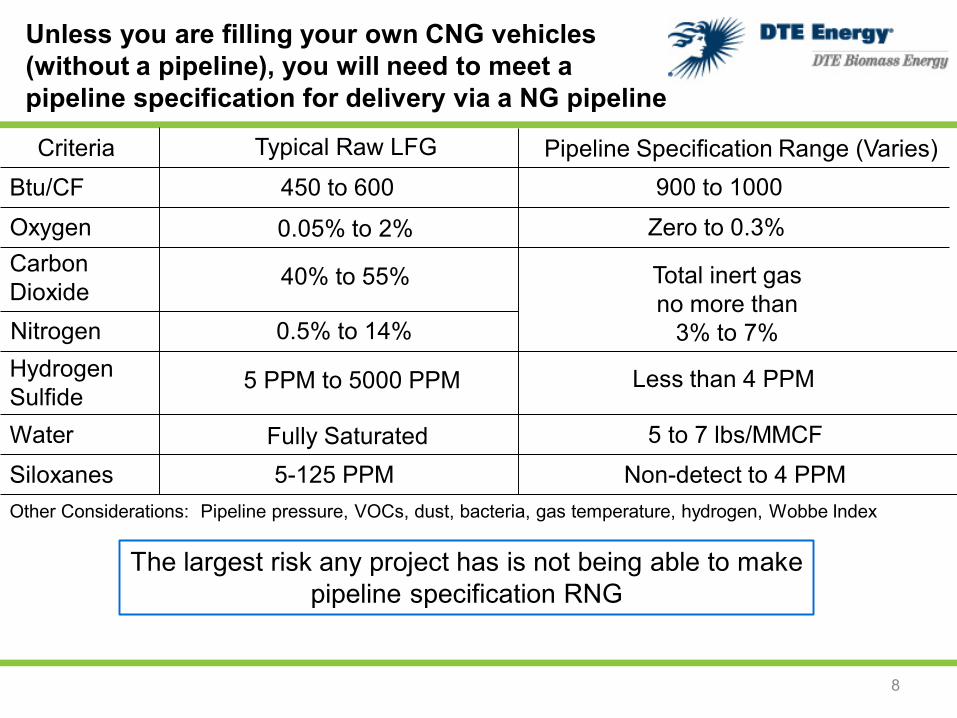
Unless you are filling your own CNG vehicles (without a pipeline), you will need to meet a pipeline specification for delivery via a NG pipeline
8
Btu/CFCriteria Typical Raw LFG Pipeline Specification Range (Varies)
450 to 600 900 to 1000Oxygen 0.05% to 2% Zero to 0.3%Carbon Dioxide 40% to 55% Total inert gas
no more than 3% to 7%Nitrogen 0.5% to 14%
Hydrogen Sulfide
5 PPM to 5000 PPM Less than 4 PPM
Water Fully Saturated 5 to 7 lbs/MMCFSiloxanes 5-125 PPM Non-detect to 4 PPMOther Considerations: Pipeline pressure, VOCs, dust, bacteria, gas temperature, hydrogen, Wobbe Index
The largest risk any project has is not being able to make pipeline specification RNG
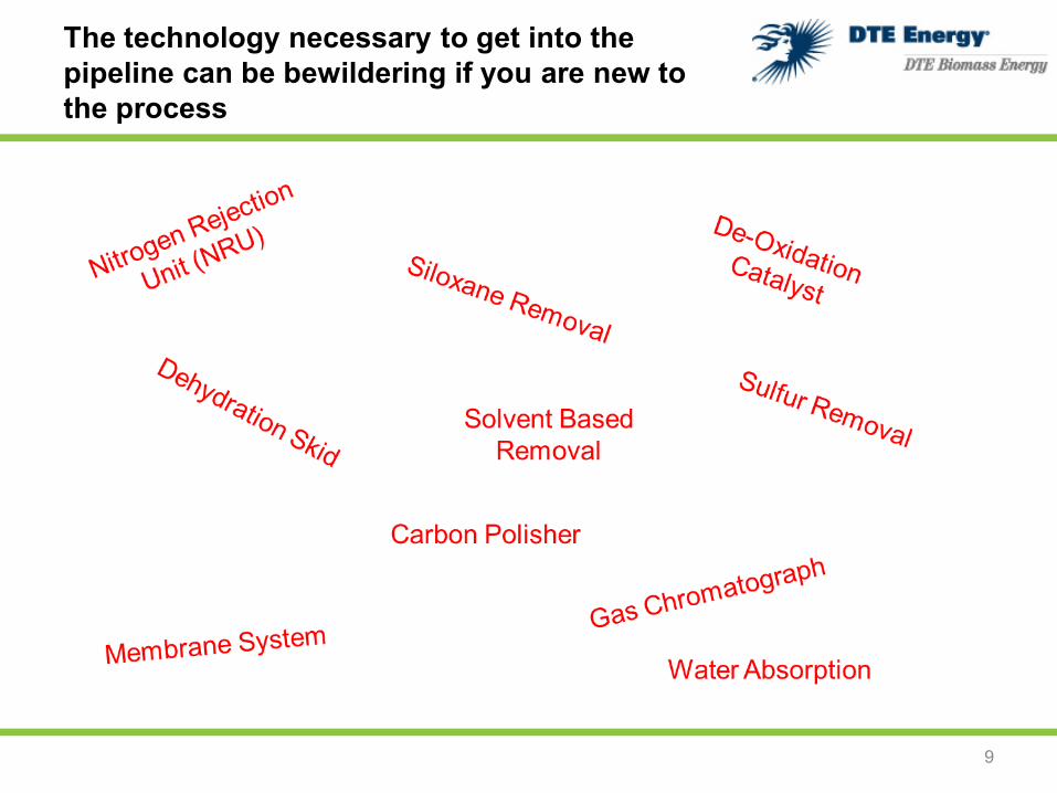
The technology necessary to get into the pipeline can be bewildering if you are new to the process
9

Let’s start with the largest component removed –carbon dioxide. There are four “mainstream” competing technologies used to remove CO2
10
Membrane System
Polymer membranes with tiny “tunnels” that separate carbon dioxide from methane
Solvent System
Vessels filled with liquid that absorbs carbon dioxide and lets methane pass through; the solvent is regenerated by releasing the carbon dioxide
Pressure Swing Absorption (PSA)
Uses an absorbent material (molecular sieve) that separates the carbon dioxide from the methane then releases it when the pressure in the vessel changes
Water Absorption
Uses large amounts of water to absorb the carbon dioxide, letting the methane pass through

Typical Pipeline-Quality Membrane System
11

Example of a membrane plant
12

Non-pipeline quality vehicle fueling station using membrane technology
13
• Uses membrane technology
• Activated carbon used for siloxane removal instead of regenerative system
• Typically a one pass membrane system – more methane slippage
• Looser spec needed than for pipeline quality gas
• Requires a dedicated fleet of vehicles (which is hard to do)

Typical Solvent System Flow Diagram
14

Example of a Solvent Plant
15

Pressure Swing Absorption uses media to absorb and release gases. This process is more energy intensive than others
16
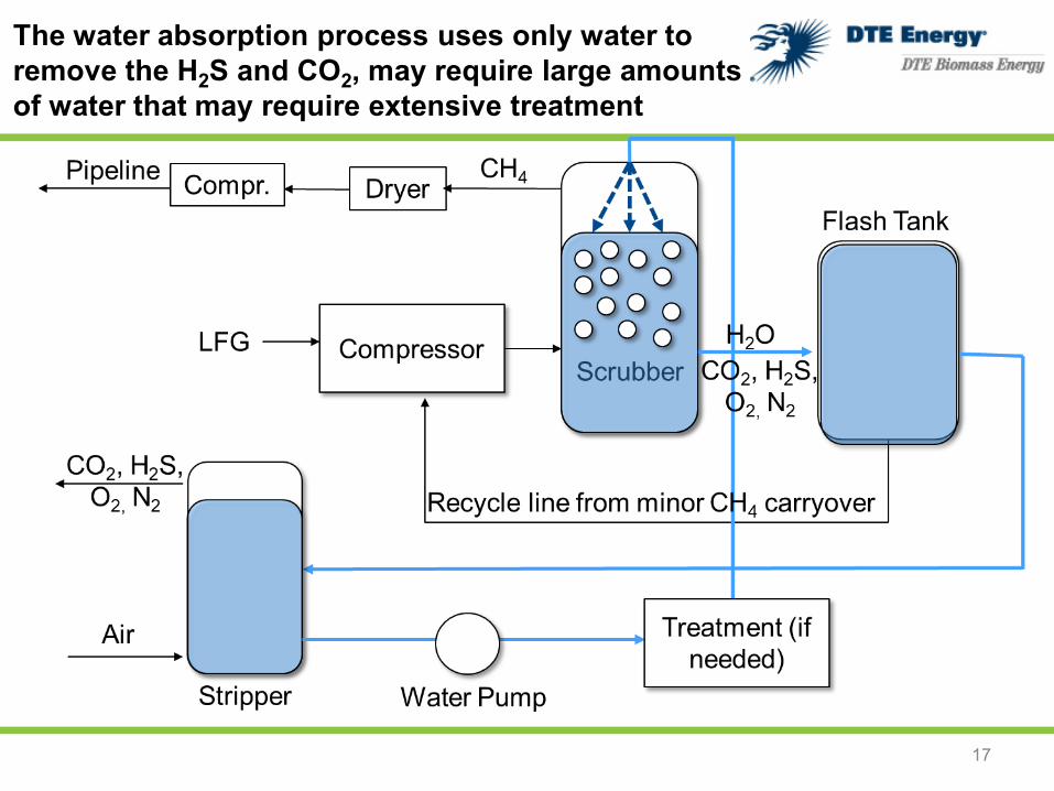
The water absorption process uses only water to remove the H2S and CO2, may require large amounts of water that may require extensive treatment
17

There is no one correct answer on which technology to choose – it is dependent upon your LFG gas quality, pipeline specification, and long term plans
18
Tech Advantages Disadvantages
Mem
bran
eSo
lven
tPS
AW
ater
Ab
sorp
tion
• Simple “black box” technology with few moving parts other than compressors
• Removes some O2 – may help meet looser O2 specs• Historically good on-stream rates• Easily expandable• Smaller plant footprint
• Beholden to membrane manufacturer• 94% methane recovery• Activated carbon and H2S removal are expensive• Membranes do not “like” contaminants• Separate siloxane removal system needed
• Plant components are widely used in the oil/gas industry – spares are readily available
• 98 to 99% methane recovery• Historically good on-stream rates• Typical solvent removes siloxanes and VOCs
without needing disposable media
• Expansion may require new towers and compressors• Typical solvent does not remove any O2 or N2• Larger/taller plant footprint• Does not remove any O2• Because of low CH4 loss, additional fuel needed for TOX• More things to break (pumps, vacuum blowers, etc.)
• May remove other components of the gas stream, including some N2 and O2
• Few moving parts other than valves and compressors
• ~95% methane recovery• Pressurization/depressurization/re-pressurization process
is energy intensive• Leaky valves can create serious issues
• Simple process that just uses water• ~96% methane recovery• Removes some N2 and O2
• Uses a lot of water – treatment of water may be costly and complicated
• Large foot print with large vessels• Can only handle a certain level of N2 and O2• More moving parts (pumps, valves, etc.)

Siloxane removal is needed for membrane systems and potentially others. Regenerative systems are usually paired with an activated carbon polisher
19
Regenerative
• High rate of siloxane removal if proper sizing and media is selected; however, it is not 99.9% effective - which is sometimes necessary to achieve
• One vessel in service while others are being purged using LFG and/or air; often these tail gases require a flare/TOX
• Additional electric load and compression needed, as is gas drying
• System needs to be tuned and tested for siloxane removal effectiveness
Non-regenerative
Activated Carbon• Highly effective at removing nearly everything – including
siloxanes• Expensive if the sole means for removing siloxanes• Other impurities, such as H2S, can reduce effective life of
activated carbon that is targeting siloxane• Free liquids can reduce effectiveness of media

Hydrogen Sulfide (H2S) Removal
20
Non-NRU plants (no O2 in inlet gas)
Sulfur removal vessels at a solvent plant
Typically use Sulfatrap, Sulfatreat, activated carbon or similar disposable media
Can be very expensive if inlet H2S levels are high–factor this into economics of a project
Ensure you have a back-up vessel so that you are able to meet pipeline quality if media becomes exhausted
NRU Plants (O2 in inlet gas)
Can use any of the removal systems shown with non-NRU plants
May also explore using a less expensive iron-sponge media that is mounted on wood chips – this system requires low levels of oxygen, which would not be compatible with a non-NRU plant
Iron sponge media being loaded into vessels

An oxygen removal system is necessary if you have to hit a tight oxygen specification
21
Typical system uses palladium or platinum catalyst at high temperatures
The oxygen and methane molecules react on the catalyst, form water, and strip out the oxygen from the gas stream
Dryer needed to remove water created by the process
Necessary at some sites with tight pipeline specifications, but expensive and energy intensive

Nitrogen Removal Unit (NRU)
Storage bladder for methane coming off of NRU
Typically uses pressure swing absorption technology to absorb CH4 and let N2 pass through and be vented/treated (other technologies than PSA exist)
Expensive to build and very energy intensive
Designed around a specific nitrogen amount – if that amount is exceeded the plant capacity rapidly drops
Methane percent yield drops to upper 80s due to methane slippage in NRU
22
DTE Biomass Energy prefers to prevent nitrogen intrusion in the wellfield rather than go through the expense of removing it at the plant; however, if this is not
possible, an NRU will be necessary to meet tight pipeline specifications

Hitting a “tight” Btu/CF pipeline specification
If your plant is falling short of a high Btu/CF pipeline specification, there are a few things you can do:
1) Fix the wellfield! 90% of cases where a plant fails to meet the Btu specification emanate from atmospheric intrusion into the gas collection system. Having a well-run, low atmospheric intrusion wellfield is the most important part of a successful RNG project.
2) Blend natural gas at the interconnect (for a fee, and if allowed). Separate metering required to keep renewable and non-renewable accounted for –check with RIN verifier. Alternatively, blend propane (again, separate metering required – check with RIN verifier).
3) Expensive equipment (e.g., amine unit or NRU) to remove remaining carbon dioxide or nitrogen
23
Agenda
24
Value drivers in the market today
Choosing the right technology
Getting the gas into a vehicle
Problems to avoid

The majority of RNG is shipped via pipeline to vehicle fueling stations
25
LFG to RNG Plant
Dedicated Pipeline
Interconnect with local NG pipeline
CNG Filling Station
US NG Pipeline System

Not all landfills are near a pipeline. There are virtual pipeline alternatives, but they require more operating expenses and logistics
26
LFG to RNG Plant
CNG Tanker
Drive CNG tanker directly to CNG fueling station
Drive CNG tanker to local interconnect

Agenda
27
Value drivers in the market today
Choosing the right technology
Getting the gas into a vehicle
Problems to avoid

Producing pipeline quality gas from landfill gas is really easy to mess up…
“Learn from past mistakes – preferably someone else's” - Fred Brooks (IBM Computer Architect)
28
Most projects that fail, fail due to poor quality of gas from the wellfield• NRUs are not “bulletproof” and require moderate levels of nitrogen• Oxygen intrusion and poor methane quality will make RNG production near
impossible regardless of technology used• Developers frequently want control of the wellfield to ensure their tens of
millions of dollars spent on the plant are not wasted. With the right developer, this can lead to continued NSPS compliance, lower electric usage (no NRU needed), and higher royalty payments (a larger pie to share).
Hire the right operations team• Typically a very small team that has to be good at everything• Do not be “cheap” with poor quality wellfield technicians – they are the most
important component to a successful project• Ensure you have an instrumentation and controls tech and a compressor tech• Manager needs to be multifaceted – environmental compliance, knowledge of
commercial contracts, and knowledge of both plant and wellfield are key

Pitfalls to avoid (Continued)
29
Metering LFG is very difficult• Must take into account specific gravity changes, moisture content, heat, pressure,
etc.• Failure to properly place, program, calibrate, and record flow data can jeopardize
creation of RINs and LCFS
Build redundancy around media vessels and be ready for more pressure loss• Activated carbon and sulfur removal media may be exhausted prematurely, make
sure to have back-up vessels ready• As media ages, differential pressure frequently increase – build in additional
compression capacity to take this higher differential pressure into account
Do not undersize the NRU (if needed)• If the NRU is built for 4% nitrogen and you experience 14% nitrogen, plant
capacity could be cut in half

Be ready for a very expensive capital investment
Like a new car, the base model looks like a bargain, but by the time you get all the options you need, costs can increase by 50%
PlantsBase plant: Ten(s) of millions in capital – very dependent on size of plantNRU: Millions of dollarsDe-Oxidation Unit: Hundreds of Thousands to $1.5 Million
WellfieldDepends on the site, but could cost $1 million or more to convert a medium-Btu wellfield to a high-Btu wellfield
PipelineInterconnects in the hundreds of thousands of dollars (or even millions). Installed pipeline can be near $1 million per mile. Right of ways can delay projects by over a year.
30
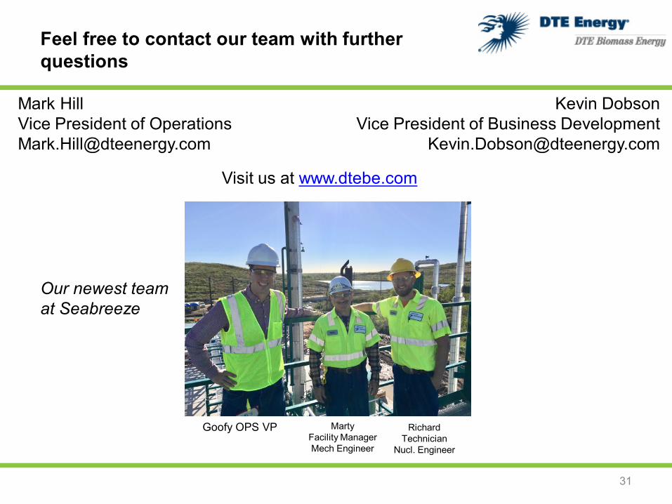
Feel free to contact our team with further questions
31
Mark HillVice President of [email protected]
Kevin DobsonVice President of Business Development
Visit us at www.dtebe.com
Our newest team at Seabreeze
Goofy OPS VP Marty Facility ManagerMech Engineer
RichardTechnician
Nucl. Engineer