€¦ · Web viewThe types of ingredients within a coating may be obtained from Material Safety...
67
PAINTING BASICS AND EMISSION CALCULATIONS FOR TCEQ AIR QUALITY PERMIT APPLICATIONS DECEMBER 13, 2005 (UPDATED OCTOBER 11, 2006) TEXAS COMMISSION ON ENVIRONMENTAL QUALITY Protecting Texas by Reducing And Preventing Pollution Presented by: Mike Coldiron, P.E. and Eddie Mack, P.E. Texas Commission on Environmental Quality
Transcript of €¦ · Web viewThe types of ingredients within a coating may be obtained from Material Safety...

PAINTING BASICS AND EMISSION CALCULATIONS

FOR TCEQ AIR QUALITY PERMIT APPLICATIONS
DECEMBER 13, 2005 (UPDATED OCTOBER 11, 2006)
TEXAS COMMISSION ON ENVIRONMENTAL QUALITY


Protecting Texas by Reducing
And
Preventing Pollution
Presented by:

Mike Coldiron, P.E. and Eddie Mack, P.E.Texas Commission on Environmental Quality
Austin, Texas
INTRODUCTION
Surface coated products are all around, and coatings are applied to many types of industrial
equipment and consumer products to provide decorative and protective finishes as well as
functional uses such as adhesives. The application of these finishes, while improving product
performance or extending product life, releases significant emissions of solvents and solids into 1

the environment. As such, the EPA, state, and local authorities have promulgated regulations
that limit coating solvent content, emission rates, solvent, and solid species limits to reduce the
formation of ground level ozone and to protect public health from unhealthy levels of exposure
to solids and solvents. In addition to the state and federal industry-wide rules, all facilities in
Texas that emit air contaminants into the air of the State of Texas must obtain a preconstruction
2

permit authorization before construction of the facility is begun, as required by Title 30 Texas
Administrative Code (30 TAC) §116.110.
There are a number of methods to demonstrate compliance with the emission limits in
regulations or to estimate emissions for preconstruction authorizations such as AP-42 emission
factors, stack sampling, coating solvent testing, or the use of continuous emission monitors.
3
Emission factors lack accuracy and even applicability to a specific type of process or product
type. Stack sampling and continuous monitors are expensive and lack the ability to demonstrate
compliance with coating solvent content limits. Monitors also tell the facility about a problem or
potential violation only after it has occurred. Coating solvent content testing may be used both
before and after the application of the coating, but this can be expensive and inconvenient.
4

Emission calculations effectively deal with many of these problems and reduce compliance
demonstration costs, prevent violations, allow the facility to set appropriate emission limits
during permitting, and provide important cost and process information to facility management.
However, the accuracy of the calculations is dependent on the quality of the data used in the
calculations, and the level of effort required to produce the results is dependent on the how well
the data is organized. The purpose of this paper is to provide environmental professionals with
5

the necessary background to collect usable data, organize the data, and use the data to
successfully complete emission calculations for a number of types of emission standards and
limits.
REASONS TO CALCULATE EMISSIONS FROM SURFACE COATING SOURCES
6

Traditionally, calculations were carried out after the fact in response to regulatory requirements
and were looked upon as a burden to the facility. However, emission calculations provide both
predictive and retrospective evaluations of surface coating facility operations from an
environmental and business perspective. Rather than being viewed by management as an
expense, emission calculations can provide opportunities for process improvement and
reductions in operating costs.
7

The retrospective use of emission calculations is primarily for demonstration of compliance with
regulatory requirements such as the following:
Federal New Source Performance Standards (NSPS) under Title 40 Code of Federal
Regulations, Part 60 (40 CFR 60);
8

Federal National Emission Standards for Hazardous Air Pollutants (NESHAPs) under
40 CFR 63;
State Reasonably Available Control Technology (RACT) requirements;
State and federal construction permits; and
State and federal operating permits under 40 CFR 70;
9

Retrospective uses also include the determination of emissions for historical purposes such as the
following:
Emission Inventories;
Calculation of Emission Fees; and
10
The quantity of emissions released during emissions events (formerly known as
‘upsets’).
Prospective uses allow the facility to ensure compliance before the fact in areas such as the
following:
Air quality construction permit applications;
11

Determination of applicability of State and federal permit programs;
Evaluation of new processes and products to determine if they will be compliant with
State and federal rules before introduction;
Monitor process performance and reduce production costs through improvements in
transfer efficiency and increasing coatings solids content;
12

Determination of optimal operating points for volatile organic compound (VOC) and
particulate matter (PM) emission controls;
Production scheduling to maintain compliance with RACT, NSPS, and NESHAP
rules that allow for averaging to comply with the standard;
13

Well-organized and complete emission calculations in both modes will result in greater
confidence in facility management of the ability of the facility to meet applicable requirements.
DEFINITIONS
14

Emission calculations are more easily understood if the exact wording of regulatory definitions
and their limitations are understood. What the definitions do not say is as important as what they
do say as well as how they are related to each other.
Coating – A material applied onto or impregnated into a substrate for protective,
decorative or functional purposes. Such materials include, but are not limited to, paints,
15

varnishes sealants, adhesives, thinners, diluents, inks, maskants, and temporary protective
coatings.
Coating application system – Devices or equipment designed for the purpose of
applying a coating material to a surface. The devices may include, but are not limited to,
brushes, sprayers, flow coaters, dip tanks, rollers, knife coaters, and extrusion coaters.
16
Coating line – An operation consisting of a series of one or more coating application
systems and including associated flashoff area(s), drying area(s), and oven(s) wherein a
surface coating is applied, dried, or cured.
Coating solids (or solids) – The part of the coating that remains after the coating is dried
or cured.
17

Capture efficiency – The amount of VOC collected by a capture system that is expressed
as a percentage derived from the weight per unit time of VOC entering a capture system
and delivered to a control device divided by the weight per unit time of total VOC
generated by a source of VOC.
18

Exempt solvent – Those carbon compounds or mixtures of carbon compounds that have
been excluded from the definition of volatile organic compound.
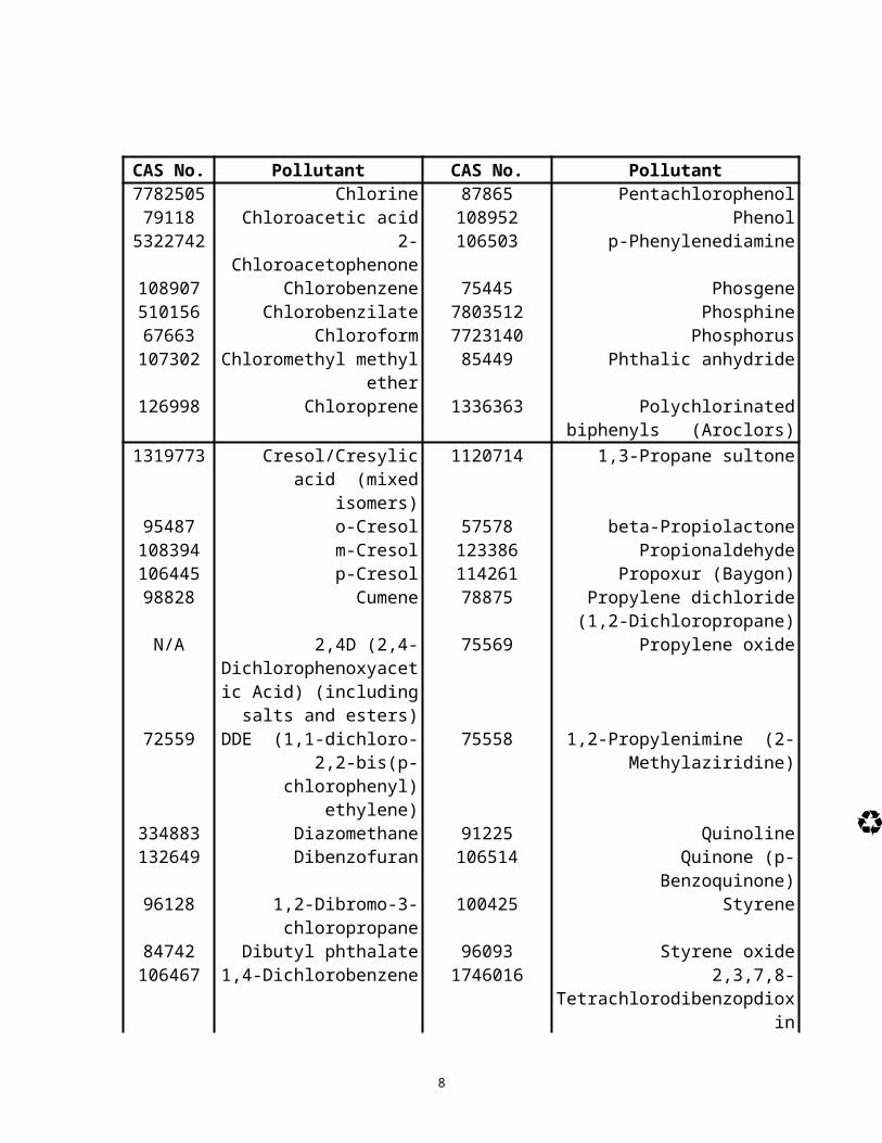
Hazardous air pollutant – Means any air pollutant listed in or pursuant to section
112(b) of the [Federal Clean Air] Act. Hazardous air pollutants (HAPs) are as follows:
19

CAS No. Pollutant CAS No. Pollutant75070 Acetaldehyde 110543 Hexane60355 Acetamide 302012 Hydrazine 75058 Acetonitrile 7647010 Hydrochloric acid (Hydrogen
Chloride)98862 Acetophenone 7664393 Hydrogen fluoride (Hydrofluoric
acid)539632 Acetylaminofluorene 123319 Hydroquinone107028 Acrolein 78591 Isophorone
20

CAS No. Pollutant CAS No. Pollutant79061 Acrylamide 108316 Maleic anhydride79107 Acrylic acid 67561 Methanol107051 Acrylonitrile 72435 Methoxychlor 107051 Allyl chloride 74839 Methyl bromide
(Bromomethane)926714 4-Aminobiphenyl 74873 Methyl chloride (Chloromethane) 62533 Aniline 71556 Methyl chloroform
(1,1,1-Trichloroethane) 21

CAS No. Pollutant CAS No. Pollutant90040 o-Anisidine 60344 Methylhydrazine
1332214 Asbestos 78933 Methyl ethyl ketone (Removed 12/19/05, 70 FR 75047)
71432 Benzene (including benzene from gasoline)
74884 Methyl iodide (Iodomethane)
92875 Benzidine 108101 Methyl isobutyl ketone (Hexone)98077 Benzotrichloride 624839 Methyl isocyanate 100447 Benzyl chloride 80626 Methyl methacrylate
22

CAS No. Pollutant CAS No. Pollutant92524 Biphenyl 1634044 Methyl tert-butyl ether117817 Bis(2-ethylhexyl)phthalate
(DEHP)101144 4,4'-Methylenebis(2-
chloroaniline) 542881 Bis(chloromethyl) ether 75092 Methylene chloride
(Dichloromethane)75252 Bromoform 101688 4,4'-Methylenediphenyl
diisocyanate (MDI)106990 1,3-Butadiene 101779 4,4'-Methylenedianiline
23

CAS No. Pollutant CAS No. Pollutant156627 Calcium cyanamide 91203 Naphthalene 105602 Caprolactam (Removed
6/18/96, 61 FR 30816)98953 Nitrobenzene
133062 Captan 92933 4-Nitrobiphenyl63252 Carbaryl 100027 4-Nitrophenol 75150 Carbon disulfide 79469 2-Nitropropane56235 Carbon tetrachloride 684935 N-Nitroso-N-methylurea463581 Carbonyl sulfide 62759 N-Nitrosodimethylamine
24
CAS No. Pollutant CAS No. Pollutant120809 Catechol 59892 N-Nitrosomorpholine133904 Chloramben 56382 Parathion57749 Chlordane 82688 Pentachloronitrobenzene
(Quintobenzene)7782505 Chlorine 87865 Pentachlorophenol 79118 Chloroacetic acid 108952 Phenol
5322742 2-Chloroacetophenone 106503 p-Phenylenediamine108907 Chlorobenzene 75445 Phosgene
25

CAS No. Pollutant CAS No. Pollutant510156 Chlorobenzilate 7803512 Phosphine 67663 Chloroform 7723140 Phosphorus107302 Chloromethyl methyl ether 85449 Phthalic anhydride126998 Chloroprene 1336363 Polychlorinated biphenyls
(Aroclors)1319773 Cresol/Cresylic acid (mixed
isomers)1120714 1,3-Propane sultone
95487 o-Cresol 57578 beta-Propiolactone26

CAS No. Pollutant CAS No. Pollutant108394 m-Cresol 123386 Propionaldehyde 106445 p-Cresol 114261 Propoxur (Baygon) 98828 Cumene 78875 Propylene dichloride (1,2-
Dichloropropane)N/A 2,4D (2,4-
Dichlorophenoxyacetic Acid) (including salts and
esters)
75569 Propylene oxide
27

CAS No. Pollutant CAS No. Pollutant72559 DDE (1,1-dichloro-2,2-
bis(p-chlorophenyl) ethylene)
75558 1,2-Propylenimine (2-Methylaziridine)
334883 Diazomethane 91225 Quinoline132649 Dibenzofuran 106514 Quinone (p-Benzoquinone)96128 1,2-Dibromo-3-
chloropropane 100425 Styrene
84742 Dibutyl phthalate 96093 Styrene oxide28
CAS No. Pollutant CAS No. Pollutant106467 1,4-Dichlorobenzene 1746016 2,3,7,8-
Tetrachlorodibenzopdioxin91941 3,3'-Dichlorobenzidine 79345 1,1,2,2-Tetrachloroethane111444 Dichloroethyl ether (Bis[2-
chloroethyl]ether)127184 Tetrachloroethylene
(Perchloroethylene) 542756 1,3-Dichloropropene 7550450 Titanium tetrachloride62737 Dichlorvos 108883 Toluene111422 Diethanolamine 95807 Toluene-2,4-diamine
29
CAS No. Pollutant CAS No. Pollutant6467 Diethyl sulfate 584849 2,4-Toluene diisocyanate
119904 3,3'-Dimethoxybenzidine 95534 o-Toluidine 60117 4-
Dimethylaminoazobenzene8001352 Toxaphene (chlorinated
camphene)121697 N,N-Dimethylaniline 120821 1,2,4-Trichlorobenzene119937 3,3'-Dimethylbenzidine 79005 1,1,2-Trichloroethane 79447 Dimethylcarbamoyl chloride 79016 Trichloroethylene 68122 N,N-Dimethylformamide 95954 2,4,5-Trichlorophenol
30

CAS No. Pollutant CAS No. Pollutant57147 1,1-Dimethylhydrazine 88062 2,4,6-Trichlorophenol 131113 Dimethyl phthalate 121448 Triethylamine 77781 Dimethyl sulfate 1582098 Trifluralin N/A 4,6-Dinitr-o-ocresol
(including salts)540841 2,2,4-Trimethylpentane
51285 2,4-Dinitrophenol 108054 Vinyl acetate 121142 2,4-Dinitrotoluene 593602 Vinyl bromide
31

CAS No. Pollutant CAS No. Pollutant123911 1,4-Dioxane (1,4-
Diethyleneoxide)75014 Vinyl chloride
122667 1,2-Diphenylhydrazine 75354 Vinylidene chloride (1,1Dichloroethylene)
106898 Epichlorohydrin (1-Chloro-2,3-epoxypropane)
1330207 Xylenes (mixed isomers)
106887 1,2-Epoxybutane 95476 o-Xylene 140885 Ethyl acrylate 108383 m-Xylene
32

CAS No. Pollutant CAS No. Pollutant100414 Ethylbenzene 106423 p-Xylene51796 Ethyl carbamate (Urethane) Antimony
Compounds Antimony Compounds
75003 75003 Ethyl chloride (Chloroethane)
Arsenic Compounds
Arsenic Compounds (inorganic including arsine)
106934 Ethylene dibromide (Dibromoethane)
Beryllium Compounds
Beryllium Compounds
107062 Ethylene dichloride (1,2- Cadmium Cadmium Compounds33
CAS No. Pollutant CAS No. PollutantDichloroethane) Compounds
107211 Ethylene glycol Chromium Compounds
Chromium Compounds
151564 Ethyleneimine (Aziridine) Cobalt Compounds
Cobalt Compounds
75218 Ethylene oxide Coke Oven Emissions
Coke Oven Emissions
96457 Ethylene thiourea Cyanide Cyanide Compounds1
34

CAS No. Pollutant CAS No. PollutantCompounds1
75343 Ethylidene dichloride (1,1-Dichloroethane)
Glycol ethers2 Glycol ethers2
50000 Formaldehyde Lead Compounds
Lead Compounds
76448 Heptachlor Manganese Compounds
Manganese Compounds
118741 Hexachlorobenzene Mercury Mercury Compounds35
CAS No. Pollutant CAS No. PollutantCompounds
87683 Hexachlorobutadiene Fine mineral fibers3
Fine mineral fibers3
N/A 1,2,3,4,5,6-Hexachlorocyclyhexane (all
stereo isomers, including lindane)
Nickel Compounds
Nickel Compounds
36
CAS No. Pollutant CAS No. Pollutant77474 Hexachlorocyclopentadiene Polycyclic
Organic Matter4 Polycyclic Organic Matter4
67721 Hexachloroethane Radionuclides (including
radon)5
Radionuclides (including radon)5
822060 Hexamethylene diisocyanate Selenium Compounds
Selenium Compounds
37
CAS No. Pollutant CAS No. Pollutant680319 Hexamethylphosphoramide
NOTE: For all listings above which contain the word “compounds” and for glycol ethers, the following applies: Unless otherwise specified, these listings are defined as including any unique chemical substance that contains the named chemical (i.e., antimony, arsenic, etc.) as part of that chemical's infrastructure.
38
1 X'CN where X = H' or any other group where a formal dissociation may occur. For example, KCN or Ca(CN)2
2 Includes mono- and di-ethers of ethylene glycol, diethylene glycol, and triethylene glycol R-(OCH2CH2)n-OR' where
39

n = 1, 2, or 3R = alkyl or aryl groupsR' = R, H, or groups which, when removed, yield glycol ethers with the structure: R-(OCH2CH)n-OH. Polymers are excluded from the glycol category.
Ethylene glycol monobutyl ether (EGBE) (2-Butoxyethanol) (CAS No. 111-76-2) was removed from the group of glycol ethers on 11/29/04 (69 FR 69320).
40
Surfactant alcohol ethoxylates and their derivatives (SAED) were removed from the group of glycol ethers on 8/2/00 (65 FR 47342).
3 Includes mineral fiber emissions from facilities manufacturing or processing glass, rock, or slag fibers (or other mineral derived fibers) of average diameter 1 micrometer or less.
41

4 Includes organic compounds with more than one benzene ring, and which have a boiling point greater than or equal to 100 º C.
5 A type of atom which spontaneously undergoes radioactive decay.
42

Particulate matter – Any material, except uncombined water, that exists as a solid or
liquid in the atmosphere or in a gas stream at standard conditions.
Transfer efficiency – The amount of coating solids deposited onto the surface or a part
of a product divided by the total amount of coating solids delivered to the coating
application system.
43

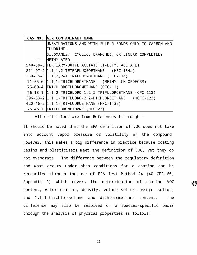
Volatile organic compound – any compound of carbon or mixture of carbon
compounds except the following:
CAS NO. AIR CONTAMINANT NAME67-64-1 ACETONE506-87-6 AMMONIUM CARBONATE124-38-9 CARBON DIOXIDE630-08-0 CARBON MONOXIDE
44

CAS NO. AIR CONTAMINANT NAME---- CARBONIC ACIDS-U
75-68-3 1-CHLORO-1,1-DIFLUOROETHANE (HCFC-142b)75-45-6 CHLORODIFLUOROMETHANE (HCFC-22)593-70-4 CHLOROFLUOROMETHANE (HCFC-31)1615-75-4 1-CHLORO-1-FLUOROETHANE (HCFC-151a)593-70-4 CHLOROFLUOROMETHANE (HCFC-31)76-15-3 CHLOROPENTAFLUOROETHANE (CFC-115)
45

CAS NO. AIR CONTAMINANT NAME2837-89-0 2-CHLORO-1,1,1,2-TETRAFLUOROETHANE (HCFC-124)
138495-42-8 1,1,1,2,3,4,4,5,5,5-DECAFLUOROPENTANE (HFC 43-10mee)75-71-8 DICHLORODIFLUOROMETHANE (CFC-12)
1717-00-6 1,1-DICHLORO-1-FLUOROETHANE (HCFC-141b)507-55-1 1,3-DICHLORO-1,1,2,2,3-PENTAFLUOROPROPANE (HCFC-225cb)422-56-0 3,3-DICHLORO-1,1,1,2,2-PENTAFLUOROPROPANE (HCFC-225ca)76-14-2 1,2-DICHLORO 1,1,2,2-TETRAFLUOROETHANE (CFC-114)
46

CAS NO. AIR CONTAMINANT NAME354-23-4 1,2-DICHLORO-1,1,2-TRIFLUOROETHANE (HCFC-123a) 75-37-6 1,1-DIFLUOROETHANE (HFC-152a)75-10-5 DIFLUOROMETHANE (HFC-32)
163702-08-72-(DIFLUOROMETHOXYMETHYL)-1,1,1,2,3,3,3-HEPTAFLUOROPROPANE ((CF3)2CFCF2OCH3)
74-84-0 ETHANE163702-06-5 2-(ETHOXYDIFLUOROMETHYL)-1,1,1,2,3,3,3-HEPTAFLUOROPROPANE
47

CAS NO. AIR CONTAMINANT NAME((CF3)2CFCF2OC2H5)
297730-93-9
3-ETHOXY-1,1,1,2,3,4,4,5,5,6,6,6-DODECAFLUORO-2-(TRIFLUOROMETHYL) HEXANE(HFE-7500, HFE-s702, T7145, and L-15381)
163702-05-4 1-ETHOXY-1,1,2,2,3,3,4,4,4-NONAFLUOROBUTANE (HFE-7200)353-36-6 ETHYLFLUORIDE (HFC-161)375-03-1 1,1,1,2,2,3,3-HEPTAFLUORO-3-METHOXYPROPANE (HFE-7000)
48

CAS NO. AIR CONTAMINANT NAME431-89-0 1,1,1,2,3,3,3-HEPTAFLUOROPROPANE (HFC-227ea)431-63-0 1,1,1,2,3,3-HEXAFLUOROPROPANE (HFC-236ea)690-39-1 1,1,1,3,3,3-HEXAFLUOROPROPANE (HFC-236fa)
---- METALLIC CARBIDES-U---- METALLIC CARBONATES-U
74-82-8 METHANE79-20-9 METHYL ACETATE
49

CAS NO. AIR CONTAMINANT NAME75-09-2 METHYLENE CHLORIDE107-31-3 METHYL FORMATE
163702-07-6 1,1,1,2,2,3,3,4,4-NONAFLUORO-4-METHOXYBUTANE (HFE-7100)98-56-6 PARACHLOROBENZOTRIFLUORIDE (PCBTF)406-58-6 1,1,1,3,3-PENTAFLUOROBUTANE (HFC-365mfc)354-33-6 PENTAFLUOROETHANE (HFC-125)431-31-2 1,1,1,2,3-PENTAFLUOROPROPANE (HFC-245eb)
50

CAS NO. AIR CONTAMINANT NAME460-73-1 1,1,1,3,3-PENTAFLUOROPROPANE (HFC-245fa)679-86-7 1,1,2,2,3-PENTAFLUOROPROPANE (HFC-245ca)
24270-66-4 1,1,2,3,3-PENTAFLUOROPROPANE (HFC-245ea)127-18-4 PERCHLOROETHYLENE (TETRACHLOROETHYLENE)
---- PERFLUOROCARBON COMPOUNDS WHICH FALL INTO THESE CLASSES:
51

CAS NO. AIR CONTAMINANT NAME(1) CYCLIC, BRANCHED, OR LINEAR, COMPLETELY FLUORINATED ALKANES;(2) CYCLIC, BRANCHED, OR LINEAR, COMPLETELY FLUORINATED ETHERS WITH NO UNSATURATIONS;(3) CYCLIC, BRANCHED, OR LINEAR, COMPLETELY FLUORINATED TERTIARY AMINES WITH NO UNSATURATIONS; AND(4) SULFUR CONTAINING PERFLUOROCARBONS WITH NO UNSATURATIONS AND WITH SULFUR BONDS ONLY TO CARBON
52

CAS NO. AIR CONTAMINANT NAMEAND FLUORINE.
----SILOXANES: CYCLIC, BRANCHED, OR LINEAR COMPLETELY METHYLATED
540-88-5 TERTIARY-BUTYL ACETATE (T-BUTYL ACETATE)811-97-2 1,1,1,2-TETRAFLUOROETHANE (HFC-134a)359-35-3 1,1,2,2-TETRAFLUOROETHANE (HFC-134)71-55-6 1,1,1-TRICHLOROETHANE (METHYL CHLOROFORM)
53

CAS NO. AIR CONTAMINANT NAME75-69-4 TRICHLOROFLUOROMETHANE (CFC-11)76-13-1 1,1,2-TRICHLORO-1,2,2-TRIFLUOROETHANE (CFC-113)306-83-2 1,1,1-TRIFLUORO-2,2-DICHLOROETHANE (HCFC-123)420-46-2 1,1,1-TRIFLUOROETHANE (HFC-143a)75-46-7 TRIFLUOROMETHANE (HFC-23)
All definitions are from References 1 through 4.
54

It should be noted that the EPA definition of VOC does not take into account vapor pressure or
volatility of the compound. However, this makes a big difference in practice because coating
resins and plasticizers meet the definition of VOC, yet they do not evaporate. The difference
between the regulatory definition and what occurs under shop conditions for a coating can be
reconciled through the use of EPA Test Method 24 (40 CFR 60, Appendix A) which covers the
determination of coating VOC content, water content, density, volume solids, weight solids, and
55

1,1,1-trichloroethane and dichloromethane content. The difference may also be resolved on a
species-specific basis through the analysis of physical properties as follows:
Vapor pressure at the maximum process temperature. Compounds with vapor
pressures less than 0.1 mmHg can usually be assumed not to be emitted as stated in
the TCEQ Modeling and Effects Review Applicability (MERA) guidance document;
56

Boiling point at atmospheric pressure. Compounds with boiling points above 400°F
can usually be assumed not to be emitted if not heated significantly above room
temperature in the process; and
Molecular weight of the compound. VOCs with molecular weights above 200 are
usually assumed not to be emitted if not heated significantly above room temperature
in the process.57

It is also important to recognize that most common coating solvents and solids are also HAPs.
However, not all VOCs are HAPs, with mineral spirits being one of the more notable differences.
This provides coating manufacturers an important amount of latitude in the formulation of
coatings since many NESHAP rules regulate coating HAP content and not VOC content. This
allows for lower solids content while still meeting the HAP content limits.
58

COATING BASICS
Coatings are made up of two categories of constituents: solids and solvents. These categories
can be further subdivided as shown in Figure 1.
59

Solvents VOC HAPS
Solids
60
ResinsPigmentsPigment ExtendersFillersFlatting AgentsRheology Control
WaterExempt SolventThinnersDiluents

Solids
Figure 1. Coating Solid and Solvent Makeup
61

The types of ingredients within a coating may be obtained from Material Safety Data Sheets
(MSDS), technical data sheets, coating vendor technical staff, or from Test Method 24 (40 CFR
60, Appendix A). In order to complete a set of emission calculations, the use of more than one
data source is frequently required.
62

The coating makeup provides only an inventory list of air contaminants and relative volumes to
evaluate but it does not describe the fate of the air contaminants as the parts to be coated pass
through the process. The fate of the solids and solvents depends on the configuration of the
coating line. Three common scenarios are presented below:
63

DIP COATING
Solvents Solvents
Parts to Wet Drybe coated Parts Parts
Figure 2. Dip Coating Emission Sources
64
Dip Tank
Parts Drying

SPRAY COATING – PARTS DRY IN BOOTH
65

Solvents Over-spray Solids
Part to Drybe coated Parts
66
PM Filter
Spray Booth

Over-spraySolids Fallout
Figure 3. Spray Coating Emission Sources
67

SPRAY COATING – PARTS ARE DRIED OUTSIDE THEBOOTH OR IN AN OVEN
SolventsOver-spray Solids
Solvents Solvents
68
PM Filter
Spray Booth
Drying Ovens

Parts to Wet Drybe coated Parts on Conveyor Parts
Over-spray Solids Fallout
Figure 4. Coating Line Emission Sources
69

Emissions of Solids
70

The fate of solids is determined by the application and control methods used. In the first
example, application techniques with 100 percent transfer efficiency such as dipping, brushing,
rolling, and flow coating produce no PM emissions because all of the solids that leave the
applicator remain on the part. In the remaining examples, application techniques with a transfer
efficiency of less than 100 percent (e.g., spraying), the solids that leave the applicator end up in
four locations as follows:
71

The part to coated;
The interior of the booth due to overspray and overspray fall out within the booth;
The overspray filters; and
The portion not captured by the overspray filters exhausted to the atmosphere.
72

In order to determine the emissions of the solids to the atmosphere, the amount of solids in the
first three categories need to be quantified.
The geometry of the part and the application equipment determine the transfer efficiency (TE),
which is a measure of the amount of sprayed coating that is applied to the part. TE may be
73

determined through several methods such as estimation from tables or charts, the volume of
coating applied to a part, or through the weighing of parts and the paint pots.
Estimation of TE from tables or charts (see References 5 and 6) is the least accurate method and
is presented as Table 1.
74

Table 1. Transfer Efficiency as a Function of Application Equipment and Part Geometry
75

76

A significant improvement in the estimation of TE can be achieved through the use of the
volume of coating applied to a part. This can be determined either through the use of wet or dry
film thickness, coating volume solids content, the surface area of the part, the number of parts
coated, and accurately weighing the application system (paint pots, hoses and gun) before and
after the coating is applied.
77

Dry Film Thickness Method
Data Requirements
Surface Area of the Part 430 in2
Dry Film Thickness 0.002 in
Coating Volume Solids Content 0.5 78

Coating Density 11.5 lb/gal
Amount of Coating Sprayed 2.87 lb
Number of Parts Coated 150
Calculate Coating Consumption
2.87 lb gal= 0.25
gal 11.5 lb
79

Calculate Transfer Efficiency
TE = 430 in2 0.002 in 150 parts gal 100 = 59.7 0.5 solids 1728 in3 0.25 gal
80

Wet Film Thickness Method
Data Requirements
Surface Area of the Part 430 in2
Wet Film Thickness 0.004 in
Coating Density 11.5 lb/gal81

Amount of Coating Sprayed 2.87 lb
Number of Parts Coated 150
Calculate Coating Consumption
82

2.87 lb Gal= 0.25
gal 11.5 lb
Calculate Transfer Efficiency
TE = 430 in2 0.004 in 150 parts gal 100 = 59.7 1728 in3 0.25 gal
83

The best TE estimates can be provided by carefully conducted TE tests on a number of parts. TE
testing involves accurately weighing the parts and the application system (paint pots, hoses and
gun) before and after the coating is applied.
84

Part Weight Change Method
Data Requirements
Coating Solids Content 8.5 lb/gal
85

Coating Density 11.5 lb/gal
Amount of Coating Sprayed 2.87 lb
Number of Parts Coated 20
Weight Gain Per Part 0.08 lb
Calculate Coating Solids Sprayed86

8.5 lb Gal 2.87 lb = 2.12 lb solids sprayedGal 11.5 lb
Calculate Transfer Efficiency
0.08 lb 20 parts 100 = 75.4%
87

solidsPart 2.12 lb solids
For very large parts the method described above can be modified through the use of sheets of
metal foil applied to the part that are weighed before and after the application of the coating.
88

The amount of overspray that falls out of the spray booth air stream before entering the
overspray filter is determined by the application equipment and to a lesser extent the coating
viscosity. Application equipment with a greater proportion of larger droplets in the spray pattern
will have a greater portion of the overspray fall out within the booth. Application equipment
with higher transfer efficiencies such as high volume low pressure (HVLP) or airless spray have
large numbers of larger droplets compared to air atomized spray equipment. Droplets with a
89

diameter of greater than 30 microns do not stay suspended in the air stream for a significant
amount of time and will fall to the floor of the booth or impact the walls. High transfer
efficiency application equipment will have over 90 percent of the droplets greater than 30
microns in diameter while air atomized equipment may have less than 80 percent of the droplets
greater than 30 microns in diameter. Particle size distribution data may be available from
application equipment vendors and from References 8 through 12.
90

Overspray filters are used in nearly all spray booths to control PM emissions and the efficiency
of the filter system (dry filters or, in some older booths, water wash) is usually available from the
filter system vendor. The control efficiency of the system will be determined by limits on off
property concentrations of the PM species, applicable rules for ambient PM concentrations,
applicable state and federal rules and air permit requirements and will often need to be greater
than 95 percent.
91

Emissions of Solvents
92

All solvents are ultimately lost to the atmosphere. The difficult part is determining the emission
distribution or how much solvent is lost to the atmosphere at different steps in the process. The
emission distribution is dependent on the following:
Transfer efficiency (TE);
The solvent species and their relative amounts in the coating;
93

The speed at which the parts are removed from the booth after spraying;
The amount of time the parts are allowed to dry outside of the booth in a drying area
or on a conveyor; and
The use of drying ovens.
94

TE affects the distribution of solvent emissions because all of the solvents contained in the
overspray will be emitted from the spray booth based on the assumption of 100 percent capture
efficiency. With higher TE values, less overspray will occur in the booth to generate solvent
emissions.
95

The solvents used in the coating have the greatest effect on the distribution of solvent emissions.
Coatings such as lacquers that have “fast” solvents will have the majority of the solvent
evaporate or “flashoff” in the booth. Other coatings such as water based epoxies that have a
greater proportion of “slow” solvents will have a lesser portion of the solvents flashoff in the
booth and a greater proportion flashoff outside of the booth provided that the residence time in
the booth is the same.
96

As noted above, the residence time of the parts in the booth, in drying areas, flashoff tunnels, and
on conveyors will further determine the solvent emission distribution. The longer the parts
remain in any specific segment of a coating line, the greater the solvent emissions will be for that
segment. The fraction of the solvents emitted in any one segment of the coating line may be
estimated through the use of flashoff curves or through testing on the coating line or in a
laboratory where coating line conditions can be accurately duplicated.
97

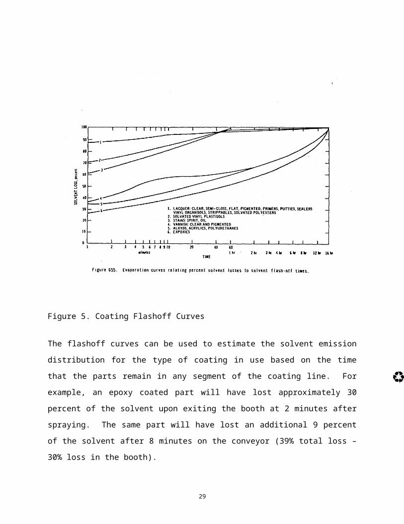
Generic flashoff curves provide the least accurate estimate of solvent emission distributions and
an example of flashoff curves from Reference 5 is presented in Figure 5.
98

99

Figure 5. Coating Flashoff Curves
The flashoff curves can be used to estimate the solvent emission distribution for the type of
coating in use based on the time that the parts remain in any segment of the coating line. For
example, an epoxy coated part will have lost approximately 30 percent of the solvent upon
100

exiting the booth at 2 minutes after spraying. The same part will have lost an additional 9
percent of the solvent after 8 minutes on the conveyor (39% total loss – 30% loss in the booth).
Increased accuracy in the solvent emission distribution can be achieved through the use of either
laboratory testing or testing on the coating line. For laboratory testing, coated parts are weighed
at specific time intervals that correspond to the change in line segments. The resulting weight
101

change at each time interval corresponds to the solvent loss. Similarly, testing on the actual
coating line involves weighing parts at each process transition and recording the weight change
to determine the solvent loss for the specific segment of the coating line.
If an oven is used in the process, the parts are usually dry upon exiting the oven. In the case of
dry parts, the solvent loss in the oven will equal the remaining amount of solvent in the coating
102

on the part. For example, if 39 percent of the solvent is lost in the booth and on the conveyor, 61
percent of the solvent is lost in the oven (100% - 39% lost in the booth and conveyor).
CLASSIFICATION OF CALCULATIONS AND SUMMARY OF REQUIRED DATA
AND DATA SOURCES
103

Emission calculations for surface coating fall into two broad categories as follows:
Concentration units; and
Mass units.
Concentration units, such as lb VOC/gallon, most frequently appear in rules (RACT, NSPS,
NESHAP etc.), new source review (NSR) permits, and Title V permits and are designed to 104

reduce emissions from existing sources and limit emissions from new sources. These standards
are written for specific operations in specific industries to achieve emission reductions over
current practices.
Mass units, such as lb/hr or tons/yr, are needed to complete TCEQ NSR permit applications,
emission inventories, and emission fee calculations, and are used as inputs into atmospheric
105

dispersion models. The dispersion models are used to demonstrate compliance with the National
Ambient Air Quality Standards (NAAQS) and TCEQ state property line standards for particulate
matter and H2S, as well as providing the off-property concentrations of all species to be emitted
by the facility to demonstrate that the facility emissions will not be detrimental to public health.
106

The data required to complete the calculation depends on the units that the standard or limit
contains. The most common units and the required data appear in Tables 6 through 10.
TABLE 6SURFACE COATING CALCULATIONS - SOLVENT EMISSIONS DATA REQUIREMENTS AND DATA SOURCES
Concentration Limits
107

lb VOC/gal of coating lb VOC/gal solids lb VOC/gal solids applied Coating Data Required Units Data Source Units Data Source Units Data Source
Coating Consumptionlb/gal MSDS lb/gal MSDS lb/gal MSDS
Multiple Component Mixing
Ratiolb/gal MSDS lb/gal MSDS lb/gal MSDS
Thinning Ratiolb/gal MSDS lb/gal MSDS lb/gal MSDS
Coating Density lb/gal MSDS lb/gal MSDS lb/gal MSDS
108

Coating/Component VOC
Contentlb/gal MSDS lb/gal MSDS lb/gal MSDS
Coating Water Content lb/gal MSDS lb/gal MSDS lb/gal MSDS
Coating Exempt Solvent
Content lb/gal MSDS lb/gal MSDS lb/gal MSDS
Coating Volume VOC
Content Percent MSDS/Technical Data Percent MSDS/Technical Data Percent MSDS/Technical Data
Sheet/Vendor Sheet/Vendor Sheet/VendorThinner Density lb/gal MSDS lb/gal MSDS lb/gal MSDS
109

VOC Control EfficiencyPercent
Control Equipment Vendor Percent
Control Equipment Vendor Percent
Control Equipment Vendor
Coating Volume Solids
Content Percent MSDS/Technical Data Percent MSDS/Technical Data Percent MSDS/Technical Data
Sheet/Vendor Sheet/Vendor Sheet/Vendor
Transfer EfficiencyNA NA Percent
Tables/Calculation/ Testing
110

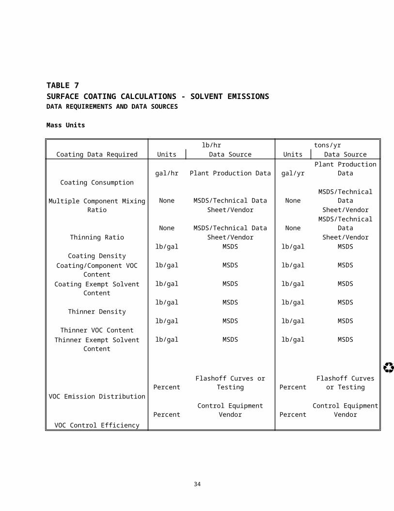
TABLE 7SURFACE COATING CALCULATIONS - SOLVENT EMISSIONS DATA REQUIREMENTS AND DATA SOURCES
Mass Units
lb/hr tons/yrCoating Data Required Units Data Source Units Data Source
111

Coating Consumptiongal/hr Plant Production Data gal/yr Plant Production Data
Multiple Component Mixing RatioNone MSDS/Technical Data None MSDS/Technical Data
Sheet/Vendor Sheet/Vendor
Thinning RatioNone MSDS/Technical Data None MSDS/Technical Data
Sheet/Vendor Sheet/Vendor
Coating Densitylb/gal MSDS lb/gal MSDS
Coating/Component VOC Contentlb/gal MSDS lb/gal MSDS
112

Coating Exempt Solvent Content lb/gal MSDS lb/gal MSDS
Thinner Densitylb/gal MSDS lb/gal MSDS
Thinner VOC Contentlb/gal MSDS lb/gal MSDS
Thinner Exempt Solvent Contentlb/gal MSDS lb/gal MSDS
VOC Emission Distribution Percent Flashoff Curves or Testing Percent Flashoff Curves or
Testing113

VOC Control EfficiencyPercent Control Equipment Vendor Percent
Control Equipment Vendor
114

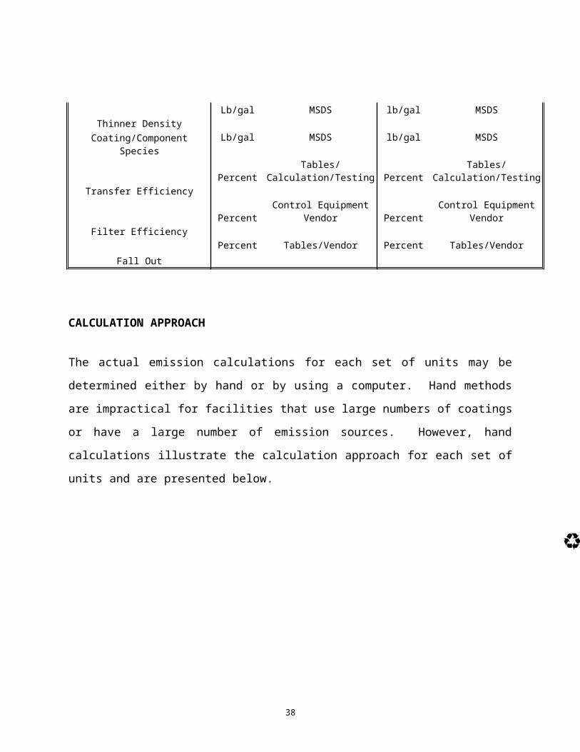
TABLE 8SURFACE COATING CALCULATIONS - SOLIDS EMISSIONS DATA REQUIREMENTS AND DATA SOURCES
115

Mass Units
lb/hr tons/yrCoating Data Required Units Data Source Units Data Source
Coating Consumptiongal/hr Plant Production Data gal/yr Plant production data
Multiple Component Mixing RatioNone MSDS/Technical Data None MSDS/Technical Data
Sheet/Vendor Sheet/VendorThinning Ratio None MSDS/Technical Data None MSDS/Technical Data
116

Sheet/Vendor Sheet/Vendor
Coating Densitylb/gal MSDS lb/gal MSDS
Thinner Densitylb/gal MSDS lb/gal MSDS
Coating/Component Solids Content lb/gal MSDS lb/gal MSDS
Transfer EfficiencyPercent Tables/Calculation/Testing Percent Tables/Calculation/Testing
Filter Efficiency Percent Control Equipment Vendor Percent Control Equipment Vendor
117

Fall OutPercent Tables/Vendor Percent Tables/Vendor
118

119

TABLE 9SURFACE COATING CALCULATIONS - SOLVENT SPECIES EMISSION RATES DATA REQUIREMENTS AND DATA SOURCES
Species Mass Emission Rates
lb/hr tons/yr
120

Coating Data Required Units Data Source Units Data Source
Coating Consumptiongal/hr Plant Production Data gal/yr Plant production data
Multiple Component Mixing RatioNone MSDS/Technical Data None MSDS/Technical Data
Sheet/Vendor Sheet/Vendor
Thinning RatioNone MSDS/Technical Data None MSDS/Technical Data
Sheet/Vendor Sheet/Vendor
Coating Densitylb/gal MSDS lb/gal MSDS
Coating/Component Species Percent MSDS Percent MSDS
121

Thinner Densitylb/gal MSDS lb/gal MSDS
Thinner SpeciesPercent MSDS Percent MSDS
VOC Emission DistributionPercent Flashoff Curves or Testing Percent Flashoff Curves or Testing
VOC Control EfficiencyPercent Control Equipment Vendor Percent Control Equipment Vendor
122

123

TABLE 10
124

SURFACE COATING CALCULATIONS - SOLIDS SPECIES EMISSION RATES DATA REQUIREMENTS AND DATA SOURCES
Species Mass Emission Rates
lb/hr tons/yrCoating Data Required Units Data Source Units Data Source
Coating Consumptiongal/hr Plant Production Data gal/yr Plant production data
125

Multiple Component Mixing RatioNone MSDS/Technical Data None MSDS/Technical Data
Sheet/Vendor Sheet/Vendor
Thinning RatioNone MSDS/Technical Data None MSDS/Technical Data
Sheet/Vendor Sheet/Vendor
Coating DensityLb/gal MSDS lb/gal MSDS
Thinner DensityLb/gal MSDS lb/gal MSDS
Coating/Component Species Lb/gal MSDS lb/gal MSDS
126

Transfer EfficiencyPercent Tables/Calculation/Testing Percent Tables/Calculation/Testing
Filter EfficiencyPercent Control Equipment Vendor Percent Control Equipment Vendor
Fall OutPercent Tables/Vendor Percent Tables/Vendor
127

CALCULATION APPROACH
The actual emission calculations for each set of units may be determined either by hand or by
using a computer. Hand methods are impractical for facilities that use large numbers of coatings
or have a large number of emission sources. However, hand calculations illustrate the
calculation approach for each set of units and are presented below.
128

Coating As-Applied VOC Content
Single Component Coating
Data Requirements
129

Coating VOC content from MSDS or technical data sheet
Since the coating is not mixed with any thinners or any other components the as-applied VOC
content will be as stated.
Single Component Coating with Thinner
130

Data Requirements
Coating VOC Content 2.8 lb VOC/gal
Thinner VOC Content 7.3 lb VOC/gal
Thinning Ratio 10 : 1
10 Parts Coating 5 gal
131

1 Part thinner 0.5 gal
11 Parts Mixed Coating 5.5 gal
Calculate VOC Content
2.8 lb VOC 5 gal +
7.3 lb VOC 0.5 gal
=17.65 lb VOC
132

Gal gal
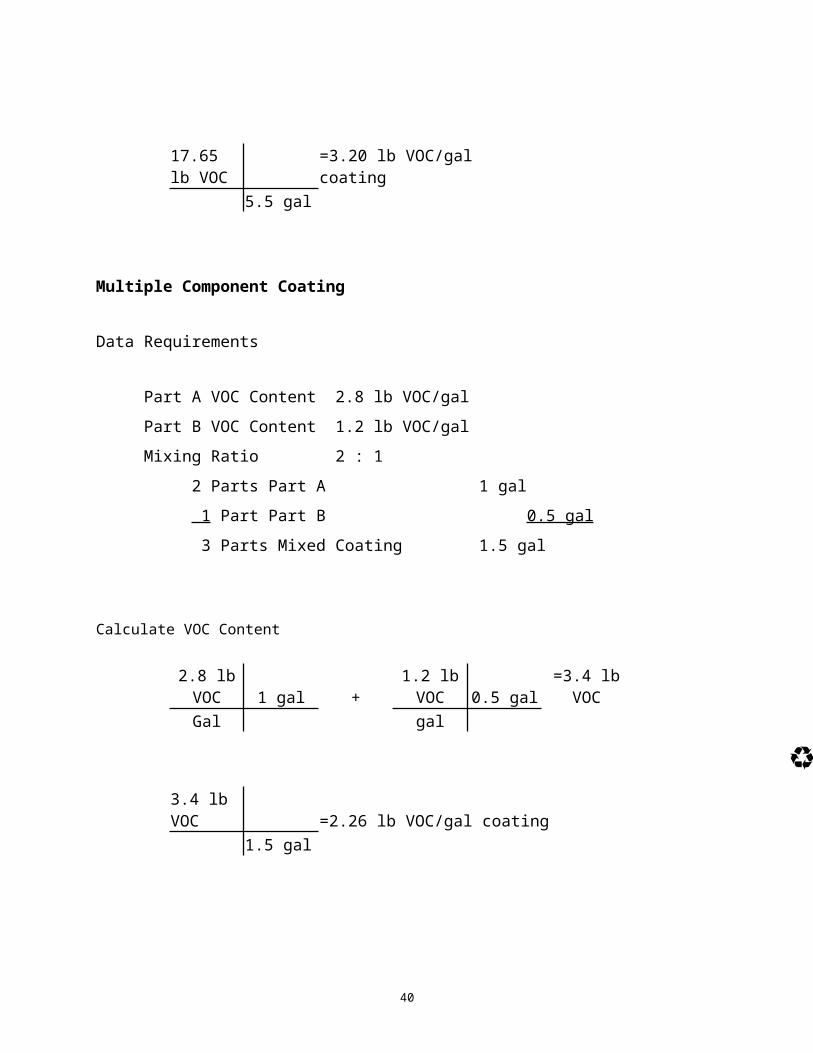
17.65 lb VOC =3.20 lb VOC/gal coating 5.5 gal
133

Multiple Component Coating
Data Requirements
Part A VOC Content 2.8 lb VOC/gal
Part B VOC Content 1.2 lb VOC/gal
Mixing Ratio 2 : 1134

2 Parts Part A 1 gal
1 Part Part B 0.5 gal
3 Parts Mixed Coating 1.5 gal
Calculate VOC Content
135

2.8 lb VOC 1 gal +
1.2 lb VOC 0.5 gal =3.4 lb VOC
Gal gal
3.4 lb VOC =2.26 lb VOC/gal coating 1.5 gal
136

137

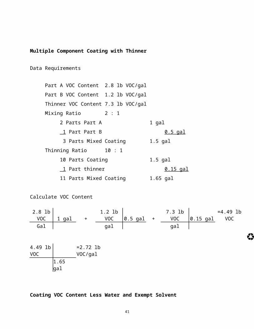
Multiple Component Coating with Thinner
Data Requirements
Part A VOC Content 2.8 lb VOC/gal
Part B VOC Content 1.2 lb VOC/gal
138

Thinner VOC Content7.3 lb VOC/gal
Mixing Ratio 2 : 1
2 Parts Part A 1 gal
1 Part Part B 0.5 gal
3 Parts Mixed Coating 1.5 gal
Thinning Ratio 10 : 1
139

10 Parts Coating 1.5 gal
1 Part thinner 0.15 gal
11 Parts Mixed Coating 1.65 gal
Calculate VOC Content
2.8 lb 1 gal + 1.2 lb VOC 0.5 gal + 7.3 lb VOC 0.15 gal =4.49 lb 140

VOC VOCGal gal gal
4.49 lb VOC =2.72 lb VOC/gal 1.65 gal
141

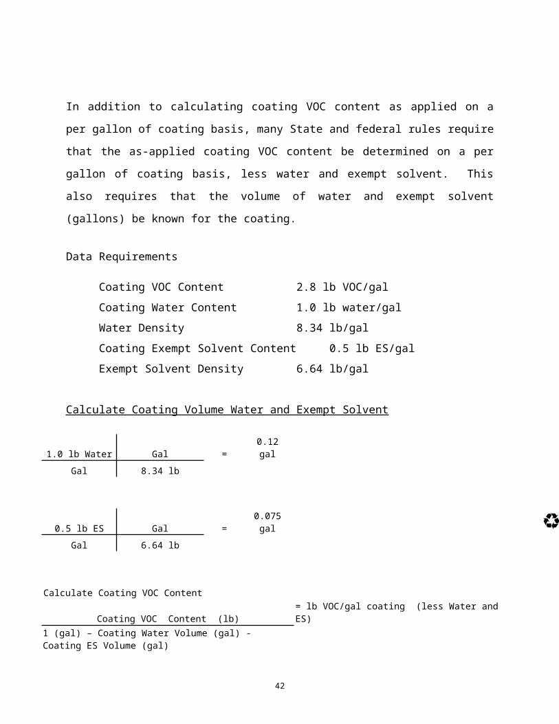
Coating VOC Content Less Water and Exempt Solvent
In addition to calculating coating VOC content as applied on a per gallon of coating basis, many
State and federal rules require that the as-applied coating VOC content be determined on a per
gallon of coating basis, less water and exempt solvent. This also requires that the volume of
water and exempt solvent (gallons) be known for the coating.
142

Data Requirements
Coating VOC Content 2.8 lb VOC/gal
Coating Water Content 1.0 lb water/gal
Water Density 8.34 lb/gal
Coating Exempt Solvent Content 0.5 lb ES/gal
Exempt Solvent Density 6.64 lb/gal143

144

Calculate Coating Volume Water and Exempt Solvent
1.0 lb Water Gal = 0.12 galGal 8.34 lb
0.5 lb ES Gal = 0.075 galGal 6.64 lb
145

Calculate Coating VOC Content
Coating VOC Content (lb) = lb VOC/gal coating (less Water and ES)1 (gal) – Coating Water Volume (gal) - Coating ES Volume (gal)
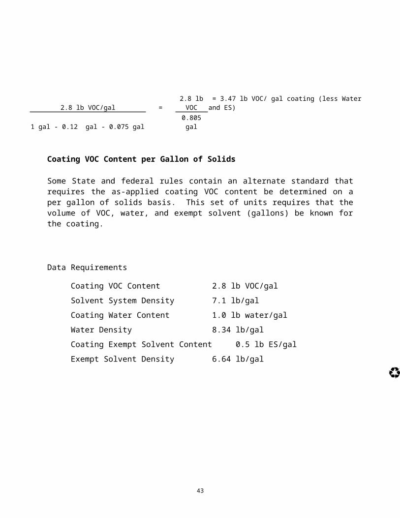
2.8 lb VOC/gal = 2.8 lb VOC = 3.47 lb VOC/ gal coating (less Water and ES)146

1 gal - 0.12 gal - 0.075 gal 0.805 gal
Coating VOC Content per Gallon of Solids
Some State and federal rules contain an alternate standard that requires the as-applied coating VOC content be determined on a per gallon of solids basis. This set of units requires that the volume of VOC, water, and exempt solvent (gallons) be known for the coating.
147

Data Requirements
Coating VOC Content 2.8 lb VOC/gal
Solvent System Density 7.1 lb/gal
Coating Water Content 1.0 lb water/gal
148

Water Density 8.34 lb/gal
Coating Exempt Solvent Content 0.5 lb ES/gal
Exempt Solvent Density 6.64 lb/gal
149

Calculate Coating Volume VOC, Water and Exempt Solvent
2.8 lb VOC gal = 0.394 galGal 7.1 lb
1.0 lb Water gal = 0.12 galGal 8.34 lb
150

0.5 lb ES gal = 0.075 galGal 6.64 lb
Calculate Coating VOC Content
Coating VOC Content (lb) = lb VOC/gal solids1 (gal) - Coating VOC Volume (gal) - Coating Water Volume (gal) - Coating ES Volume (gal)
151

2.8 lb VOC/gal = 2.8 lb VOC = 6.81 lb VOC/ gal solids1 gal - 0.394 gal - 0.12 gal - 0.075 gal 0.411 gal
Coating VOC Content per Gallon of Solids Applied
152

The final set of VOC concentration units are commonly seen in NSPS standards and have units
of lb VOC/gal solids applied. This type of standard allows for greater compliance flexibility due
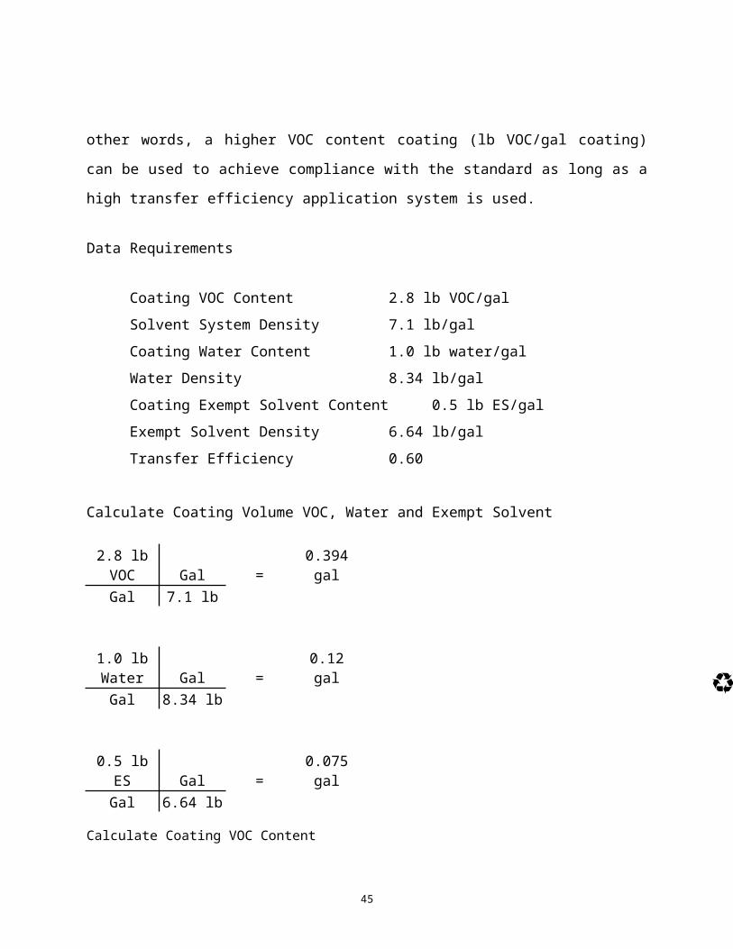
to allowing transfer efficiency to be taken into consideration. In other words, a higher VOC
content coating (lb VOC/gal coating) can be used to achieve compliance with the standard as
long as a high transfer efficiency application system is used.
153

Data Requirements
Coating VOC Content 2.8 lb VOC/gal
Solvent System Density 7.1 lb/gal
Coating Water Content 1.0 lb water/gal
Water Density 8.34 lb/gal
154

Coating Exempt Solvent Content 0.5 lb ES/gal
Exempt Solvent Density 6.64 lb/gal
Transfer Efficiency 0.60
Calculate Coating Volume VOC, Water and Exempt Solvent
2.8 lb VOC Gal = 0.394 gal155

Gal 7.1 lb
1.0 lb Water Gal = 0.12 galGal 8.34 lb
0.5 lb ES Gal = 0.075 gal
156

Gal 6.64 lb
Calculate Coating VOC Content
Coating VOC Content (lb) = lb VOC/gal solids applied1 (gal) - Coating VOC Volume (gal) - Coating Water Volume (gal) - Coating ES Volume (gal) TE
157

2.8 lb VOC/gal = 2.8 lb VOC = 11.35 lb VOC/ gal solids applied1 gal – 0.394 gal - 0.12 gal - 0.075 gal 0.6 0.411 gal 0.6
Coating Mass Emission Rates
Emission Rates – Parts Dry in the Spray Booth158

Data Requirements
Coating VOC Content 3.5 lb VOC/gal
Coating PM Content 8.0 lb PM/gal
Daily Coating Consumption 6.0 gal
Spray Time 3.0 hr
Annual Coating Consumption 4750 gal/yr159

Transfer Efficiency 0.60
Filter Efficiency 0.97
Fall Out Factor 0.95
160

Calculate Short Term VOC Emission Rate
3.5 lb VOC 6.0 gal = 7.0 lb VOC/hrgal 3 hr
161

Calculate Short Term PM Emission Rate
8.0 lb PM 6.0 gal 1 - 0.6 1 - 0.97 1 - 0.95 = 0.0096 lb PM/hrGal 3 hr
162

Calculate Annual VOC Emission Rate
3.5 lb VOC 4750 gal 1 ton = 8.31 ton VOC/yrgal Yr 2000 lb
163

Calculate Annual PM Emission Rate
8.0 lb PM 4750 gal 1 - 0.6 1 - 0.97 1 - 0.95 1 ton = 0.011 ton PM/yrGal Yr 2000 lb
Emission Rates – Parts Dry on the Conveyor and Oven
164

Coating VOC Content 3.5 lb VOC/gal
Daily Coating Consumption 6.0 gal
Spray Time 3.0 hr
Annual Coating Consumption 4750 gal/yr
Transfer Efficiency 0.60
Solvent Loss in Booth 0.30
165

Solvent Loss on Conveyor 0.09
Solvent Loss in the Oven 0.61
166

Calculate Total Short Term VOC Emissions for the Coating Line
3.5 lb VOC 6.0 gal = 7.0 lb VOC/hrGal 3 hr
167

168

Calculate Short Term VOC Emission Rate for Each Coating Line Segment
Spray Booth
Part Overspray
TEBooth
Flashoff 1-TE
169

7.0 lb VOC 0.60 0.30 + 7.0 lb VOC 1 - 0.6 = 4.06 lb VOC/hrhr hr
Conveyor
170

TE Conveyor Flashoff
7.0 lb VOC 0.60 0.09 = 0.37 lb VOC/hrhr
Drying Oven
171

TEOven
Flashoff
7.0 lb VOC 0.60 0.61 = 2.56 lb VOC/hrhr
172

Calculate Total Annual VOC Emissions for the Coating Line
3.5 lb VOC 4750 gal 1 ton = 8.31 ton VOC/yrGal Yr 2000 lb
173

Calculate Annual VOC Emission Rate for Each Coating Line Segment
Spray Booth
Part OversprayTE Booth Flashoff 1-TE
174

8.31 ton VOC 0.60 0.30 + 8.31 ton VOC 1 – 0.6 = 4.81 ton VOC/yryr yr
Conveyor
TE Conveyor Flashoff
175

8.31 ton VOC 0.60 0.09 = 0.45 ton VOC/yryr
Drying Oven
176

TEOven
Flashoff
8.31 ton VOC 0.60 0.61 = 3.04 ton VOC/yryr
177

Only VOC emission rates are calculated in this example since it is assumed that all of the PM
emissions occur within the booth and the emission calculation will be the same as in the previous
example. Most spray booths that have a face velocity of 100 – 200 ft/min will achieve 100
percent capture of both PM and VOC emissions. Actual painting is not the only source of
emissions in these examples. Cleanup solvent can make a significant contribution to the total
annual solvent emissions for the facility. Because cleanup and coating application cannot occur
178

simultaneously, hourly cleanup emission rates should be calculated separately. The short-term
permit limit will be the higher of the two emission rates. Cleanup emission rates should be
determined using the same methodology as used in the VOC emission rate calculations noted
above with consideration given to the amount of spent wash solvent recovered during cleanup.
179

Coating Species Mass Emission Rates
Data Requirements
Coating Density 11.5 lb/gal
Daily Coating Consumption 6.0 gal
Spray Time 3.0 hr180

Annual Coating Consumption 4750 gal/yr
Transfer Efficiency 0.60
Filter Efficiency 0.97
Fall Out Factor 0.95
181

Mixed Coating Formulation
Coating Weight Constituent HAPConstituent CAS No. Fraction Type (P/V/ES) (Y/N)
Methyl Ethyl Ketone 78-93-3 0.20 V YAcetone 67-64-1 0.05 ES NMethanol 67-56-1 0.10 V YVM&P Naphtha 8032-32-4 0.05 V N
182

Strontium Chromate 6/2/89 0.10 P YTitanium Dioxide 13463-67-7 0.15 P YIron Oxide 1332-37-2 0.05 P NEpoxy Resin NA 0.30 P N
183

Calculate Short Term Species Emission Rates
Volatile Species
11.5 lb 6.0 gal Wt. Fraction = 23.0 Weight Fraction lb/hrGal 3 hr
184

Coating Weight Weight Emission Constituent Fraction Fraction lb/hr Rate (lb/hr)
Methyl Ethyl Ketone 0.20 23.0 4.60Acetone 0.05 23.0 1.15Methanol 0.10 23.0 2.30VM&P Naphtha 0.05 23.0 1.15
185

Particulate Species1 - TE 1 - FE 1 - FO
11.5 lb 6.0 gal Wt.
Fraction 1 - 0.60 1 - 0.97 1 - 0.95 = 0.014 Weight Fraction lb/hrgal 3 hr
186

Coating Weight Weight Emission Constituent Fraction Fraction lb/hr Rate (lb/hr)
Strontium Chromate 0.10 0.014 0.0014Titanium Dioxide 0.15 0.014 0.0021Iron Oxide 0.05 0.014 0.0007Epoxy Resin 0.30 0.014 0.0042
187

Calculate Annual Species Emission Rates
Volatile Species
11.5 lb 4750 gal 1 Ton Wt. Fraction = 27.3 Weight Fraction ton/yrgal Yr 2000 lb
188

Coating Weight Weight Emission Constituent Fraction Fraction ton/yr Rate (ton/yr)
Methyl Ethyl Ketone 0.20 27.3 5.46Acetone 0.05 27.3 1.36Methanol 0.10 27.3 2.73VM&P Naphtha 0.05 27.3 1.36
189

Particulate Species
1 - TE 1 - FE 1 - FO
11.5 lb 4750 gal 1 TonWt.
Fraction 1 - 0.60 1 - 0.97 1 - 0.95 = 0.016 Weight Fraction ton/yrgal Yr 2000 lb
190

Coating Weight Weight Emission Constituent Fraction Fraction ton/yr Rate (ton/yr)
Strontium Chromate 0.10 0.016 0.0016Titanium Dioxide 0.15 0.016 0.0024Iron Oxide 0.05 0.016 0.0008Epoxy Resin 0.30 0.016 0.0048
191

The emission distribution for the individual volatile species can be determined using the solvent
loss fractions (flashoff fractions) used in the previous example.
Calculation of HAPS
192

Since the adoption of the Federal Clean Air Act Amendments of 1990, an additional set of
calculations may be necessary to determine the emission rate of hazardous air pollutants (HAPs).
A number of the National Emission Standards for Hazardous Air Pollutants (NESHAPs) under
40 CFR 63 apply to surface coating operations and contain concentration limits (lb HAP/gal) that
affected facilities are required to certify compliance. In addition, the applicability of these rules
and the applicability of Title V operating permits under 40 CFR 70 may also be triggered solely
193

by HAP emissions if they exceed 10 tpy for any individual HAP and 25 tpy in the aggregate for a
site.
Fortunately, HAP emissions can be calculated using the same methods as VOC and speciated
emissions. The only changes to the methods is simply the substitution of coating HAP content
for VOC content to determine compliance with concentration limits. To determine if the 10/25
194

tpy thresholds are exceeded, the speciated emission calculations need only be completed for the
HAP species (see definitions) and compared to the 10 tpy threshold for any individual HAP
species and summed to determine if the total exceeds 25 tpy.
195

Addition of Emission Controls for Solvents
All of the coating scenarios evaluated above do not consider the use of solvent emission controls.
Controls are generally required for three reasons as follows:
The emission standard in federal, state or local rules cannot be met;
196

To meet the requirements of Best Available Control Technology (BACT) in federal,
and TCEQ permits; and
To provide acceptable off property concentrations of the various solvent species to
insure that there will be no adverse effects on public health.
197

Emission controls for surface coating can either be process controls or add-on controls. Process
controls involve changing the basic process to provide greater efficiency in the application of
coatings and in the use of solvents. Process controls typically consist of increasing transfer
efficiency (less coating is used per part) and through the use of high solids coatings (less coating
and solvent used per part). Add-on controls provide significant emission reductions as long as
the unit is used to control the correct portion of the coating line (usually the spray booths and
198

flashoff tunnel) and the emission capture efficiency is high. The most common types of
emission controls are thermal oxidizers in one of many configurations or carbon adsorption
systems. Carbon adsorption systems can work nearly as well as thermal systems provided the
emission species are well known and do not change over time.
199

The emission reductions for process controls can be determined through substituting the revised
transfer efficiencies and coating solvent contents into the emission calculation methods covered
previously. For add-on controls, the emission calculation methods need to be modified through
the use of an additional term that includes the control efficiency (CE) of the add-on control
equipment as follows:
Addition of Emission Controls200

Emission Rate 1 - CE =
Emission Rate 1 - 0.98 = Emission Rate X 0.02
201

This calculation approach works for either concentration units or mass units without
modification.
202

AUTOMATION OF EMISSION CALCULATIONS
203

The emission calculation methods previously described present an orderly approach for hand
calculations but are still far too cumbersome to be used on a daily basis for compliance
demonstrations or for use in permit applications. Fortunately, spreadsheets and databases can be
used to simplify the process and reduce the amount of repetitive data entry through the use of
tables that store specific types of information as follows:
204

Coating and solvent properties such as density, VOC content, mix ratios, species, and
type, etc.;
Configuration of the facility such as number of booths, filter efficiencies, and VOC
control efficiencies;
205

Dynamic data that includes transfer efficiency and changes in flashoff due to changes
in coatings and conveyor speed; and
Daily data that includes the amount of each coating and solvent mixed, applied in
each booth or coating line, and transferred to waste.
206

This type of approach allows the data to be easily updated, sorted by type of product (polyester,
epoxy etc.), type of air contaminant (P, V, ES, HAP), date, or booth. As can be seen from the
emission calculation examples, a great deal of data is common between the various emission
standard and the software can draw from common tables to produce a variety of preformatted
reports to demonstrate regulatory compliance or regulatory applicability. In addition, emission
calculation automation can also provide management with useful information on production
207

costs such as the cost of coating per part, comparison of the amount of coating used by different
crews on the same parts, and provide opportunities for process improvement and reductions in
operating costs.
CONCLUSIONS
208

Emission calculations for surface coating facilities have become more important than ever for
facilities to demonstrate compliance with regulatory and permit limits as well as initially setting
permit emission limits. This task can be simplified if accurate coating and facility data is
collected through a partnership with coating and equipment vendors, facility production
operations, and facility management. Understanding how to collect this data and calculate both
concentration and mass emission rates will allow the environmental staff to more easily prepare
209

permit applications, and upon issuance of the permit more easily demonstrate compliance with
permit and other regulatory emission limits.
210

REFERENCES
1. Clean Air Act, §112[42 USC 7142] National Emission Standard for Hazardous Air
Pollutants, §112(b) List of Pollutants
211

2. Texas Commission on Environmental Quality – 2005 Emission Inventory Guidelines –
2005. Document No. RG-360_05, December 2005 (available online at:
http://www.tceq.state.tx.us/comm_exec/forms_pubs/pubs/rg/rg-360_05/rg-
360_05_1390103.pdf ).
212

3. Texas Commission on Environmental Quality – General Air Quality Rules, 30 TAC
§101.1, June 15, 2005 (available online at:
http://www.tceq.state.tx.us/assets/public/legal/rules/rules/pdflib/101a.pdf ).
4. Texas Commission on Environmental Quality – Control of Air Pollution from Volatile
Organic Compounds, 30 TAC §115.10 and 30 TAC §115.420, May 5, 2005 (available
213

online at: http://www.tceq.state.tx.us/assets/public/legal/rules/rules/pdflib/115a.pdf and
http://www.tceq.state.tx.us/assets/public/legal/rules/rules/pdflib/115e.pdf ).
5. Air Pollution Engineering Manual, AP-40. 2nd ed., J. .A. Danielson, Ed.; Air Pollution
Control District of Los Angeles, Environmental Protection Agency, Office of Air and
Water Programs, Office of Air Quality Planning and Standards, Research Triangle Park,
NC, May 1973 214

6. Air Pollution Engineering Manual. Anthony J. Buonicore and Wayne T. Davis, Ed., Air
and Waste Management Association, 1992, p. 362
7. Texas Natural Resource Conservation Commission – Air Permit Technical Guidance for
Coating Sources: Surface Coating Operations, April 2001
215

8. Calculations on particle size paints prepared by D.T. Emery of Phillips Petroleum
Company in Bartlesville, Oklahoma, January 1993;
9. Droplet distribution information prepared by Dan Carroll of Coltec Industries in Des
Moines, Iowa, November 1992;
216

10. Determination of Particle Size Distributions for Airless Spray prepared by K.C. Kwok,
Ph.D. for Rescar Inc. of Downers Grove, Illinois, January 1994;
11. IWATA Test Report supplied by Glen Nelson, Project Manager for Binks Manufacturing
Company of Franklin Park, Illinois, July 1993; and
217

12. CORROSION 95 - Paper No. 634, Cost Effective Solutions Today and Beyond 2000 with
Supercritical Fluid Technology prepared by R.J. Woods and D.C. Busby, Union Carbide
Corporation, South Charleston, WV.
218